1
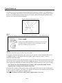
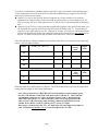
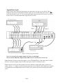
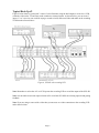
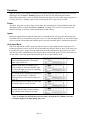
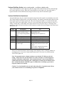
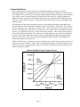
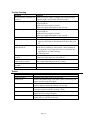
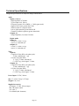
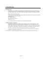
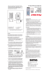
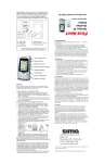
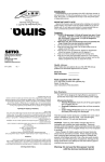
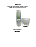
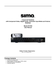
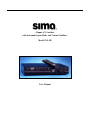
4 Input A/V Switcher with Automatic Input Mode and Volume Stabilizer Model SVS-4D User Manual Table of Contents WHAT’S INCLUDED......................................................................... 2 INTRODUCTION ............................................................................... 3 IMPORTANT SAFETY PRECAUTIONS........................................ 3 FRONT PANEL................................................................................... 4 REAR PANEL ..................................................................................... 5 IR REMOTE CONTROL, SRC-1...................................................... 5 TYPICAL HOOK UP ......................................................................... 6 OPERATION ..................................................................................... 10 POWER ............................................................................................. 10 INPUTS.............................................................................................. 10 AUTO INPUT MODE .......................................................................... 10 VOLUME STABILIZER ACTIVE ........................................................... 11 VOLUME STABILIZATION ADJUSTMENT ............................................ 11 HOW IT WORKS ............................................................................. 12 SIMPLIFIED BLOCK DIAGRAM OF THE SVS-4D ................................. 12 AUTOMATIC INPUT SENSING............................................................. 12 VOLUME STABILIZATION .................................................................. 13 VOLUME STABILIZER INPUT / OUTPUT CURVES................................ 13 COMPOSITE TO S-VIDEO CONVERSION ............................................. 14 TROUBLE SHOOTING ................................................................... 15 TERMS............................................................................................... 15 TECHNICAL SPECIFICATIONS .................................................. 16 LIMITED WARRANTY................................................................... 17 What’s Included 1 - SVS-4D A/V switcher unit 1 - AC power adapter, 15 vdc. 1 - Triple A/V RCA cable, 1 meter long 1 - SRC-1 IR remote control, with batteries 1 - This instruction manual 2002 by Sima Products Corp. All rights reserved. No part of this publication may be reproduced or transmitted in any form or by any means without prior written permission from Sima Products Corp. Page 2 Introduction The Sima model SVS-4D, 4 Input Audio / Video Switcher with Automatic Input Mode (AIM) and Volume Stabilization has been designed for use with home theater, DSS satellite, DVD, audio recording equipment as well as for background music applications. The SVS-4D has the following features: • Four A/V inputs to allow you to add more A/V sources such as DVD, satellite dish, VCR, games, etc. to your TV and home theater system. The unit supports both stereo and digital audio, as well as composite and S-Video. • Dual A/V outputs to connect to your TV, your surround sound receiver and/or a recording VCR. • Composite video to S-Video conversion to simplify hook-up in systems using both composite and S-Video. • Digital Audio Conversion simplifies your hookup by providing outputs for both coaxial and optical audio signals regardless of the source. • Automatic Input Mode (AIM) provides automatic switching to active input without manual selection. Simply turn on your VCR and the SVS-4D connects it automatically to the TV. • Volume Stabilization circuitry to maintain constant audio volume levels for late night viewing or when channel surfing. It can also be adjusted to add impact to old movies by increasing the dynamic range. • IR remote control to select a different input or mode. • Brightness control for the front panel display allows you to dim the lights for nighttime use (via the remote only). Warnings Important Safety Precautions When using this product, basic safety precautions should always be followed to reduce the risk of fire and electric shock, including the following: Read and understand all instructions. Follow all warnings and instructions marked on this product. Unplug this product from wall outlets before cleaning. Do not use liquid or aerosol cleaners. Use a damp cloth for cleaning. To prevent fire or shock hazard, do not expose this product to rain or moisture. Do not use near a bathtub, wash bowl, sink, or laundry tub; do not use in a wet basement or in a swimming pool. To avoid electrical shock, do not open the case of this product. Operate this product using only the power supply included with it or provided as an accessory. If you are not sure of the type of power supplied to your home, consult your dealer or local power company. Do not overload electrical outlets or extension cords as this can result in fire or electric shock. The unit should be situated away from heat sources such as radiators, stoves, etc. The unit should be situated so that its location or position does not interfere with its proper ventilation. Page 3 Front Panel Figure 1, SVS-4D front panel Controls 1 - Power / Stand-by - Press to turn unit on or off. The Power/Stand by light above the switch will be on when the unit is operational and dim when it is in the standby mode. 2 - Inputs 1 through 4 - Press to select the desired input. The light above the switch will light to indicate the current active input. 3 - Auto Input Mode - Press to turn AIM on or off. If on, the unit will scan the video inputs and automatically turn on and select the input to the device you turned on. 4 - Volume Stabilization Adjustment - This controls the amount of dynamic range you want. In the middle, at the 1:1 setting, the input is equal to the output, so there is no affect on the audio signal. If the knob is rotated counter-clockwise towards the 10:1 Page 4 setting, the audio will remain more constant. This will bring up soft dialogue and reduce loud sounds. If the knob is rotated clockwise towards the 1:2 setting, the unit will increase the dynamic range and make loud sounds louder and soft sounds quieter to add impact to music or movies. 5 - Volume Stabilizer Active - Press to turn Volume Stabilization on or off. If active, the light will be on and the audio will go though the Volume Stabilization circuitry to either increase or decrease (depending on the setting of the Volume Stabilization adjustment) the dynamic range of the audio. The light will be off when the Volume Stabilization is bypassed. Rear Panel Figure 2, SVS-4D rear panel 6 - S-Video inputs, 1 through 4 from the S-Video output of your VCR, DSS or DVD devices. 7 - Composite Video inputs, 1 through 4 from the composite video output of your VCR, DSS or DVD devices. 8 - Left and Right audio inputs, 1 through 4 from the audio output of your VCR, DSS or DVD devices. 9 - S-Video outputs, A and B that connects to the input on your TV or VCR 10 - Composite Video outputs, A and B that connects to the input on your TV or VCR 11 - Left and Right audio outputs, A and B that connects to the audio inputs on your TV, VCR or surround sound receiver 12 – Coaxial inputs for digital audio connect to the coaxial output of your DVD, CD player etc. 13 – Optical inputs for digital audio connect to the optical output of your DVD, CD player etc. 14 – Coaxial output for digital audio that connects to the coaxial input of stereo receiver. 15 – Optical output for digital audio that connects to the optical input of stereo receiver. 16 - 15V DC input from the AC wall power supply IR Remote Control, SRC-1 Fig. 3, SRC-1 All the buttons on the SRC-1 IR remote control work just like the buttons on the front of the SVS-4D, with the exception of the DISPLAY button. See descriptions above (under the heading “Front Panel”) for more information POWER - Turns SVS-4D on or off. DISPLAY - Pressing this button cycles through three levels of brightness on the front panel lights - bright, dim or off. When the Display is set in the “off” mode, the lights will light for a few seconds when any button is pressed. VS ACTIVE - Toggles between the Volume Stabilizer being active or in the bypass mode. AUTO INPUT - Toggles between the Automatic Input Selection mode being on or off. INPUT 1 through 4 - Selects desired input. Be sure to install the two AAA batteries in the SRC-1 remote before using. Slide the cover open on the SRC-1 remote in the direction of the arrow and install the batteries as shown inside the unit. Page 5 Typical Hook up This shows a overview of a typical system with the SVS-4D using 4 A/V sources, a TV and Surround system. The outputs of up to 4 devices can feed into the inputs on the SVS-4D. It can then select one of the devices to watch on your TV and/or listen on your receiver. Refer to the diagrams on the next few pages for more detailed connection diagrams. Figure 4, Overview of typical system Step 1 Connect the AC adapter to 120 VAC and plug the DC cord into the 15 v input on the SVS-4D. Power supply Use the 15V DC adapter (included) to provide power for the SVS-4D. The adapter connects to the unit as shown in the diagram at left and plugs into a standard 120V AC wall outlet. Step 2 You need to determine how you want to use your system. If you want to watch and listen to the video sources on your TV and / or your surround sound receiver, see figure 5 on page 8. This diagram only shows inputs 1 and 2 being used. Inputs 3 and 4 are connected in the same manner. If you want to be able to watch the video sources on your TV, listen on your surround sound receiver and tape from the sources plugged into the SVS-4D, see figure 6 on page 9. This shows how to connect one of the outputs of the SVS-4D to the Audio and Video inputs on the VCR that you will use for recording. Note: Do not select the same input that the recording VCR is connected to (input 4 in this diagram) while recording or loud feedback could occur. If you only have composite video signals or only S-Video signals, then use the one type in your system. If your TV only has composite video inputs, you must use all composite video signals into the SVS-4D as it will not convert S-Video signals to composite video. Note: the SVS-4D does not convert analog audio to digital audio or visa versa. Page 6 If you have a combination of standard composite video (RCA type jacks) and S-Video (mini-din jacks) on your equipment you can only feed one or the other but not both to any given input to the SVS-4D. In this case you have several options. Option A: For ease of use, the SVS-4D has a composite to S-Video converter. You can feed a combination of composite and S-Video to the SVS-4D and feed only a S-Video signal to your TV. This lets you use just one S-Video input on your TV and all sources will automatically be displayed there. Option B: If your TV has 2 video inputs that supports both composite video and S-Video inputs, you can feed both the composite and S-Video outputs from the SVS-4D to your TV. You will have to select the correct video input on your TV, composite or S-Video. This will give you the best picture quality. Note that this only works if the composite video and S-Video inputs are two separate inputs on your TV. Otherwise the picture may be blank, black and white or have lines and streaks. Fill in the chart below to help you organize and remember what devices are connected to the inputs and outputs. Save for future reference. Composite Standard L&R Inputs From (VCR, DSS, etc.) Digital (analog) audio audio #1 #2 #3 #4 Outputs To (TV, Receiver, etc.) Composite Standard L&R audio (analog) Digital audio A B Remember both the A and B outputs are identical. The SVS-4D has buffers to prevent one output from loading the other output for best system performance. Note: Most systems have a VHF/UHF cable from an antenna or cable company going into the VCR and then a VHF/UHF cable between the VCR and TV. This is OK but you still must connect the A/V cables as shown in figures 5 and 6. Having both the VHF/UHF cable and the A/V cable would allow you to record a program off of the cable on your VCR (cable input) while watching a different program/movie from another device (DVD) via the SVS-4D on your TV via the A/V input. Don’t forget, you must select the TV’s A/V input (also call video input or line input on some TV brands) not channel 3 or 4 to view the output of the SVS-4D. Page 7 Typical Hook Up #1 Figure 5 below shows a hook-up showing only two input sources. Be sure you use either S-Video or composite video inputs, but not both on the same input. The one SVS-4D output goes to the TV so you can watch and listen on your TV. The second output (audio only) goes to the stereo receiver so you can listen to music or surround sound audio using your stereo receiver. Figure 5, Hook-up in typical system Note 1: Use of the S-video output requires TV to have S-video input. Note 2:Connect L&R audio output to hear audio from TV set with stereo receiver off. Note: Remember to always connect the outputs on your VCR/DSS/DVD/etc. to the inputs on the SVS-4D. Likewise, connect the outputs on the SVS-4D to the inputs on the TV/VCR/Receiver/etc.. Note: If you have one or more devices that are not stereo and have a single audio output, you have two options. 1) Use a “Y” adapter (available from any electronics store) to split the mono signal into two signals to feed both the Left and Right inputs on the SVS-4D. 2) Use just the left connector for the audio of that source. Page 8 Typical Hook Up #2 Figure 6 below shows a system with 3 sources. It also illustrates using the dual outputs to record on a VCR, watch the video on the TV and listen to the sound on a surround system. As shown below, you can record inputs 1, 2 or 3 (not 4 as you would be trying to record to itself) and record video and audio on the recording VCR from the selected source. Figure 6, SVS-4D with recording VCR Note: Remember to select the A/V or AUX input on the recording VCR to record the output of the SVS-4D. Note: It is advisable to turn auto input selection off to avoid the SVS-4D from selecting input #4 and getting feedback. Note: If you are using a source with s-video then you must use an s-video connection to the recording VCR and to the television. Page 9 Operation When AC power is first applied, all outputs will be muted and all the lights will come on for 1 second and then go out. The Power / Stand-by light will be lit dim red. The Auto Input and Volume Stabilization modes will be active as default. When the unit detects an active video input (composite or S-Video), the Power / Standby light will turn on full and the active input will be selected. Power As long as AC power is not lost, the previous status (last selected input, Volume Stabilizer mode and AIM status) will be resumed when Power / Stand-by is pushed. If AC power was lost, the unit will default with input #1 selected, Volume Stabilization on and AIM on. Inputs Pushing an input button on either the front panel or on the IR remote, will cause the current input and associated LED to go off and the new input to come on. If the Auto Input Mode is on, the selected input will over ride the current input until another input is selected or another input is automatically detected. Auto Input Mode If the Auto Input Mode (AIM) is active, the unit will select a video signal from the video inputs. If a second input becomes active, the SVS-4D will automatically change to the new input. If you want to go to another A/V source, simply select the input using the front panel button or the remote. If you don’t want the SVS-4D to automatically select an active input, turn the AIM mode off. Please note when you activate AIM, it scans the inputs when the SVS-4D is on or in the stand-by mode. When the unit is in the standby mode, the Power/Standby light will be dim and all other lights will be off When a video device is turned on, like a VCR on Input #1, the Power/Standby light will become bright, the input corresponding to the device will turn on. If a second device is turned on (say the DVD player on input #2) the # 2 light will illuminate and it will be selected and fed to your TV If the second device is turned off, after about 5 seconds, input #1 will be selected. If both devices are turned off, after about 5 seconds, the SVS-4D will turn off and go into standby mode waiting for an input. Note: If an input goes off and back on in less than 5 seconds, the SVS-4D may not sense the input change so no input change may occur. Page 10 Volume Stabilizer Active (only on analog audio – no effect on digital audio) If the Volume Stabilizer Active light is on, then the output of the audio switcher will be routed through the Volume Stabilizer circuitry. When the Volume Stabilizer Active light is off, the audio signal is bypassed and the Volume Stabilization setting will not have any affect on the audio signal. Volume Stabilization Adjustment Volume Stabilization lets you control the dynamic range of the audio signal to accommodate your needs. The Volume Stabilizer light must be on for this to function. The numbers around the knob show the ratio of the input signal to the output signal in db. Thus, the setting in the middle (1:1) means that the input signal is the same as the output signal. Likewise, if you set the knob full counter clockwise to the 10:1 setting, it means that a 10 db change in the input volume level will result in only a 1 db change in the output level. This will tend to keep the volume constant even when the sound changes from soft to loud and back to soft. Setting 10:1 2:1 1.3:1 1:1 1:1.3 1:2 Description Maximum compression maintains constant volume level by compressing dynamic range Modest compression Slight compression Normal volume fluctuations Slight expansion Maximum expansion increases dynamic range Use Watching movies late at night Background music Making tapes for airplane use Making tapes for automotive use Minimal audio compression Just like bypass (VS off) Adds some impact to audio sources Restores dynamics to old recordings Reduces hiss and noise below noise “floor” Can “un-do” compression on tapes made with 2:1 compression Hint: If you want the minimal volume changes when changing sources, changing channels or watching a movie, be sure the Volume Stabilization knob is set to the 10:1 position and the VS ACTIVE light is on. Note: It is normal to notice volume variations even with the SVS-4D set to the 10:1 setting. This is due to the fact the human ear is more sensitive to certain frequencies and these will tend to sound louder. Some commercials on TV have been modified to sound louder than the normal program. Although the SVS-4D will not eliminate all of these volume fluctuations with these types of commercials, it will help a great deal to keep the volume level constant. Caution: Very loud sound levels can result when using the 1:2 expansion mode. Keep your volume levels low to avoid damage to speakers or amplifiers Page 11 How it works This section has more technical information for the person who wants to learn more about the SVS-4D. In the block diagram below you can see how the audio and video inputs are selected and fed to the output buffer amplifiers. (Only the left audio channel is shown) Notice how the Volume Stabilizer Active switch allows you to bypass the Volume Stabilizer circuitry. The diagram also shows how the selected composite video signal is fed to the composite video output buffer amplifiers and into the composite to S-Video converter which then feeds the S-Video output. Simplified Block Diagram of the SVS-4D Automatic Input Sensing When the AIM mode is on, the SVS-4D constantly scans the video inputs, both composite and S-Video, waiting for a video input. When you turn on a device (VCR, DSS, etc.) a microprocessor in the SVS-4D senses the video input, turns on the SVS-4D (when it is in the stand-by mode) and selects the input. If a second inputs occurs, the unit will switch to the new input. If the second input is turned off, in about 5 seconds, the unit will go back to the first input. If that input goes off, the unit will turn itself off going back to the stand-by mode in about 5 seconds and wait for an input to become active. Note: The Automatic Input Sensing only senses the video signals and not the audio signals. Page 12 Volume Stabilization The SVS-4D monitors the active audio source and depending upon the setting of the Volume Stabilization adjustment, constantly changes the volume level smoothly to compensate to input volume level changes. Let’.s say the unit is set to the 10:1 setting. When the input level increases by 10 db, that is it gets louder, in just a few milliseconds, the SVS-4D reduces the volume by 9 db so the output only changes by about 1 db. Likewise, if the audio signal gets softer by 10 db, the SVS-4D adds gain to the signal so it is only reduced by about 1 db. This way, the unit automatically brings up soft dialogue when watching movies. The diagram below shows the relationship between an input audio signal and the output audio signal. Normal output level for most consumer equipment is about -10 dbv (aprox. 250 mv rms). This is why all the curves intersect at the -10 dbv point. Looking at the 1:1 line, you can see if an input signal is at the 20 dbv level (slightly soft volume wise) it will come out also at -20 dbv. There is no change. If the unit is set for 10:1 compression, the same -20 input will come out at about -11 dbv as shown in the diagram below. This signal is boosted about 9 db. Likewise, if the input signal goes up to 0 dbv, the output will be -9 dbv. For an input change from -20 dbv to 0 dbv (a 20 db change) the output only changed 2 db (11dbv to -9 dbv). This results in soft conversations being boosted to a normal level and loud special effects being reduced to a normal level. With the SVS-4D set to 1:2 expansion, if the input makes the same -20 dbv to 0 dbv change as above, the output now goes from -30dbv to +10 dbv. This is a 40 db output change for a 20 db input change. This results in soft sounds, including tape hiss and soft conversations, becoming even softer and loud special effects becoming even louder. Volume Stabilizer Input / Output Curves Page 13 Composite to S-Video Conversion The SVS-4D has special circuitry to convert the composite video inputs to the S-Video outputs. The SVS-4D sends the original composite and the generated s-video signal to both sets of outputs. However, if you feed the selected input with a s-video signal, the SVS-4D only sends the s-video signal to the output. Note: Because the S-Video signal is generated from the composite video signal, the quality of the converted S-Video signal will not be as good as a true S-Video signal. For best picture quality use the original S-Video or composite video signals. Digital Audio Conversion The SVS-4D converts the coaxial and optical digital audio inputs and sends the signal out both the coaxial and optical outputs simultaneously. This lets you connect a single optical cable between the SVS-4D and your receiver and feed the SVS-4D with both coaxial and optical inputs. Note: It does not convert the digital signal to analog L+R signals or visa versa. Note: The volume stabilizer only works on analog L+R signals and does not work on the coaxial and optical signals. Page 14 Trouble Shooting Problem Power/Stand-by light does not come on No video output No audio output No input is selected Picture is black and white AIM does not detect device when turned on Unit goes to standby after 5 seconds Volume seems to vary too much between sources Video stays on when in standby mode IR remote does not work Solution Make sure power adapter is plugged into a working outlet. Stand-by light is dim (normal in stand-by mode) Is power light on? Is input light lit? Make sure correct input is selected. Make sure inputs and outputs are not reversed. Is power light on? Is input light lit? Make sure correct input is selected. Make sure inputs and outputs are not reversed. Push STANDBY button so unit is in the ON mode. Your TV is using both composite and S-Video inputs. Use only one or the other to feed into the SVS-4D or into your TV. Is the video cable connected from the device to the SVS-4D? Is the device producing a video picture. Some products do not generate a video signal (just a blue screen) unless the tape/DVD/etc. is actually playing. Is AIM turned on? Normal if there are no video inputs. Either turn video input on or turn AIM off. Make sure Volume Stabilization is active. Set Volume Stabilization to the 10:1 setting. Normal, however, audio is muted Replace batteries in remote. Terms Term composite video compression db dbv expansion S-Video Definition Standard video signal using RCA style jacks Reduce the dynamic range of an audio signal by decreasing loud signals and increasing soft signals. Short for decibels - Measure of relative sound levels . The smaller change a human ear can hear is about 1 db. Measure of absolute voltages. 0 dbv is equal to .775 v rms. Most consumer equipment operates at about -10 dbv. Increase the dynamic range of an audio signal by increasing loud signals and decreasing soft signals Video signal that separates the color signal from the brightness signal and uses mini DIN connectors. Page 15 Technical Specifications Design and specifications are subject to change without notice Audio Inputs, (4 stereo) Input impedance, 47 Kohms Typical input level, 300 mv Frequency response 20 to 20KHz, +/- 3db (bypass mode) Signal to Noise ratio, greater than 70 db THD less than 0.1% (bypass mode) Left to right separation, greater than 60 db Channel to channel separation, greater than 60 db Outputs, (2) Output Impedance, less than 150 ohms Digital Audio Inputs (4) Coaxial (2), 75ohm, 0.5V p-p Optical (2), TOSLINK style Outputs (2) Coaxial (1), 75ohm, 0.5V p-p Optical (1), TOSLINK style Video Input (4) Composite Video (RCA style phono jack) 75 ohm, unbalanced, 1 v p-p S-Video (4 pin mini DIN) Y: 1 vp-p, 75 ohms, unbalanced C: 0.286 V p-p, burst signal, 75 ohms Outputs, (2) Composite Video (RCA style phono jack) 75 ohm, unbalanced, 1 v p-p S-Video (4 pin mini DIN) Y: 1 vp-p, 75 ohms, unbalanced C: 0.286 V p-p, burst signal, 75 ohms Power Input: 15 VDC, 500 ma Size: 13” wide, 8” deep, 2.25” high Weight: 3 lbs, 10 oz. Supplied accessories AC adapter, 15 VDC, 500 ma output SRC- IR remote control A/V cable, 3’ User Manual (this document) Page 16 Limited Warranty Limited Warranty Sima Products Corp. (“Company”) warrants that is the accompanying product proves to be defective to the original purchaser in material or workmanship within 90 days from the original retail purchase, the Company will, at the Company’s option, either repair or replace same without charge (but no cash refund will be made). What you must do to enforce Warranty You must deliver, mail or ship the product, together with both the original bill of sale and this limited Warranty statement as proof of warranty coverage to: Sima Products Corp. Att: Customer Service 140 Pennsylvania Ave., Bld. #5 Oakmont, PA 15139 It is recommended that you contact Sima to obtain a return authorization number. Limitation of Liability and Remedies Sima shall have no liability for any damages due to lost profits, loss of use or anticipated benefits, or other incidental, consequential, special or punitive damages arising from the use of, or the inability to use, this product, whether arising out of contract, negligence, tort or under any warranty, even if Sima has been advised of the possibility of such damages. Sima’s liability for damages in no event shall exceed the amount paid for this product. Sima neither assumes nor authorizes anyone to assume for it any other liabilities. Some states do not allow the exclusion or limitation of incidental or consequential damages, so the above limitation or exclusion may not apply to you. This warranty gives you specific legal rights, and you may also have other rights which vary from state to state. Page 17 NOTES Page 18 Sima Products Corp. 140 Pennsylvania Ave., Bld. #5 Oakmont, PA 15139 USA 412-828-3700 800-345-7462 412-828-3775 FAX Visit us at www.simacorp.com E-mail us at [email protected] Manual # 21595, rev A Page 19