1
Beckett Burner Set-up
Vitorond 100, VR1-22 to -33 Installation and Service
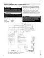
Electrical Connections (with Vitotronic control)
(continued)
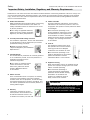
WARNING
Electric shock hazard. Can cause severe personal injury
or loss of life if power source, including service switch
on boiler, is not disconnected before installing or servicing.
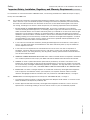
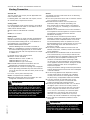
Installations must follow these codes and requirements:
- National Electrical Code, ANSI/NFPA 70, latest edition
and any addtional national, state or local codes.
- In Canada, CSA C22.1 Canadian Electrical Code Part 1
and any local codes.
- Wiring must be N.E.C. Class 1. If original wire as
supplied with boiler must be replaced, type 105°C
wire or equivalent must be used. Supply wiring to boiler
and additional control wiring must be 14 ga. or heavier.
- Provide electrical ground at boiler as required by codes.
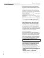
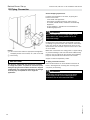
Closed end connectors are factory installed on RED, ORANGE and BLUE
wires. These RED,ORANGE and BLUE wires may or may not be used in
your burner application. See wiring diagram in this manual which is specific
to your burner application. Do not remove or cut any of the closed end
connectors of the RED, ORANGE or BLUE wires, unless it is necessary to do
so. RED wire is live (120VAC) at all times. Do not remove or cut its closed
end connector unless it is necessary to do so. Failure to heed the above
instructions may cause severe personal injury or loss of life.
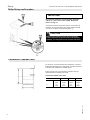
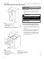
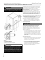
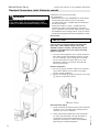
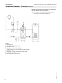
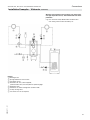
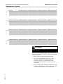
Burner wiring harness (supplied)
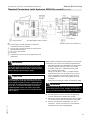
Legend
BL Blue
O Orange
BK Black
W White
G Green
R Red
5583 571 - 01
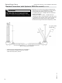
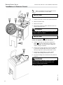
* If Beckett burner is being installed, cut this length
to 6” for connection to burner junction box (located
under the burner primary control).
31