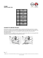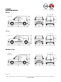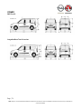
1
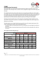
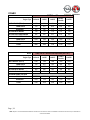
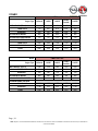
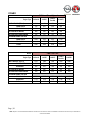
COMBO
CONVERSION GUIDELINES
NEW COMBO
Opel / Vauxhall - Light Commercial Vehicles
EDITION: JUNE 2012
Page | 1
NOTE: Subject to errors and technical amendments. The electronic version of the Conversion Guidelines is the decisive source for the up-to-date data on
Conversion Guidelines
COMBO
FOREWORD
This publication is designed to provide the information, specifications and instructions for the fitting out
and conversion of vehicles. It is aimed at qualified, specialist personnel.
The outfitter is responsible for the project, the fitting out or the conversion and its execution. They
should guarantee that it conforms to the instructions in this publication and to the laws in force.
Before carrying out any operation, check that you have the publication for the vehicle model in question.
Also make sure that all safety equipment such as goggles, helmet, gloves, shoes, etc. as well as working,
lifting, transportation equipment, etc. are ready and in working order. Also ensure that the vehicle is in a
position that it is safe to work on.
The outfitter should carry out the operations closely following the instructions given here, using the
components indicated and guaranteeing that the operation is technically correct.
Any modification, conversion or anything not set out in this manual and not expressly authorised, in
writing, by the manufacturer, will result in the manufacturer not being responsible in any way. In
particular, if the vehicle is under warranty, this will immediately be forfeited.
The Manufacturer is not responsible for carrying out the conversion or fitting out operations.
The data and information contained in this publication may not be up to date as a result of modifications
made by Manufacturer, at any time, for technical or commercial reasons or the need to adapt the vehicle
to meet legal requirements in different countries.
In the case of conflict between the information given here and the actual vehicle, please contact the
manufacturer before proceeding to carry out any operation.
Symbols - Warnings
Danger to persons
Failure to follow these instructions fully may lead to serious danger to people’s safety
Danger of serious damage to the vehicle
Failure to follow these instructions fully may lead to serious damage to the vehicle and may
sometimes also result in the warranty being forfeited
General danger
The dangers of both signals described above accumulates
Safeguarding the environment
This indicates the correct behaviour to follow so that the use of the vehicle has the least negative
effect on the environment
Page | 2
NOTE: Subject to errors and technical amendments. The electronic version of the Conversion Guidelines is the decisive source for the up-to-date data on
Conversion Guidelines
COMBO
CONTENTS
INTRODUCTION ............................................................................................................................................... 4
BODYWORK AND CHASSIS ............................................................................................................................. 14
ELECTRICAL EQUIPMENT ............................................................................................................................... 55
MAIN DIMENSIONS ......................................................................................................................................... 77
Page | 3
NOTE: Subject to errors and technical amendments. The electronic version of the Conversion Guidelines is the decisive source for the up-to-date data on
Conversion Guidelines
COMBO
INTRODUCTION
AIM OF THE FITTING OUT DIRECTIVES ............................................................................................................ 5
RESPONSIBILITY ............................................................................................................................................... 5
WARRANTIES .................................................................................................................................................... 5
REQUESTS FOR APPROVAL .............................................................................................................................. 5
BRANDS AND TRADEMARKS ............................................................................................................................ 5
LEGAL REQUIREMENTS .................................................................................................................................... 6
SEAT BELT MOUNTINGS ................................................................................................................................... 6
SEATS................................................................................................................................................................ 6
INTERIOR SHELVING ........................................................................................................................................ 6
INTERIOR FITTINGS ON VAN VERSION ............................................................................................................ 6
FRONT CARPETS............................................................................................................................................... 7
OPERATIONS ON THE VEHICLE STRUCTURE ................................................................................................... 7
AMBULANCES................................................................................................................................................... 7
ACCIDENT PREVENTION .................................................................................................................................. 7
CHOICE OF MATERIALS USED - RECYCLING .................................................................................................... 8
DELIVERY OF THE VEHICLE .............................................................................................................................. 8
VEHICLE IDENTIFICATION................................................................................................................................ 9
THE RANGE ..................................................................................................................................................... 11
Page | 4
NOTE: Subject to errors and technical amendments. The electronic version of the Conversion Guidelines is the decisive source for the up-to-date data on
Conversion Guidelines
COMBO
AIM OF THE FITTING OUT DIRECTIVES
The aim of these guidelines is to illustrate how to carry out modifications and/or fitting out to original
manufacturer motor vehicles, safeguarding the operation, safety and reliability of the actual motor
vehicle and its components.
RESPONSIBILITY
All approvals given by the manufacturer relate exclusively to the technical/conceptual feasibility of the
modification to be carried out on the vehicle. The converter remains responsible for;
- The modification project
- The choice and specification of the products/materials used
- The execution of the modification
- The conformity of the project and carrying out all the instructions supplied by the manufacturer
- Operation, safety and reliability, in general, of the vehicle as well as the effects that the modification
can have on the performance and specification of the vehicle
WARRANTIES
The guarantee that all work carried out by the converter is properly completed, in full compliance with
the rules given in these guidelines, should be undertaken by the converter. The manufacturer reserves
the right to invalidate the warranty for the vehicle if
- The guidelines are not followed or an unauthorised conversion is carried out
- An unsuitable chassis is used
- Genuine spare parts or components made available by the manufacturer are not used
REQUESTS FOR APPROVAL
Requests for approval or support to carry out operations or conversions should be forwarded to the
manufacturer’s local sales team. In order to gain approval, the converter should provide suitable
documents that illustrate the planned conversion and its usage.
It is the responsibility of the converter to present the conversion plans to the appropriate authorities to
gain approval.
BRANDS AND TRADEMARKS
All brand logos and trademarks on the vehicle should not be altered in order to maintain the image of
the vehicle. The manufacturer’s approval must be given if a converters logo is to be added. This logo
must not be positioned close to the manufacturer’s logo.
Page | 5
NOTE: Subject to errors and technical amendments. The electronic version of the Conversion Guidelines is the decisive source for the up-to-date data on
Conversion Guidelines
COMBO
LEGAL REQUIREMENTS
When the vehicle is complete, the outfitter should check that the operations carried out (modifications,
fitting of structures, etc.) meet all the legal requirements of the country where the vehicle will be
registered (e.g. weights, dimensions, braking, emissions, and noise levels).
The vehicles described in this manual meet EEC directives; this must continue after the operations have
been carried out. A possible exception would be cases where local homologation, other than EEC, is
carried out.
SEAT BELT MOUNTINGS
Operations carried out in areas near seat belt mountings may alter their compliance with EEC
certification and therefore the person carrying out the conversion should always check that the laws in
force are met.
SEATS
The mounting of the seats to the structure of the floor must comply with the laws in force relating to
restraint systems.
If they are moved in relation to the original version neither the safety of the passengers nor the quality of
the conversion is guaranteed and therefore this is not permitted.
INTERIOR SHELVING
This should be designed and produced so that the shelving is self-supporting and strong.
The interior support should involve the floor support structure (cross members and longitudinal side
members) and should be designed so that the load is evenly distributed.
The mounting of the side structure, produced without creating pre-loading effects, should involve:
- The box section pillars
- The upper connecting side members
INTERIOR FITTINGS ON VAN VERSION
If the load compartment of a van with panels has to be fitted out, it is advisable to leave the outside air
vents to allow the rear doors to be closed more easily.
Page | 6
NOTE: Subject to errors and technical amendments. The electronic version of the Conversion Guidelines is the decisive source for the up-to-date data on
Conversion Guidelines
COMBO
FRONT CARPETS
If you wish to use a different front carpet from the original on the floor of the driver’s side cab, we advise
that you ensure it does not interfere with or limit the travel of the pedals (accelerator, brake, and clutch).
OPERATIONS ON THE VEHICLE STRUCTURE
The instructions and the precautions described in the previous paragraphs must be followed.
In particular, it should be remembered that:
- When drilling non-structural box sections, avoid those areas where the stresses are mainly
concentrated
- The openings for mountings to the floor should be protected and sealed against water, dust and gas
penetration.
AMBULANCES
Great care should be taken to ensure:
- The addition of interior side and under-roof panels use the existing mounting areas and openings in
the body, both on the cross-members and the side members, avoiding cuts and holes that could
weaken the structure.
- A check to analyse that the application and usage of medical instruments and equipment do not
interfere with the basic vehicle electrical/electronic systems.
ACCIDENT PREVENTION
The structures and devices fitted to the vehicles should conform to the regulations in force for accident
prevention and to the safety standards in the individual countries where the vehicles will be used.
All precautions dictated by technical knowledge to avoid operating failures and defects should also be
adopted.
The manufacturers of the structures and the devices are responsible for observing these precautions.
Page | 7
NOTE: Subject to errors and technical amendments. The electronic version of the Conversion Guidelines is the decisive source for the up-to-date data on
Conversion Guidelines
COMBO
CHOICE OF MATERIALS USED - RECYCLING
Increasing attention needs to be paid to the choice of materials used for a conversion during the design
and planning stages. This is particularly important for aspects linked to ecology and recycling and also in
the light of national and international standards for the sector that are under constant development.
Below are points on the subject:
- The use of materials that are dangerous to health or present a possible health risk such as those
containing asbestos, lead, halogen additives, fluorocarbons, cadmium, mercury, hexavalent chrome,
etc. is forbidden.
- Use materials which produce limited amounts of waste when worked with and that can be easily
recycled after their initial use.
- Make the marks requested to comply with the regulations in force.
DELIVERY OF THE VEHICLE
Before the vehicle is handed over to the final customer, the outfitter should:
-
Check that the conversion and/or fitting out has been carried out correctly
Check the operation and safety of the vehicle and/or the fitting
Prepare and provide the necessary instructions for servicing and maintaining the fitting
Add the new information to the appropriate plates
Provide confirmation that the operations carried out comply with the instructions supplied by the
manufacturer of the vehicle and with legal requirements
Supply a warranty for the modifications made
The vehicle leaves the factory with the Logistic Mode (LM) function activated.
By deactivating certain electrical loads such as the radio, courtesy lights, main beam headlamps, etc.,
this function allows the battery charge to be preserved whilst the vehicle is stored.
It is possible to tell whether or not the LM function is activated by the battery warning light in the
instrument panel flashing.
Page | 8
NOTE: Subject to errors and technical amendments. The electronic version of the Conversion Guidelines is the decisive source for the up-to-date data on
Conversion Guidelines
COMBO
VEHICLE IDENTIFICATION
We recommend making a note of the identification codes for each vehicle that is worked on.
The following identification codes are printed and shown on the plates:
- Chassis marking
- Engine marking
- V.I.N. plate
Chassis marking
The VIN is located in the following areas:
- Passenger compartment floor near the front right seat. For access, lift open the flap - A
- On the lower part of the windscreen - B
Engine marking
Stamped onto the cylinder block showing the type and the manufacture serial number.
Page | 9
NOTE: Subject to errors and technical amendments. The electronic version of the Conversion Guidelines is the decisive source for the up-to-date data on
Conversion Guidelines
COMBO
V.I.N. plate
The plate is fitted at the back of the engine compartment and contains the following data:
B
C
D
E
F
G
H
I
L
M
N
Homologation number.
Vehicle type identification code.
Chassis manufacture number.
Maximum authorised weight of the vehicle fully laden.
Maximum authorised weight of the vehicle fully laden plus trailer.
Maximum authorised weight on the first axle (front).
Maximum authorised weight on the second axle (rear).
Engine type.
Bodywork version code.
Spares number.
Correct smoke coefficient value.
Page | 10
NOTE: Subject to errors and technical amendments. The electronic version of the Conversion Guidelines is the decisive source for the up-to-date data on
Conversion Guidelines
COMBO
THE RANGE
The range of vehicles dedicated to conversions consists of the following versions:
- Flatbed
- Van
- Tour N1
- Tour
Short wheelbase Van
Long wheelbase Van
Page | 11
NOTE: Subject to errors and technical amendments. The electronic version of the Conversion Guidelines is the decisive source for the up-to-date data on
Conversion Guidelines
COMBO
Short wheelbase, High roof Van
Short wheelbase Tour N1 / Tour
Long wheelbase Tour N1
Page | 12
NOTE: Subject to errors and technical amendments. The electronic version of the Conversion Guidelines is the decisive source for the up-to-date data on
Conversion Guidelines
COMBO
Short wheelbase, High roof Tour
Short wheelbase Flatbed
Long wheelbase Flatbed
The diagrams listed are for illustration purposes only. For the dimensions/measurements of the range,
consult the “Main Dimensions” chapter.
Page | 13
NOTE: Subject to errors and technical amendments. The electronic version of the Conversion Guidelines is the decisive source for the up-to-date data on
Conversion Guidelines
COMBO
BODYWORK AND CHASSIS
MAXIMUM PERMITTED WEIGHTS ................................................................................................................... 15
TOWING WEIGHT ........................................................................................................................................... 22
CENTRE OF GRAVITY ...................................................................................................................................... 28
SHAPE LIMITS ................................................................................................................................................. 30
TOW HOOK ..................................................................................................................................................... 31
MODIFICATIONS TO THE ROOF ..................................................................................................................... 33
ROOF HATCH.................................................................................................................................................. 35
WHEEL ARCH DIMENSIONS ............................................................................................................................ 37
SUSPENSION AND WHEELS ............................................................................................................................ 39
INTERIOR HABITABILITY DIAGRAMS ............................................................................................................. 40
EXTERIOR VISIBILITY ..................................................................................................................................... 42
SPARE WHEEL ................................................................................................................................................. 43
INSTRUCTIONS FOR CONNECTING SUPERSTRUCTURES............................................................................... 44
INTERFACE WITH REAR OF CAB ..................................................................................................................... 48
ROOF RACKS .................................................................................................................................................. 50
HEATER INSTALLATION ................................................................................................................................. 54
Page | 14
NOTE: Subject to errors and technical amendments. The electronic version of the Conversion Guidelines is the decisive source for the up-to-date data on
Conversion Guidelines
COMBO
MAXIMUM PERMITTED WEIGHTS
The overall weight of the vehicle and the maximum permitted weights on the axles are given in the
tables below. The tare weights refer to vehicles in Std. A configuration (weight of the vehicle empty with
90% fuel).
The combined total of front and rear axle loads must not exceed the permissible gross vehicle weight.
For example, if the front axle is bearing its maximum permissible load, the rear axle can only bear a load
that is equal to the gross vehicle weight minus the front axle load. The technical data is determined in
accordance with European Community standards. We reserve the right to make modifications.
Specifications in the vehicle documents always have priority over those given in this manual.
The fitting of special equipment may result in variations to the weights and their distribution on the
axles. Before carrying out a conversion, it is advisable to check the weight of the vehicle empty and its
distribution over the axles.
The following limits to the weight distribution are required to ensure the dynamic performance of the
vehicle is maintained for usability, safety and reliability reasons.
- Front axle: weight on the ground always between 70% and 40% of the total weight of the vehicle on
the ground
- Rear axle: weight on the ground always between 30% and 60% of the total weight of the vehicle on
the ground.
[ All weights that follow in kilograms, kg.]
SWB Van
Model
1.4 Petrol
1.3CDTi
1.6CDTi
1.6CDTi
Tecshift
2.0CDTi
1240
1270
1310
1310
1350
FRONT AXLE
730
790
835
835
870
REAR AXLE
510
480
475
475
480
PAYLOAD WITH DRIVER
750
750
750
750
750
PAYLOAD EXCLUDING DRIVER
675
675
675
675
675
FRONT AXLE
1090
1090
1090
1090
1120
REAR AXLE
1140
1140
1140
1140
1140
TOTAL
1990
2020
2060
2060
2100
Engine Type
EMPTY WEIGHT (STD. A)
MAXIMUM PERMITTED LOAD
Page | 15
NOTE: Subject to errors and technical amendments. The electronic version of the Conversion Guidelines is the decisive source for the up-to-date data on
Conversion Guidelines
COMBO
Model
SWB Van + Increased payload (OPT RQ6)
1.4 Petrol
1.3CDTi
1.6CDTi
1.6CDTi
Tecshift
2.0CDTi
1260
1290
1330
1330
1370
FRONT AXLE
725
785
830
830
865
REAR AXLE
535
505
500
500
505
PAYLOAD WITH DRIVER
900
1000
1000
1000
1000
PAYLOAD EXCLUDING DRIVER
825
925
925
925
925
FRONT AXLE
1090
1090
1090
1090
1120
REAR AXLE
1450
1450
1450
1450
1450
TOTAL
2160
2290
2330
2330
2370
Engine Type
EMPTY WEIGHT (STD. A)
MAXIMUM PERMITTED LOAD
SWB Van, High roof
Model
1.4 Petrol
1.6CDTi
1.6CDTi
Tecshift
2.0CDTi
1260
1330
1330
1370
FRONT AXLE
740
845
845
880
REAR AXLE
520
485
485
490
PAYLOAD WITH DRIVER
750
750
750
750
PAYLOAD EXCLUDING DRIVER
675
675
675
675
FRONT AXLE
1090
1090
1090
1120
REAR AXLE
1140
1140
1140
1140
TOTAL
2010
2080
2080
2120
Engine Type
EMPTY WEIGHT (STD. A)
MAXIMUM PERMITTED LOAD
Page | 16
NOTE: Subject to errors and technical amendments. The electronic version of the Conversion Guidelines is the decisive source for the up-to-date data on
Conversion Guidelines
COMBO
Model
SWB Van, High roof + Increased payload
(OPT RQ6)
1.4 Petrol
1.6CDTi
1.6CDTi
Tecshift
2.0CDTi
1280
1350
1350
1390
FRONT AXLE
735
840
840
875
REAR AXLE
545
510
510
515
PAYLOAD WITH DRIVER
900
1000
1000
1000
PAYLOAD EXCLUDING DRIVER
825
925
925
925
FRONT AXLE
1090
1090
1090
1120
REAR AXLE
1450
1450
1450
1450
TOTAL
2180
2350
2350
2390
Engine Type
EMPTY WEIGHT (STD. A)
MAXIMUM PERMITTED LOAD
LWB Van
Model
1.4 Petrol
1.3CDTi
1.6CDTi
1.6CDTi
Tecshift
2.0CDTi
1300
1330
1370
1370
1410
FRONT AXLE
745
805
850
850
885
REAR AXLE
555
525
520
520
525
PAYLOAD WITH DRIVER
900
1000
1000
1000
1000
PAYLOAD EXCLUDING DRIVER
825
925
925
925
925
FRONT AXLE
1090
1090
1090
1090
1120
REAR AXLE
1450
1450
1450
1450
1450
TOTAL
2200
2330
2370
2370
2410
Engine Type
EMPTY WEIGHT (STD. A)
MAXIMUM PERMITTED LOAD
Page | 17
NOTE: Subject to errors and technical amendments. The electronic version of the Conversion Guidelines is the decisive source for the up-to-date data on
Conversion Guidelines
COMBO
SWB Tour N1
Model
1.4 Petrol
1.3CDTi
1.6CDTi
1.6CDTi
Tecshift
2.0CDTi
1350
1380
1420
1420
1460
FRONT AXLE
750
815
850
850
870
REAR AXLE
600
565
570
570
590
PAYLOAD WITH DRIVER
710
710
710
710
710
PAYLOAD EXCLUDING DRIVER
635
635
635
635
635
FRONT AXLE
1090
1090
1090
1090
1120
REAR AXLE
1310
1310
1310
1310
1310
TOTAL
2060
2090
2130
2130
2170
Engine Type
EMPTY WEIGHT (STD. A)
MAXIMUM PERMITTED LOAD
Model
SWB Tour N1 + Reinforced suspension (OPT F87)
1.4 Petrol
1.3CDTi
1.6CDTi
1.6CDTi
Tecshift
2.0CDTi
1360
1390
1430
1430
1470
FRONT AXLE
750
815
850
850
870
REAR AXLE
610
575
580
580
600
PAYLOAD WITH DRIVER
800
800
800
800
800
PAYLOAD EXCLUDING DRIVER
725
725
725
725
725
FRONT AXLE
1090
1090
1090
1090
1120
REAR AXLE
1450
1310
1310
1310
1450
TOTAL
2160
2190
2230
2230
2270
Engine Type
EMPTY WEIGHT (STD. A)
MAXIMUM PERMITTED LOAD
Page | 18
NOTE: Subject to errors and technical amendments. The electronic version of the Conversion Guidelines is the decisive source for the up-to-date data on
Conversion Guidelines
COMBO
LWB Tour N1
Model
1.4 Petrol
1.3CDTi
1.6CDTi
1.6CDTi
Tecshift
2.0CDTi
1400
1430
1470
1470
1510
FRONT AXLE
770
835
870
870
890
REAR AXLE
630
595
600
600
620
PAYLOAD WITH DRIVER
800
800
800
800
800
PAYLOAD EXCLUDING DRIVER
725
725
725
725
725
FRONT AXLE
1090
1090
1120
1120
1120
REAR AXLE
1450
1310
1310
1310
1450
TOTAL
2200
2230
2270
2270
2310
Engine Type
EMPTY WEIGHT (STD. A)
MAXIMUM PERMITTED LOAD
SWB 5 seat Tour
Model
1.4 Petrol
1.3CDTi
1.6CDTi
1.6CDTi
Tecshift
2.0CDTi
1340
1370
1410
1410
1450
FRONT AXLE
760
810
840
840
880
REAR AXLE
580
560
570
570
570
PAYLOAD WITH DRIVER
600
600
600
600
600
PAYLOAD EXCLUDING DRIVER
525
525
525
525
525
FRONT AXLE
1090
1075
1075
1075
1120
REAR AXLE
1140
1075
1075
1075
1140
TOTAL
1940
1970
2010
2010
2050
Engine Type
EMPTY WEIGHT (STD. A)
MAXIMUM PERMITTED LOAD
Page | 19
NOTE: Subject to errors and technical amendments. The electronic version of the Conversion Guidelines is the decisive source for the up-to-date data on
Conversion Guidelines
COMBO
SWB 5 seat Tour, High roof
Model
1.4 Petrol
1.6CDTi
1.6CDTi
Tecshift
2.0CDTi
1360
1430
1430
1470
FRONT AXLE
765
870
870
880
REAR AXLE
595
560
560
590
PAYLOAD WITH DRIVER
600
600
600
600
PAYLOAD EXCLUDING DRIVER
525
525
525
525
FRONT AXLE
1090
1075
1075
1120
REAR AXLE
1140
1075
1075
1140
TOTAL
1960
2030
2030
2070
Engine Type
EMPTY WEIGHT (STD. A)
MAXIMUM PERMITTED LOAD
SWB 7 seat Tour
Model
1.4 Petrol
1.3CDTi
1.6CDTi
1.6CDTi
Tecshift
2.0CDTi
1370
1400
1430
1430
1480
FRONT AXLE
745
790
840
840
860
REAR AXLE
625
610
590
590
620
PAYLOAD WITH DRIVER
685
685
685
685
685
PAYLOAD EXCLUDING DRIVER
610
610
610
610
610
FRONT AXLE
1090
1090
1090
1090
1120
REAR AXLE
1170
1150
1140
1140
1160
TOTAL
2055
2085
2115
2115
2165
Engine Type
EMPTY WEIGHT (STD. A)
MAXIMUM PERMITTED LOAD
Page | 20
NOTE: Subject to errors and technical amendments. The electronic version of the Conversion Guidelines is the decisive source for the up-to-date data on
Conversion Guidelines
COMBO
SWB Flatbed
Model
Engine Type
1.4 Petrol
1.3CDTi
1.6CDTi
2.0CDTi
1170
1210
1250
1290
FRONT AXLE
775
820
860
900
REAR AXLE
395
390
390
390
MIN. WEIGHT AT THE REAR (Std. A)
AFTER CONV.
535
505
500
505
PAYLOAD WITH DRIVER
990
1080
1080
1080
PAYLOAD EXCLUDING DRIVER
915
1005
1005
1005
FRONT AXLE
1090
1090
1090
1120
REAR AXLE
1450
1450
1450
1450
TOTAL
2160
2290
2330
2370
EMPTY WEIGHT (STD. A)
MAXIMUM PERMITTED LOAD
LWB Flatbed
Model
Engine Type
1.4 Petrol
1.3CDTi
1.6CDTi
2.0CDTi
1185
1225
1265
1305
FRONT AXLE
785
830
870
910
REAR AXLE
400
395
395
395
MIN. WEIGHT AT THE REAR (Std. A)
AFTER CONV.
555
525
520
525
PAYLOAD WITH DRIVER
1015
1105
1105
1105
PAYLOAD EXCLUDING DRIVER
940
1030
1030
1030
FRONT AXLE
1090
1090
1090
1120
REAR AXLE
1450
1450
1450
1450
TOTAL
2200
2330
2370
2410
EMPTY WEIGHT (STD. A)
MAXIMUM PERMITTED LOAD
Page | 21
NOTE: Subject to errors and technical amendments. The electronic version of the Conversion Guidelines is the decisive source for the up-to-date data on
Conversion Guidelines
COMBO
TOWING WEIGHT
All the limits in the following documents must be complied with.
Special attention will be paid to vehicles with the load concentrated on the rear overhang and vehicles
with a short wheelbase and high centre of gravity.
When positioning the auxiliary components and superstructures, the correct distribution of the loads in a
transverse direction must be ensured. A variation in the nominal load (50% of the load on the axle) of
±4% in relation to that allowed by the tyres is permitted for each wheel without adversely affecting the
braking properties and stability of the vehicle whilst in motion.
NOTE: on versions where the overall total weight exceeds 3500 kg with a trailer (figures shown in red) a
tachograph must be fitted at an authorised centre. Alternatively, the overall total weight must be
restricted to 3500 kg.
[ All weights that follow in kilograms, kg.]
SWB Van
Model
1.4 Petrol
1.3CDTi
1.6CDTi
1.6CDTi
Tecshift
2.0CDTi
BRAKED TRAILER
1000
1000
1300
1300
1500
UNBRAKED TRAILER
500
500
500
500
500
MAX. LOAD ON THE ROOF
100
100
100
100
100
MAX. LOAD ON THE BALL
60
60
60
60
60
TOTAL OVERALL WEIGHT
2990
3020
3360
3360
3600
Engine Type
TOWING WEIGHT
Page | 22
NOTE: Subject to errors and technical amendments. The electronic version of the Conversion Guidelines is the decisive source for the up-to-date data on
Conversion Guidelines
COMBO
SWB Van + Increased payload (OPT RQ6)
Model
1.4 Petrol
1.3CDTi
1.6CDTi
1.6CDTi
Tecshift
2.0CDTi
BRAKED TRAILER
1000
1000
1300
1300
1500
UNBRAKED TRAILER
500
500
500
500
500
MAX. LOAD ON THE ROOF
100
100
100
100
100
MAX. LOAD ON THE BALL
60
60
60
60
60
TOTAL OVERALL WEIGHT
3160
3290
3630
3630
3870
Engine Type
TOWING WEIGHT
SWB Van, High roof
Model
1.4 Petrol
1.6CDTi
1.6CDTi
Tecshift
2.0CDTi
BRAKED TRAILER
1000
1300
1300
1500
UNBRAKED TRAILER
500
500
500
500
MAX. LOAD ON THE ROOF
100
100
100
100
MAX. LOAD ON THE BALL
60
60
60
60
TOTAL OVERALL WEIGHT
3010
3380
3380
3620
Engine Type
TOWING WEIGHT
Model
SWB Van, High roof + Increased payload
(OPT RQ6)
1.4 Petrol
1.6CDTi
1.6CDTi
Tecshift
2.0CDTi
BRAKED TRAILER
1000
1300
1300
1500
UNBRAKED TRAILER
500
500
500
500
MAX. LOAD ON THE ROOF
100
100
100
100
MAX. LOAD ON THE BALL
60
60
60
60
TOTAL OVERALL WEIGHT
3180
3650
3650
3890
Engine Type
TOWING WEIGHT
Page | 23
NOTE: Subject to errors and technical amendments. The electronic version of the Conversion Guidelines is the decisive source for the up-to-date data on
Conversion Guidelines
COMBO
LWB Van
Model
1.4 Petrol
1.3CDTi
1.6CDTi
1.6CDTi
Tecshift
2.0CDTi
BRAKED TRAILER
1000
1000
1300
1300
1500
UNBRAKED TRAILER
500
500
500
500
500
MAX. LOAD ON THE ROOF
100
100
100
100
100
MAX. LOAD ON THE BALL
60
60
60
60
60
TOTAL OVERALL WEIGHT
3200
3330
3670
3670
3910
Engine Type
TOWING WEIGHT
SWB Tour N1
Model
1.4 Petrol
1.3CDTi
1.6CDTi
1.6CDTi
Tecshift
2.0CDTi
BRAKED TRAILER
1000
1000
1300
1300
1500
UNBRAKED TRAILER
500
500
500
500
500
MAX. LOAD ON THE ROOF
100
100
100
100
100
MAX. LOAD ON THE BALL
60
60
60
60
60
TOTAL OVERALL WEIGHT
3060
3090
3430
3430
3670
Engine Type
TOWING WEIGHT
Model
SWB Tour N1+ Reinforced suspension (OPT F87)
1.4 Petrol
1.3CDTi
1.6CDTi
1.6CDTi
Tecshift
2.0CDTi
BRAKED TRAILER
1000
1000
1300
1300
1500
UNBRAKED TRAILER
500
500
500
500
500
MAX. LOAD ON THE ROOF
100
100
100
100
100
MAX. LOAD ON THE BALL
60
60
60
60
60
TOTAL OVERALL WEIGHT
3160
3190
3530
3530
3770
Engine Type
TOWING WEIGHT
Page | 24
NOTE: Subject to errors and technical amendments. The electronic version of the Conversion Guidelines is the decisive source for the up-to-date data on
Conversion Guidelines
COMBO
LWB Tour N1
Model
1.4 Petrol
1.3CDTi
1.6CDTi
1.6CDTi
Tecshift
2.0CDTi
BRAKED TRAILER
1000
1000
1300
1300
1500
UNBRAKED TRAILER
500
500
500
500
500
MAX. LOAD ON THE ROOF
100
100
100
100
100
MAX. LOAD ON THE BALL
60
60
60
60
60
TOTAL OVERALL WEIGHT
3200
3230
3570
3570
3810
Engine Type
TOWING WEIGHT
SWB 5 seat Tour
Model
1.4 Petrol
1.3CDTi
1.6CDTi
1.6CDTi
Tecshift
2.0CDTi
BRAKED TRAILER
1000
1000
1300
1300
1500
UNBRAKED TRAILER
500
500
500
500
500
MAX. LOAD ON THE ROOF
100
100
100
100
100
MAX. LOAD ON THE BALL
60
60
60
60
60
TOTAL OVERALL WEIGHT
2940
2970
3310
3310
3550
Engine Type
TOWING WEIGHT
SWB 5 seat Tour, High roof
Model
1.4 Petrol
1.6CDTi
1.6CDTi
Tecshift
2.0CDTi
BRAKED TRAILER
1000
1300
1300
1500
UNBRAKED TRAILER
500
500
500
500
MAX. LOAD ON THE ROOF
100
100
100
100
MAX. LOAD ON THE BALL
60
60
60
60
TOTAL OVERALL WEIGHT
2960
3330
3330
3570
Engine Type
TOWING WEIGHT
Page | 25
NOTE: Subject to errors and technical amendments. The electronic version of the Conversion Guidelines is the decisive source for the up-to-date data on
Conversion Guidelines
COMBO
SWB 7 seat Tour
Model
1.4 Petrol
1.3CDTi
1.6CDTi
1.6CDTi
Tecshift
2.0CDTi
BRAKED TRAILER
1000
1000
1300
1300
1500
UNBRAKED TRAILER
500
500
500
500
500
MAX. LOAD ON THE ROOF
100
100
100
100
100
MAX. LOAD ON THE BALL
60
60
60
60
60
TOTAL OVERALL WEIGHT
3055
3085
3115
3115
3665
Engine Type
TOWING WEIGHT
SWB Flatbed
Model
Engine Type
1.4 Petrol
1.3CDTi
1.6CDTi
2.0CDTi
BRAKED TRAILER
1000
1000
1300
1500
UNBRAKED TRAILER
500
500
500
500
MAX. LOAD ON THE ROOF
0
0
0
0
MAX. LOAD ON THE BALL
60
60
60
60
TOTAL OVERALL WEIGHT
3160
3290
3630
3870
TOWING WEIGHT
LWB Flatbed
Model
Engine Type
1.4 Petrol
1.3CDTi
1.6CDTi
2.0CDTi
BRAKED TRAILER
1000
1000
1300
1500
UNBRAKED TRAILER
500
500
500
500
MAX. LOAD ON THE ROOF
0
0
0
0
MAX. LOAD ON THE BALL
60
60
60
60
TOTAL OVERALL WEIGHT
3200
3630
3670
3910
TOWING WEIGHT
Page | 26
NOTE: Subject to errors and technical amendments. The electronic version of the Conversion Guidelines is the decisive source for the up-to-date data on
Conversion Guidelines
COMBO
The rear overhang of the superstructure should comply with the maximum permitted loads on the axle,
the minimum load on the front axle, the length limits, the positioning of the tow hook and the underrun
protection bar, set out in the various regulations.
Special exemptions for the maximum permitted weights may be issued for particular uses. However,
precise restrictions as to the usage and any reinforcements to be made to the vehicle components will
need to be established.
If they exceed the legal limits, these exemptions should be authorised by the appropriate administrative
bodies.
NOTE: To avoid irregular geometry with the vehicle in running order (after the conversion) the difference
in weight between the left and right sides should not exceed 100 kg.
Page | 27
NOTE: Subject to errors and technical amendments. The electronic version of the Conversion Guidelines is the decisive source for the up-to-date data on
Conversion Guidelines
COMBO
CENTRE OF GRAVITY
The value of the height from the ground of the vehicle’s centre of gravity before conversion is given in
the specific technical documentation for each model/version.
During the test, the outfitter should check that figures for the centre of gravity of the fitted out version
(including the payload) or the entire vehicle fully laden, comply with the maximum permitted values.
These limits are defined to comply with the national or international standards (e.g. EC directives on
braking) or are prescribed to ensure the correct dynamic behaviour of the vehicle (e.g. transverse
stability in motion).
K
L
CM
WG
WA
WP
A
P
G
H
= Position area of centre of gravity G in all fitted out vehicle load conditions
= Vehicle wheelbase
= Track (maximum between the FRONT and REAR)
= Total maximum weight on the ground
= Front axle max. permitted weight
= Rear axle max. permitted weight
= (WG - WA)*L/WG (minimum distance from front axle)
= L* WP/ WG (maximum distance from front axle)
= P – A (longitudinal range of G)
= 0.7*CM (vertical range of G)
Page | 28
NOTE: Subject to errors and technical amendments. The electronic version of the Conversion Guidelines is the decisive source for the up-to-date data on
Conversion Guidelines
COMBO
On conversions where the payload can move sideways (e.g. hanging loads, transportation of liquids,
etc.), higher dynamic transverse forces may be produced, especially when cornering, resulting in less
stability of the vehicle. For this reason the usage of the vehicle must be taken into account in case any
reduction to the height of the centre of gravity is needed.
The maximum permitted limits for the weights (total and on the individual axles) must be complied with
bearing in mind the number of persons transported and also allowing a sufficient margin for the loads
transported.
Page | 29
NOTE: Subject to errors and technical amendments. The electronic version of the Conversion Guidelines is the decisive source for the up-to-date data on
Conversion Guidelines
COMBO
SHAPE LIMITS
Conversion on Short wheelbase flatbed
Conversion on Long wheelbase flatbed
Page | 30
NOTE: Subject to errors and technical amendments. The electronic version of the Conversion Guidelines is the decisive source for the up-to-date data on
Conversion Guidelines
COMBO
TOW HOOK
A tow hook can only be fitted, without asking for permission from the manufacturer, on cross members
that are designed for that purpose and only on vehicles designed to fit trailers to.
Note: As tow hooks are important elements in driving safety the limits laid down by the laws in force
should be observed, namely the minimum spaces for the coupling for the brakes and the electrical
equipment, the maximum distance between the axles, the hook pin and the rear edge of the
superstructure.
If the dimensions of the hook attachment flange do not correspond with the existing drillings in the
vehicle rear cross-member, the modification can be authorised subject to suitable reinforcements being
fitted.
The fastening points for the trailer cross-member for axis X are illustrated in the diagram below.
Page | 31
NOTE: Subject to errors and technical amendments. The electronic version of the Conversion Guidelines is the decisive source for the up-to-date data on
Conversion Guidelines
COMBO
The fastening points for the trailer cross-member for axis X are illustrated in the diagram below.
The use of tow kits, certified by the manufacturer and available from the vehicle accessories catalogue,
is recommended.
Page | 32
NOTE: Subject to errors and technical amendments. The electronic version of the Conversion Guidelines is the decisive source for the up-to-date data on
Conversion Guidelines
COMBO
MODIFICATIONS TO THE ROOF
Arrangements for cutting the roof.
The roof can be cut following the instructions given below for H1 variants:
Page | 33
NOTE: Subject to errors and technical amendments. The electronic version of the Conversion Guidelines is the decisive source for the up-to-date data on
Conversion Guidelines
COMBO
All conversions which require a modification to the cab roof must include precise instructions and
measurements in order to maintain the structural rigidity and functionality of the cab. Care must also be
taken to maintain the integrity of the seat belt mountings (see detail A).
Page | 34
NOTE: Subject to errors and technical amendments. The electronic version of the Conversion Guidelines is the decisive source for the up-to-date data on
Conversion Guidelines
COMBO
ROOF HATCH
A roof hatch can be fitted in the cab roof, on condition that the hatch is completely sealed.
An example of such an installation is illustrated below.
-
1
2
3
4
Sealant
Cutting area
Mounting profile
Hatch
Example of fitting – standard hatch measurements
Page | 35
NOTE: Subject to errors and technical amendments. The electronic version of the Conversion Guidelines is the decisive source for the up-to-date data on
Conversion Guidelines
COMBO
Page | 36
NOTE: Subject to errors and technical amendments. The electronic version of the Conversion Guidelines is the decisive source for the up-to-date data on
Conversion Guidelines
COMBO
WHEEL ARCH DIMENSIONS
The diagrams below show the maximum travel of the wheel during vehicle use. All modifications must
allow for this movement.
Section A-A:
Tyres
195/65 R16
195/65 R15
185/65 R15
Y
120
120
120
L
225
225
225
L₁
255
255
255
W
310
275
275
Z
360
360
360
Page | 37
NOTE: Subject to errors and technical amendments. The electronic version of the Conversion Guidelines is the decisive source for the up-to-date data on
Conversion Guidelines
COMBO
Section B-B:
NOTE: The figures in the diagram include a maximum clearance of 10mm in relation to the tyre (without
chains), the asymmetric shaking of the suspension and maximum buffering.
Page | 38
NOTE: Subject to errors and technical amendments. The electronic version of the Conversion Guidelines is the decisive source for the up-to-date data on
Conversion Guidelines
COMBO
SUSPENSION AND WHEELS
The following wheel geometries must be checked and maintained by the converter following any
conversion, before the vehicle is delivered to the customer.
FRONT:
Camber:
Engine Types
All versions
Version
All versions
Type
All versions
Std 0
-20' (+/- 20')
Std A
-40' (+/- 20')
Caster
Engine Types
All versions
Version
All versions
Type
All versions
Std 0
2° 55'
Std A
2° 55'
Toe in
Tolerance +/- 1 mm for 15’’ wheels and +/- 1.1 mm for 16’’ wheels measured at the outer edge of the rim
as the difference (d2-d1 mm)
Engine Types
Version
Type
Std 0
Std A
All versions
All versions
All versions
-0.5 (+/- 1)mm
-0.5 (+/- 1)mm
REAR:
Camber
Engine Types
All versions
Version
All versions
Type
All versions
Std 0
11' +/- 31'
Std A
10' +/- 31'
Toe in
Engine Types
All versions
Version
All versions
Type
All versions
Std 0
3.5 (+/- 1)mm
Std A
3.5 (+/- 1)mm
Page | 39
NOTE: Subject to errors and technical amendments. The electronic version of the Conversion Guidelines is the decisive source for the up-to-date data on
Conversion Guidelines
COMBO
INTERIOR HABITABILITY DIAGRAMS
Interior dimensions for Van and Tour versions.
L61
H30-1
H61-1
W3-1
L50-2
L51-2
H30-2
H61-2
W3-2
Combo Van
900
345
1165
1504
N/A
N/A
N/A
N/A
N/A
Combo Tour
900
345
1173
1504
820
969
400
1138
1510
Interior dimensions for 7 seat Tour versions.
H5-1
W20-1
H5-2
W20-2
H5-3
W20-3
L50-3
H30-3
H61-3
Combo Tour 5 seat
688
330
762
420
N/A
N/A
N/A
N/A
N/A
Combo Tour 7 seat
688
330
762
420
869
350
750
308
1008
Page | 40
NOTE: Subject to errors and technical amendments. The electronic version of the Conversion Guidelines is the decisive source for the up-to-date data on
Conversion Guidelines
COMBO
Interior dimensions for Van and Tour versions.
Combo Van
L114
L34
L63
H93
W20-1
W20-2
1283
1043
404
366
330
330
Load compartment interior dimensions for Van versions.
SWB
LWB
1820 / 3050**
2170 / 3400**
MAX WIDTH, mm
1714
1714
WIDTH BETWEEN WHEEL ARCHES, mm
1230
1230
1305 / 1550*
1305
545
545
3.4-3.8** / 4.0-4.4* **
4.2-4.6**
SIDE DOOR WIDTH, mm
700
700
SIDE DOOR HEIGHT, mm
1175
1175
REAR DOOR WIDTH, mm
1231
1231
REAR DOOR HEIGHT, mm
1250 / 1455*
1250
750 - 1000
1000
LOAD COMPARTMENT DIMENSIONS
LENGTH, mm
HEIGHT, mm
HEIGHT FROM GROUND, mm
CARRYING VOLUME, m3
DOOR DIMENSIONS
WEIGHTS
PAYLOAD INCL. DRIVER, kg
* = HIGH ROOF
** = WITH PASSENGER SEAT FOLDED DOWN
Page | 41
NOTE: Subject to errors and technical amendments. The electronic version of the Conversion Guidelines is the decisive source for the up-to-date data on
Conversion Guidelines
COMBO
EXTERIOR VISIBILITY
Front
Ocular points centre line (X-Y plane)
Combo
ALM
BIM
A
B
25.6o
11.2o
21.3o
7.7o
Rear
Swing door
Combo
Tailgate
Pillar C
C
D
C
D
Visible
Obstruction
7.7o
3.6o
7.8o
3.9o
23.9o
11o
Page | 42
NOTE: Subject to errors and technical amendments. The electronic version of the Conversion Guidelines is the decisive source for the up-to-date data on
Conversion Guidelines
COMBO
SPARE WHEEL
The spare wheel may be located at the rear of the vehicle, in the outer housing under the frame.
The complete device is fastened to the chassis:
- In the middle through the wheel raising/lowering cylinder (1),
- At the back by the control (3) complete with cables (2) and mounting brackets (4).
If a spare wheel is already fitted, ensure the opening for lowering the spare wheel is still accessible.
Page | 43
NOTE: Subject to errors and technical amendments. The electronic version of the Conversion Guidelines is the decisive source for the up-to-date data on
Conversion Guidelines
COMBO
INSTRUCTIONS FOR CONNECTING SUPERSTRUCTURES
Drilling the frame
The existing openings (illustrated) should, in the main, be used in order to fit auxiliary units and
components to the frame or the body.
If new openings have to be made, they should be made in the rear floor and carefully deburred, reamed
and covered with a suitable corrosion protection. The new openings should not be made near the areas
most subjected to stress, namely: areas supporting springs, shock absorbers, brackets and cross member
mountings.
Page | 44
NOTE: Subject to errors and technical amendments. The electronic version of the Conversion Guidelines is the decisive source for the up-to-date data on
Conversion Guidelines
COMBO
Position of openings in the floor on Short wheelbase version
Page | 45
NOTE: Subject to errors and technical amendments. The electronic version of the Conversion Guidelines is the decisive source for the up-to-date data on
Conversion Guidelines
COMBO
Position of openings in the floor on Long wheelbase version
Page | 46
NOTE: Subject to errors and technical amendments. The electronic version of the Conversion Guidelines is the decisive source for the up-to-date data on
Conversion Guidelines
COMBO
Cross sections of fastening openings/load retaining seals in the floor.
Page | 47
NOTE: Subject to errors and technical amendments. The electronic version of the Conversion Guidelines is the decisive source for the up-to-date data on
Conversion Guidelines
COMBO
INTERFACE WITH REAR OF CAB
Page | 48
NOTE: Subject to errors and technical amendments. The electronic version of the Conversion Guidelines is the decisive source for the up-to-date data on
Conversion Guidelines
COMBO
Page | 49
NOTE: Subject to errors and technical amendments. The electronic version of the Conversion Guidelines is the decisive source for the up-to-date data on
Conversion Guidelines
COMBO
ROOF RACKS
Parcel racks should be fitted using the fastenings on the roof, following the instructions of the
manufacturer of the parcel rack. The maximum permitted load, including the parcel rack, must be
complied with.
- Short wheelbase - 100 Kg
- Long wheelbase - 100 Kg
NOTE: The limit of 25 kg for each mounting on the roof should not be exceeded under any circumstances.
The maximum permitted weight of 100 kg is also valid as an absolute limit if the wheelbase is extended.
Fastening Positions
Page | 50
NOTE: Subject to errors and technical amendments. The electronic version of the Conversion Guidelines is the decisive source for the up-to-date data on
Conversion Guidelines
COMBO
9. Roof – 10. Parcel rack mounting bracket – 11. Rivet – 12. Roof rack bars
Distance
in Y, mm
Distance in X between points, mm
Position of fastening point
1
2
3
4
5
6
7
8
SWB Van
1472.5
99.9
815.2
514.2
100
-
-
1177.5
LWB Van
1472.5
99.9
815.2
-
-
864
100
1177.5
Page | 51
NOTE: Subject to errors and technical amendments. The electronic version of the Conversion Guidelines is the decisive source for the up-to-date data on
Conversion Guidelines
COMBO
Cross sections of parcel rack mounting points
Page | 52
NOTE: Subject to errors and technical amendments. The electronic version of the Conversion Guidelines is the decisive source for the up-to-date data on
Conversion Guidelines
COMBO
Page | 53
NOTE: Subject to errors and technical amendments. The electronic version of the Conversion Guidelines is the decisive source for the up-to-date data on
Conversion Guidelines
COMBO
HEATER INSTALLATION
For vehicles without provision for additional heaters, the installation should take place in accordance
with the instructions supplied by the manufacturer of the equipment (e.g. layout of boiler, piping,
electrical equipment, etc.) and following the instructions given below.
All the national regulations on the subject should be complied with (e.g. inspections, special
arrangements for transporting dangerous goods, etc.). The additional heating system should not use
vehicle equipment that is subject to homologation; when the usage could adversely affect performance.
In addition:
- Safeguard the correct operation of the vehicle components and systems (e.g.: engine cooling)
- Check that the capacity of the batteries and the power of the alternator are sufficient for the
greatest current absorption. Make sure there is a protective fuse on the new circuit
- Connect the fuel system to an additional tank, located on the fuel return pipe to the engine, to
collect the fuel. The direct connection to the vehicle tank is only permitted on condition that it is
done independently of the engine supply and that the new circuit is perfectly sealed
- Define the routing of the pipes and the electrical wires, the positioning of the bracket and flexible
couplings, bearing in mind the space that they take up and the effect of the heat on the various
chassis components. Avoid routes and positions that could become dangerous in driving conditions
and fit suitable shields, where necessary
- If water heaters are fitted, when the original vehicle heating and engine cooling circuits are involved,
the following should be done in order to ensure the smooth operation of the system and guarantee
the safety of the original system:
- define the connection points between the additional system and the original system
very carefully, possibly in agreement with the OEM
- ensure that the positioning of the piping is functional, avoiding constrictions and
siphon routes
- fit the necessary deaeration valves (bleed points) to ensure the correct refilling of the
system
- make sure that the circuit can drain fully, fitting any additional plugs
-
-
- where necessary, use suitable protection to limit heat loss
With air heaters and in cases where they are located directly in the cab, take special care over the
discharges (to prevent the combustion gases remaining inside the vehicle) and over the correct
distribution of the hot air to avoid direct flows
Take care to ensure that the entire system allows good accessibility for quick maintenance.
Page | 54
NOTE: Subject to errors and technical amendments. The electronic version of the Conversion Guidelines is the decisive source for the up-to-date data on
Conversion Guidelines
COMBO
ELECTRICAL EQUIPMENT
GLOSSARY OF TERMS .................................................................................................................................... 56
CABLE COLOUR CODE ................................................................................................................................... 57
CHANGES TO HARNESS ROUTING ................................................................................................................. 57
PREPARATIONS FOR CONVERSION ............................................................................................................... 58
ADDITIONAL BATTERIES AND ALTERNATORS ............................................................................................... 59
UNDER DASHBOARD FUSE BOX ..................................................................................................................... 63
PASSENGER COMPARTMENT WIRING BOX ................................................................................................... 64
EARTH POINTS ............................................................................................................................................... 65
CONNECTOR C036 LA (15-WAY) BODYWORK SOCKET ................................................................................ 66
CONNECTOR C036-AB (2-WAY) BODYWORK SOCKET ................................................................................. 73
REAR LIGHT CONNECTORS ............................................................................................................................ 74
Page | 55
NOTE: Subject to errors and technical amendments. The electronic version of the Conversion Guidelines is the decisive source for the up-to-date data on
Conversion Guidelines
COMBO
GLOSSARY OF TERMS
ACRONYM
CCT
CDC
CGP
CRM
CRS
CSA
CSG
CSP
CSS
DDC
DEV
LSS
NAB
NAS
NBC
NCA
NCL
NCM
NCV
NFR
NQS
NRR
NSC
NSP
NYL
DESCRIPTION
Chronotachograph Control Unit
Codriver Door Command
Door Management Control Unit (locks)
Trailer Control Unit
Additional Heater Control Unit (Webasto)
Anti-theft Alarm Control Unit
Power Steering Control Unit
Rain/Dusk Sensor Control Unit
Central Stack Switch
Driver Door Command
Steering Column Switch Unit
Left Stack Switch
Air Bag Node
Steering Angle Node
Body Computer Node
Automatic Transmission Node
Climate Control Node
Engine Management Node
Convergence Node (info-telematic system)
Braking Node (ABS, ASR, VDC)
Instrument Panel Node
Radio Receiver Node
Automatic Transmission Selector Node
Parking Sensor Node
Yaw Sensor Node
+30:
+12V permanent power supply
+IGNITION:
12V signal activated when ignition key is in MAR (ON) position
+LIGHTS:
+12V signal activated when side lights are on.
BATT. AUX:
Additional battery installed by outfitter
P.M. Connector:
Connector for receiving male terminals
P.F. Connector:
Connector for receiving female terminals
Page | 56
NOTE: Subject to errors and technical amendments. The electronic version of the Conversion Guidelines is the decisive source for the up-to-date data on
Conversion Guidelines
COMBO
CABLE COLOUR CODE
Code
A
B
C
G
H
L
M
N
R
S
V
Z
W
Colour
Light Blue
White
Orange
Yellow
Grey
Blue
Brown
Black
Red
Pink
Green
Purple
Light Brown
CHANGES TO HARNESS ROUTING
If it becomes necessary to move assemblies (various components, fuel tank, spare wheel, etc.) when
fitting out or carrying out conversions, this is allowed as long as their operation is not compromised, the
same type of original connection is restored and their transverse position on the frame is not
substantially altered.
If an object needs to be installed near the routing of an original system cable or the routing needs to be
changed, this is permitted as long as it is kept intact (not cut).
Page | 57
NOTE: Subject to errors and technical amendments. The electronic version of the Conversion Guidelines is the decisive source for the up-to-date data on
Conversion Guidelines
COMBO
PREPARATIONS FOR CONVERSION
For the effective and correct use, by converters, of the basic system on the vehicle, specific connection
points have been prepared to be used for additional systems. The position is shown in the image below.
This preparation has been necessary in order to ensure that the basic design is not interfered or
tampered with, to guarantee functional integrity and ensure that the warranty still applies.
In addition to the main connecting points for connection with additional systems, some subjects
(dashboard control unit, battery, etc.) that belong exclusively to the basic system and are therefore not
handled in any way by the outfitters, will be described to provide additional information.
Page | 58
NOTE: Subject to errors and technical amendments. The electronic version of the Conversion Guidelines is the decisive source for the up-to-date data on
Conversion Guidelines
COMBO
ADDITIONAL BATTERIES AND ALTERNATORS
The installation of electrical equipment that absorbs a lot of power (e.g. electric motors that are used
frequently or electric motors used less frequently but for long periods and when the engine is not running
such as tail lifts for town use) or a large number of additional electrical equipment may require power
that the normal vehicle system is not capable of supplying. In these cases suitable capacity additional
batteries should be used.
The vehicle system is designed to supply the necessary power for the equipment fitted which has special
protection and the correct size cables. If additional equipment is fitted it should have suitable
protection and the vehicle system should not be overloaded.
If an additional battery needs to be used in parallel to the one in series, it is advisable to use a more
powerful alternator. In any case, the capacity of this battery should not be more than 20% of the
capacity of the standard battery in order to prevent damage to some of the system components.
If modifications have to be made to the system other than those described in this manual (for example,
the addition of several batteries in parallel), the OEM will have to be notified about the operation.
Page | 59
NOTE: Subject to errors and technical amendments. The electronic version of the Conversion Guidelines is the decisive source for the up-to-date data on
Conversion Guidelines
COMBO
The following table contains information relating to the alternators for both standard versions and
versions with OPT KX3 (up rated alternator).
Alternator
Engine
Version
Standard
51859044
Denso A115 105A
OPT KX3
51859044
Denso A115 105A
Air Conditioned
51859041
Denso A115 120A
51859041
Denso A115 120A
Heated
51854899
Denso A115 105A
51854899
Denso A115 105A
Air Conditioned
51854903
Denso A115 120A
51854903
Denso A115 120A
Heated
51854907
Denso A115 105A
51854912
Denso A115 120A
Air Conditioned
51854912
Denso A115 120A
51854912
Denso A115 120A
Heated
51854901
Denso A115 100A
51808561
SC2 150A
Air Conditioned
51854902
Denso A115 120A
51808561
SC2 150A
Heated
51854901
Denso A115 100A
51808561
SC2 150A
Air Conditioned
51854902
Denso A115 120A
51808561
SC2 150A
Heated
1.4 Petrol E5 S&S
1.4 Turbo / CNG E5
1.3CDTi E5 S&S
1.6CDTi E5 S&S
2.0CDTi E5 S&S
Page | 60
NOTE: Subject to errors and technical amendments. The electronic version of the Conversion Guidelines is the decisive source for the up-to-date data on
Conversion Guidelines
COMBO
Battery
When removing / refitting the standard battery, check that the gas/liquid drainage through the
dedicated pipe is working properly.
If an additional battery is installed in the load compartment or in the passenger compartment it is
possible to use
- Recombination batteries (AGM or gel)
- Traditional batteries
In both cases the battery must be suitably separated from the occupants of the vehicle by means of a
container whose seal is guaranteed in the case of:
- The emission of vapours (for example, if the alternator voltage regulator is faulty)
- The battery explodes
- The escape of electrolyte fluid if the vehicle overturns (for type B batteries only)
In addition, if type A batteries are used, it is necessary to ensure there is a breather outside the housing
compartment.
If type B batteries are installed, it is necessary to use batteries equipped with:
- A cover with an external gas evacuation system fitted with a small pipe to direct the acid spray
outwards
- A flame anti-return system with a porous pad (flame arrestor)
It is also necessary to make sure that the gas evacuation is located well away from any areas where
sparks might be created, from mechanical/electrical/electronic components and that the exhaust is
positioned to prevent a vacuum being created inside the battery.
For connecting an additional battery, there is a two-way connection, about halfway up the left hand bpillar. The earth connection for the additional battery requires a suitable section cable, which is as short
as possible, using the dedicated points on the vehicle.
Page | 61
NOTE: Subject to errors and technical amendments. The electronic version of the Conversion Guidelines is the decisive source for the up-to-date data on
Conversion Guidelines
COMBO
The table below contains the information relating to the batteries for both standard versions and
versions with OPT KX3.
Battery
Engine
Version
Standard
OPT KX3
Heated
51816427
Exide Battery 63Ah 450A
L2 HD
51832153
Exide Battery 72Ah 600A
L3 HD
51810304
Mutlu Battery 50Ah 250A
L1
51810306
Mutlu Battery 60Ah 380A
L2
51816427
Exide Battery 63Ah 450A
L2 HD
51832153
Exide Battery 72Ah 600A
L3 HD
51832153
Exide Battery 72Ah 600A
L3 HD
51832153
Exide Battery 72Ah 600A
L3 HD
51832153
Exide Battery 72Ah 600A
L3 HD
51832153
Exide Battery 72Ah 600A
L3 HD
1.4 Petrol E5 S&S
Air Conditioned
Heated
1.4 Turbo / CNG E5
Air Conditioned
Heated
1.3CDTi E5 S&S
Air Conditioned
Heated
1.6CDTi E5 S&S
Air Conditioned
Heated
2.0CDTi E5 S&S
Air Conditioned
Page | 62
NOTE: Subject to errors and technical amendments. The electronic version of the Conversion Guidelines is the decisive source for the up-to-date data on
Conversion Guidelines
COMBO
UNDER DASHBOARD FUSE BOX
F12
F32
F53
F38
F36
F43
F48
F13
F50
F51
F37
F49
F31
F47
FUSE DEPLOYMENT
RIGHT DIPPED HEADLIGHT
FRONT AND REAR COURTESY LIGHTS, VISOR LIGHTS, DOOR LIGHTS, LUGGAGE
COMPARTMENT LIGHT
INSTRUMENT PANEL
DOOR LOCKING/UNLOCKING MOTORS, DEAD LOCK ACTIVATION MOTORS, TAILGATE
UNLOCKING MOTOR
+BATT. POWER SUPPLY: FOR EOBD DIAGNOSTIC SOCKET, NCL, NRR, CSA, NCV
TWO-WAY ELECTRIC PUMP (WINDSCREEN WASHER/REARSCREEN WASHER)
PASSENGER SIDE WINDOW OPENING MECHANISM
LEFT DIPPED HEADLAMP, HEADLAMP ALIGNMENT CORRECTOR
NAB
INT POWER SUPPLY FOR SWITCH IN BRAKE PEDAL (N.C. contact), CLUTCH PEDAL SWITCH,
NCV, NCL, NRR
INT POWER SUPPLY FOR INSTRUMENT PANEL, SWITCH ON BRAKE PEDAL (N.N. contact),
THIRD BRAKE LIGHT
INT POWER SUPPLY FOR CONTROL PANEL LIGHTING, PARKING SENSOR CONTROL UNIT,
EXTERIOR ELECTRIC MIRRORS MOVEMENT
INT/A POWER SUPPLY FOR RELAY COILS IN ENGINE FUSE JUNCTION UNIT AND RELAY
COILS IN BODY COMPUTER CONTROL UNIT
DIRVER'S WINDOW OPENING MECHANISM
Page | 63
NOTE: Subject to errors and technical amendments. The electronic version of the Conversion Guidelines is the decisive source for the up-to-date data on
Conversion Guidelines
A
7.5
7.5
5
20
10
15
20
7.5
7.5
7.5
5
5
5
20
COMBO
PASSENGER COMPARTMENT WIRING BOX
F94
F95
F96
F97
F98
FUSE DEPLOYMENT
REAR CURRENT SOCKET
CIGAR LIGHTER
PASSENGER COMPARTMENT CURRENT SOCKET
HEATED DRIVER'S SEAT
HEATED PASSENGER SEAT
A
15
15
15
10
10
Page | 64
NOTE: Subject to errors and technical amendments. The electronic version of the Conversion Guidelines is the decisive source for the up-to-date data on
Conversion Guidelines
COMBO
EARTH POINTS
Page | 65
NOTE: Subject to errors and technical amendments. The electronic version of the Conversion Guidelines is the decisive source for the up-to-date data on
Conversion Guidelines
COMBO
CONNECTOR C036 LA (15-WAY) BODYWORK SOCKET
Pin
Function / Connector Part Number
Min cable
section
[mm²]
Cable
colour
Notes
Connector at 15-way Tyco wiring p/n 926647-1 , 15-way Tyco counterpart p/n 1-480710-0
1
Additional brake light
0.5
VR
PMAX=21W at 12V
2
D+ (activated to earth)
0.35
HM
IMAX=300mA
3
Vehicle speed repetition (VSO)
0.35
VM
4
Locks locking command
1.5
BN
5
Locks unlocking command
1.5
Z
6
Side and rear door status signal
0.35
BH
7
20 W SBMT timed power supply driver for
courtesy lights
0.5
RN
8
Courtesy lights negative control (dimmed)
0.5
MC
9
B-CAN A
0.35
B
10
B-CAN B
0.35
L
11
Not connected
-
-
12
A/C request
0.35
MV
13
14
15
Power supply at key on (+IGNITION)
Not connected
Not connected
0.5
-
LC
-
IMAX=xmA
IMAX=xmA (See Table 1 for the
activation times)
IMAX=xmA (See Table 1 for the
activation times)
Use an (N.A.) normally open to earth
switch (minimum contact cleaning
current 10mA)
Power supply (+) for timed courtesy
lights 15' at key off
(PMAX= 20W at 12V)
Control for courtesy lights (-)
(PMAX= 20W at 12V)
Preparation for manufacturer
accessories line anti-theft device
Preparation for manufacturer
accessories line anti-theft device
Air conditioning engagement
positive signal
IMAX= 300mA
IMAX=600mA
-
Page | 66
NOTE: Subject to errors and technical amendments. The electronic version of the Conversion Guidelines is the decisive source for the up-to-date data on
Conversion Guidelines
COMBO
Additional brake light (3rd brake light)
Earth point nearest the component: choice between A, B, C or pin 2 connector C036-AB
Recharging in progress signal (D+)
Earth point nearest the component: choice between A, B, C or pin 2 connector C036-AB
Page | 67
NOTE: Subject to errors and technical amendments. The electronic version of the Conversion Guidelines is the decisive source for the up-to-date data on
Conversion Guidelines
COMBO
Vehicle speed signal (VSO)
The VSO signal is defined as 275,714 mm/pulse and therefore the speed for the receiver is equal to:
V.vehicle [mm/s] = Frequency VSO [Hz] * 275,714 [mm/pulse]
When the vehicle speed is equal to 0km/h the VSO signal digital level is high and 0 pulse/s, on the other
hand, when the vehicle signal is not valid, the VSO signal digital level is low
Rear courtesy lights and locks control
Earth point nearest the component: choice between A, B, C or pin 2 connector C036-AB
Page | 68
NOTE: Subject to errors and technical amendments. The electronic version of the Conversion Guidelines is the decisive source for the up-to-date data on
Conversion Guidelines
COMBO
Note (1): If there is no door open switch (if original locks are not used, see chapter 6), pin 6 for connector
C036LA can be left disconnected.
Warning: if the rear lock(s) can also be locked with the door(s) open, the instrument panel will not signal
the status of the rear door(s) and the rear courtesy light will not be operated. It will therefore be the
responsibility of the converter to notify the customer of the different operation from the description in
the Owner Handbook.
Note (2): pin 7 of connector C036LA provides a +12V power supply activated for 15 minutes after the key
is switched off (+IGNITION= off), therefore after this period has elapsed the rear courtesy light can no
longer be used until the status of the rear door open switch (where fitted) changes, or the locks are
unlocked or the key turned back on (+IGNITION= on).
-
Operation with 2 button remote control: unlocking of all the locks and all courtesy lights turned on at
the same time
Operation with 3 button remote control: separate front/rear unlocking and related courtesy lights
turned on separately.
Page | 69
NOTE: Subject to errors and technical amendments. The electronic version of the Conversion Guidelines is the decisive source for the up-to-date data on
Conversion Guidelines
COMBO
Action
Central Lock
Initial State
Fr Door
Door
UnlockLock
common
-
-
Rr Door
DL
UnlockSet
common
-
Front
State
Rear
State
DL State
Any
Any
Any
-
Locked
Locked
No change
-
Locked
Any
Any
Act. Time
-
+
Lock
Final State
Unlock Front (in case of vehicle partially unlocked)
Initial State
-
-
Unlock Front
+
Final State
Unlock Rear (in case of vehicle partially unlocked)
Initial State
-
-
400 + t1 ms
400 + t1 ms
Unlocked
-
Any
Locked
Any
Unlocked
No change
Any
Any
Unlocked
Locked
Removed
Any
Locked
Any
Unlocked
Removed
Any
Any
Unlocked
Removed
Any
Any
Locked
Activated
Unlock Rear
+
400 + t1 ms
Final State
No change
Unlock Front + DL unset (in case of vehicle completely locked)
Initial State
Locked
Confirm Lock Front/Rear
+
-
-
-
20 + t2 ms
Dead-Lock Elimination
+
+
+
-
200 + t2 ms
Unlock Front
+
400 + t1 ms
Final State
Unlock Rear + DL unset (in case of vehicle completely locked)
Initial State
Confirm Lock Front/Rear
+
-
-
-
20 + t2 ms
Dead-Lock Elimination
+
+
+
-
200 + t2 ms
Unlock Rear
+
400 + t1 ms
Final State
No change
Unlock Front/Rear + DL unset (in case of vehicle completely locked)
Initial State
Any
Unlock Fr/Rr & Dead
Lock Elimination
+
+
600 + t1 ms
Final State
Unlocked
Lock Front/Rear + DL set
Initial State
Any
Lock Front/Rear
+
-
-
-
400 + t1 ms
Dead Lock insertion
Final State
-
-
-
+
-
200 + t1 ms
No change No change
Locked
Page | 70
NOTE: Subject to errors and technical amendments. The electronic version of the Conversion Guidelines is the decisive source for the up-to-date data on
Conversion Guidelines
COMBO
DL elimination only
Initial State
-
-
-
-
Confirm Lock Front/Rear
+
-
-
-
20 + t2 ms
Dead-Lock Elimination
+
+
+
-
200 + t1 ms
Confirm Lock Front/Rear
Final State
+
-
-
-
20 + t2 ms
-
-
-
-
Locked
Locked
Activated
Locked
Locked
Removed
Page | 71
NOTE: Subject to errors and technical amendments. The electronic version of the Conversion Guidelines is the decisive source for the up-to-date data on
Conversion Guidelines
COMBO
Key in ON position signal (+IGNITION)
If the +IGNITION signal needs to be replicated, for example to operate loads with a total current >
600mA, it is advisable to create the following circuit
Earth point nearest the component: choice between A, B, C or pin 2 connector C036-AB
Instructions for connecting side marker lights
Earth point nearest the component: choice between A, B, C or pin 2 connector C036-AB
It is advisable to use a relay with a typical absorption of 200mA, derived from the cigar lighter socket
lighting, to connect the side marker lights.
Page | 72
NOTE: Subject to errors and technical amendments. The electronic version of the Conversion Guidelines is the decisive source for the up-to-date data on
Conversion Guidelines
COMBO
CONNECTOR C036-AB (2-WAY) BODYWORK SOCKET
Connector functions
Function / Connector Part
Pin
number
Min cable section
[mm²]
Cable
colour
Connector at 2-way MTA wiring p/n
45.4030/10
2-way MTA counterpart p/n
45.40405
A
B
+30 power supply
Power earth
Notes
Reference diagram C036-AB
10
10
R
N
50A fuse rated current
53A max continuous current
Power earth (pin 2)
The earth points on the chassis can be used as an alternative. Protect the additional cables inside
special sheaths or corrugated protection. The minimum section of the cables should always be the same
as recommended in the tables
Page | 73
NOTE: Subject to errors and technical amendments. The electronic version of the Conversion Guidelines is the decisive source for the up-to-date data on
Conversion Guidelines
COMBO
REAR LIGHT CONNECTORS
Van / Tour rear lights
Left
Pin
Function / Connector Part number
Min cable
section [mm²]
Notes
1
0.75
0.5
0.5
0.5
0.5
-
1x 21W - 12V bulb
1x 16W - 12V bulb
1x 5W - 12V bulb
1x 21W - 12V bulb
1x 21W - 12V bulb
Min cable
section [mm²]
Notes
Left rear light cluster - Connector at 7-way Tyco wiring p/n 967650
(adaptor at 90° for corrugated protection p/n 965783-1)
1
2
3
4
5
6
7
Bulb earth
Rear fog lamp
Reversing light
Side light
Brake light
Direction indication
Not connected
Right
Pin
Function / Connector Part number
Right rear light cluster - Connector at 7-way Tyco wiring p/n
967650-1 (adaptor at 90° for corrugated protection p/n 965783-1)
1
2
3
4
5
6
7
Bulb earth
Brake light
Reversing light
Not connected
Rear fog lamp
Direction indication
Side light
1
0.5
0.5
0.75
0.5
0.5
1x 21W - 12V bulb
1x 16W - 12V bulb
1x 21W - 12V bulb
1x 21W - 12V bulb
1x5W - 12V bulb
Page | 74
NOTE: Subject to errors and technical amendments. The electronic version of the Conversion Guidelines is the decisive source for the up-to-date data on
Conversion Guidelines
COMBO
Flatbed rear lights
Left
Right
Page | 75
NOTE: Subject to errors and technical amendments. The electronic version of the Conversion Guidelines is the decisive source for the up-to-date data on
Conversion Guidelines
COMBO
Number plate light connectors
Left flatbed number plate light
Right flatbed number plate light
Page | 76
NOTE: Subject to errors and technical amendments. The electronic version of the Conversion Guidelines is the decisive source for the up-to-date data on
Conversion Guidelines
COMBO
MAIN DIMENSIONS
SWB Van.
LWB Van.
SWB, high roof Van.
Page | 77
NOTE: Subject to errors and technical amendments. The electronic version of the Conversion Guidelines is the decisive source for the up-to-date data on
Conversion Guidelines
COMBO
SWB Tour N1.
Long wheelbase Tour N1 versions
Page | 78
NOTE: Subject to errors and technical amendments. The electronic version of the Conversion Guidelines is the decisive source for the up-to-date data on
Conversion Guidelines
COMBO
Short wheelbase flatbed versions
Long wheelbase flatbed versions
Page | 79
NOTE: Subject to errors and technical amendments. The electronic version of the Conversion Guidelines is the decisive source for the up-to-date data on
Conversion Guidelines