1
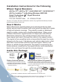
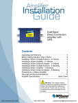
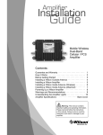
Installation
Guide
Adjustable Gain
Signal Boosters
AG Pro 75™, AG Pro 70™,
AG Pro ZSVInstaller™,
AG SOHO 65™, AG SOHO 60™
(SOHO: Small Office, Home Office)
In-Building Wireless 800/1900 MHz
Smart Technology ™
Contents:
Antenna Options & Accessories . . . . . . . . . . . . . . . . . . . . . . . . . . 1
Quick Install Overview. . . . . . . . . . . . . . . . . . . . . . . . . . . . . . . . . . 2
Installation Diagram. . . . . . . . . . . . . . . . . . . . . . . . . . . . . . . . . . . . 3
Before Getting Started. . . . . . . . . . . . . . . . . . . . . . . . . . . . . . . . . . 4
Finding the Strongest Signal. . . . . . . . . . . . . . . . . . . . . . . . . . . . . 6
Outside Antenna Installation. . . . . . . . . . . . . . . . . . . . . . . . . . . . . 7
Installing the Inside Antenna . . . . . . . . . . . . . . . . . . . . . . . . . . 9
Installing a Wilson Electronics Signal Booster . . . . . . . . . . 9
Powering up a Wilson Electronics Signal Booster. . . . . 10
Understanding the Signal Booster Lights. . . . . . . . . . . 12
Warnings and Recommendations . . . . . . . . . . . . . . . 15
Guarantee & Warranty. . . . . . . . . . . . . . . . . . . . . . . 17
Specifications. . . . . . . . . . . . . . . . . . Back Cover
Note: This manual contains important safety and operating
information. Please read and follow the instructions in this
manual. Failure to do so could be hazardous and result in
damage to your signal booster.
Wilson
®
Electronics, Inc.
Installation Instructions for the Following
Wilson Signal Boosters:
AG Pro 75™, AG Pro 70™, & AG SOHO 65™, AG SOHO 60™
AG Pro Installer™ In-Building Wireless 800/1900
Smart Technology ™ Signal Boosters
Model # 271265
FCC ID: PWO271265 IC: 4726A-271265
The term “IC” before the radio certification number only signifies that Industry Canada
technical specifications were met.
How it Works
Wilson Electronics signal boosters are bi-directional devices that
deliver service levels consistent with what would be expected in areas
of high cell network coverage. They amplify a weak or shadowed
signal in mobile, marine and in-building applications. When using
a Wilson Electronics signal booster in conjunction with Wilson
Electronics antennas, the outside antenna will collect the cell
tower signal and send it through the cable to the signal booster.
The signal is then amplified and re-transmitted through the inside
antenna into the room. Cell phones and cellular data cards in that
area then communicate with the improved signal. When a cell
phone or cellular device transmits, the signal is received by the
inside antenna, amplified by the signal booster and broadcasted
back to the cell tower through the outside antenna.
N Female - FME
Female Adapter
(Sold with the
AG SOHO 60)
Inside this Package
Note: Kits may contain different accessories
AC/DC
Power
Supply
Signal
Booster
(The AG Pro Installer has a
different knob configuration)
Outdoor Antenna Options
Indoor Antenna Options & Accessories
1. 1900 MHz Yagi PCS Antenna (301124)
2. 800 MHz Yagi Cellular Antenna (301129)
3. Wide Band Directional Antenna 700 MHz 2700 MHz (304411)
A. Wide-Band Panel Antenna 700-2700MHz (301155)
B. 50 Ohm Lightning Surge Protector N-Connector (859902)
C. 75 Ohm Lightning Surge Protector F-Connector (859988)
Splitter options on page 3
1
2
3
A
B
C
To purchase, call Wilson Electronics Sales Department at: 800-204-4104
1
Contact Wilson Electronics Technical Support Team with any questions at 507-282-8484
or email: [email protected]. Hours: 7 am to 6 pm MST.
Quick Install Overview
See Installation Diagram on page 3. Contact Wilson Electronics
Technical Support Team with any questions at .
1. Select a location to install the signal booster that is away
from excessive heat, direct sunlight, moisture and has proper
ventilation. Do not place the signal booster in an air-tight
enclosure.
2. Select a location on the roof of the building to install the outside
antenna. Use a cell phone in test mode to find the strongest signal
from the cell tower. Visit www.WilsonElectronics.com to find test
mode function for your particular cell phone. See page 6.
3. Select a location for the inside antenna, preferably in the
center of where the signal needs to be amplified. A minimum
separation distance (combined vertical/horizontal) of 20
feet is necessary for operation. If the inside coverage is not
sufficient you may need as much as 50 feet of separation. See
installation diagram on pages 3 & 4.
4. Run the outside antenna cable to the signal booster and attach
it to the connector labeled “Outside Antenna” on the signal
booster. Run the inside antenna cable to the signal booster
and attach it to the connector labeled “Inside Antenna” on the
signal booster. Note: Be careful when plugging the connectors
in so as not to bend the center pins on the connectors. See
page 8 for more information on running cable.
5. Before powering up the signal booster, verify that both the
outside antenna and the inside antenna are connected and
check that all connections are tight. Lightning surge protection
is recommended for all in-building installations. See page 7.
6. The Signal Booster has been packaged with the gain control
knobs adjusted to the highest gain position. If one or both of
the lights are not green, please refer to pages 12-14.
7. Warning: Connecting the signal booster directly to a cell phone
with use of an adapter will damage the cell phone and the
signal booster.
Contact Wilson Electronics Technical Support Team with any questions at 507-282-8484
or email: [email protected]. Hours: 7 am to 6 pm MST.
2
Installation Diagram
Outside
Antenna
Inside Antenna
Preferred Method: Place the inside
antenna in the ceiling facing down
for the best coverage.
(
i
Note: The inside panel antenna may
be mounted on the wall directly under
the outside antenna, in the null zone,
if 20 feet of vertical separation can be
maintained.
Inside Antenna
Null Zone: The area under
the antenna, where the
antenna radiates the least.
Note: A lightning surge protector is
recommended for all building installations.
Make sure the protector is installed in
line between the outside antenna and the
signal booster.
(Optional
second
antenna for
additional
coverage).
Splitter Options:
3
2-way
3-way
4-way
(859957)
(859980)
(859981)
Typical Installation
Contact Wilson Electronics Technical Support Team with any questions at 507-282-8484
or email: [email protected]. Hours: 7 am to 6 pm MST.
Before Getting Started
This guide will help you properly install your Wilson Electronics
Signal Booster. It is important to read through all of the
installation steps for your particular application prior to
installing any equipment. Read through the instructions,
visualize where all the equipment will need to be installed and do
a soft installation before mounting any equipment. Contact Wilson
Electronics Technical Support with any questions at: .
Splitter
(if using multiple
inside antennas)
Lightning
Surge Protector
Inside Antenna
(Optional
third antenna
for additional
coverage).
Signal
booster
Power
Supply
n
Contact Wilson Electronics Technical Support Team with any questions at 507-282-8484
or email: [email protected]. Hours: 7 am to 6 pm MST.
4
Selecting a Direction for the Outside Antenna
Select a location on the roof of the building to install the outside
antenna. Use a cell phone in test mode to find the strongest signal
from the cell tower. See page 6 for more information. To get the
strongest signal possible, it is very important to set up your outside
antenna properly. The inside and the outside antenna must be
mounted in such a way that they are able to pick up the best possible
cell signal on the outside of the building and provide the best possible
signal on the inside of the building. Mount the outside antenna as
high as possible facing the cell tower in an area with the best possible
signal coverage. Note: Never point the front of a directional antenna
toward the inside antenna. See Figures 1 & 2 on page 11.
Reasons for Weak Cellular Signals
Anyone who uses a cell phone or cellular data card knows the
frustration of not being able to connect to or maintain a strong
cellular signal. When this occurs, it is generally due to one of two
reasons:
1. Location of the Nearest Cell Tower – Cell towers are situated
to provide broad coverage; however, there are many areas in
which signal strength may be reduced by topographic features
or by local government restrictions on the height or placement
of the towers themselves. Rural areas generally have fewer cell
towers than urban regions.
2. Natural and Man-Made Obstructions – Signal strength can
also be negatively affected by trees, hills, buildings, weather,
and other obstructions. You may be relatively close to a cell
tower but still unable to make a call. This often occurs in homes,
offices and other buildings in which stucco, concrete or metal
walls may block the signal.
The Signal Booster works with two antennas. The inside antenna
communicates with your cell phone and the outside antenna
communicates with the cell tower.
5
Contact Wilson Electronics Technical Support Team with any questions at 507-282-8484
or email: [email protected]. Hours: 7 am to 6 pm MST.
The outside antenna receives the cell tower signal and sends it
through the cable to the Signal Booster, where it is amplified and
re-transmitted much stronger through the inside antenna into the
room. When the inside antenna picks up a signal from your cellular
device, the Signal Booster amplifies that signal and transmits it
through the cable to the outside antenna and back to the cell tower.
(Note: The Signal Booster will only operate if there is an adequate
signal to amplify.)
Finding the Strongest Signal
When installing your signal booster’s outside
antenna, aiming it towards the best signal
source from your service provider is important.
The best way of getting the strongest signal
is to have one person on the roof to rotate
the outside antenna, which is connected
to the signal booster, while the second
person is watching the signal strength
on the phone inside the building. This
allows you to read the signal strength
from the cell tower. Turn the outside
antenna about 45 degrees at a time.
It is preferable to have the phone in
the test mode so the actual signal strength can be read as bars
are not the most accurate. Go to www.wpsantennas.com for
help in finding the test mode for your phone. Always make sure the
person inside the building gives the signal time to arrive and register
on the phone. (Between 10-30 seconds for phone to reset to the
new signal reading). Signal readings usually appear as a negative
number (for example, -86). The closer you get to zero the stronger
the signal. (See graph below).
Signal Strength Graph
EXCELLENT
-50dB
-60dB
GOOD
-70dB
-80dB
POOR
-90dB
-100dB
NO
SIGNAL
-110dB
Contact Wilson Electronics Technical Support Team with any questions at 507-282-8484
or email: [email protected]. Hours: 7 am to 6 pm MST.
6
Drip hole on bottom
Cell Tower
Outside Antenna Installation
The antenna should be mounted as shown in the illustration
above. The mounting bracket, included with antenna, is adjustable
and will accommodate pipe diameters from 1.25” to 2” (pipe sold
separately). Mount the antenna so that there is at least 3 feet of
clearance in all directions around it. Position the antenna so that
it has an unobstructed line of sight to the cell tower’s strongest
signal. Make sure the antenna is not pointing across your own roof
or at the inside antenna as this will cause the oscillation protection
circuitry to shut down the signal booster.
Warning: Lightning protection is recommended for all installations
(Part #859902 or 859988). Take extreme care to ensure that
neither you nor the antenna comes near any electric power lines.
Installing Lightning Protection
Install the Lightning Surge
Protector (LSP) close to
the signal booster. Attach
the cable from the outside
antenna to the surge
protector, using a short length
of low loss cable; attach
one end to the LSP and the
other to the outside antenna
connector on the signal
booster. Attach a ground
wire to the LSP. (For AG Pro
70 use Part# 859988 75 Ohm
Lightning Surge Protector).
7
To the outside antenna
Ground Wire
Lightning Surge
Protection
Signal Booster
Contact Wilson Electronics Technical Support Team with any questions at 507-282-8484
or email: [email protected]. Hours: 7 am to 6 pm MST.
Cell Signal
Cell Tower
Outside
Wide Band
Antenna
Mounting Tips for Running Outside
Antenna Cable
If you are mounting the outside antenna on the roof of your building,
we have found that it is easiest to run your cable underneath the
down side of your roof’s flashing. If you have satellite TV service
installed at your home or office, you may be able to follow the same
route as the satellite TV cables that are already running from outside
of your building to the inside.
After routing the cable, we recommend sealing any areas where
the cable passes into the building with silicone or other waterproof
sealant to keep your installation from leaking. If you are mounting
the outside antenna to the outside wall of your home or building, the
simplest way is to run the cable on the outside of the wall and attach
it to the exterior of your home or office. Then drill a hole through the
wall where you want the cable to appear on the inside of the building.
Before drilling, make sure that there are no electrical outlets, sewer or
water pipes, or electrical wiring in the wall that you are about to drill
through as this could potentially harm you or damage the building.
After drilling the required hole, run the cable through and seal it with
cable bushings or a silicon-type sealant to enclose the hole that you
have created. In some instances, it may be possible to run the cable
up into the fascia of the attic overhang. In this circumstance, the cable
will be accessible in the attic for further routing.
Contact Wilson Electronics Technical Support Team with any questions at 507-282-8484
or email: [email protected]. Hours: 7 am to 6 pm MST.
8
Installing the Inside Antenna
Find the desired location for the panel antenna. Verify that the
panel antenna and the outside antenna have the necessary
separation (Minimum of 20 vertical/horizontal feet if installed with
signal booster set at a lower gain, for maximum gain you may
need as much as 50 feet of separation). For optimum results the
antenna should be mounted at least 6 feet off the ground.
Inside
Antenna
Ceiling
Rafters
In some cases, multiple inside antennas may be required, for
instance if you have multiple rooms with poor signal. A signal may
be split by using a splitter. If using more than one inside antenna,
a separation of at least 20 feet is necessary between inside
antennas. See configuration on pages 3 & 4.
Installing a Wilson Electronics Signal Booster
Select a location to install the signal booster that is away from
excessive heat, direct sunlight, moisture and that has proper
ventilation. Do not place the signal booster in an air-tight
enclosure. Recommended installation locations for in-building
signal boosters are:
• On a shelf
• In a closet
• Near a power outlet
Note: It is important to have adequate air ventilation. Maintain at
least 6 inches of clearance from surrounding objects.
Run the outside antenna cable to the signal booster and attach it
to the connector labeled “Outside Antenna” on the signal booster.
Run the inside antenna cable to the signal booster and attach it to
the connector labeled “Inside Antenna” on the signal booster.
9
Contact Wilson Electronics Technical Support Team with any questions at 507-282-8484
or email: [email protected]. Hours: 7 am to 6 pm MST.
Note: For distances of 20 feet or more, use Wilson low loss coax
cable to prevent significant signal loss.
Note: Be careful when plugging the connector in so as not to
damage the center pins on the connectors.
Warning: An inside antenna must have a separation distance
from all persons that is at least 15 inches for the panel antenna.
Powering up a Wilson Electronics
Signal Booster
1. Never point the front of a directional outside antenna toward the
inside antenna. See Figures 1 & 2 on page 11.
2. Ensure that both the outside antenna cable and the inside
antenna cable are connected to the signal booster and the
connections are tight before powering up the signal booster.
3. Plug the 6-volt power supply into the signal booster input marked
“6V DC” (carefully, to avoid damaging the center pin) and then
into a wall outlet.
4. If the signal booster does not have a green light(s), please see
pages 12 & 13. See page 14 for AG Pro Installer.
5. If you know that only one frequency band (800 or 1900) is
available in your coverage area (or going to be used), reduce
the gain control on the frequency band that is NOT in use to the
lowest setting. This will reduce the power consumption of the
signal booster.
6. Using multiple signal boosters in one installation could cause
interference to the cell tower.
7. Contact Wilson Electronics Technical Support Team with any
questions at or email tech@wilsonelectronics..
Technical Support hours are 7 am to 6 pm MST.
Contact Wilson Electronics Technical Support Team with any questions at 507-282-8484
or email: [email protected]. Hours: 7 am to 6 pm MST.
10
Figure 1
CORRECT INSTALLATION
Point antennas away from each other
Outdoor
Antenna
Inside Panel
Antenna
Signal Booster
Figure 2
INCORRECT INSTALLATION
Never point antennas toward each other
Outdoor
Antenna
Inside Panel
Antenna
Signal Booster
11
Contact Wilson Electronics Technical Support Team with any questions at 507-282-8484
or email: [email protected]. Hours: 7 am to 6 pm MST.
Understanding the Signal Booster Lights and
Troubleshooting
During installation mode the signal booster is resetting itself very
quickly to aid the installer. The Signal Booster is equipped with
two indicator lights, one for the 800 MHz band and the other for
the 1900 MHz band. For the first 15 minutes that the booster is
plugged in, it is programed for a test and alignment period. During
this time, both lights will do one of the following 4 things:
Note: If after the initial 15 minutes you are not done with the
installation, the signal booster can be reset and enter installation
mode again by disconnecting and reconnecting the power supply
from the booster.
1. Blinking Green
If the signal booster is blinking green, the signal booster is
operating properly. If you are happy with the coverage area in
your building, then you are done. Blinking will stop after the 15
minute installation period.
2. Blinking Orange
Note: For AG Pro Installer see additional instructions on page
14. If either of the two lights on the signal booster are blinking
orange the signal booster is experiencing receiver overload.
The signal booster has protection shut off circuits to prevent
the disruption of cell towers. If one or both lights are blinking
orange, this indicates that the booster has shut down due to
close proximity to a cell tower. First, turn down the gain control
on the band that is blinking until you get a blinking green light.
The booster is now working with reduced gain. If the gain is
not adequate for good coverage, you will need to turn the gain
to maximum and then turn the outside antenna away from the
cell tower until the light turns to blinking green. If the booster
Contact Wilson Electronics Technical Support Team with any questions at 507-282-8484
or email: [email protected]. Hours: 7 am to 6 pm MST.
12
will not respond turn the gain down 5 dB and move the outside
antenna. Continue to adjust the gain and the antenna position
until the light turns blinking green. Contact Wilson Electronics
Technical Support Team for assistance: 507-282-8484.
3. Solid Red
If either of the two lights on the signal booster are solid red,
this indicates that the signal booster has shut down on that
frequency to prevent an oscillation (feedback). First, make
sure that all the connections are tight. Then reduce the
gain of the booster in small increments by rotating the gain
control, counter clockwise, waiting 5 seconds between each
adjustment for the booster to reset. Continue this adjustment
until the light turns blinking or solid green. When you are
turning down the gain, you are reducing the inside coverage
area. If the amount of coverage area is sufficient for your
needs and the light is green the installation is complete. If the
coverage area is not large enough, it is necessary to increase
the separation distance of the antennas by moving them
horizontally or vertically farther apart, or both. Then increase
the gain until the red light comes on, and then slightly keep
decreasing the gain until the green or blinking green light
appears. If after separating the antennas your coverage area
is still too small, contact Wilson Electronics Technical Support
Team for assistance: .
If your installation takes longer than 15 minutes, it is possible
to re-enter the installation mode by disconnecting and
reconnecting the power supply from the signal booster.
Note: For AG Pro Installer, if you see a solid red light, only use
the downlink (DL) gain controls. Leave the uplink (UL) gain
controls at maximum.
4. SOLID Green
The indicator lights on the signal booster will be a solid green
after the first 15 minute installation period, if the unit is powered
up and working properly.
13
Contact Wilson Electronics Technical Support Team with any questions at 507-282-8484
or email: [email protected]. Hours: 7 am to 6 pm MST.
Additional
Instructions for the
AG Pro Installer™
with separate uplink
and downlink gain
controls
This signal booster is supplied with
separate uplink and downlink gain
controls. Note: All gain controls
should be set to maximum. If you
have green lights, the installation
is complete.
If one or more lights are
blinking orange, the signal
booster is experiencing receiver
overload. Reduce the uplink (UL)
gain control, without reducing the
downlink (DL) gain to eliminate the
overload. This configuration will
eliminate cell tower interference
(overload) without reducing
coverage in the building.
Contact Wilson Electronics Technical Support Team with any questions at 507-282-8484
or email: [email protected]. Hours: 7 am to 6 pm MST.
14
Warnings and Recommendations
Warning:The directional antenna must always be located so
the back or side points to the inside antenna. Never
point the front of the outside antenna toward the
inside antenna – this is to prevent oscillation.
Warning:Connecting the signal booster directly to the cell phone
with use of an adapter will damage the cell phone.
Warning:Use only the power supply provided. Use of a
non-Wilson Electronics product may damage your
equipment.
Warning:RF Safety: FCC regulations require that any fixed
outside antenna used with this signal booster may
not have gain (less cable loss) that exceeds 15
dBi and must be located at least 30 inches from all
people. Inside antennas must not exceed 7 dBi gain
(less cable loss) in the 800 MHz band or 10 dBi gain
(less cable loss) in the 1900 MHz band and must be
located at least 15 inches from all people.
Warning:Verify that both the outside antenna and the inside
antenna are connected to the signal booster before
powering up the signal booster.
Recommendation: 15
Lightning surge protection is recommended
for all in-building installations.
Contact Wilson Electronics Technical Support Team with any questions at 507-282-8484
or email: [email protected]. Hours: 7 am to 6 pm MST.
About Wilson Electronics
Wilson Electronics, Inc. has been a leader in the wireless
communications industry for over 40 years. The company designs
and manufactures signal boosters, antennas and related
components that significantly improve cellular phone signal
reception and transmission in a wide variety of applications, both
mobile and in-building.
With extensive experience in antenna and signal booster research
and design, the company’s engineering team uses a state-of-theart testing laboratory, including an anechoic chamber and network
analyzers, to fine-tune antenna designs and performance. For
its signal boosters, Wilson Electronics uses a double electrically
insulated RF enclosure and cell tower simulators for compliance
testing.
Wilson Electronics signal boosters feature patented Smart
Technology ™ that enables them to automatically adjust their
power based on cell tower requirements. By detecting and
preventing oscillation (feedback), signal overload and interference
with other users, these Smart Technology ™ signal boosters
improve network cell phone areas without compromising carrier
systems.
All products are engineered and assembled in the company’s
55,000-square-foot headquarters in St. George, Utah. Wilson
Electronics has product dealers in all 50 states as well as in
countries around the world.
Contact Wilson Electronics Technical Support Team with any questions at 507-282-8484
or email: [email protected]. Hours: 7 am to 6 pm MST.
16
30-Day Money-Back Guarantee
All Wilson Electronics products are protected by Wilson
Electronics 30-day money-back guarantee. If for any reason the
performance of any product is not acceptable, simply return the
product directly to the reseller with a dated proof of purchase.
1-Year Warranty
Wilson Electronics Signal Boosters are warranted for one (1) year
against defects in workmanship and/or materials. Warranty cases
may be resolved by returning the product directly to the reseller
with a dated proof of purchase.
Signal Boosters may also be returned directly to the manufacturer
at the consumer’s expense, with a dated proof of purchase and a
Returned Material Authorization (RMA) number supplied by Wilson
Electronics. Wilson Electronics shall, at its option, either repair
or replace the product. Wilson Electronics will pay for delivery of
the repaired or replaced product back to the original consumer if
located within the continental U.S.
This warranty does not apply to any signal booster determined
by Wilson Electronics to have been subjected to misuse, abuse,
neglect, or mishandling that alters or damages physical or
electronic properties.
RMA numbers may be obtained by phoning Technical Support at
507-282-8484
.
17
Contact Wilson Electronics Technical Support Team with any questions at 507-282-8484
or email: [email protected]. Hours: 7 am to 6 pm MST.
Disclaimer: The information provided by Wilson Electronics,
Inc. is believed to be complete and accurate. However, no
responsibility is assumed by Wilson Electronics, Inc. for any
business or personal losses arising from its use, or for any
infringements of patents or other rights of third parties that
may result from its use.
Copyright © 2011 Wilson Electronics, Inc. All rights reserved.
Operation is subject to the following two conditions: (1) This
device may not cause interference and (2) this device must accept
any interference, including interference that may cause undesired
operation of this device.
One or more of the following U.S. Patent numbers may apply
to the Signal Booster in this product – D596,614; D596,615;
D563,381;7,729,669; 7,486,929; 7,729,656; 7,409,186; 7,783,318;
7,684,838; 12,714,994.
Contact Wilson Electronics Technical Support Team with any questions at 507-282-8484
or email: [email protected]. Hours: 7 am to 6 pm MST.
18
AG Pro 75™, AG Pro 70™, AG SOHO 60™ & AG SOHO 65™ Specifications
AG Pro 75 &
AG Pro Installer
Specifications
AG Pro 70
Specifications
Antenna connectors
N-Female
Antenna impedance
50 ohms
IC: 4726A-271265
FCC ID: PWO271265
AG SOHO 65
Specifications
AG SOHO 60
Specifications
F-Female
N-Female
FME-Male
75 ohms
50 ohms
50 ohms
Model Number
271265
5.7 x 4.2 x 1.5 inch (14.0 x 10.8 x 3.9 cm)
Dimensions
Weight
1.27 lbs (0.544 kg)
Frequency
1
824-894 MHz / 1850-1990 MHz
Passband Gain (nominal)
800 MHz * 1900 MHz
2
70 dB Typical,
75 dB Maximum
65 dB Typical,
70 dB Maximum
20 dB Bandwidth (nominal)
60 dB Typical,
65 dB Maximum
55 dB Typical
60 dB Typical
Downlink
800 MHz
45 MHz
1900 MHz
88 MHz
Power Output
800 MHz
1900 MHz
Power output for single cell phone (uplink)
30.8 dBm
30.5 dBm
Power output for single received channel (downlink)
26.0 dBm
25.2 dBm
4
Power output for multiple transmitted channels
(uplink)
The maximum power is reduced
by the number of channels:
Maximum Power
Number of channels
800 MHz
1900 MHz
2
24.0 dBm
21.3 dBm
3
20.5 dBm
17.8 dBm
4
18.0 dBm
15.3 dBm
5
16.0 dBm
13.3 dBm
6
14.5 dBm
11.8 dBm
4
Power output for multiple received channels
(downlink)
The maximum power is reduced
by the number of channels:
Noise Figure (typical downlink/uplink)
Isolation
Power Requirements
Maximum Power
Number of channels
800 MHz
1900 MHz
2
24.8 dBm
23.7 dBm
3
21.3 dBm
20.2 dBm
4
18.8 dBm
17.7 dBm
5
16.8 dBm
15.7 dBm
6
15.3 dBm
14.2 dBm
3.5 dB nominal / 6 dB nominal
> 90 dB
110-240 V AC, 50-60 Hz, 8 W
Notes:
1. Nominal gain is the maximum gain at any frequency in the passband.
2. Nominal bandwidth is the difference between two frequencies that are adjacent to the passband where the amplification is 20 dB lower than the passband
amplification. One of the frequencies is lower than the passband and the other is higher.
3. The Manufacturer’s rated output power of this equipment is for single carrier operation. For situations when multiple carrier signals are present, the rating
would have to be reduced by 3.5 dB, especially where the output signal is re-radiated and can cause interference to adjacent band users. This power
reduction is to be by means of input power or gain reduction and not by an attenuator at the output of the device.
4. The maximum power for 2 or more simultaneous signals will be reduced by 6 dB every time the number of signals is doubled.
3301 East Deseret Drive, St. George, UT 84790
For additional Technical Support visit www.WilsonElectronics.com
or email at: tech@wpsantennas.
Phone: 507-282-8484 Local: 507-282-8484 Fax: 866-827-4052
www.twitter.com/WilsonCellular
www.facebook.com/WilsonCellular
AIG #110769 - Rev006 - 06/10/11