1
BCP-8W
BCP-8X
AND
+<'521,&6(48(1&,1*%2,/(5&21752/$1'(;7(16,21
,167$//$7,21$1'23(5$7,21,16758&7,2160$18$/
86(523(5$7,21,16758&7,2160$18$/
BCP-8W
HYDRONIC SEQUENCING CONTROL
SYS=144F OD=35F
Stage A
Stage E
SYSTEM
Stage B
Stage F
DHW PUMP
Stage C
Stage G
COMB. AIR
Stage D
Stage H
ENCLOSED
ENERGY
MANAGEMENT
EQUIPMENT
OUTPUT RATING: 2A, 120VAC.
MAXIMUM 15A TOTAL FOR ALL CIRCUITS
LISTED
99RA
C
<AB > DE
HI
LO
STAGE
GH
JK
-- OFF
MENU
US
INPUT RATINGS: 120VAC 60Hz, 12VA MAX
CAUTION: Risk of Electric Shock.
PWR
Use Copper Conductors Only.
PROGRAM
L N
Stage A Stage B Stage C Stage D Stage E Stage F
DHW COMB.
Stage G Stage H SYSTEM PUMP
AIR
1 2
3 4 5 6 7 8 9 10 11 12 13 14
15 16 17 18 19 20 21 22 23 24
:$51,1*
DO NOT APPLY ANY VOLTAGE
TO INPUT TERMINALS
RUN
AUX 1
SHUTDOWN
/TSTAT PROVE
TEMP OUTDOORRETURN DHW
TEMP TEMP
/SETBACK
RS485
25 26 27 28 29 30 31 32 33 34 35 36 37 38
7KLV:HLO0F/DLQFRQWUROLVVWULFWO\DQRSHUDWLQJFRQWUROLWVKRXOGQHYHUEHXVHGDVD
SULPDU\OLPLWRUVDIHW\FRQWURO$OOHTXLSPHQWPXVWKDYHLWVRZQFHUWLILHGOLPLWDQGVDIHW\
FRQWUROVUHTXLUHGE\ORFDOFRGHV7KHLQVWDOOHUPXVWYHULI\SURSHURSHUDWLRQDQGFRUUHFWDQ\
VDIHW\SUREOHPVSULRUWRWKHLQVWDOODWLRQRIWKLV:HLO0F/DLQFRQWURO
Part Number 550-100-071/0408
%&3:,QVWDOODWLRQDQG2SHUDWLRQ0DQXDO
&RQWHQWV
%&3:/$<287 3
%&3:29(59,(: 4
81'(567$1',1*23(5$7,21&21&(37 5
Reset Ratio/Outdoor Reset . . . . . . . . . . . . . . . . 5
PID Operation . . . . . . . . . . . . . . . . . . . . . . . 6
OSS Operation . . . . . . . . . . . . . . . . . . . . . . 6
0DNH6XUH<RX+DYHWKH5LJKW&RQWURO 7
,1,7,$/6(783 7
6HOHFWLQJWKH6\VWHP)HDWXUHV 7
,167$//$7,21 0RXQWLQJWKH(QFORVXUH ,QVWDOOWKH6HQVRUV 9
System Sensor Installation . . . . . . . . . . . . . . . . 9
Outdoor Sensor Installation . . . . . . . . . . . . . . . . 9
:LULQJ 10
Wiring the Power (Terminals 1, 2) . . . . . . . . . . . . 10
Wiring the Sensors . . . . . . . . . . . . . . . . . . . 10
Wiring the Domestic Hot Water (DHW) Sensor (Terminals 33,
34) . . . . . . . . . . . . . . . . . . . . . . . . . . . . 11
Wiring the Shutdown (Terminals 35, 36) . . . . . . . . 11
Wiring the T-STAT (Terminals 35, 36) . . . . . . . . . . 11
Wiring the Setback (Terminals 35, 36) . . . . . . . . . 11
Connecting to the BCP-8X Panels and 420MOD Interface13
Selecting the BCP-8X Panel Letter . . . . . . . . . . . 13
,167$//(50(186(48(1&( 14
6WDUWXS6HWWLQJV 17
Program Change Settings . . . . . . . . . . . . . . . . 17
Startup Sequence . . . . . . . . . . . . . . . . . . . . 17
Control Mode . . . . . . . . . . . . . . . . . . . . . . 17
Display Unit . . . . . . . . . . . . . . . . . . . . . . . 17
Setting the 4mA and 20mA Set Points (Available in 4-20mA
EMS only) . . . . . . . . . . . . . . . . . . . . . . . . 17
DHW Piping . . . . . . . . . . . . . . . . . . . . . . . 18
DHW Pump Output . . . . . . . . . . . . . . . . . . . 18
Combustion Air Damper Output . . . . . . . . . . . . . 18
External Input Mode . . . . . . . . . . . . . . . . . . . 18
Burner Type . . . . . . . . . . . . . . . . . . . . . . . 19
Boiler Output . . . . . . . . . . . . . . . . . . . . . . 19
Total Boilers . . . . . . . . . . . . . . . . . . . . . . . 19
Staging . . . . . . . . . . . . . . . . . . . . . . . . . 19
Sequence . . . . . . . . . . . . . . . . . . . . . . . . 19
Control Logic . . . . . . . . . . . . . . . . . . . . . . 19
Sensor Fault . . . . . . . . . . . . . . . . . . . . . . . 20
6HWWLQJWKH&RQWUROWR)DFWRU\'HIDXOWV 20
2SHUDWLQJ6HWWLQJV 20
Program Change Settings . . . . . . . . . . . . . . . . 20
Season . . . . . . . . . . . . . . . . . . . . . . . . . 21
Reset Ratio . . . . . . . . . . . . . . . . . . . . . . . 21
Customized Reset Ratio. . . . . . . . . . . . . . . . . 21
Set Point (Not Adjustable in EMS Mode) . . . . . . . . 22
Outdoor Cutoff Temperature. . . . . . . . . . . . . . . 22
Target Offset. . . . . . . . . . . . . . . . . . . . . . . 22
Minimum Target . . . . . . . . . . . . . . . . . . . . . 23
2
Maximum Target. . . . . . . . . . . . . . . . . . . . . 23
%RLOHU0LQLPXP5HWXUQ 23
Minimum Return . . . . . . . . . . . . . . . . . . . . . 23
Return Lag. . . . . . . . . . . . . . . . . . . . . . . . 24
6\VWHP6HWWLQJV 24
Program Change Settings . . . . . . . . . . . . . . . . 24
6WDJH6HWWLQJV 24
Reaction Time . . . . . . . . . . . . . . . . . . . . . . 24
Purge Delay . . . . . . . . . . . . . . . . . . . . . . . 24
Minimum Runtime . . . . . . . . . . . . . . . . . . . . 24
Standby Delay . . . . . . . . . . . . . . . . . . . . . . 25
Last Stage Hold . . . . . . . . . . . . . . . . . . . . . 25
Throttle Range. . . . . . . . . . . . . . . . . . . . . . 25
/HDG6HWWLQJV 25
Lead Boiler . . . . . . . . . . . . . . . . . . . . . . . 26
Rotate Mode. . . . . . . . . . . . . . . . . . . . . . . 26
6HWEDFN6FKHGXOH 26
Setback . . . . . . . . . . . . . . . . . . . . . . . . . 26
Boost . . . . . . . . . . . . . . . . . . . . . . . . . . 26
Boost Period. . . . . . . . . . . . . . . . . . . . . . . 27
Day/Night Schedules . . . . . . . . . . . . . . . . . . 27
Set Present Time . . . . . . . . . . . . . . . . . . . . 27
'+:6HWWLQJV 2
DHW Priority Timer (Available with Parallel DHW Piping)28
DHW Set Point (Requires an Optional DHW Temperature
Sensor) . . . . . . . . . . . . . . . . . . . . . . . . . 28
3XPS9DOYHDQG&RPEXVWLRQ$LU'DPSHU2SHUDWLRQ 29
Run-On . . . . . . . . . . . . . . . . . . . . . . . . . 29
Pump Exercise . . . . . . . . . . . . . . . . . . . . . 29
0DLQWHQDQFH 30
System & Outdoor Sensor Trim . . . . . . . . . . . . . 30
+LVWRU\ 30
&RQ¿JXUDWLRQ . . . . . . . . . . . . . . . . . . . . . . 30
Display and Buttons . . . . . . . . . . . . . . . . . . . 30
%RLOHU6HWWLQJV 32
Mode . . . . . . . . . . . . . . . . . . . . . . . . . . 32
RunTime. . . . . . . . . . . . . . . . . . . . . . . . . 32
7528%/(6+227,1* 33
08/7,3/(%2,/(56:,7+380363,3,1*:,5,1*
',$*5$06 34
86(50(186(48(1&( 35
Program Change Settings . . . . . . . .
Season . . . . . . . . . . . . . . . . .
Set Point (Not Adjustable in EMS Mode)
Reset Ratio . . . . . . . . . . . . . . .
Customized Reset Ratio. . . . . . . . .
Outdoor Cutoff Temperature. . . . . . .
Setback . . . . . . . . . . . . . . . . .
Day/Night Schedules . . . . . . . . . .
.
.
.
.
.
.
.
.
.
.
.
.
.
.
.
.
.
.
.
.
.
.
.
.
.
.
.
.
.
.
.
.
.
.
.
.
.
.
.
.
.
.
.
.
.
.
.
.
.
.
.
.
.
.
.
.
.
.
.
.
.
.
.
.
35
35
36
36
36
37
37
37
63(&,),&$7,216 40
%&3:6SHFL¿FDWLRQV 40
%&3;6SHFL¿FDWLRQV 40
%&3:,QVWDOODWLRQDQG2SHUDWLRQ0DQXDO
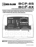
%&3:/$<287
Program Switch to restrict access
to function changes. This Switch is
covered with Enclosure Wiring Cover.
LEDs indicate
associated relay’s status
Button function is presented on
bottom row of the display.
BCP-8W
HYDRONIC SEQUENCING CONTROL
SYS=144F
Stage A
Stage E
SYSTEM
Stage B
Stage F
DHW PUMP
Stage C
Stage G
COMB. AIR
Stage D
Stage H
C
OUTPUT RATING: 2A, 120VAC.
MAXIMUM 15A TOTAL FOR ALL CIRCUITS
PWR
L N
1 2
Use Copper Conductors Only.
STAGE
PROGRAM
DHW
PUMP
DO NOT APPLY ANY VOLTAGE
TO INPUT TERMINALS
RUN
COMB.
AIR
3 4
15 16 17 18 19 20 21 22 23 24
Output Relays to manage the stages.
MENU
LISTED
99RA
Stage G Stage H SYSTEM
9 10 11 12 13 14
JK
OFF
US
Stage A Stage B Stage C Stage D Stage E Stage F
5 6 7 8
GH
--
ENCLOSED
ENERGY
MANAGEMENT
EQUIPMENT
INPUT RATINGS: 120VAC 60Hz, 12VA MAX
CAUTION: Risk of Electric Shock.
<AB > DE
HI
LO
OD=35F
PRESS
+
-
TEMP
OUTDOOR RETURN
TEMP
TEMP
DHW
SHUTDOWN
/TSTAT
/SETBACK
RS485
PROVE
25 26 27 28 29 30 31 32 33 34 35 36 37 38
When connecting Temperature Sensors, no
Polarity is observed. Prove terminals
must be connected for BCP-8 to
operate stages.
System Output controls pumps,
valves, or other system components.
DHW Pump and Comb. Air relays are
controlled when configured.
Connect to Extension panels to
add additional stages or connect
to 420MOD Interface for
external set point.
3
%&3:,QVWDOODWLRQDQG2SHUDWLRQ0DQXDO
%&3:29(59,(:
6(48(1&(6837267$*(6:,7+38036259$/9(6
The BCP-8W is the perfect control whenever multiple boiler stages are required for Hydronic heating applications. The BCP-8W controls
the stages and their pumps or valves to maintain a precise system set point.
3,'2529(56,=('6<67(0266/2*,&
The BCP-8W’s control algorithm allows it to look at the rate of change in the system. If the load is changing quickly, the BCP-8W can
be set to OSS sequencing where it will react based on load changes. If the system oscillation is minimal as in heating applications, the
%&3:ZLOOPDNHVORZDQGJUDGXDORXWSXWDGMXVWPHQWV7KHUHIRUHWKH%&3:DGDSWVWRVSHFL¿FV\VWHPUHTXLUHPHQWVDQGPLQLPL]HV
oscillation around the set point.
',*,7$/',63/$<2)$//6<67(06(77,1*6
The BCP-8W’s alphanumeric digital display names each system parameter in simple English and shows its precise value. The easy to
IROORZPHQXV\VWHPDOORZVXVHUVWRTXLFNO\PDNHFKDQJHVWRDQ\V\VWHPVHWWLQJZLWKRXWKDYLQJWROHDUQDQ\VSHFLDOL]HGFRGHVRUNH\
commands.
$8720$7,&527$7,21$021*67$*(6
5RWDWLQJWKH¿UVWVWDJHWREHDFWLYDWHGRQDFDOOIRURXWSXWSURPRWHVHYHQZHDURQHDFKERLOHU7KH%&3:KDVWKUHHPRGHVRIURWDWLRQ
Manual, First-On/First-Off (FOFO), or Time. The Time rotates the lead stage every selected period from every hour to every 41 days.
287'2255(6(7:,7+&86720,=$%/(&859(
With its Outdoor reset feature, the BCP-8W is capable of changing its temperature target based on the outdoor temperature. It offers
VHYHUDOSDUDPHWHUVWKDWFDQEHXVHGWR¿QHWXQHWKHUHVHWFXUYHOffset, Minimum, and Maximum Targets, and Night Setback Schedule
or Setback using an External Signal. )XUWKHUPRUHDFXVWRPL]DEOHRXWGRRUUHVHWFXUYHKDVEHHQLQFRUSRUDWHGIRUXQLTXHDSSOLFDWLRQV
ZKHUHVWDQGDUGUHVHWUDWLRVZLOOQRWVXI¿FH
67$1'%<%2,/(5237,21
$Q\RIWKH%&3:KHDWLQJERLOHUVFDQEHFRQ¿JXUHGDVD6WDQGE\ZLWKDQDGMXVWDEOH6WDQGE\GHOD\$VVLJQLQJDVSHFL¿FERLOHUWR
work in standby mode will remove it from the rotation. In this mode, the boiler will be used for backup in large demand periods where
WKHSULPDU\ERLOHUVZLOOQRWVXI¿FH
6<67(0$1'&20%867,21$,5'$03(52873876:,7+3529(,1387
These outputs work with the control logic to operate a primary system pump and a combustion air damper. In addition, a System Prove
LQSXWFDQEHZLUHGLQWRFKHFNWKHVWDWXVRIHLWKHURIWKHFRPSRQHQWVHQHUJL]HGE\WKHRXWSXWVEHIRUHWKHVWDJHVFDQEHDFWLYDWHG
1250$//2+,/2+,253$5$//(//2/2+,+,6(48(1&,1*
The BCP-8W can sequence boilers as needed)RUKHDWLQJV\VWHPVZKHUHKLJKHUHI¿FLHQF\LVDFKLHYHGXVLQJORZHU¿ULQJVWDJHVWKH
%&3:RIIHUVWKH3DUDOOHO6HTXHQFLQJRSWLRQ,WVHTXHQFHVDOOWKHORZ¿ULQJVWDJHV¿UVWEHIRUHEULQJLQJWKHUHVWRIWKHVWDJHVRQ)RU
other types of boilers, using the Normal Sequencing option brings the lower operating stage followed by the higher one of the lead boiler.
That will be repeated for each of the lag boilers.
08/7,3/(256,1*/(67$*,1*
8QOLNHPDQ\ERLOHUVZKHUHWR¿UHDPXOWLVWDJHERLOHUERWKORZDQGKLJKVWDJHUHOD\VPXVWEHHQHUJL]HGVRPHRIWKHDYDLODEOHHTXLSPHQW
require that the operation of the higher stages turn off the lower operating stages. This can be achieved by selecting Single from the
Startup Staging menu.
$''837267$*(6
As a stand-alone, the BCP-8W-8 is designed to control eight stages. However, it has the capability of expanding its control to two
extension panels (BCP-8X) each with eight stages. Thus, the BCP-8W can control a total of up to 24 stages.
021,7256<67(05(78517(03(5$785(
Using a smart algorithm, the BCP-8W can monitor the boiler return temperature using an optional return sensor mounted on the return
line. Then, sequence the boilers to raise the return temperature above an adjustable Minimum Return.
'+:3803&21752/:,7+08/7,3/(35,25,7<237,216
Having a DHW input either as a dry contact to be used with an external aquastat or as a temperature sensor that can be ordered separately,
the BCP-8W can control a DHW pump using its built-in DHW Pump output relay. The user will have different priority options that
varies based on the DHW piping design.
4
%&3:,QVWDOODWLRQDQG2SHUDWLRQ0DQXDO
81'(567$1',1*23(5$7,21&21&(37
1:4 1:3
1:2
1:1.5
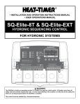
In Outdoor Reset, the BCP-8W controls a hot water heating system to provide a building with
comfortable and even heat levels. The BCP-8W varies the Target temperature of the circulating
heating water in response to changes in the outdoor temperature.
The BCP-8W also controls the system circulating pump with an adjustable Outdoor Cutoff.
When the outdoor temperature is above the Outdoor Cutoff, the System Pump will be off
and no heating water is circulated through the system. When the outdoor temperature drops
EHORZWKH2XWGRRU&XWRIIWKHV\VWHPSXPSUHOD\LVHQHUJL]HGDQGWKHKHDWLQJZDWHUVWDUWVWR
circulate through the system. The temperature of the heating water is controlled by the Reset
Ratio parameters or the Set Point.
(S) Water Temperature (in °F)
220
The BCP-8W has multiple operating modes that satisfy most hydronic systems. When the
Outdoor Reset is selected, it can change the System Set Point based on outdoor temperature.
Or, it can be set to Set Point and sequence stages to achieve a manually adjusted Set Point.
1:1.25
210
200
1:1
190
180
1.25:1
170
1.5:1
160
150
2:1
140
3:1
130
4:1
120
8:1
110
100
70
60
50
40
30
20
10
0
-10
-20
(O) Outdoor Temperature (in °F)
Reset Ratio is Presented as
Outdoor Temp.(O) : Water Temp.(S) Ratio
5(6(75$7,2287'2255(6(7
Each building has different heat loss characteristics. A very well insulated building will
QRWORVHPXFKKHDWWRWKHRXWVLGHDLUDQGPD\QHHGD5HVHW5DWLRRI2'
6<62XWGRRU:DWHU7KLVPHDQVWKHRXWGRRUWHPSHUDWXUHZRXOGKDYHWRGURS
degrees to increase the water temperature 1 degree. On the other hand, a poorly insulated
EXLOGLQJZLWKLQVXI¿FLHQWUDGLDWLRQPD\QHHGD5HVHW5DWLRRI2'6<6
This means that for each degree the outdoor temperature dropped the water temperature
will increase 2 degrees. The BCP-8W has a full range of Reset Ratios to match any
buildings heat loss characteristics.
A heating curve that relies not only on Outdoor temperature but also on the type of
radiation will improve heat comfort. The following are suggested initial settings for
different types of radiation based on average building insulation and heat loss. The
FRQWUDFWRUFDQ¿QHWXQHWKHVHDGMXVWPHQWVEDVHGRQWKHVSHFL¿FEXLOGLQJQHHG
Water Tem perature
With a -20° Offset, the
ratio curves begin at
80° Water Temperature.
1:4
130
1:1
120
110
100
4:1
70
60
50
40
Outdoor Temperature
1:4
110
1:1
100
90
-20 Offset
4:1
80 70
60
50
40
Outdoor Temperature
With a +20° Offset, the
ratio curves begin at
120° Water Temperature.
Water Temperature
7KHVWDUWLQJSRLQWIRUPRVWV\VWHPVLVWKH2'6<62XWGRRU7HPSHUDWXUH
+HDWLQJ:DWHU7HPSHUDWXUHUDWLR7KLVPHDQVWKDWIRUHYHU\GHJUHHWKHRXWGRRU
temperature drops, the temperature of the heating water will increase one degree. The
starting point of the curves is adjustable, but comes factory selected at 70°F Outdoor
Temp. and 100°):DWHU7HPS)RUH[DPSOHZLWKD2'6<6UDWLRLIWKH
outdoor temperature is 50°F, this means the temperature has fallen 20° from the starting
point of 70°F. Therefore, the heating water temperature will increase 20° to 120°F.
With a 0° Offset, the
ratio curves begin at
100° Water Temperature.
Water Temperature
Reset Ratio Curves
When a building is being heated, heat escapes through the walls, doors, and windows to
the colder outside air. The colder the outside temperature, the more heat escapes. If you
can input heat into the building at the same rate that it is lost out of the building, then the
building temperatures will remain constant. The Reset Ratio is an adjustment that lets
you achieve this equilibrium between heat input and heat loss.
150
1:4
1:1
140
130
4:1
120
90
+20 Offset
100
70
60
50
40
Outdoor Temperature
7\SHRI5DGLDWLRQLQ%XLOGLQJ
5HVHW5DWLR
2IIVHW
Radiators (Steel & Cast Iron)
1.00 (OD) : 1.00 (SYS)
Û)
Baseboard (Finned copper tube& Cast Iron)
1.00 (OD) : 1.00 (SYS)
Û)
Radiant (High Mass/Concrete)
4.00 (OD) : 1.00 (SYS)
Û)
Radiant (Low Mass/Joists)
2.00 (OD) : 1.00 (SYS)
Û)
Fan Coils & Air Handlers
1.00 (OD) : 1.00 (SYS)
Û)
:$51,1*
:KHQFRQWUROOLQJDQRQFRQGHQVLQJ
ERLOHUWKH0LQLPXP7DUJHW
WHPSHUDWXUHPXVWEHVHWWRWKHERLOHU
PDQXIDFWXUHUVSHFL¿FDWLRQV,QWKDW
FDVHV\VWHPWHPSHUDWXUHPXVWQRW
JREHORZVXFKWHPSHUDWXUH
5
%&3:,QVWDOODWLRQDQG2SHUDWLRQ0DQXDO
The BCP-8W has multiple operating modes that satisfy most hydronic systems. It can sequence stages to achieve an adjustable Set Point
or an Outdoor Reset Ratio. Moreover, when used with the 420MOD Interface it can accept a 4-20mA signal as a set point. The 420MOD
Interface must be purchased separately. This gives the BCP-8W the capability of being controlled remotely.
3,'23(5$7,21
3,'FRQWUROORJLFLVSULPDULO\XVHGIRUEXLOGLQJKHDWLQJ7KHORJLFZLOOXWLOL]HWZRSULPDU\VHWWLQJVWRDGGRUVXEWUDFWVWDJHV7KH5HDFWLRQ
7LPHLVXVHGWRWXUQRQHQHUJL]HVWDJHV2QWKHRWKHUKDQGWKH0LQLPXP5XQWLPHLVXVHGWRWXUQRIIGHHQHUJL]HVWDJHV$FDOOIRUKHDW
by either closing the TSTAT input or opening the SHUTDOWN input, and when the outdoor temperature is below the Outdoor Cutoff, the
%&3:ZLOOWXUQRQHQHUJL]HWKHORZHVW¿ULQJVWDJHRIWKH/HDG%RLOHUWRVWDUWWKH3XUJH'HOD\$IWHUWKHHODSVHRIWKHSXUJHSHULRGWKH
BCP-8W will start calculating the Reaction Period. If after a full Reaction Time the control logic foresee additional stages are needed,
WKH%&3:ZLOOHQHUJL]HWKHIROORZLQJVWDJH,IWKDWVWDJHZDVDQRWKHUERLOHUWKDWERLOHUKDVWRJRWKURXJKDIXOO3XUJH'HOD\EHIRUH
VWDUWLQJWRFDOFXODWHWKH5HDFWLRQ7LPHIRUWKDWVWDJH2WKHUZLVHLIWKHQH[WVWDJHZDVWKHKLJKHU¿ULQJVWDJHRQWKHVDPHERLOHUWKH
5HDFWLRQ7LPHZLOOVWDUWIURPWKHPRPHQWWKHKLJKHU¿ULQJVWDJHUHOD\LVHQHUJL]HG
When the BCP-8W PID logic foresees that the system will overshoot, regardless of the current system and target values, it will make sure
WKDWWKHODVWVWDJHWXUQHGRQHQHUJL]HGHODSVHGDIXOO0LQLPXP5XQWLPHEHIRUHLWLVWXUQHGRIIGHHQHUJL]HG([FHSWIRUWKHOHDGVWDJH
QRDGGLWLRQDOVWDJHVZLOOEHWXUQHGRIIGHHQHUJL]HGXQWLODQRWKHUIXOO0LQLPXP5XQWLPHLVHODSVHG2QWKHRWKHUKDQGLIWKHODVWVWDJH
LVDOHDGVWDJHLWZLOOUHPDLQHQHUJL]HGXQWLOWKHV\VWHPUHDGLQJH[FHHGVWKHWDUJHWVHWSRLQWE\WKH/DVW6WDJH+ROGYDOXHLQDGGLWLRQWR
satisfying the Minimum Runtime condition. That is, if the Set Point was 150°)DQGWKH/DVW6WDJH+ROGZDVVHWWR°F, the lead stage
ZLOOUHPDLQHQHUJL]HGXQWLOWKHV\VWHPUHDFKHV°F and a full Minimum Runtime elapses. This is useful in protecting the lead stages
from short cycling.
26623(5$7,21
266LVXVHGLQIDVWUHDFWLQJDSSOLFDWLRQDVLQSURFHVVDSSOLFDWLRQVZKHUHPDLQWDLQLQJDVHWSRLQWLVFULWLFDO7KH266XWLOL]HVWKH7KURWWOH
setting, as a mean to calculate the number of stages the BCP-8W shall have on at any point. For every Throttle Range below the set
SRLQWDQDGGLWLRQDOVWDJHVKDOOEHWXUQHGRQHQHUJL]HG7KDWLVLIWKHVHWSRLQWZDV°F and the Throttle setting was 5°F, if the System
dropped below 175°F (180°F - 5°)WKHOHDGVWDJHZLOOHQHUJL]H:LWKIXUWKHUGHFUHDVHLQWKHV\VWHPYDOXHWR°F (180°F - 5°F - 5°F),
WKHVHFRQGVWDJHZLOOHQHUJL]H
As the system temperature rises towards the set point, stages will turn off. Using the previous example, when the system rise to 175°F
ERLOHU%ZLOOGHHQHUJL]HOHDYLQJRQO\ERLOHU$RQ%RLOHU$ZLOOUHPDLQRQXQWLOWKHV\VWHPULVHVDRQHIXOO7KURWWOHUDQJHDERYHWKHVHW
point. This will leave the lead boiler A on until the temperature rises to 185°)WKHQWXUQRIIGHHQHUJL]H
7KURWWOLQJ([DPSOH
6HW3RLQW °)
7KURWWOLQJ °)
%RLOHU6WDJHV$%&DQG'
)DOOLQJ7HPSHUDWXUH
6
7HPSHUDWXUH
&DOFXODWLRQ
6WDJH7XUQHG2Q
6WDJHV2Q
185°F
180 + (1)THR
---
180°F
180 - (0)THR
---
5LVLQJ7HPSHUDWXUH
6WDJH7XUQHG2II
6WDJHV2Q
None
A
None
None
---
A
175°F
180 - (1)THR
A
A
B
A
171 to 174°F
---
---
A
---
A,B
170°F
180 - (2)THR
B
A,B
C
A,B
166 to 169°F
---
---
A,B
---
A,B,C
165°F
180 - (3)THR
C
A,B,C
D
A,B,C
161 to 165°F
---
---
A,B,C
---
A,B,C,D
160°F
180 - (4)THR
D
A,B,C,D
---
A,B,C,D
%&3:,QVWDOODWLRQDQG2SHUDWLRQ0DQXDO
0$.(685(<28+$9(7+(5,*+7&21752/
,I\RXQHHGWKH%&3:WRGRDGGLWLRQDOWDVNVWKDWHLWKHUDUHQRWOLVWHGRUGRQRWNQRZKRZWRVHWWKHPFRQWDFW:HLO0F/DLQ
,1,7,$/6(783
+DYLQJDQ,QLWLDO6HWXS3URJUDPZLOOHDVHWKHFRQ¿JXUDWLRQRIWKH%&3:DQGZLOOSURYLGHWKHRSSRUWXQLW\WRXWLOL]HPDQ\RIWKHHQHUJ\
saving features and give more comfortable heat when needed.
7KHSURJUDPVKRXOGFRQVLVWRIWKHIROORZLQJ
HOHFWLQJWKHIHDWXUHVWKDW\RXUV\VWHPFDQXWLOL]H
6
,QVWDOODWLRQ,QVWDOOWKH&RQWUROVZLWFKHVDQGVHQVRUV
6HWWLQJWKH6\VWHP6WDUWXS
6HWWLQJWKH6\VWHP6HWWLQJV
6HWWLQJWKH6WDJHV
$GMXVWLQJ5HVHW5DWLRDQG:DWHU2IIVHW,Q5HVHW0RGH2QO\
6(/(&7,1*7+(6<67(0)($785(6
The BCP-8W has been designed with Hydronic heating as the primary purpose. With this in mind, many of the BCP-8W features can
EHXWLOL]HGWRHDVHHQKDQFHDQGLPSURYH\RXUV\VWHPSHUIRUPDQFH6RPHRIWKHVHIHDWXUHVDUHOLVWHGLQWKLVVHFWLRQ
+($7,1*:,7+08/7,3/(256,1*/(287387$7$7,0(
7KH%&3:LVHTXLSSHGWRFRQWUROPXOWLSOHPXOWLVWDJHERLOHUVZLWKRUZLWKRXWSXPSVRUYDOYHVIRUKHDWLQJDSSOLFDWLRQV
7KDWFRPELQHGZLWKWKHFDSDELOLW\RIHQHUJL]LQJRQO\DVLQJOHVWDJHRIDPXOWLVWDJHERLOHUZKHQLQKLJKGHPDQGPDNHVWKH%&3
8W versatile for many industries.
287'2255(6(76(732,1725(;7(51$/0$6(732,17
7KH%&3:FDQFRQWUROWKH6\VWHP7HPSHUDWXUHHLWKHUE\DGMXVWLQJWKHWDUJHWDFFRUGLQJWRWKH2XWGRRU7HPSHUDWXUH2XWGRRU
Reset) or by maintaining an adjustable Set Point. The Outdoor Reset option uses an Outdoor Sensor (supplied with the control) and
achieves better fuel savings in addition to better comfort.
8VLQJWKHRSWLRQDO02',QWHUIDFHWKH%&3:FDQUHFHLYHDQH[WHUQDOVHWSRLQWWKURXJKDQ(06V\VWHP
3,'25266&21752//2*,&
7KH%&3:3,'FDQEHXVHGIRUDSSOLFDWLRQVZKHUHV\VWHPUHDFWLRQis slow and requires a long period to achieve or measure the
results. However, OSS, can be used for applications where the load changes frequently and the sequencing must match the load and
its immediate change.
180%(52)67$*(6
7KH%&3:FDQEHFRQ¿JXUHGWRFRQWUROXSWRHLJKWVWDJHV,WFDQFRQWUROXSWRVWDJHVXVLQJDPD[LPXPRIWZR%&3;
Extension Panels, each with eight stages.
67$*(38036259$/9(6
7KH%&3:FDQFRQWUROPXOWLSOHVWDJHVLQDGGLWLRQWR boiler pumps or valves.
&21752/'+:3803$1'&20%867,21$,5'$03(5
The control of the DHW is based on either a temperature sensor, can be purchased separately, on the DHW source or using a dry
contact from an aquastat. The BCP-8W provides multiple DHW Priority options based on the DHW piping. The Combustion Air
Damper output can be used in conjunction with the PROVE input to check the status of the Combustion Air Damper's End Switch,
6\VWHP3XPS
V)ORZ6ZLWFKRUDQ\RWKHURSHUDWLQJGHYLFHEHIRUHDQ\VWDJHLVHQHUJL]HG
021,725%2,/(55(7851
The optional return line sensor, is purchased separately, can be connected to monitor and help protect the boilers from thermal
shock and condensation caused by cool returns.
7
%&3:,QVWDOODWLRQDQG2SHUDWLRQ0DQXDO
$8720$7,&527$7,21$021*%2,/(56
5RWDWLQJWKHOHDGERLOHUWREHDFWLYDWHGRQDFDOOIRURXWSXWSURPRWHVHYHQZHDURQDOOERLOHUV7KH%&3:KDVWKUHHPRGHVRI
URWDWLRQ0DQXDO)LUVW2Q)LUVW2IIRU7LPHG5RWDWLRQ7KLVRSWLRQDXWRPDWLFDOO\URWDWHVWKHERLOHUVHYHU\VHOHFWHGSHULRGIURP
one hour to every 41 days (999 hours).
6(7%$&.%226725'$<1,*+76&+('8/,1*
7ZR6HWEDFNPRGHVDUHDYDLODEOHIRUWKH%&3:
The Day/Night Scheduling provides an adjustable time-based schedule for the Setback. It will be available when Shutdown or Tstat
is selected from the External Input Startup menu options.
:hen Setback is selected from the External Input Startup menu options, an external signal can be used to switch the operation of
the BCP-8W in and out of setback mode
7KH%RRVWFDQEHXVHGWREULQJWKHEXLOGLQJWRFRPIRUWDEOHWHPSHUDWXUHVHWWLQJVDIWHUD1LJKWRU6HWEDFNSHULRG,WGRHVWKDWE\
increasing the target temperature for an adjustable period that follows the setback.
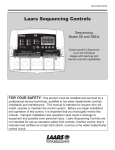
Enclosure Display Module
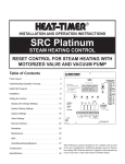
,167$//$7,21
Each of the BCP-8W and BCP-8X consists of three primary enclosure
components.
7KH(QFORVXUH'LVSOD\0RGXOHFRQWDLQVWKHGLVSOD\EXWWRQV/('V
and electric wiring terminals. It has two screws to hold it to the base. A
SURJUDPFRQ¿JXUDWLRQVZLWFKXVHGWRDGMXVW%&3:VHWWLQJVLVSODFHG
above the terminals. This switch is enclosed with the Enclosure Wiring
Cover for security. The wiring terminals are of the plug-in type to ease
installation and removal.
7KH(QFORVXUH%DVH contains the holes to mount and hold the control
DJDLQVWWKHZDOORUDQ\ÀDWVXUIDFH$OORWKHUHQFORVXUHFRPSRQHQWVPRXQW
on the base. The bottom section of the Enclosure Base contains the wiring
chamber with knockouts on the bottom to ease installation.
7KH(QFORVXUH:LULQJ&RYHU seals the wires from the external
environment. It has two screws to hold it to the base and a hole to secure
a lock on the wiring enclosure. A plastic web that separates the wiring
chamber into high and low volt sections has been provided.
02817,1*7+((1&/2685(
Enclosure Wiring Cover
Mounting Base
HOHFWDORFDWLRQQHDUWKHHTXLSPHQWWREHFRQWUROOHG
6
7KHVXUIDFHVKRXOGEHÀDWDQGVXI¿FLHQWO\ZLGHDQGVWURQJWRKROGWKH%&3
8W or BCP-8X.
.HHSWKHFRQWURODZD\IURPH[WUHPHKHDWFROGRUKXPLGLW\$PELHQW
operating temperature is from 20 to 120°F.
5HPRYHWKH(QFORVXUH:LULQJ&RYHUIURPWKHFRQWUROHQFORVXUHE\
removing the two bottom screws.
5HPRYHWKH(QFORVXUH'LVSOD\0RGXOHE\UHPRYLQJWKHPLGGOHVFUHZV
6FUHZWKH(QFORVXUH%DVHWRWKHVXUIDFHWKURXJKWKHXSSHUDQGORZHU
mounting holes on the back of the enclosure.
5HSODFHWKH(QFORVXUH'LVSOD\0RGXOHDQGUHSODFHWKHPLGGOHVFUHZV
'RQRWUHSODFHWKHHQFORVXUHZLULQJFRYHUXQWLODOOZLULQJLVGRQH
:KHQSXUFKDVLQJDSDGORFNIRUWKHHQFORVXUHWKHPD[LPXPVKDQNGLDPHWHU
should not exceed ¼"
Display Mounting Scr ews
8
Enclosure Base
Hole for optional
Padlock (not supplied)
Wiring Cover Mounting Scr ews
%&3:,QVWDOODWLRQDQG2SHUDWLRQ0DQXDO
S
,167$//7+( 6(16256
Immersion Heating System Sensor
Immersion Well
3/8" ID 1/2" NPT
Common Supply Pipe
6<67(0 6(1625 ,167$//$7,21
Shield
/2&$7,1*7+(6<67(0 6(1625
3XWWKH6\VWHPVHQVRUDSSUR[LPDWHO\
IHHWSDVWWKHODVWKHDWLQJERLOHURQWKH
common supply header but before any takeoffs.
7KHVHQVRUPXVWEHORFDWHGZKHUHLWVHHVWKHRXWSXWRIDOOWKHVWDJHV,ID
boiler is piped so that the sensor does not see its output, the BCP-8W will not
sequence the boilers correctly.
2QO\XVHD6WDQGDUG%UDVV7XEHVHQVRU
7KHVHQVRUZLUHVFDQEHH[WHQGHGXSWR
XVLQJDVKLHOGHGFRQGXFWRU
FDEOH%HOGHQRUHTXLYDOHQW(#18/2)). Do not ground the shield at the
sensor but at the panel using one of the terminals marked with an “O”.
'RQRWUXQVHQVRUZLUHVLQFRQGXLWZLWKOLQHYROWDJHZLULQJ
Heating System
Sensor
Strap-On Heating System Sensor
Shield
2QO\XVHWKH:HLO0F/DLQVHQVRULQFOXGHGZLWKWKHXQLW
/RFDWHWKHVHQVRULQWKHVKDGHRQWKHQRUWKVLGHRIWKHEXLOGLQJ7KHVHQVRU
should never be in direct sunlight.
%HVXUHWKHORFDWLRQLVDZD\IURPGRRUVZLQGRZVH[KDXVWIDQVYHQWVRU
other possible heat sources.
7KHVHQVRUVKRXOGEHPRXQWHGDSSUR[LPDWHO\
IHHWDERYHJURXQGOHYHO
$GKHUHWKH2XWGRRU/DEHOSURYLGHGWRWKHEDFNRIWKHVHQVRUEDVH
8VHWKH(QFORVXUH%DVHERWWRPNQRFNRXWIRUWKHFRQGXLW8VHWKHORFNQXWWR
hold the conduit and enclosure base together. Screw the cover to the base.
,IVFUHZVDUHXVHGWRDI¿[WKHHQFORVXUHWRWKHZDOOPDNHVXUHWRVHDODURXQG
the sensor and wall except from the bottom.
7KHVHQVRUZLUHVFDQEHH[WHQGHGXSWR
XVLQJVKLHOGHGFRQGXFWRUFDEOH
(#18/2). Do not ground the shield at the sensor but at the control using the
terminal marked with an “O”.
'RQRWUXQVHQVRUZLUHVLQFRQGXLWZLWKOLQHYROWDJHZLULQJ
Sensor Probe
$/(57
If the System Sensor can not sense the
correct system water temperature being
supplied to the building, the BCP-8W will
not provide comfortable heat levels. Be
sure that it is located on the main supply
pipe which can not easily be isolated
from the system.
287'225 6(1625 ,167$//$7,21
Pipe Insulation
Common Supply Pipe
,00(56,21 +($7,1* 6<67(06(1625 +66 ,167$//$7,21
,QVWDOOD,'LPPHUVLRQZHOO
,QVHUWWKHVHQVRUSUREHRIWKHVXSSOLHGVHQVRULQWRWKHZHOO
675$321+($7,1* 6<67(0 6(1625 +66 ,167$//$7,21
6WUDSWKHVHQVRUWRWKHSLSHXVLQJPHWDOFODPSV'RQRWRYHUWLJKWHQWKH
clamp. The sensors's concave surface must be facing the pipe for better
temperature reading.
6WUDSSLSHLQVXODWLRQDURXQGWKHVHQVRUDQGSLSH
Sensor Probe
Outdoor Sensor
Seal around
sensor and wall
Outdoor
Sensor
snap-in
location
Mounting
screws
location
Shield
not connected
Outdoor
drip-hole
Outdoor Label
on back of Sensor
Conduit
:
:$51,1
*
7KH %&3: LV DQ RSHUDWLQJ FRQWURO RQO\ $OO HTXLSPHQW PXVW KDYH
DOO VDIHW\ DQG OLPLW FRQWUROV UHTXLUHG E\ FRGH ,W LV WKH UHVSRQVLELOLW\
RI WKH LQVWDOOHU WR YHULI\ WKDW DOO WKH VDIHW\ OLPLWV DUH ZRUNLQJ SURSHUO\
EHIRUH WKH %&3: LV LQVWDOOHG
$/(57
'HWHUPLQLQJ WKH SURSHU ORFDWLRQ IRU WKH 2XWGRRU 6HQVRU LV YHU\ LPSRUWDQW 7KH %&3: ZLOO EDVH LWV
RSHUDWLRQ RQ WKH RXWGRRU WHPSHUDWXUH LQIRUPDWLRQ LW UHFHLYHV IURP WKLV ORFDWLRQ ,I WKH VHQVRU LV LQ WKH VXQ RU
FRYHUHG ZLWK LFH LWV UHDGLQJ ZLOO EH GLIIHUHQW IURP WKH DFWXDO 2XWGRRU WHPSHUDWXUH
9
%&3:,QVWDOODWLRQDQG2SHUDWLRQ0DQXDO
:,5,1*
PWR
L N
1 2
ULQJWKH9$&+]SRZHUZLUHVWKURXJKWKHERWWRP.QRFNRXWRIWKHHQFORVXUH
%
&ODVVYROWDJHZLULQJPXVWHQWHUWKHHQFORVXUHWKURXJKDGLIIHUHQWRSHQLQJIURPDQ\&ODVVYROWDJHZLULQJ
&RQQHFWWKHKRWOLQHWRWKHWHUPLQDOPDUNHG/
&RQQHFWWKHQHXWUDOOLQHWRWKHWHUPLQDOPDUNHG1
Line
Neutral
:,5,1*7+(32:(57(50,1$/6
120VAC
Power Source
:$51,1*
&ODVVYROWDJHZLULQJPXVWHQWHUWKHHQFORVXUHWKURXJKDGLIIHUHQWRSHQLQJIURPDQ\&ODVVYROWDJH
ZLULQJ:HLO0F/DLQUHFRPPHQGVLQVWDOOLQJDVXUJHVXSSUHVVRURQWKHSRZHUVRXUFHWRWKH%&3:
:$51,1*
OUTDOOR
TEMP
TEMP
25 26 27 28 29 30
&RQQHFWWKH7HPSHUDWXUHVHQVRUVKLHOGDWWKHFRQWUROWRWKHVHQVRUWHUPLQDOPDUNHG2
'RQRWFRQQHFWWKH6KLHOGDWWKHVHQVRUHQG
:,5,1*7+(6(16256
10
Sensor Shiled
OUTDOOR RETURN
TEMP
TEMP
D
Sensor Shiled
Outdoor Sensor
28 29 30 31 32 3
DOOR RETURN
MP
TEMP
DHW
30 31 32 33 34
Sensor Shiled
5(78516(1625:,5,1*7(50,1$/6237,21$/$9$,/$%/(,1+($7,1*21/<
,IWKH5HWXUQ6HQVRULVFRQQHFWHGPXVWEHSXUFKDVHGVHSDUDWHO\WKH%&3:ZLOOUHFRJQL]HLWDQGDOWHUQDWHLWV
temperature on the display with the Target temperature. If the Return is below the Minimum Return, the BCP8W will sequence stages based on the Return Sensor, Minimum Return, Calculated Target, and the actual System
Temperature.
7KH5HWXUQRQWKH%&3:LVGHVLJQHGWREHFRQQHFWHGWRDWHPSHUDWXUHVHQVRUWKDWFDQEHSXUFKDVHGVHSDUDWHO\
IRULPPHUVLRQLQD,'ZHOO
7KHVHQVRUZLUHVFDQEHH[WHQGHGXSWR¶XVLQJVKLHOGHGFRQGXFWRUFDEOH%HOGHQRUHTXLYDOHQW
(#18/2)).
7HPSHUDWXUHVHQVRUVKDYHQRSRODULW\&RQQHFWWKHZLUHVIURPWKHRXWGRRUVHQVRUWRWKH%&3:WHUPLQDOV
marked OUTDOOR TEMP - 31, 32.
&RQQHFWWKHVKLHOGWRWKHFLUFOHGWHUPLQDO32 with one of the sensor wires. Do not connect it to the sensor.
MP
Return Sensor
287'2256(1625:,5,1*7(50,1$/6
:KHQ2XWGRRU5HVHWLVVHOHFWHGWKH%&3:ZLOOYDU\WKHV\VWHPWDUJHWEDVHGRQWKHRXWGRRUWHPSHUDWXUH
:KHWKHULQ6HW3RLQWRU2XWGRRU5HVHWPRGHVWKHRXWGRRUVHQVRUFDQEHXVHGDVDQ2XWGRRU&XWRII7KH%&3
8W will disable all Boilers when the outdoor temperature is above the adjustable Outdoor Cutoff temperature.
This feature will automatically be activated when an outdoor sensor is connected.
)RUDQRXWGRRUVHQVRUXVHWKHSURYLGHG:HLO0F/DLQRXWGRRUVHQVRU
7KHVHQVRUZLUHVFDQEHH[WHQGHGXSWR¶XVLQJVKLHOGHGFRQGXFWRUFDEOH%HOGHQRUHTXLYDOHQW
(#18/2)).
7HPSHUDWXUHVHQVRUVKDYHQRSRODULW\&RQQHFWWKHZLUHVIURPWKHRXWGRRUVHQVRUWRWKH%&3:WHUPLQDOV
marked OUTDOOR TEMP - 29, 30. Connect the shield to the circled terminal 30 with one of the sensor wires.
Do not connect the shield at the sensor end.
System Sensor
6<67(07(03(5$785(6(1625:,5,1*7(50,1$/6
7KH%&3:LVGHVLJQHGWREHFRQQHFWHGWRDWHPSHUDWXUHVHQVRUIRULPPHUVLRQLQD,'ZHOO
located on the common header. Contact the factory for additional temperature sensor options.
7HPSHUDWXUHVHQVRUZLUHVFDQEHH[WHQGHGXSWR¶E\VSOLFLQJVKLHOGHGFRQGXFWRUFDEOH%HOGHQRU
equivalent (#18/2)).
7HPSHUDWXUHVHQVRUVKDYHQRSRODULW\&RQQHFWWKHWZRZLUHVIURPWKHVHQVRUWRWKH%&3:WHUPLQDOVPDUNHG
SYSTEM TEMP 27, 28.
&RQQHFWWKHVKLHOGWRWKHFLUFOHGWHUPLQDOZLWKRQHRIWKHVHQVRUZLUHV'RQRWFRQQHFWWKHVKLHOGDWWKH
sensor end.
%&3:,QVWDOODWLRQDQG2SHUDWLRQ0DQXDO
:,5,1*7+('20(67,&+27:$7(5'+:6(16257(50,1$/6
RN
P
32 33 34 35 36 3
:,5,1*7+(6+87'2:17(50,1$/6
7KLVIHDWXUHZLOORQO\EHDYDLODEOHZKHQ6KXWGRZQLVVHOHFWHGDVWKH([WHUQDO,QSXW0RGHRQSDJH18.
KLVIHDWXUHFDQEHXVHGZKHQHYHULWLVGHVLUDEOHWRWXUQRIIWKH%&3:VWDJHRXWSXWVIURPDUHPRWHORFDWLRQRU
7
another controller (i.e. EMS input).
:KHQWKH6KXWGRZQLVHQDEOHGDOODFWLYHVWDJHVZLOOLPPHGLDWHO\WXUQRII7KH6\VWHP3XPS&RPEXVWLRQ$LU
DQGERLOHUSXPSV
RUYDOYHV
UHOD\VZLOOUHPDLQHQHUJL]HGIRUWKH5XQ2QGHOD\SHULRGDQGWKHQWXUQRII
7KH6KXWGRZQVLJQDOPXVWEHDGU\FRQWDFWLQSXW1RYROWDJHFDQEHSODFHGDFURVVWKHSHUTDOWN terminals.
%ULQJWKHWZRZLUHVIURPWKHGU\FRQWDFWWRWKHSHUTDOWN- 35,36 terminals.
:KHQ6KXWGRZQLVVHOHFWHG6HWEDFNZLOOEHDYDLODEOHXVLQJWKHSURJUDPPHG'D\1LJKWVFKHGXOH
:,5,1*7+(767$77(50,1$/6
KLVIHDWXUHFDQEHXVHGZKHQHYHULWLVGHVLUDEOHWRVZLWFKWKH%&3:WRRSHUDWHIURPDUHPRWHORFDWLRQLH
7
EMS input or thermostat). It will only be available when Tstat is selected as the External Input Mode option
from the Startup menu on page 18.
:KHQWKH7VWDWLVHQDEOHGE\FORVLQJDGU\FRQWDFWWKH%&3:ZLOODFWLYDWHWKHKHDWLQJORJLF
7KH7VWDWVLJQDOPXVWEHDGU\FRQWDFWRQO\1RYROWDJHFDQEHSODFHGDFURVVWKHTSTAT terminals.
%ULQJWKHWZRZLUHVIURPWKHGU\FRQWDFWWRWKHTSTAT- 35,36 terminals.
$IDFWRU\LQVWDOOHGMXPSHUSURYLGHVWKH7VWDWVLJQDO'RQRWUHPRYHWKHMXPSHUXQOHVVLWZLOOEHUHSODFHGE\D
Tstat signal.
:KHQ7VWDWLVVHOHFWHGIURPWKH6WDUWXS([WHUQDO,QSXWPRGH6HWEDFNZLOOEHDYDLODEOHXVLQJWKHSURJUDPPHG
Day/Night schedule.
DHW
Sensor Shiled
DHW Sensor
SHUTDOWN
/TSTAT PROVE
/SETBACK
3 34 35 36 37 38
Shutdown
Dry Contact
SHUTDOWN
/TSTAT
P
/SETBACK
Auxiliary
Input3
SHUTDOWN
/TSTAT
/SETBACK
PROVE
33 34 35 36 37 38
T-Stat
Dry Contact
KH'+:LQSXWFDQEHXVHGWRUDLVHV\VWHP6HW3RLQWWR)RU0D[LPXP7DUJHWZKLFKHYHULVORZHU7KH
7
DHW Piping on page 18 must be selected from the Startup Menu to determine the DHW Priority options.
DHW Call terminals can be connected to either a dry-contact or a temperature sensor that can be purchased
VHSDUDWHO\IRULPPHUVLRQLQD,'ZHOO
,IXVLQJDGU\FRQWDFWZLUHDQDTXDVWDWRURWKHUFRQWUROVWRSURYLGHGU\FRQWDFWFORVXUHRQWKHDHW terminals.
,IXVLQJDVHQVRUWKHVHQVRUZLUHVFDQEHH[WHQGHGXSWR¶XVLQJVKLHOGHGFRQGXFWRUFDEOH%HOGHQRU
equivalent (#18/2)).
7HPSHUDWXUHVHQVRUVKDYHQRSRODULW\&RQQHFWWKHZLUHVIURPWKH'+:VHQVRUWRWKH%&3:WHUPLQDOV
marked DHW - 33, 34. Connect the sensor shield to the circled terminal 34 with one of the sensor wires. Do not
connect the shield to the sensor.
,I6KXWGRZQZDVVHOHFWHGDVWKH([WHUQDO,QSXWDQ\'+:FDOOZLOOEHLJQRUHGZKHQWKH6KXWGRZQLVDFWLYH
DHW
:,5,1*7+(6(7%$&.7(50,1$/6
DHW
3 34 35 36 37 38
:,5,1*7+(3529(7(50,1$/6
KH3URYHIHDWXUHLVSURYLGHGWRFKHFNV\VWHPFRPSRQHQWRSHUDWLRQEHIRUHHQHUJL]LQJWKHVWDJHV,WFDQEH
7
used to check on the Combustion Air Damper by connecting it to the end switch of the damper. In this case,
the Comb. Air Output option must be activated from the Startup Menu on page 18.
,IWKH&RPE$LU'DPSHU2XWSXWRSWLRQZDVQRWDFWLYDWHGWKHPROVE input can be used to check on the
6\VWHP2XWSXW$W\SLFDOXVHRIWKLVIHDWXUHLVWRFKHFNIRUV\VWHPSXPSÀRZEHIRUHHQHUJL]LQJDQ\VWDJH
,IWKHPROVE input is open on a call, the BCP-8W will enable only the System Output. All stage outputs will
be off when the PROVE input is open.
$IDFWRU\LQVWDOOHGMXPSHUSURYLGHVWKH6\VWHP3URYHVLJQDO'RQRWUHPRYHWKHMXPSHUXQOHVVLWZLOOEH
replaced by a System Prove signal.
%ULQJWKHWZRZLUHVIURPWKHGU\FRQWDFWWRWKHPROVE - 37, 38 terminals. No voltage can be placed across the
PROVE terminals
Setback
Dry Contact
DOWN
TAT
PROVE
BACK
RS485
36 37 38
Prove
Dry Contact
KLVIHDWXUHFDQEHXVHGZKHQHYHULWLVGHVLUDEOHWRVZLWFKWKH%&3:WRRSHUDWHLQ6HWEDFNIURPDUHPRWH
7
location (i.e. EMS input or external time clock). It will only be available when Setback is selected as the
External Input Mode option from the Startup menu. See page 18.
:KHQWKH6HWEDFNLVHQDEOHGE\FORVLQJDGU\FRQWDFWWKH7DUJHWZLOOFKDQJHE\WKH6HWEDFNYDOXH7KDWLVWKH
Target will be reduced by the Setback value.
7KH6HWEDFNVLJQDOPXVWEHDGU\FRQWDFWRQO\1RYROWDJHFDQEHSODFHGDFURVVWKHSETBACK terminals.
%ULQJWKHWZRZLUHVIURPWKHGU\FRQWDFWWRWKHSETBACK- 35,36 terminals.
:KHQ6HWEDFNLVVHOHFWHG1R'D\1LJKW6FKHGXOLQJZLOOEHDYDLODEOH
SHUTDOWN
/TSTAT PROVE
/SETBACK
11
%&3:,QVWDOODWLRQDQG2SHUDWLRQ0DQXDO
:$51,1*
7KH3529(LQSXWFDQQRWEHXVHGDVDVDIHW\OLPLW$OOHTXLSPHQWPXVWKDYHLWVRZQFHUWL¿HGOLPLWDQGVDIHW\
controls as required by local codes. No boiler stage will start unless the Prove terminals are shorted. DO NOT
remove the PROVE jumper supplied unless replacing it with a Prove signal.
:,5,1*7+(6<67(02873877(50,1$/6
DHW
ge G Stage H SYSTEM PUMP
16 17 18 19 20 21 22
KH6\VWHPRXWSXWKDVD1RUPDOO\2SHQ12UHOD\WKDWDFWVDVDGU\FRQWDFW,WGRHVQRWVRXUFHDQ\SRZHU
7
&ODVVYROWDJHVPXVWHQWHUWKHHQFORVXUHWKURXJKDGLIIHUHQWRSHQLQJIURPDQ\&ODVVYROWDJHZLULQJ
L
6\VWHP2XWSXW2SHUDWLRQLQ6HW3RLQW0RGH
N
7KH6\VWHPRXWSXWUHOD\ZLOOHQHUJL]HZKHQHYHUWKHRXWGRRUWHPSHUDWXUHGURSVEHORZWKH2XWGRRU&XWRIIRU
ZKHQHYHUDVWDJHRXWSXWLVDFWLYH,IQRRXWGRRUVHQVRULVFRQQHFWHGDQGWKHODVWERLOHUUHOD\KDVGHHQHUJL]HG
System
WKH6\VWHPUHOD\ZLOOUHPDLQHQHUJL]HGIRUDSHULRGVHWE\WKH5XQ2QDQGWKHQGHHQHUJL]H
Pump
,IWKHPROVELQSXWLV2SHQWKH6\VWHPUHOD\ZLOOUHPDLQHQHUJL]HGKRZHYHUDOOVWDJHVZLOOEHGHHQHUJL]HG
If a Prove is not required, the factory-installed jumper must remain connected for proper operation.
$W\SLFDOXVHRIWKH6\VWHPRXWSXWLVWRDFWLYDWHDV\VWHPSXPSRULWVVWDUWHU7KHSXPSFDQUXQZKHQHYHUWKHUHLVDFDOOIRU
KHDW:KHQVWDJHVDUHQRORQJHUUHTXLUHGWKHSXPSZLOOVWD\DFWLYHIRUDQDGMXVWDEOH5XQ2QGHOD\DQGWKHQGHHQHUJL]H
6\VWHP2XWSXW2SHUDWLRQLQ5HVHW0RGH
7KH6\VWHPRXWSXWUHOD\ZLOOHQHUJL]HZKHQHYHUWKHRXWGRRUWHPSHUDWXUHLVEHORZWKH2XWGRRU&XWRII
:KHQWKHRXWGRRUWHPSHUDWXUHULVHV)DERYHWKH2XWGRRU&XWRIIWKH6\VWHPRXWSXWZLOOUHPDLQHQHUJL]HGIRUWKHSHULRGVHW
by the System Run-OnDQGWKHQGHHQHUJL]H.
:,5,1*7+('+:38037(50,1$/6
age H SYSTEM
DHW COM
PUMP
AI
7 18 19 20 21 22 23
The BCP-8W can control the DHW Pump when the DHW Pump Output option is activated from the Startup Menu.
See page 18.
7KH%&3:ZLOOHQHUJL]HWKH'+:3XPSZKHQHYHUWKHUHLVDFDOOIRU'+:XVLQJDGU\FRQWDFWRUZKHQWKH
DHW temperature falls below the DHW Set Point and DHW Differential when using a DHW sensor.
7KH'+:3XPSRXWSXW relay is a Normally Open (N.O.) dry contact. It does not source any power.
&ODVVYROWDJHVPXVWHQWHUWKHHQFORVXUHWKURXJKDGLIIHUHQWRSHQLQJIURPDQ\&ODVVYROWDJHZLULQJ
,I6KXWGRZQZDVVHOHFWHGDVWKH([WHUQDO,QSXWSDJH18), The BCP-8W will ignore a DHW call when the
Shutdown is active.
L
N
DHW
Pump
:,5,1*7+(&20%867,21$,5'$03(57(50,1$/6
DHW COMB.
EM PUMP
AIR
The BCP-8W can control the Combustion Air Damper when the Comb. Air Output option is activated in the Startup
Menu (Page 18). In addition, the PROVE input will function as the Combustion Air Damper status checker.
7KH%&3:ZLOOHQHUJL]HWKH&RPEXVWLRQ$LU'DPSHUUHOD\ZKHQHYHUWKHUHLVDFDOOWRHQHUJL]HDQ\RIWKH
boiler stages.
7KH&RPEXVWLRQ$LURXWSXW relay is a Normally Open (N.O.) dry contact. It does not source any power.
&ODVVYROWDJHVPXVWHQWHUWKHHQFORVXUHWKURXJKDGLIIHUHQWRSHQLQJIURPDQ\&ODVVYROWDJHZLULQJ
0 21 22 23 24
L
N
Comb.
Air
Damper
:,5,1*7+(67$*(67(50,1$/672
7KH%&3:FDQEHFRQ¿JXUHGWRRSHUDWHWKHVWDJHVRIWKHERLOHUV0RUHRYHULWFDQEHFRQ¿JXUHGWR
operate the boiler pumps or valves in addition to the boiler stages.
7KHUHOD\VDUHN.O. dry contacts only. They do not source any voltage.
:LUHWKH12UHOD\FRQWDFWVLQVHULHVZLWKWKHERLOHU¶VOLPLWFLUFXLW
&ODVVYROWDJHVPXVWHQWHUWKHHQFORVXUHWKURXJKDGLIIHUHQWNQRFNRXWIURPDQ\&ODVVYROWDJH
wiring.
:,5,1*7+(67$*(2873876
(DFK6WDJHRXWSXW$WKURXJK+KDVRQH12UHOD\
:KHQZLULQJVHYHUDOPXOWLVWDJHERLOHUVVWDUWZLWKWKHORZHUVWDJHRIWKH¿UVWERLOHUDQGZLUHLWWR
Output A, followed by the higher stage of the same boiler and wire it to Stage B.
12
Stage A Stage B Stage C Stage D Stage
3 4 5 6 7 8 9 10 11 1
Lo Hi Lo Hi
Unit1 Unit2
Stages Stages
%&3:,QVWDOODWLRQDQG2SHUDWLRQ0DQXDO
:,5,1*7+(3803259$/9(2873876
,IWKH%&3:LVFRQ¿JXUHGWRRSHUDWH6WDJH3XPSVRU9DOYHV7KH\PXVWEHZLUHGWRWKHVWDJH
RXWSXWDIWHUWKHKLJKHVWVWDJHIRUWKDWERLOHU7KDWLVWKHORZVWDJHIRUWKH¿UVWERLOHUPXVWEH
connected to A and the higher stage of the same boiler must be connected to Stage B. The boiler
valve or pump for the same boiler must be connected to Stage C.
N
Stage A Stage B Stage C Stage D Stage E Stage F
2
3 4 5 6 7 8 9 10 11 12 13 14
Lo Hi
Unit1
Stages
Lo Hi
Unit2
Stages
Unit1
Pump
Unit2
Pump
L
N
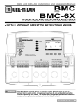
&211(&7,1*727+(%&3;3$1(/6$1'02',17(5)$&(
KH%&3:LVHTXLSSHGZLWKDSKRQHVRFNHW56WRFRQQHFWWRWKH%&3;([WHQVLRQSDQHOVRUWKH02',QWHUIDFH
7
XVLQJWKHSURYLGHGSLQSKRQHFDEOH
(DFK%&3;([WHQVLRQKDVWZR56FRPPXQLFDWLRQSRUWV8VHRQHWRFRQQHFWWRWKH%&3:8VHWKHRWKHUSRUWWR
connect to the second extension or the 420MOD Interface.
$GGLWLRQDOFRPSDWLEOHGHYLFHVFDQXWLOL]HWKHVHFRQG56FRQQHFWLRQRQWKHVHFRQG%&3;([WHQVLRQ$QH[DPSOHZRXOG
EHWRXVHWKH02',QWHUIDFHWRSURYLGHDP$VHWSRLQWVLJQDOWRWKH%&3:
6(/(&7,1*7+(%&3;3$1(//(77(5
KH%&3:LVFDSDEOHRIFRPPXQLFDWLQJWRWZR%&3;([WHQVLRQV+RZHYHUHDFK
7
H[WHQVLRQPXVWEHLGHQWL¿HGDVHLWKHU$RU%XVLQJWKHVZLWFKRQHDFKH[WHQVLRQWRDYRLGKDYLQJ
communication problem.
([WHQVLRQ$6ZLWFKLVVHWWR$ZLOORSHUDWHVWDJHV,WKURXJK3:KLOH([WHQVLRQ%
(Switch is set to "B") will operate stages "Q" through "X".
Ext A
Ext B
Connecting BCP-8 to Two Extension Panels
and 420MOD Interface using RS485
BCP-8
BCP-8X A
BCP-8W
BCP-8X
HYDRONIC SEQUENCING CONTROL
SYS=144F
Stage A
Stage E
SYSTEM
Stage B
Stage F
DHW PUMP
Stage C
Stage G
Stage D
Stage H
COMB. AIR
ENCLOSED
ENERGY
MANAGEMENT
EQUIPMENT
INPUT RATINGS:
115VAC 60Hz, 12VA MAX
LISTED
99RA
C
<AB > DE
HI
LO
GH
--
STAGE
JK
OFF
L T
O W
J R
MU
P X
K S
N V
MENU
OUTPUT RATINGS:
120VAC, 6A RESISTIVE
1A PILOT DUTY, 15A TOTAL
FOR ALL CIRCUITS
INPUT RATINGS:
115VAC 60Hz, 12VA MAX
Comm
DO NOT APPLY ANY VOLTAGE TO INPUT TERMINALS
SENSORS MUST BE GOLD SERIES
PROGRAM
I Q
Power
US
CAUTION: Risk of Electric Shock.
Use Copper Conductors Only.
SEQUENCING CONTROL EXTENSION
OD=35F
CAUTION: Risk of Electric Shock.
Use Copper Conductors Only.
RUN
PWR
SHUTDOWN
/TSTAT PROVE
/SETBACK
L N
Stage A Stage B Stage C Stage D Stage E Stage F
DHW COMB.
Stage G Stage H SYSTEM PUMP
AIR
PRESS
+
-
1 2
3 4 5 6 7 8 9 10 11 12 13 14
15 16 17 18 19 20 21 22 23 24
25 26 27 28 29 30 31 32 33 34 35 36 37 38
TEMP
OUTDOOR RETURN
TEMP
TEMP
DHW
PWR
RS485
Ext A
Ext B
EXTENSION
MODULE
I Q J R K S L T MU N V O W P X
L N
1 2
RS-485
3 4 5 6 7 8 9 10 11 12 13 14 15 16 17 18
6 Pin Phone Cable (provided with Extension)
BCP-8X B
BCP-8X
SEQUENCING CONTROL EXTENSION
420MOD EMS Interface
I Q
L T
O W
J R
MU
P X
K S
OUTPUT RATINGS:
120VAC, 6A RESISTIVE
1A PILOT DUTY, 15A TOTAL
FOR ALL CIRCUITS
INPUT RATINGS:
N V
Comm
115VAC 60Hz, 12VA MAX
Power
4-20 mA EMS
4-20mA INPUT
+
1
Signal GND
2
3
CAUTION: Risk of Electric Shock.
RS485
EXTENSION
CONNECTORS
Use Copper Conductors Only.
PWR
Ext A
Ext B
I Q J R K S L T MU N V O W P X
L N
1 2
4-20mA (+)
EMS Signal (-)
EXTENSION
MODULE
RS-485
3 4 5 6 7 8 9 10 11 12 13 14 15 16 17 18
6 Pin Phone Cable (provided with 420MOD EMS Interface)
13
%&3:,QVWDOODWLRQDQG2SHUDWLRQ0DQXDO
S
,167$//(5 0(18 6(48(1&(
67$5783
SYS=168 F OD=45 F
TGT=172 F
ABC
<EFG >
---LO
BOILER
MENU
------ SETTINGS -----Season
Winter
<Outdoor Rst> 135 F
Set Point
135 F
EMS Set Point135 F
Min Return
110 F
<System Settings>
<Maintenance>
<System Startup>
BACK
SELECT
0$,17(1$1&(
&
YOU
SURE?
SAVE
--- SENSOR FAULT --Stages On
Stages Off
BACK
SAVE
--- CONTROL
PID
OSS
BACK
LOGIC---
------ STAGING -----Multiple Outputs
Single Output
BACK
SAVE
Sys=120 F
BACK
SELECT
10:00AM
NEXT
--- SENSOR TRIM ---System Trim
+0 F
Outdoor Trim
+0 F
Return Trim
+0 F
DHW Trim
+0 F
BACK
SELECT
--
TOTAL
-------
---
SAVE
EMS
[
BACK
4mA SET POINT
100 F
]
SAVE
[
BACK
20mA SET
170 F
POINT
]
SAVE
SAVE
BOILERS
8
--
-- BOILER
None
Pump
Valve
BACK
OUTPUT
--
--- BURNER
On/Off
2-Stage
3-Stage
4-Stage
BACK
TYPE
[
BACK
UNIT
(06 6(7 32,17
EMS
BACK
BACK
---- DISPLAY
F
C
BACK
SAVE
------ SEQUENCE
Lo/Hi/Lo/Hi
Lo/Lo/Hi/Hi
BACK
SELECT
---- CONTROL MODE --Outdoor Reset
Set Point
EMS 4-20mA
BACK
SAVE
$/(57
7RDFFHVV,QVWDOOHU0HQXKROG
down the Menu button for over
three seconds.
7REHDEOHWRFKDQJHWKH%&3:
settings the Program/Run Switch
must be set to Program.
---- MAINTENANCE ---Unit
F
Present Time12:30P
<Sensor Trim>
<Histories>
<Configuration>
BCP-8W V1.00
Outdoor reset
Day/Night Schedule
DHW Parallel
14
ARE
No
Yes
BACK
]
SAVE
SAVE
----
SAVE
---- DHW PIPING --Parallel
Primary/Secondary
BACK
SAVE
--DHW PUMP
No
Yes
BACK
--COMB.
No
Yes
BACK
AIR
-- EXTERNAL
Shutdown
Tstat
Setback
BACK
OUTPUT-SAVE
OUTPUT-SAVE
INPUT
-
SAVE
%&3:,QVWDOODWLRQDQG2SHUDWLRQ0DQXDO
S
5(6(7
6
5$7,2
2
6(7 32,17
2
--
EMS
SET POINT
140 F
BACK
----[
BACK
--
SAVE
SET POINT
140 F
----]
SAVE
SYS=168 F OD=45 F
TGT=172 F
ABC
<EFG >
---LO
BOILER
MENU
---- SEASON
Winter
Summer
BACK
BACK
----
[
BACK
MIN
[
BACK
----
[
BACK
[
BACK
----
RETURN LAG
2min
[
BACK
-
---]
SAVE
SYSTEM SETTINGS <Stage Settings>
<Setback Schedule>
<DHW Settings>
Setback
0 F
Run-On
2min
Pump Exercise Off
BACK
--- PUMP
Off
On
BACK
SELECT
EXERCISE
--
--
TARGET
140 F
---]
SAVE
---]
SAVE
TARGET OFFSET
+0 F
---
]
SAVE
'+: 6(77,1*
*6
BACK
-----[
BACK
-------
BACK
SELECT
SETBACK
0 F
RUN-ON
2min
---- RESET RATIO --Custom
1(8.00 OD:1.00 SYS)
2(4.00 OD:1.00 SYS)
3(3.00 OD:1.00 SYS)
4(2.00 OD:1.00 SYS)
5(1.50 OD:1.00 SYS)
6(1.25 OD:1.00 SYS)
7(1.00 OD:1.00 SYS)
8(1.00 OD:1.25 SYS)
9(1.00 OD:1.50 SYS)
10(1.00 OD:2.00 SYS)
11(1.00 OD:3.00 SYS)
12(1.00 OD:4.00 SYS)
BACK
--
SET
[
]BACK
--
AT
[
]BACK
--
[
BACK
--
[
BACK
--
-
SAVE
OD TEMP.1
70 F
---
SYS TEMP.2
170 F
-
OD TEMP.2
0 F
---
]
SAVE
PRIORITY
2min
DHW
[
BACK
SYS TEMP.1
100 F
]
SAVE
AT
[
BACK
SAVE
SAVE
SET
DHW
-- DHW SETTINGS --DHW Temp.
120 F
DHW Prior Tmr 60min
DHW Set Point120 F
DHW Diff.
5 F
[
SAVE
TARGET
200 F
-- OUTDOOR CUTOFF -60 F
[
]
BACK
SAVE
---]
SAVE
SELECT
MAX
----- SETTINGS -----Season
Winter
<Outdoor Rst> 135 F
Set Point
135 F
EMS Set Point135 F
Min Return
110 F
<System Settings>
<Maintenance>
<System Startup>
BACK
SELECT
RETURN
120 F
SAVE
-- OUTDOOR RESET Reset Ratio
7
Target Offset +0 F
Outdoor Cutoff 65 F
Min.Target
120 F
Max.Target
120 F
----
MIN
---
TIMER
]
SAVE
SET POINT
140 F
--
]
SAVE
------]
SAVE
-------
DHW
[
]BACK
DIFFERENTIAL
10 F
SAVE
]
SAVE
15
%&3:,QVWDOODWLRQDQG2SHUDWLRQ0DQXDO
S
67$*
*( 6(77,1*
*6
-
SYSTEM SETTINGS <Stage Settings>
<Setback Schedule>
<DHW Settings>
Setback
0 F
Run-On
2min
Pump Exercise Off
BACK
SELECT
----- SETTINGS -----Season
Winter
<Outdoor Rst> 135 F
Set Point
135 F
EMS Set Point 135 F
Min Return
110 F
<System Settings>
<Maintenance>
<System Startup>
BACK
SELECT
--
STAGE SETTINGS -Reaction Time 1min
Purge Delay 0.0min
Min Runtime
2min
Standby Delay 10min
Last Stage Hold 5 F
Throttle
2 F
<Lead Settings>
BACK
SELECT
SETBACK SCHEDULE
Setback
0 F
Present Time **:**
Day Schdul 7:00Am
Night Schdul 7:00Pm
BACK
SELECT
--
-- LEAD ROTATION
Time
Manual
FOFO
--
SCHEDULE
07:**Am
BACK
-
SET
SELECT
BACK
-----[
BACK
16
TIME
SAVE
SETBACK
0 F
---]
SAVE
MINIMUM RUNTIME
2min
SAVE
STANDBY DELAY
10min
[
]BACK
LAST
-
--
SAVE
STAGE
0 F
HOLD
ROTATE PERIOD
24hrs
[
]
BACK
SAVE
[
BACK
-- LEAD
AB
CD
BACK
-- THROTTLE RANGE -2 F
[
]
BACK
SAVE
BOILER
--
SELECT
SYS=168 F OD=45 F
TGT=172 F
ABC
<EFG >
---LO
BOILER
MENU
]
SAVE
67$*
*( 0(18
-- BOILER
Auto
Standby
Off
On
BACK
AB
MODE
-
SAVE
---SAVE
PRESENT
**:**
[
BACK
--
--
SAVE
PURGE DELAY
1.0min
[
]BACK
SELECT
SAVE
DAY
---
BACK
-- NIGHT SCHEDULE -07:**Pm
BACK
[
]BACK
-
AUTO
6&
6&+('8/(6
6
REACTION TIME
1min
-- LEAD SETTINGS -Lead Boiler
AB
Rotate Mode
Time
BACK
1RW $YDLODEOH ZKHQ 6HWEDFN LV
6HOHFWHG IURP 6WDUWXS
S 0HQX
--
------]
SAVE
-----[
]BACK
-------[
BACK
BOOST PERIOD--30min
SAVE
BOOST
0 F
--------]
SAVE
----- BOILER AB ----Mode
Auto
Runtime
58Hrs
<Prev Boiler>
<Next Boiler>
BACK
SAVE
BOILER
BACK
AB RUNTIME
58hrs
CLEAR
OK
%&3:,QVWDOODWLRQDQG2SHUDWLRQ0DQXDO
67$57836(77,1*6
Can be accessed by holding down the Menu
button for over three seconds.
$/(57
$JRRGSUDFWLFHDIWHUSHUIRUPLQJDQ\6WDUWXSPHQXPRGL¿FDWLRQVLVWR
check all operating settings and adjustments to match the new settings.
352*5$0&+$1*(6(77,1*6
PROGRAM
To be able to change the BCP-8W settings the Program/Run Switch must be set to Program.
The switch is located under the Enclosure Wiring Cover for security. The Enclosure Wiring
Cover can be securely closed using a padlock.
RUN
67$57836(48(1&(
ARE YOU SURE?
Hold Button: MENU/<System Startup>
No
:KHQSRZHUHGWKH%&3:SHUIRUPVDVHOIWHVWRQLWVFRPSRQHQWV$IWHUWKHVHOIWHVW
Yes
GLDJQRVWLFVKDYHEHHQVXFFHVVIXOO\FRPSOHWHGWKH%&3:ZLOOLQLWLDOL]HWKHSDQHO
BACK
SAVE
2QWKH¿UVWSRZHUXSWKH6\VWHP6WDUWXSVFUHHQZLOODSSHDUDIWHUWKHLQLWLDOL]DWLRQLV
FRPSOHWH,ILWGRHVQ¶WWKH%&3:KDVDOUHDG\EHHQFRQ¿JXUHG
7KH6\VWHP6WDUWXSPHQXVHWVWKHPDLQSDUDPHWHUVDVWKHW\SHRIVHQVRUWKHVHTXHQFLQJPRGHDQGPDQ\RWKHUSDUDPHWHUV
described in this section.
%HIRUHHQWHULQJWKH6WDUWXSPHQXVHYHUDOZDUQLQJVZLOODOHUW\RXWRWKHFRQVHTXHQFHVRIPDNLQJ6WDUWXSFKDQJHV
&21752/02'(
---- CONTROL MODE --2XWGRRU5HVHW6HW3RLQW(06P$
'HIDXOW2XWGRRU5HVHW
Outdoor Reset
Hold Button: MENU/<System Startup>/..../Control Mode
Set Point
EMS 4-20mA
2XWGRRU5HVHWSURYLGHVDYDULDEOHVHWSRLQWEDVHGRQRXWGRRUWHPSHUDWXUH
2XWGRRU5HVHWPRGHUHTXLUHVWKHXVHRIDQRXWGRRUVHQVRU'2127VHOHFW2XWGRRU
BACK
SAVE
Reset without an outdoor sensor.
6HW3RLQWPRGHGRHVQRWUHTXLUHDQRXWGRRUVHQVRU,IDQRXWGRRUVHQVRULVFRQQHFWHGLQ6HW3RLQWPRGHLWZLOOEHXVHGRQO\DV
an Outdoor Cutoff point. That is, to turn the stages, system, and Comb. Air relays off.
7KH(06P$DOORZVWKH%&3:WRUHFHLYHDQH[WHUQDOVHWSRLQWIURPDQ(06%06V\VWHP7KLVRSWLRQUHTXLUHVWKHXVH
RIWKH02',QWHUIDFH
<RXPXVWVHOHFWWKHP$PLQDQGP$PD[6HW3RLQWYDOXHVLQWKHIROORZLQJVFUHHQV
&RQQHFWWKH02',QWHUIDFHWRWKH%&3:56FRQQHFWLRQXVLQJWKHSKRQHFDEOHSURYLGHGZLWKWKH02'LQWHUIDFH
',63/$<81,7
º)º&
'HIDXOWºF
Hold Button: MENU/<System Startup>/..../Display Unit
7KH%&3:FDQFRQWUROERLOHUVLQK\GURQLFHQYLURQPHQWZKHUHWKHWHPSHUDWXUHLV
the critical factor. It allows the user to display temperature information and settings in
either ºF (Fahrenheit) or ºC (Celsius). Select the display unit that is best suited for your
application.
---- DISPLAY
F
C
BACK
UNIT
---
SAVE
6(77,1*7+(0$$1'0$6(732,176$9$,/$%/(,10$(0621/<
P$IURP)&WR)&
'HIDXOW)&
P$IURP)&WR)&
'HIDXOW)&
Hold Button: MENU/<System Startup>/..../EMS 4mA Set Point/EMS 20mA Set Point
,I(06P$LVVHOHFWHGIURPWKH&RQWURO0RGHPHQXDVWKHWHPSHUDWXUHVHWSRLQW
VRXUFHWKHXVHUPXVWSXUFKDVHD:HLO0F/DLQ02',QWHUIDFHWR
accept the 4-20mA signal and transmit it to the BCP-8W.
,QDGGLWLRQWKHXVHUZLOOQHHGWRVHWWKHWHPSHUDWXUHUDQJHSDUDPHWHUV)LUVWVHWWKHP$
temperature set point, then the 20mA temperature set point.
7RVKXWGRZQWKHFRQWUROXVLQJWKH(06VLJQDOVHQGDVLJQDOWKDWLVDERYHRUEHORZWKH
2-22mA range. The display will show the message "Shutdown by EMS" and all
VWDJHVZLOOGHHQHUJL]H+RZHYHUWKH6\VWHP&RPE$LUDQGERLOHU3XPSVDQG9DOYHV
ZLOOFRQWLQXHIRUWKH5XQ2QGHOD\SHULRGDQGWKHQGHHQHUJL]H
EMS
[
BACK
EMS
[
BACK
4mA SET POINT
100 F
]
SAVE
20mA SET
170 F
POINT
]
SAVE
17
%&3:,QVWDOODWLRQDQG2SHUDWLRQ0DQXDO
'+:3,3,1*
---- DHW PIPING --3DUDOOHO3ULPDU\6HFRQGDU\
'HIDXOW3DUDOOHO
Parallel
Hold Button: MENU/<System Startup>/..../DHW Piping
Primary/Secondary
:KHQ3DUDOOHOLVVHOHFWHGWKH%&3:ZLOORIIHUD'+:3ULRULW\7LPHU7KH'+:
BACK
SAVE
priority will only take place during heating periods. See the DHW Priority Timer on
page 28.
7KHSULRULW\ZLOODOORZWKH'+:3XPSUHOD\WRHQHUJL]HZKLOHGHHQHUJL]LQJWKH6\VWHPUHOD\ZKHQWKHUHLVD'+:FDOOGXULQJ
KHDWLQJ+RZHYHUGXULQJ6XPPHURQO\WKH'+:3XPSUHOD\ZLOOHQHUJL]HRQD'+:FDOO
6HOHFWLQJWKH3ULPDU\6HFRQGDU\RSWLRQZLOOHQHUJL]HWKH6\VWHPUHOD\ZLWKWKH'+:3XPSUHOD\ZKHQHYHUWKHUHLVDFDOOIRU
DHW even during the Summer or when outdoor temperature is above the Outdoor Cutoff. No priority will be available.
$/(57
A DHW call can be initiated by either a dry contact or using a Weil McLain Sensor (389-900-230)
for immersion in a 3/8ID well (592-300-023). The use of a sensor will allow the adjustment of the
DHW Set Point and DHW Differential.
'+:3803287387
1R<HV
'HIDXOW<HV
Hold Button: MENU/<System Startup>/..../DHW Pump Output
7KH%&3:FDQFRQWUROWKHRSHUDWLRQRIWKH'+:3XPS7KLVRSWLRQDOORZVWKHXVHU
to select if the BCP-8W should be controlling the DHW Pump or not.
--DHW PUMP
No
Yes
BACK
OUTPUT-SAVE
&20%867,21$,5'$03(5287387
- COMB. AIR OUTPUT1R<HV
'HIDXOW<HV
No
Hold Button: MENU/<System Startup>/..../Comb. Air Output
Yes
7KH%&3:FDQFRQWUROWKHRSHUDWLRQRIWKH&RPEXVWLRQ$LU'DPSHU7KLVRSWLRQ
BACK
SAVE
allows the user to select if the BCP-8W should be controlling the Combustion Air
Damper or not.
,I<HVLVVHOHFWHGWKH%&3:ZLOOHQHUJL]HWKH&RPE$LUUHOD\ZKHQHYHUWKHUHLVDFDOOIRUDERLOHUDQGZLOOXVHWKHPROVE
LQSXWWRFKHFNRQWKHVWDWXVRIWKH&RPEXVWLRQ$LU'DPSHU:KHQWKHODVWVWDJHLVGHHQHUJL]HGWKH&RPE$LUUHOD\ZLOO
UHPDLQHQHUJL]HGIRUWKH5XQ2QSHULRGDQGWKHQGHHQHUJL]H
On a prove failure situation, the message "Wait for Comb. Prove". No boiler stages will be active until the Prove
input is Shorted.
,I3URYHIDLOVDIWHUWKHERLOHUVWDJHVZKHUHHQHUJL]HGWKHVWDJHVZLOOGHHQHUJL]HDQGWKHPHVVDJHComb. Prove
FailureZLOOGLVSOD\XQWLOWKHVLWXDWLRQLVUHFWL¿HG
,I1RLVVHOHFWHGWKHPROVE input will be used to check System status instead of the Combustion Air Damper.
(;7(51$/,138702'(
-- EXTERNAL INPUT 6KXWGRZQ7VWDW6HWEDFN
'HIDXOW7VWDW
Shutdown
Hold Button: MENU/<System Startup>/..../External Input
Tstat
Setback
7KH6KXWGRZQIXQFWLRQDOORZVWKH%&3:WRUHFHLYHDUHPRWH6KXWGRZQVLJQDOWR
WHUPLQDOVDQGWRWXUQRIIDOOUHOD\VLQFOXGLQJDOOERLOHUVVWDJHV
BACK
SAVE
:KHQ6KXWGRZQLVVHOHFWHG'+:FDOOVZLOOEHLJQRUHGXQOHVVWKHFRQWUROLVRXWRI
Shutdown.
7KH7VWDWRSWLRQJLYHVWHUPLQDOV35 and 36 the capability of functioning as a heat-call. That is, when terminals 35 and 36 are
shorted, the BCP-8W will sequence the stages. However, when they are opened, all stages will turn off. Thus, do not remove
the factory installed jumper unless it was replaced with a Tstat signal.
6HWEDFNLVXVHGWRORZHUWKHVHWSRLQWZKHQOHVVORDGLVUHTXLUHGGXULQJQLJKWVDQGZHHNHQGV
)RUVHWEDFNRSHUDWLRQWKH%&3:FDQHLWKHUXWLOL]HLWVEXLOWLQQLJKWVFKHGXOHDYDLODEOHZKHQ6KXWGRZQRU7VWDWLVVHOHFWHGDV
the External Input, or an external dry contact signal to switch to setback by selecting Setback from this menu.
18
%&3:,QVWDOODWLRQDQG2SHUDWLRQ0DQXDO
%851(57<3(
2Q2II6WDJH6WDJH6WDJH
'HIDXOW2Q2II
Hold Button: MENU/<System Startup>/..../Burner Type
7KH%&3:FDQVHTXHQFHIURPDVLQJOHVWDJHDQGXSWRIRXUVWDJHVSHUERLOHU6HOHFW
the option based on your boiler number of stages.
--- BURNER
On/Off
2-Stage
3-Stage
4-Stage
BACK
TYPE
----
SAVE
%2,/(5287387
-- BOILER OUTPUT -1RQH3XPS9DOYH
'HIDXOW1RQH
None
Hold Button: MENU/<System Startup>/..../Boiler Output
Pump
Valve
:KHQ1RQHLVVHOHFWHGWKH%&3:ZLOOVHTXHQFHPXOWLSOHERLOHUVZLWKRXWDQ\
additional boiler pumps or valves.
BACK
SAVE
7KH3XPSRSWLRQDOORZVWKH%&3:WRFRQWUROWKHERLOHUVWDJHVLQDGGLWLRQWRWKHERLOHU
pumps. The pump stage will run for the Run-On delay after the lower stage of that boiler
KDVGHHQHUJL]HG
7KH9DOYHRSWLRQIXQFWLRQVVLPLODUWRWKHSXPSRSWLRQH[FHSWWKDWZKHQDOOVWDJHVDUHRIIDQGDIWHUWKH5XQ2QGHOD\KDV
HODSVHGWKH/HDGERLOHU
VYDOYHUHOD\ZLOOUHPDLQHQHUJL]HGWRDOORZIRUÀRZDFURVVWKHV\VWHP7KHOHDGERLOHU
VYDOYHZLOO
UHPDLQHQHUJL]HGXQWLOWKHRXWGRRUWHPSHUDWXUHULVHVDERYHWKH2XWGRRU&XWRIIRUZKHQWKH6KXWGRZQRU6XPPHULVDFWLYDWHG
727$/%2,/(56
IURPWR
'HIDXOWYDULHVEDVHGRQ%XUQHU7\SHDQG%RLOHU2XWSXW
Hold Button: MENU/<System Startup>/..../Boiler Output
7KLVRSWLRQLQFRPELQDWLRQZLWK%XUQHU7\SHDQG%RLOHU2XWSXW6WDUWXSRSWLRQVZLOO
determine the total number of outputs the BCP-8W will need to control.
,IWKHWRWDOQXPEHURIVWDJHVVHOHFWHGLQFOXGLQJERLOHUSXPSVRUYDOYHVLVPRUHWKDQWKH
control and extension stages, the additional boilers containing these stages will have CE
DVWKHLUVWDWXVDQGZLOOVHL]HWRRSHUDWH
67$*,1*
0XOWLSOH2XWSXWV6LQJOH2XWSXW
'HIDXOW0XOWLSOH2XWSXWV
Hold Button: MENU/<System Startup>/..../Staging
0RVWERLOHUVZLOOUHTXLUHWKDWWKHKLJKHURXWSXWVWDJHVEHHQHUJL]HGDIWHUWKHORZHURXWSXW
stages. These boilers will need to select the Multiple Output option. That means, both
/RZDQG+LJK2XWSXWVWDJHVPXVWEHHQHUJL]HGWRDFKLHYHWKHERLOHU
VPD[LPXPRXWSXW
6RPHHTXLSPHQWUHTXLUHWKDWZKHQWKHKLJKHURXWSXWVWDJHVDUHUHTXLUHGWKHORZHUVWDJHV
PXVWGHHQHUJL]H7RRSHUDWHWKHVHHTXLSPHQWWKHXVHUPXVWVHOHFWWKH6LQJOH2XWSXW
option.
--
TOTAL
[
BACK
BOILERS
8
--
]
SAVE
------ STAGING -----Multiple Outputs
Single Output
BACK
SAVE
6(48(1&(
------ SEQUENCE ------/R+L/R+L/R/R+L+L
'HIDXOW/R+L/R+L
Lo/Hi/Lo/Hi
Hold Button: MENU/<System Startup>/..../Sequencing
Lo/Lo/Hi/Hi
6RPHERLOHUVUXQPRUHHI¿FLHQWZKHQWKHORZHUVWDJHVDUHHQHUJL]HGDORQHWKDQZLWKWKH
BACK
SAVE
KLJKHUVWDJHV7KHVHW\SHVRIERLOHUVVKRXOGVHOHFW/R/R+L+L7KHQWKH%&3:ZLOO
sequence the lower stages of all Automatic boilers before sequencing the higher stages.
)RUWKHUHVWRIWKHERLOHUW\SHVWKH/R+L/R+LVKRXOGDOORZWKHVWDJLQJRIWKHORZHUVWDJHRIWKHOHDGERLOHUIROORZHGE\WKH
KLJKHUVWDJHRIWKHVDPHERLOHU7KHQZKHQPRUHVWDJHVDUHQHHGHGLWZLOO¿UHWKHORZHUVWDJHRIWKHODJERLOHUIROORZHGE\WKH
higher stage of the lag boiler.
&21752//2*,&
3,'2662YHU6L]HG6\VWHP
'HIDXOW3,'
Hold Button: MENU/<System Startup>/..../Sequencing
7KH3,'RSWLRQDOORZVWKH%&3:WRVHTXHQFHVWDJHVEDVHGRQWKH5HDFWLRQ7LPH
and the Boiler Minimum Run Time. The PID relies on the rate of change in the System
Temperature. The PID logarithmic calculations foresee changes and sequence stages
EDVHGRQWKRVHFKDQJHV,WLVWKHPRVWHI¿FLHQWRSHUDWLRQIRUPRVWKHDWLQJDSSOLFDWLRQV
--- CONTROL
PID
OSS
BACK
LOGIC--SAVE
19
%&3:,QVWDOODWLRQDQG2SHUDWLRQ0DQXDO
KH2YHUVL]HRSWLRQVHTXHQFHVWDJHVEDVHGRQKRZPDQ\7KURWWOLQJUDQJHVGLIIHUHQWLDOVLVWKHV\VWHPWHPSHUDWXUHDZD\IURP
7
the Target Temperature. At one Throttling range below the Set Point, only one stage will be on. For each additional Throttling
range below the Set Point, an additional stage will be activated. The last stage on will be allowed to exceed the Set Point by one
Throttling range before turning off that stage. This helps to prevent the last stage from short cycling.
:KHQ3,'LV6HOHFWHGWKHIROORZLQJDUHWKHVHWWLQJVWKDWGLUHFWO\DIIHFWVWKLVPRGHVRSHUDWLRQ
5HDFWLRQ7LPHSJ24 6(/(&7Settings/System Settings/Stage Settings/Reaction Time
3XUJH'HOD\(pg 24) 6(/(&7Settings/System Settings/Stage Settings/Purge Delay
0LQLPXP5XQ7LPH(pg 24) 6(/(&7Settings/System Settings/Stage Settings/Min Runtime
6WDQGE\'HOD\(pg 25) 6(/(&7Settings/System Settings/Stage Settings/Standby Delay
/DVW6WDJH+ROG(pg 25) 6(/(&7Settings/System Settings/Stage Settings/Last Stage Hold
:KHQ2YHUVL]H266LV6HOHFWHGWKHIROORZLQJDUHWKHVHWWLQJVWKDWGLUHFWO\DIIHFWVWKLVPRGHVRSHUDWLRQ
7KURWWOH(pg 25) 6(/(&7Settings/System Settings/Stage Settings/Throttle
6(1625)$8/7
--- SENSOR FAULT --6WDJHV2Q6WDJHV2II
'HIDXOW6WDJHV2Q
Stages On
Hold Button: MENU/<System Startup>/..../Sensor Fault
Stages Off
The Sensor Fault will determine the operating status of all output stages set to Auto or
BACK
SAVE
Standby when a sensor reads Short or Open.
7KH6KXWGRZQRU7VWDWDFWLYDWLRQZLOOWDNHSUHFHGHQFHRYHUWKH6HQVRU)DXOWVWDWXV7KDWPHDQVLI6WDJHV2QLVVHOHFWHGDQG
the Shutdown was active, all stages will be Off on a sensor fault.
5(6(702'(
:KHQ6WDJHV2QLVVHOHFWHGWKH%&3:ZLOOWXUQDOOERLOHUVWDJHV2QZKHQWKH6\VWHPUHDGVShort or Open and the
outdoor is below the Outdoor Cutoff. When the Outdoor reads Short or Open, the BCP-8W will change the Target to the
Maximum Target.
:KHQ6WDJHV2IILVVHOHFWHGWKH%&3:ZLOOWXUQDOOVWDJHV2IIZKHQWKH6\VWHPUHDGVShort or Open. However, when
the Outdoor reads Short or Open, the BCP-8W will change the Target to the Minimum Target.
6(732,1702'(
:KHQ6WDJHV2QLVVHOHFWHGWKH%&3:ZLOOWXUQDOOVWDJHV2QZKHQWKH6\VWHPVHQVRUUHDGVShort or Open.
:KHQ6WDJHV2IILVVHOHFWHGWKH%&3:ZLOOWXUQDOOVWDJHV2IIZKHQWKH6\VWHPVHQVRUUHDGV Short or Open.
7KH2XWGRRU6HQVRU6KRUWRU2SHQVWDWXVZLOOQRWDIIHFWWKHFRQWURORSHUDWLRQLQ6HW3RLQWPRGH
6(77,1*7+(&21752/72)$&725<'()$8/76
To Reset the BCP-8W control to its original factory defaults, power down the control. Hold
down the two right most buttons while powering the control back up until the Total
Clear Started screen appears. The Display will direct you to the Startup menu to
program the control after the defaults are loaded.
TOTAL CLEAR STARTED
Release buttons
and
Please Wait
127(:KHQUHVHWWLQJWKHFRQWUROWRRULJLQDOIDFWRU\GHIDXOWVDOOFRQWUROVHWWLQJVZLOOEHRYHUZULWWHQDQGZLOOQRORQJHUH[LVW
$/(57
Do not turn off power to control until all Startup settings have been made. Otherwise, the next
SRZHUXSZLOOEHVHWWRPDQ\6WDUWXSIDFWRU\VHWWLQJVWKDWPLJKWQRW¿W\RXUDSSOLFDWLRQ
23(5$7,1*6(77,1*6
352*5$0&+$1*(6(77,1*6
To be able to change the BCP-8W settings the Program/Run Switch must be set to Program.
The switch is located under the Enclosure Wiring Cover for security. The Enclosure Wiring
Cover can be securely closed using a padlock.
20
PROGRAM
RUN
%&3:,QVWDOODWLRQDQG2SHUDWLRQ0DQXDO
6($621
5(6(75$7,2
&XVWRP2'6\VWR2'6\V'HIDXOW2'6\V
Hold Button: MENU/<Outdoor Reset>/Reset Ratio
,Q2XWGRRU5HVHW2QO\
7KH5HVHW5DWLRGHWHUPLQHVKRZWKHV\VWHP7DUJHWWHPSHUDWXUHZLOOYDU\EDVHGRQWKH
outdoor temperature. With any of the ratios, the colder it becomes outside, the hotter the
temperature of the system water. (See Understanding Operation Concept on page 5)
:LWKD2'6<6UDWLRWKH6\VWHPZDWHUWHPSHUDWXUH6<6ZLOOLQFUHDVH
UDSLGO\DVWKHRXWVLGHWHPSHUDWXUHIDOOVKLWWLQJWKH0D[LPXPRI)DW)RXWVLGH
WHPSHUDWXUH:LWKD2'6<6UDWLRWKH6\VWHPWHPSHUDWXUH6<6ZLOO
LQFUHDVHVORZO\DVWKHRXWVLGHWHPSHUDWXUHIDOOV(YHQDW)WKHV\VWHPZDWHUZLOO
only be 125°F, and at 22°F outside, the system water will be 112°F. Such a low Reset
5DWLRPLJKWEHXVHGZLWKUDGLDQWÀRRUKHDWLQJDSSOLFDWLRQV
:LWKPRVWEDVHERDUGKHDWLQJDSSOLFDWLRQVD2'6<6) setting is a good
SODFHWRVWDUW:LWKD2'6<6) ratio, for every degree the outside
temperature falls, the system water temperature is increased one degree.
,IUHTXLUHG$GMXVWWKH5(6(75$7,2LQFROGZHDWKHU If the ambient building
temperature are cold in cold weather, move the ratio to a higher selection. That is, if
2'6<6ZDVLQLWLDOO\VHOHFWHGFKDQJHWKHVHOHFWLRQWR2'
(6<6). If the building temperature are too warm in cold weather, move the ratio to a
ORZHUVHOHFWLRQ7KDWLVLI2'6<6) was initially selected, change it to 1.25
2'6<6).
$IWHUVHOHFWLQJWKH5HVHW5DWLRSUHVVLQJWKHSAVE button will switch to the Outdoor
Cutoff setting option.
$/(57
DO NOT turn power off to the
BCP-8W when in off-season.
If you do so, the battery will
run down and have to be
replaced. Instead, switch
Season to Summer.
---- SEASON
Winter
Summer
BACK
--SAVE
---- RESET RATIO --Custom
1(8.00 OD:1.00 SYS)
2(4.00 OD:1.00 SYS)
3(3.00 OD:1.00 SYS)
4(2.00 OD:1.00 SYS)
5(1.50 OD:1.00 SYS)
6(1.25 OD:1.00 SYS)
7(1.00 OD:1.00 SYS)
8(1.00 OD:1.25 SYS)
9(1.00 OD:1.50 SYS)
10(1.00 OD:2.00 SYS)
11(1.00 OD:3.00 SYS)
12(1.00 OD:4.00 SYS)
BACK
SAVE
Water Temperature
:LQWHU6XPPHU
'HIDXOW:LQWHU
Button: MENU/Season
7KH%&3:ZLOOWXUQDOOERLOHUUHOD\VRIIZKHQLWLVLQ6XPPHUVHWWLQJThe Message
'LVSOD\/LQHZLOOUHDGSummer to show status. However, a DHW call will bring the
boilers back on if needed. When in Winter, the BCP-8W will activate the System relay
whenever the Outdoor temperature falls to or below the Outdoor Cutoff setting. In
addition, it will begin heating whenever the System temperature falls below the Set Point
7HPSHUDWXUH7KH0HVVDJH'LVSOD\/LQHZLOOQRWGLVSOD\DQ\VHDVRQLQIRUPDWLRQ
:KHQWKHVHDVRQLVRYHULWLVDJRRGSUDFWLFHWRVZLWFKWKH%&3:6HDVRQVHWWLQJ7KLV
will allow DHW calls to operate the boilers when needed.
130
1:4
1:1
Warmer
120
Colder
110
100
4:1
70
60
50
40
Outdoor Temperature
&86720,=('5(6(75$7,2
Hold Button: MENU/<Outdoor Reset>/Reset Ratio/Custom
)RUVLWXDWLRQVZKHUHWKHDYDLODEOHUHVHWUDWLRVGRQRWSURYLGHWKHSHUIHFWEXLOGLQJKHDWORVVHTXLOLEULXPWKHFXVWRPL]HGRSWLRQ
can be used by selecting Custom from the Reset Ratio menu option.
,WSURYLGHVWKHXVHUZLWKWKHFDSDELOLW\RIDVVLJQLQJWZRSRLQWVRQWKHUHVHWUDWLRGLDJUDPDQGXVHWKHOLQHWKDWFRQQHFWVWKRVH
WZRSRLQWVDVWKHFXVWRPL]HGUHVHWUDWLRFXUYH(DFKRIWKHWZRSRLQWVZLOOQHHGDVSHFL¿F6\VWHPDQG2XWGRRU7HPSHUDWXUHWR
identify it on the diagram.
7R6HWWKH¿UVWSRLQWVSHFLI\6\V7HPSDQG2'7HPS7KHQVSHFLI\6\V7HPSDQG2'7HPSWRVHWWKHVHFRQGSRLQW
on the curve. The two points can be anywhere on the line, not necessarily at the ends.
7KHFKDUWVKRZVDQH[DPSOHRIDFXVWRPL]HGFXUYH2'6<6WKDWGRHVQRWH[LVWLQWKHVWDQGDUGFXUYHRSWLRQV,IWKH
RXWGRRUWHPSHUDWXUHUHDFKHV)WKHV\VWHPWDUJHWZLOOEH)
5HPHPEHUWKDWWKH2IIVHW0LQ7DUJHWDQG0D[7DUJHWDSSO\WRDOOUHVHWUDWLRVLQFOXGLQJWKHFXVWRPL]HGUHVHWUDWLRRQHV
21
%&3:,QVWDOODWLRQDQG2SHUDWLRQ0DQXDO
--
SET
[
BACK
--
AT
[
BACK
SYS TEMP.1
120 F
-
]
SAVE
OD TEMP.1
60 F
---
]
SAVE
--
SET
[
BACK
--
AT
[
BACK
SYS TEMP.2
170 F
Water Temperature (in °F)
Point1: System=120°F
Oudoor=60°F
180
-
]
SAVE
OD TEMP.2
0 F
---
Point2: System=170°F
Oudoor=0°F
Max Target
tio
170
et
160
ed
Ra
Point2
s
Re
iz
om
st
150
Cu
140
130
Point1
120
Min Target
110
100
]
SAVE
70
60
50
40
30
20
10
0
-10 -20
Outdoor Temperature (in °F)
Custom Reset Ratio
6(732,17127$'-867$%/(,1(0602'(
----- SET POINT ----$GMXVWDEOHIURPº)º&WRº)ºC
'HIDXOWº)º&
70 F
Button: MENU/Set Point
,Q6HW3RLQWRU(06P$
[
]
7KH6HWSRLQWLVWKHWHPSHUDWXUHYDOXHWKH%&3:ZLOOXVHWRFRQWUROWKHV\VWHP
BACK
SAVE
7KH%&3:ZLOODGGVXEWUDFWRUKROGWKHVWDJHVRIWKHKHDWLQJERLOHUVWRPDLQWDLQWKH
system temperature around the Set point.
7KHV\VWHPFDQEHH[SHFWHGWRÀXFWXDWHDURXQGWKHVHWSRLQW7KHDPRXQWRIÀXFWXDWLRQGHSHQGVRQWKH6\VWHP6HWWLQJVDQG
Stage Settings.
,IDQ2XWGRRU6HQVRUZDVFRQQHFWHGSUHVVLQJWKHSAVE button will continue to the Outdoor Cutoff setting option.
,IWKH(060RGHZDV(QDEOHGWKH6HW3RLQWZLOOEHVHWE\WKH(06%06V\VWHPDQGZLOOEHDYDLODEOHDVDUHDGRQO\
7KHUDQJHRI6HW3RLQWLQWKH(06LVVHWLQWKH6WDUWXSPHQXDWP$DQGP$
$Q\UHDGLQJEHORZWKHP$RUDERYHP$ZLOOLQGLFDWHDShutdown by EMSPHVVDJHRQWKH0HVVDJH/LQH
287'225&872))7(03(5$785(
-- OUTDOOR CUTOFF -$GMXVWDEOH2IIIURPº)º&WRº)º&2Q
'HIDXOW)&
70 F
Hold Button: MENU/Set Point/Outdoor Cutoff
LQ6HW3RLQW
[
]
Hold Button: MENU/<Outdoor Reset>/Outdoor Cutoff
LQ5HVHW
BACK
SAVE
,Q2XWGRRU5HVHWPRGH2XWGRRU&XWRIIZLOODOZD\VH[LVW+RZHYHULQ6HW3RLQWPRGH
if the outdoor sensor is installed, the Outdoor Cutoff screen will automatically appear
after the temperature Set Point has been selected.
:KHQWKHRXWGRRUWHPSHUDWXUHIDOOVWRWKHDGMXVWDEOH2XWGRRU&XWRIIWHPSHUDWXUHWKH%&3:ZLOOFRQWURODQGVHTXHQFHWKH
boiler stages to hold the calculated temperature.
:KHQWKHRXWGRRUWHPSHUDWXUHULVHVWRWKH2XWGRRU&XWRIISOXVD)GLIIHUHQWLDOWKH%&3:ZLOOWXUQDOOERLOHUVRII7KH
6\VWHP&RPEXVWLRQ$LU'DPSHUDQGDQ\RWKHU3XPSRUYDOYHUHOD\VWKDWZHUHHQHUJL]HGZLOOUHPDLQHQHUJL]HGIRUWKH5XQ2Q
delayDQGWKHQGHHQHUJL]H.
,QDGGLWLRQWKH2XWGRRU&XWRIIFDQEHVHWWR21RU2)),QWKH21RSWLRQWKH6\VWHP5HOD\ZLOOUXQUHJDUGOHVVRIWKH2XWGRRU
temperature and the burner stages will be active to hold the target water temperature.
,QWKH2))SRVLWLRQWKHV\VWHPSXPSZLOODOZD\VEHRIIDQGDOOVWDJHVZLOOEHRIIDVZHOO
7$5*(72))6(7
$GMXVWDEOHIURPº)º&WRº)º&
'HIDXOWº)º&
Hold Button: MENU/<Outdoor Reset>/Offset
LQ2XWGRRU5HVHWRQO\
7KH2IIVHWVHWWLQJPRYHVWKH5HVHW5DWLRFXUYHYHUWLFDOO\7KLVPHDQVWKDWUHJDUGOHVV
of the Outdoor temperature, or the Reset Ratio that has been selected, when the Offset
setting is changed, that change is directly added to or subtracted from the calculated
WHPSHUDWXUH)RUH[DPSOHLIWKH6HW3RLQWWHPSHUDWXUHZDV)DQGWKH2IIVHWZDV
changed from 0° to 10° (an increase of 10°), the Set Point would increase to 140°F.
22
--
TARGET OFFSET
+0 F
[
BACK
---
]
SAVE
%&3:,QVWDOODWLRQDQG2SHUDWLRQ0DQXDO
KH2IIVHWVHWWLQJGRHVQRWFKDQJHWKHUDWLRVHOHFWLRQ)RULQVWDQFHZLWK2'
7
6<65HVHW5DWLRWKH6\VWHPZDWHUWHPSHUDWXUHZLOODOZD\VLQFUHDVHRQHGHJUHHIRU
every 1.5 degree change in the Outdoor temperature. What the Offset does is add or
subtract a constant temperature value. (See Understanding Operation Concept on page 5)
7KH0LQLPXPDQG0D[LPXP7DUJHWZLOOWDNHSUHFHGHQFHRYHUWKH2IIVHW7KDWLVLIWKH
0D[7DUJHWZDVVHWWR)DQGWKH2IIVHWZDVVHWWR),IWKHVHWSRLQWZDV)
the new calculated set point based with the Offset should be 175°F. However, it will not
exceed 170°F due to the Maximum Target setting.
,IUHTXLUHG$GMXVWWKH:DWHU2IIVHWLQPLOGZHDWKHU. If the ambient building
temperatures are too warm in the mild weather, decrease the Target Offset. If the
ambient building temperatures are too cold in the mild weather, increase the Target
Offset. The rule of thumb for baseboard radiation is to change the Offset 4°F for every
1°F you wish to change the building temperatures. In radiant heat applications, change
the Offset 1°F or 2°F for every 1°F you wish to change the building temperature.
Offset=10°F
Reset Ratio=1.5 : 1.0
Min Target=120°F
Max Target=170°F
180
Water Temperature (in °F)
170
Max Target
t
fse
160
0F
Of
1
o+
150
io
ati
at
tR
tR
se
140
se
Re
Re
130
Min Target
120
110
100
70
60
50
40
30
20
10
0
-10 -20
Outdoor Temperature (in °F)
Target Offset
0,1,0807$5*(7
---- MIN TARGET ---$GMXVWDEOHIURPº)º&WRº)º&
'HIDXOWº)º&
140 F
Hold Button: MENU/<Outdoor Reset>/Min. Target
LQ2XWGRRU5HVHWRQO\
[
]
7KH0LQLPXP7DUJHWPXVWEHVHWWRWKHERLOHUPDQXIDFWXUHU¶VVSHFL¿FDWLRQ7KH%&3
BACK
SAVE
8W will calculate the Set Point based on the Outdoor temperature, the Reset Ratio, and
the Offset value. The BCP-8W will control all boilers to hold either the Set Point
temperature, or the Minimum Target, whichever is higher.
7KH0LQLPXP7DUJHWPXVWEHDWOHDVW)ORZHUWKDQWKH0D[LPXP7DUJHW6HHQH[WVHWWLQJ
0$;,0807$5*(7
$GMXVWDEOHIURPº)º&WRº)º&
'HIDXOWº)º&
Hold Button: MENU/<Outdoor Reset>/Max. Target
LQ2XWGRRU5HVHWRQO\
7KLVLVWKHKLJKHVW7DUJHWWHPSHUDWXUHWKH%&3:ZLOOFDOFXODWHIRUWKHKHDWLQJV\VWHP
:KHQXVLQJLQÀRRUUDGLDQWV\VWHPLWVKRXOGEHVHWDFFRUGLQJWRWKHWXELQJRUÀRRU
PDQXIDFWXUHU¶VVSHFL¿FDWLRQ
7KH0D[LPXP7DUJHWPXVWEHDWOHDVW)KLJKHUWKDQWKH0LQLPXP7DUJHW6HH
previous setting)..
----
MAX
[
BACK
TARGET
200 F
---]
SAVE
%2,/(50,1,0805(7851
When a return sensor is connected to the BCP-8W, it will monitor and control the boiler return. It does that by monitoring the Target
WHPSHUDWXUH7*76\VWHPWHPSHUDWXUH6<60LQLPXP5HWXUQDQGDFWXDOUHWXUQ571:KHQWKH%&3:IRUHVHHVWKDWDORZ
return will occur, it will increase the Target automatically as an effort to increase the return temperature. See Return Sensor Wiring on
page 10.
0,1,0805(7851
---- MIN RETURN ---$GMXVWDEOH2IIIURPº)º&WRº)º&
'HIDXOW2II
OFF
Hold Button: MENU/Min. Return
[
]
7KH0LQLPXP5HWXUQLVWKHFULWLFDOWHPSHUDWXUHDWZKLFKWKHUHWXUQVKRXOGEHDERYH
BACK
SAVE
Normally, this setting is provided by the boiler manufacturer or the system engineer.
7KH%&3:ZLOOXVHWKDWYDOXHDVDJXLGH,WZLOOVWDUWWRDGGDGGLWLRQDOVWDJHVLILWIRUHVHHVWKDWWKH571WHPSHUDWXUHZLOO
drop below the Min. Return. During that period, it will display "Hold Return at 120 F" in the Display Message
/LQHWRLQGLFDWHWKDWWKH%&3:LVVHTXHQFLQJERLOHUVWRSURWHFWWKHUHWXUQIURPGURSSLQJEHORZWKH0LQLPXP5HWXUQ
0RVWFRQGHQVLQJERLOHUVZLOOUXQPRUHHI¿FLHQWZLWK&RROHUUHWXUQWHPSHUDWXUHV,QWKLVFDVHVHOHFWWKH2IIRSWLRQRQWKH
Minimum Return to allow the monitoring of the return on the display without sequencing the boiler stages.
23
%&3:,QVWDOODWLRQDQG2SHUDWLRQ0DQXDO
5(7851/$*
$GMXVWDEOHIURPWRPLQXWHV
'HIDXOWPLQXWHV
Hold Button: MENU/Min. Return/Return Lag
,WLVWKHWLPHLWWDNHVIRUWKHV\VWHPUHWXUQWRFKDQJHDIWHUVHTXHQFLQJWKHVWDJHV
,QLWLDOO\DGMXVWWKLVYDOXHWRHTXDOWKH5HDFWLRQ7LPH7KHQLQH[WUHPHFROGZHDWKHU
monitor the return making sure it is about 10°F above the Minimum Return setting and
adjust it if needed.
6<67(06(77,1*6
----
To be able to change the BCP-8W settings the Program/Run Switch must be set to Program.
The switch is located under the Enclosure Wiring Cover for security. The Enclosure Wiring
Cover can be securely closed using a padlock.
67$*(6(77,1*6
Button: MENU/<System Settings>/<Stage Settings>
5($&7,217,0(
$GMXVWDEOHIURPWRPLQXWHV
'HIDXOWPLQXWHV
Hold Button: MENU/<System Settings>/<Stage Settings>/Reaction TimeLQ3,'/RJLFRQO\
,WLVWKHDPRXQWRIWLPHLWWDNHVDVLQJOHVWDJHWRDIIHFWWKHV\VWHP
$IWHUWKH%&3:WXUQVRQDVWDJHWU\LQJWRPHHWDVHWSRLQWLWZLOOQRWWXUQRQDQRWKHU
stage until the Reaction Time has elapsed.
7RGHWHUPLQHWKHRSWLPXPWLPHLQDKHDWLQJV\VWHPVWDUWZLWKDKRWV\VWHP7XUQRQ
a single stage and calculate how long it takes until the system begins to respond to that
stage. That period should be set as the Reaction Time (See PID operation ).
----
[
BACK
-
Hold Button: MENU/<System Settings>
7KH6\VWHP6HWWLQJVPHQXSURYLGHVDFFHVVWRDGMXVWLQJDQG¿QHWXQLQJWKHV\VWHPIRUHQKDQFHG
comfort and better fuel savings. The BCP-8W behaves differently based on the selected Control
Modes (see Startup Settings 17).
352*5$0&+$1*(6(77,1*6
RETURN LAG
2min
]
SAVE
SYSTEM SETTINGS <Stage Settings>
<Setback Schedule>
<DHW Settings>
Setback
0 F
Run-On
2min
Pump Exercise Off
BACK
SELECT
PROGRAM
RUN
-- STAGE SETTINGS -Reaction Time 1min
Purge Delay 0.0min
Min Runtime
2min
Standby Delay 10min
Last Stage Hold5 F
Throttle
2 F
<Lead Settings>
BACK
--
SELECT
REACTION TIME
2min
[
BACK
--
]
SAVE
385*('(/$<
--- PURGE DELAY ---$GMXVWDEOHIURPWRPLQXWHV
'HIDXOWPLQXWHV
1.0min
Hold Button: MENU/<System Settings>/<Stage Settings>/Purge DelayLQ3,'/RJLFRQO\
[
]
0RVWODUJHERLOHUVPXVWJRWKURXJKDSXUJHF\FOHEHIRUHWKH\DUHEURXJKWRQOLQH
BACK
SAVE
:KHQWKH%&3:DFWLYDWHVDERLOHUWKHORZHVWVWDJHRQDERLOHULWGRHVQRWVWDUWWR
calculate its output until the Purge Delay is over. This allows the boiler to fully come on
line and to begin producing output.
7KH3XUJH'HOD\KHOSVSUHYHQWVKRUWF\FOLQJRIDQHZO\DFWLYDWHGERLOHU2QFHWKHORZHVWERLOHUVWDJHLVDFWLYDWHGLW0867UXQ
through the entire Purge Delay period (See PID operation on page ).
7KHPLQLPXP3XUJH'HOD\VHWWLQJ0867EHVHWWRWKHWLPHUHTXLUHGE\WKHERLOHUVPDQXIDFWXUHUVSHFL¿FDWLRQ
0,1,0805817,0(
- MINIMUM RUNTIME $GMXVWDEOHIURPWRPLQXWHV
'HIDXOWPLQXWHV
1min
Hold Button: MENU/<System Settings>/<Stage Settings>/Min RuntimeLQ3,'/RJLFRQO\
[
]
7KLVLVWKHPLQLPXPDPRXQWRIWLPHDQ\VWDJHZLOOUXQ (See PID operation on page ).
BACK
SAVE
)RUWKHORZHVWVWDJHRIDERLOHUWKH0LQLPXP5XQWLPHVWDUWVDIWHUWKHSXUJHF\FOH
7KLVWLPHUGRHVQRWDSSO\WRWKHODVWVWDJHRQOLQH7KH/DVW6WDJH+ROGDSSOLHVLQWKDWFDVH
,QLWLDOO\VHWWKHMinimum Runtime to half the Reaction Time.
,I6\VWHPWHQGVWRRYHUVKRRWUHGXFHWKHMinimum Runtime. If boilers tend to short cycle, increase Minimum Runtime.
24
%&3:,QVWDOODWLRQDQG2SHUDWLRQ0DQXDO
67$1'%<'(/$<
-- STANDBY DELAY -$GMXVWDEOHIURPWRPLQXWHV
'HIDXOWPLQXWHV
10min
Hold Button: MENU/<System Settings>/<Stage Settings>/Standby DelayLQ3,'/RJLFRQO\
[
]
7KH6WDQGE\'HOD\RQO\DSSOLHVWRERLOHUVLQ6WDQGE\0RGH6HH0RGHRQSDJH2.
BACK
SAVE
$6WDQGE\ERLOHUFDQRQO\EHDFWLYDWHGDIWHUDOOWKHERLOHUVLQ$XWR0RGHKDYHKDGDOO
their stages on running for the full Standby Time.
6WDQGE\ERLOHUVDUHXVHGDVDEDFNXSLQH[WUHPHORDGFRQGLWLRQV$6WDQGE\ERLOHUFDQQHYHUEHD/HDGERLOHU
7KHIXOO6WDQGE\'HOD\PXVWDOZD\VHODSVHUHJDUGOHVVRIZKDWKDSSHQVWRWKHV\VWHPWHPSHUDWXUH7KHUHIRUHVKRUWHU6WDQGE\
WLPHVZLOOUHVXOWLQVPRRWKHUVHWSRLQWRSHUDWLRQLQH[WUHPHFRQGLWLRQV/RQJHU6WDQGE\WLPHVPD\SUHYHQWD6WDQGE\ERLOHU
from starting if the other boilers can eventually meet the load or if the load decreases.
:KHQVHWWLQJWKH6WDQGE\'HOD\UHPHPEHUWKDWLWZLOOEHDGGHGWRWKH5HDFWLRQ7LPHIRUWKH¿UVWVWDJHRQWKH¿UVWVWDQGE\
boiler. The following stages start time will rely on Pre-Purge and Reaction Time only.
/$6767$*(+2/'
LAST STAGE HOLD
$GMXVWDEOHIURP)º&ºWR)º&º
'HIDXOW)º&º
5 F
Hold Button: MENU/<System Settings>/<Stage Settings>/Lst Stg Hld LQ3,'/RJLFRQO\
[
]
7KH/DVW6WDJH+ROGSUHYHQWVVKRUWF\FOLQJRIWKH/HDG6WDJHGXULQJORZORDGFRQGLWLRQV
BACK
SAVE
ZKHUHWKHV\VWHPPLJKWKDYHDORDGWKDWLVVLJQL¿FDQWO\OHVVWKDQWKHRXWSXWRIRQHVWDJH
:KHQWKH%&3:EULQJVRQWKH/HDG6WDJHWKH6HW3RLQWLVTXLFNO\H[FHHGHGDQGWKH/HDG6WDJHLVWXUQHGRII7RSURORQJ
WKHUXQWLPHGXULQJWKLVW\SHRIFRQGLWLRQXVHWKH/DVW6WDJH+ROGVHWWLQJ
7KH%&3:ZLOODOORZWKHV\VWHPWHPSHUDWXUHWRH[FHHGWKH6HW3RLQWE\WKHQXPEHURIGHJUHHVVHOHFWHGEHIRUHWKH/HDG
Stage is turned off. (See PID operation ).
)RUH[DPSOHZLWKD6HW3RLQWRI)DQGD/DVW6WDJH+ROGVHWWLQJRI)WKH/HDG6WDJHERLOHUZLOOUHPDLQRQXQWLOWKH6HW
Point reaches 170°F. During that period, the display will show "Hold Until 170F" then, the lead stage will turn off
7+5277/(5$1*(
-- THROTTLE RANGE -$GMXVWDEOHIURP)º&ºWR)º&º
'HIDXOW)º&º
2 F
Hold Button: MENU/<System Settings>/<Stage Settings>/Throttle LQ266/RJLFRQO\
[
]
7KH7KURWWOLQJ5DQJHVHWVDWHPSHUDWXUHEDQGDURXQGWKH6HW3RLQWWKDWFRQWUROVZKHQ
BACK
SAVE
stages will be turned on or off.
)RUH[DPSOHLQWKH266&RQWURO0RGHQRVWDJHVZLOOEHDFWLYDWHGXQWLOWKHWHPSHUDWXUHIDOOVRQHIXOO7KURWWOLQJ5DQJHEHORZWKH
Set Point. A second stage will be activated when the temperature falls to two full Throttling Ranges below the Set Point, and so
on, with one extra stage being turned on for every throttling range below the Set Point the System temperature reaches.
6WDJHVZLOOEHWXUQHGRIIDVWKHWHPSHUDWXUHULVHVWRZDUGWKH6HW3RLQWXVLQJRQHIXOOWKURWWOLQJUDQJHDVDGLIIHUHQWLDOEHWZHHQ
stages.
7KHODVWVWDJHWREHWXUQHGRIIZLOOEHDOORZHGWRH[FHHGWKH6HW3RLQWE\DIXOOWKURWWOLQJUDQJHEHIRUHLWLVWXUQHGRII7KLVKHOSV
WRSUHYHQWWKHODVWVWDJHIURPVKRUWF\FOLQJZKHQWKHORDGLVORZRUZKHQWKHVWDJHLVRYHUVL]HG (See OSS operation ).
7KURWWOLQJ([DPSOH
6HW3RLQW °)
7KURWWOLQJ )°
%RLOHU6WDJHV$%&DQG'
)DOOLQJ7HPSHUDWXUH
5LVLQJ7HPSHUDWXUH
7HPSHUDWXUH
&DOFXODWLRQ
6WDJH7XUQHG2Q
6WDJHV2Q
6WDJH7XUQHG2II
6WDJHV2Q
185°F
180 + (1)THR
---
None
A
None
180°F
180 - (0)THR
---
None
---
A
175°F
180 - (1)THR
A
A
B
A
171 to 174°F
---
---
A
---
A,B
170°F
180 - (2)THR
B
A,B
C
A,B
166 to 169°F
---
---
A,B
---
A,B,C
165°F
180 - (3)THR
C
A,B,C
D
A,B,C
161 to 165°F
---
---
A,B,C
---
A,B,C,D
160°F
180 - (4)THR
D
A,B,C,D
---
A,B,C,D
/($'6(77,1*6
Hold Button: MENU/<System Settings>/<Stage Settings>/<Lead Settings>
7KHOHDGPHQXLVWRKHOSLQVHOHFWLQJWKH/HDGERLOHUDQGWKHW\SHRIURWDWLRQDSSURSULDWHIRU
the system.
-- LEAD SETTINGS -Lead Boiler
AB
Rotate Mode
Time
BACK
SELECT
25
%&3:,QVWDOODWLRQDQG2SHUDWLRQ0DQXDO
/($'%2,/(5
'HSHQGLQJRQWKHQXPEHURIVWDJHV
'HIDXOW7KH¿UVWVHWRIVWDJHV
Hold Button: MENU/<System Settings>/<Stage Settings>/<Lead Setting>/Rotate Mode
7KH/HDG%RLOHU¶VORZHVWVWDJHZLOODOZD\VEHWKHILUVWVWDJHEURXJKWRQZKHQWKHUHLVD
call for output. As more output is needed, additional stages are added.
7KH/HDG%RLOHULVDOZD\VVKRZQRQWKHPDLQGLVSOD\LQEUDFNHWV
,QD6WDJHV\VWHPVHH%XUQHU7\SHLQWKH6WDUWXSVHFWLRQRQSDJH19), the display will
show the WZR/HDG%RLOHUVWDJHVEUDFNHWHG$%!,QD6WDJHV\VWHPWKHGLVSOD\ZLOO
VKRZWKHWKUHH/HDG%RLOHUVWDJHVEUDFNHWHG$%&!DQGVRRQ
,IDSXPSRUDYDOYHLVVHOHFWHGDVWKH%RLOHU2XWSXWLQWKH6WDUWXSPHQXVHHSDJH19),
the pump or valve letter will be skipped from the number os stages. See example to the
ULJKW7KHPLVVLQJVWDJH&DQG)UHSUHVHQWWKH%RLOHU9DOYHRU3XPS
7KH/HDG%RLOHUFDQEHURWDWHGEDVHGRQWKH5RWDWLRQ0RGHVHOHFWHG6HHQH[WVHWWLQJ
527$7(02'(
$GMXVWDEOH7LPHIURPKUWRKUV0DQXDO)2)2
'HIDXOW7LPH+RXUV
Hold Button: MENU/<System Settings>/<Stage Settings>/<Lead Setting>/Rotate Mode
7KH/HDG%RLOHULVWKH¿UVWERLOHUEURXJKWRQZKHQRXWSXWLVUHTXLUHG
7KH/HDG%RLOHUFDQEHURWDWHGDXWRPDWLFDOO\PDQXDOO\RUEDVHGRQ)LUVW2Q)LUVW2II
(FOFO). The automatic rotation is recommended for most applications.
7KHFXUUHQW/HDG%RLOHULVVKRZQLQEUDFNHWVRQWKHPDLQGLVSOD\
2QO\ERLOHUVWKDWDUHVHWWR$XWR0RGHFDQEH/HDG7KHUHIRUHQRWDOOWKHERLOHUVPD\
EHDYDLODEOHZKHQPDQXDOO\VHOHFWLQJDQHZ/HDG%RLOHU
,I7LPHLVVHOHFWHGDVHFRQGVFUHHQZLOODOORZWKHDGMXVWPHQWRIWKH$XWR5RWDWH3HULRG
,I+RXUVGHIDXOWVHWWLQJZDVVHOHFWHGWKH¿UVWURWDWLRQZLOOWDNHHIIHFWDIWHUKRXUV
if the Time was not set. However, if the Time was set, the rotation will always take
SODFHDW$07KHIROORZLQJURWDWLRQVZLOOWDNHSODFHHYHU\KRXUVWKHUHDIWHU
,I7LPH5RWDWLRQZDVVHWWRRWKHUWKDQKRXUVWKHURWDWLRQWLPHUZLOOVWDUWIURPWKH
moment the setting is changed.
,I)LUVW2Q)LUVW2II)2)2LVVHOHFWHGWKHFRQFHSWZLOOIROORZWKLVH[DPSOHLI$LVWKH
OHDGWKHVWDUWLQJVHTXHQFHRIWKHERLOHUVZLOOEH$%WKHQ&:KHQWKHGHHQHUJL]LQJ
of the stages starts, it will turn off A, B, Then C. Then, stage D will be the new lead for
the next load.
No Pump or Valve stages
-- LEAD BOILER -AB
CD
EF
BACK
SELECT
With Pump or Valve stages
-- LEAD BOILER -AB
DE
BACK
SELECT
-- LEAD ROTATION
Time
Manual
FOFO
BACK
--
SELECT
If Time Rotation is selected
AUTO ROTATE PERIOD
24hrs
[
]
BACK
SAVE
SETBACK SCHEDULE
Setback
0 F
Present Time **:**
Day Schdule 7:00Am
Night Schdul 7:00Pm
BACK
SELECT
6(7%$&.6&+('8/(
Hold Button: MENU/<System Settings>/<Stage Settings>/<Setback Schedule>
This menu provides the Setback and Boost based on Day/Night Schedule. It will only be
available when Shutdown or Tstat are selected as the Startup External Input option.
6(7%$&.
------ SETBACK ------$GMXVWDEOHIURP°)°&WR)&
'HIDXOW°)°&
0 F
Hold Button: MENU/<System Settings>/<Stbck Schdle>/Setback LQ'D\1LJKW6FKHGXOH
[
]
Hold Button: MENU/<System Settings>/Setback
LQ([WHUQDO6LJQDO
BACK
SAVE
7KH6HWEDFNIHDWXUHFDQEHXVHGWRSURYLGHWKH%&3:ZLWKDORZHUWHPSHUDWXUH6HW
Point when less load is required during the night or on the weekends when the building
is not occupied, but heat is still required.
7KHQHZ6HW3RLQWZLOODSSHDURQWKHPDLQGLVSOD\LQGLFDWLQJWKLVFRQGLWLRQSetback to 160 F".
)RUH[DPSOHLIWKHFDOFXODWHGWHPSHUDWXUHLV)DQGWKH6HWEDFNLV)WKHQZKHQLQ6HWEDFNWKH%&3:ZLOOKROGD6HW
3RLQWRI)180°F - 20°F).
$IWHUVHOHFWLQJDYDOXHLQ6HWEDFN\RXZLOOEHGLUHFWHGWRWKH%RRVWPHQX
%2267
$GMXVWDEOHIURP)&WR)&
'HIDXOW°)°&
Hold Button: MENU/<System Settings>/Setback/Boost
7KLVIHDWXUHVDOORZVDEXLOGLQJWRZDUPXSGRZQTXLFNO\DIWHUD6HWEDFNSHULRGWREULQJ
the building to the desired temperature faster.
26
-------[
BACK
BOOST
0 F
--------]
SAVE
%&3:,QVWDOODWLRQDQG2SHUDWLRQ0DQXDO
KH%RRVWWHPSHUDWXUHZLOOEHWKHQXPEHURIGHJUHHVWREHDGGHGWRWKH7DUJHW
7
7KHQHZ6HW3RLQWZLOODSSHDURQWKHPDLQGLVSOD\LQGLFDWLQJWKLVFRQGLWLRQBoost to 190 F".
8VLQJWKHSUHYLRXVH[DPSOHLIWKH7DUJHWZDV)DQGWKH6HWEDFNZDV)DQGWKH%RRVWZDV)IRUPLQXWHVDIWHUWKH
VHWEDFNSHULRGWKH%RRVWZLOOFKDQJHWKHWDUJHWWR)IRUDSHULRGRIPLQXWHV
%22673(5,2'
------ BOOST PERIOD--$GMXVWDEOHIURPWRPLQXWHV
'HIDXOWPLQXWHV
30min
Hold Button: MENU/<System Settings>/Setback/Boost/Boost Period
[
]
7KLVZLOOGHWHUPLQHWKHOHQJWKRIWLPHWKHV\VWHPZLOOUHFHLYH%RRVW
BACK
SAVE
,I([WHUQDO6LJQDOZDVVHOHFWHGDVWKH6HWEDFN0RGHWKH%RRVWZLOOVWDUWZKHQWKH
switch from Setback to normal operation takes place and will continue for the full Boost Period. An example would be if
WKH%RRVW3HULRGZDVVHWWRPLQXWHVDQGWKHVKRUWLQJRIWKH6HWEDFNWHUPLQDOVKDVHQGHGDW$PWKH%RRVWZLOOVWDUWDW
$PDQGZLOOWHUPLQDWHDW$PZKHUHWKHFRQWUROZLOOUHVXPHQRUPDORSHUDWLRQ
,I'D\1LJKW6FKHGXOHVZHUHDYDLODEOHWKH%RRVWZLOOVWDUWDIXOO%RRVW3HULRGSULRUWRWKHVZLWFKIURP1LJKWVHWEDFNWR'D\
QRUPDORSHUDWLRQ,IWKH'D\ZDVVHWWRVWDUWDW$PWKH%RRVW3HULRGZDVVHWWRPLQXWHVWKH%RRVWZLOOVWDUWDW$P
DQGWHUPLQDWHDW$P
$YRLGLQJ&RQÀLFWLQJ%RLOHU/LPLWV
:$51,1*
7KHWHPSHUDWXUHOLPLWVVHWRQWKHERLOHUV0867EHVHWFRQVLGHUDEO\KLJKHUWKDQWKH
The temperature limits set on
BCP-8W’s Set Point for the reasons detailed below.
the boilers must be higher than
7KH%&3:VHQVRULVORFDWHGLQDFRPPRQKHDGHUVRPHGLVWDQFHIURPWKHERLOHUV$V
the BCP-8W Set Point. Read
the temperature rises in the header and before reaching the sensor location, energy is
the section at left for details
dissipated. Therefore, the temperature in the header could be lower than that registered
that will prevent erratic system
by boiler sensors.
operation.
,QDGGLWLRQWRWKHQRUPDOGURSH[SHULHQFHGEHWZHHQWKHERLOHU¶VWHPSHUDWXUHDQGWKDW
UHDGE\WKH%&3:VHQVRUWKH/DVW6WDJH+ROGVHWWLQJPXVWEHDFFRXQWHGIRU7KHERLOHUOLPLWPXVWEHVHWDERYHWKH6HW3RLQW
3/86WKH/DVW6WDJH+ROG3/86WKHQRUPDOGURSH[SHULHQFHGLQWKHSLSLQJ
8VLQJWKHSUHYLRXVH[DPSOHRID)/DVW6WDJH+ROGZLWKD)6HW3RLQWWKHERLOHUV¶OLPLWVPXVWEHVHWHQRXJKRYHU)
to prevent the boilers’ internal limits being reached. In this situation, the boiler high limit should be set at approximately 180°F
to prevent the difference in boiler temperature vs. header temperature from causing erratic operation.
'$<1,*+76&+('8/(6
-- DAY SCHEDULE ---Hold Button: MENU/<System Settings>/<Setback Schedule>/Day Schedules
07:**Am
7KH%&3:KDVWZROHYHOVRIKHDW7KH'D\OHYHOLVXVHGZKHQDEXLOGLQJLVRFFXSLHG
BACK
SAVE
and people are active.
-- NIGHT SCHEDULE - 7KH1LJKW6HWEDFNOHYHOLVXVHGZKHQDEXLOGLQJLVQRWRFFXSLHGRUZKHQSHRSOHDUH
10:**Pm
sleeping. This setting reduces the calculated temperature by the Setback setting based
RQWKHSURYLGHGVFKHGXOH,IWKH'D\FDOFXODWHGZDWHUWHPSHUDWXUHZDVÛ)DQGWKH
BACK
SAVE
6HWEDFNZDVÛ)WKH1LJKW6FKHGXOHZLOOUXQDWÛ)Û) Û)
,IWKH%RRVWIHDWXUHLVEHLQJXVHGLWXVHVWKH'D\6FKHGXOHDVD%RRVWHQGLQJSRLQW7KDWLVLIWKH'D\6FKHGXOHLVVHWWRVWDUW
DW$0WKH%RRVWZDVVHWWR)DQGWKH%RRVW3HULRGZDVPLQXWHVWKH%RRVWZLOOVWDUWDW$07KHQZKHQLQ
%RRVW%&3:ZLOOUDLVHWKHFDOFXODWHGZDWHUWHPSHUDWXUHE\WKH%RRVWDPRXQW8VLQJWKHSUHYLRXVH[DPSOHDW$0WKH
%&3:ZLOOUDLVHWKHFDOFXODWHGZDWHUWRÛ)Û)Û)XQWLO$0ZKHUHLWZLOOGURSEDFNWRWKHQRUPDOFDOFXODWHG
temperature of 150ÛF.
6(735(6(177,0(
Hold Button: MENU/<System Settings>/<Setback Schedule>/Present Time
Hold Button: MENU/<Maintenance>/Present Time
7KH7LPHLVXVHGIRU'D\1LJKW6FKHGXOHDQG+LVWRU\JUDSK
$GMXVWWKHWLPHE\VHOHFWLQJ7LPHIURPWKHPHQXDQGWKHQVFUROOLQJWKURXJKWKHKRXUV
followed by the minutes. If hours are to be set to PM, scroll through the AM hours to
reach the PM hours.
-
SET
BACK
PRESENT
**:**
TIME
SAVE
$/(57
Remember that the battery is used as a time backup. If no power is supplied to the BCP-8W, the battery will die in
three months and time clock values will be lost. Thus, DO NOT power down the control during off-season.
27
%&3:,QVWDOODWLRQDQG2SHUDWLRQ0DQXDO
'+:6(77,1*6
-- DHW SETTINGS --DHW Temp.
140 F
DHW Prior Tmr 60min
DHW Set Point120 F
DHW Diff.
5 F
Hold Button: MENU/<System Settings>/<DHW Settings>
$'+:FDOOFDQEHLQLWLDWHGE\VKRUWLQJWKH'+:LQSXWWHUPLQDOV33 and 34. In
DGGLWLRQXVLQJD:HLO0F/DLQWHPSHUDWXUHVHQVRURQWKHVDPHWHUPLQDOVLQVWHDGRID
dry-contact input will add the DHW Set Point and Differential control capability.
BACK
SELECT
On a DHW call, the BCP-8W will raise the Target to either 200ºF or the Maximum
Target, which ever is lower.
The BCP-8W provides three levels of DHW pump operation. The ¿UVWLVZKHQ3ULPDU\
Secondary is selected as the DHW Piping from the Startup Menu on page 18. This
option will provide no DHW Priority. And, if there was a DHW call during the Summer
or when the outdoor temperature is above the Outdoor Cutoff, both the DHW Pump and
WKH6\VWHPUHOD\VZLOOHQHUJL]H8SRQWKHWHUPLQDWLRQRIWKH'+:FDOOWKH'+:3XPS
UHOD\ZLOOGHHQHUJL]HOHDYLQJWKH6\VWHPUHOD\HQHUJL]HGIRUWKH5XQ2QGHOD\
,I3DUDOOHOZDVVHOHFWHGDVWKH'+:3LSLQJIURPWKH6WDUWXSPHQXRQSDJH18 and the Season was set to Winter while the DHW
3ULRULW\7LPHUZDVVHWWR12D'+:FDOOZLOONHHSWKH6\VWHPUHOD\HQHUJL]HGLQDGGLWLRQWRHQHUJL]LQJWKH'+:3XPSUHOD\
8SRQWHUPLQDWLRQRIWKH'+:FDOOWKH'+:3XPSUHOD\ZLOOGHHQHUJL]HOHDYLQJWKH6\VWHPUHOD\RQ
+RZHYHULQ:LQWHULIWKH'+:3ULRULW\7LPHUZDVVHWWRDYDOXHRWKHUWKDQ12D'+:FDOOZLOOGHHQHUJL]HWKH6\VWHPUHOD\
DQGHQHUJL]HWKH'+:3XPSUHOD\7KLVZLOOUHPDLQIRUWKHSHULRGRIWKH'+:3ULRULW\7LPHUVHWWLQJRUXQWLOWKH'+:FDOO
terminates, whichever is sooner. If the DHW call was still active after the DHW Priority Timer elapses, the System relay will
HQHUJL]HIRUWKHUHPDLQLQJRIWKH'+:FDOOSHULRG
'+:35,25,7<7,0(5$9$,/$%/(:,7+3$5$//(/'+:3,3,1*
$GMXVWDEOH12WRPLQXWHV
'HIDXOWPLQXWHV
DHW PRIORITY TIMER
Hold Button: MENU/<System Settings>/<DHW Settings>/DHW Prior. Timer LQ3DUDOOHO
2min
7KH'+:3ULRULW\7LPHULVRQO\DYDLODEOHZKHQ'+:3LSLQJLVVHWWR3DUDOOHO6HHSDJH
[
]
18). It provides the user with the capability of selecting the DHW Priority period. If
BACK
SAVE
12ZDVVHOHFWHGD'+:FDOOZLOOHQHUJL]HWKH'+:SXPSUHOD\ZLWKRXWDIIHFWLQJWKH
System Pump operation. That is, when in Summer or Outdoor Cutoff, a DHW call will
HQHUJL]HRQO\WKH'+:3XPSUHOD\OHDYLQJWKH6\VWHPUHOD\RII
,Q:LQWHULIWKH'+:3ULRULW\7LPHUZDVVHWWRDYDOXHRWKHUWKDQ12D'+:FDOOZKHQWKHRXWGRRUWHPSHUDWXUHLVEHORZWKH
2XWGRRU&XWRIIZLOOFDXVHWKH6\VWHPUHOD\WRGHHQHUJL]HDQGWKH'+:3XPSUHOD\WRHQHUJL]HIRUWKHSHULRGRIWKH'+:
Priority Timer or until the DHW call expertise, whichever happens sooner. If the DHW call did not expire within the Priority
SHULRGWKHQWKH6\VWHPUHOD\ZLOOHQHUJL]H
'+:6(732,175(48,5(6$1237,21$/'+:7(03(5$785(6(1625
$GMXVWDEOH°)°&WR)&
'HIDXOW°)°&
-- DHW SET POINT -Hold Button: MENU/<System Settings>/<DHW Settings>/DHW Set Point
140 F
7KLVLVWKHGHVLUHG'+:WHPSHUDWXUHVHWWLQJDWZKLFKWKH'+:3XPSUHOD\ZLOOGH
[
]
HQHUJL]HZKHQUHDFKHG
BACK
SAVE
7KH%&3:FDQDFFHSWD'+:FDOOLQWZRZD\V$QDTXDVWDWFDQSURYLGHDGU\
FRQWDFWFORVXUHWRWHUPLQDOVDQGLVWKH¿UVWRSWLRQ
7KHVHFRQGRSWLRQZLOOEHFRQQHFWLQJD:HLO0F/DLQWHPSHUDWXUHVHQVRUIRULPPHUVLRQLQD,'ZHOO
ZLOORIIHUWKHFDSDELOLW\RIDGMXVWLQJWKH'+:6HW3RLQWDQG'LIIHUHQWLDOWKURXJKWKH%&3:HDV\WRIROORZPHQX
(See page 28). In addition to being able to view and log DHW temperature history.
'+:',))(5(17,$/
$GMXVWDEOH°)°&WR)&
'HIDXOW°)°&
Hold Button: MENU/<System Settings>/<DHW Settings>/DHW Diff.
7KLVUHSUHVHQWVWKHQXPEHURIGHJUHHVWKH'+:WHPSHUDWXUHFDQGURSIURPWKH'+:
6HW3RLQWEHIRUHD'+:FDOOFDQEHUHFRJQL]HGDQGWKH'+:3XPSUHOD\HQHUJL]HG
$ODUJH'+:'LIIHUHQWLDOZLOOUHVXOWLQRVFLOODWLRQLQWKH'+:WHPSHUDWXUH+RZHYHUD
small DHW Differential will have a tighter control over the DHW temperature but might
result in boilers coming on frequently for short periods to satisfy the DHW Set Point and
Differential settings.
28
DHW
[
BACK
DIFFERENTIAL
10 F
]
SAVE
%&3:,QVWDOODWLRQDQG2SHUDWLRQ0DQXDO
38039$/9($1'&20%867,21$,5'$03(523(5$7,21
KH%&3:FRQWUROVPXOWLSOHUHOD\VHDFKFRQWUROOLQJGLIIHUHQWW\SHVRIHTXLSPHQW,QDGGLWLRQWRWKHFRQWURORIWKHERLOHUVLW
7
can control the primary system pump, boiler pumps or valves, a DHW pump, and a combustion air damper. The operation of
those relays depends on the Startup and System Settings.
58121
------- RUN-ON ------$GMXVWDEOHWRPLQXWHV
'HIDXOWPLQXWHV
2min
Hold Button: MENU/<System Settings>/Run-On
[
]
7KH5XQ2QDSSOLHVWRDOOSXPSVYDOYHVDQGGDPSHUV,WLVWKHDGGLWLRQDOWLPHDSXPS
BACK
SAVE
valve, or a combustion air damper relay will run after the output boiler relays has deHQHUJL]HG)RUSXPSVDQGYDOYHVLWLVXVHGWRGLVVLSDWHWKHH[FHVVHQHUJ\IURPWKH
heating system into the building. For a combustion air damper, it brings in enough fresh
DLUIRUWKHQH[WERLOHU¿UHXS
7KH5XQ2QWLPHVKRXOGEHVHWEDVHGRQWKHVL]HDQGW\SHRIWKHHTXLSPHQW$ERLOHUZLWKORZZDWHUFRQWHQWZLOOQHHGDORQJHU
Run-On than a boiler with more water content.
3803(;(5&,6(
$GMXVWDEOH2II2Q
'HIDXOW2II
Hold Button: MENU/<System Settings>/Pump Exercise
7KH%&3:SURYLGHVDQRSWLRQWRH[HUFLVHSXPSVIRUVHFRQGVZKHQQRWXVHGIRU
seven days. This option reduces pumps' impellers locking after a long off-season period.
--- PUMP
Off
On
BACK
EXERCISE
--
SAVE
29
%&3:,QVWDOODWLRQDQG2SHUDWLRQ0DQXDO
0$,17(1$1&(
Hold Button: MENU/<Maintenance>
The Maintenance menu gives access to sensor and output trimmings in addition to viewing
WKH6WDUWXSFRQ¿JXUDWLRQVHWWLQJVDVZHOODVVHQVRU+LVWRU\
$/(57
To be able to change the BCP-8W settings the Program/Run Switch must be set
to Program. The switch is located under the Enclosure Wiring Cover for security.
The Enclosure Wiring Cover can be securely closed using a padlock.
6<67(0287'2256(162575,0
$GMXVWDEOH°)°&WR°)°&
'HIDXOW°F
Hold Button: MENU/<Maintenance>/System Trim
Hold Button: MENU/<Maintenance>/Outdoor Trim
Hold Button: MENU/<Maintenance>/Return Trim
Hold Button: MENU/<Maintenance>/DHW Trim
7KH:HLO0F/DLQWKHUPLVWRUW\SHVHQVRUVDUHYHU\DFFXUDWHDQGQRUPDOO\UHTXLUHQR
calibration. However, sometimes it may be desirable to make small adjustments to the
displayed value.
'RQRWXVHWKH7ULPVHWWLQJWRPDNHWKH2XWGRRUVHQVRUPDWFKWKHRQHUHSRUWHGRQWKH
UDGLRRU792XWGRRUWHPSHUDWXUHFDQYDU\ZLGHO\RYHUDEURDGFDVWUDQJH
+,6725<
Hold Button: MENU/<Histories>
The BCP-8W provides users with a graphical history of the System, Outdoor, DHW, and Return
sensors for the previous 24 hours. The temperatures are sampled every 12 minutes. That is,
readings of temperatures are recorded and stored every 12 minutes for the last 24 hours.
7RYLHZWKHYDOXHVRIDVSHFL¿FSHULRGXVHWKHWZRPLGGOHEXWWRQVWRVFUROOWRWKDWWLPH
and read the upper left temperature.
7KH¿UVWVFUHHQZLOOEHWKH6\VWHP7HPSHUDWXUH+LVWRU\%\FOLFNLQJRQWKH1H[WEXWWRQ
you will be able to view the Outdoor Temperature History, then, the Return History
followed by the DHW History.
&21),*85$7,21
Hold Button: 0(180DLQWHQDQFH!&RQ¿JXUDWLRQ!
7KLVPHQXSURYLGHVDFRQVROLGDWHGYLHZRIWKH6WDUWXSVHWWLQJV
$GGLWLRQDOFRQWUROVHWWLQJVZLOOEHDYDLODEOHE\VHOHFWLQJWKH1(;7RSWLRQ
---- MAINTENANCE ---Unit
F
Present Time12:30P
<Sensor Trim>
<Histories>
<Configuration>
BACK
SELECT
--- SENSOR TRIM ---System Trim
+0 F
Outdoor Trim
+0 F
Return Trim
+0 F
DHW Trim
+0 F
BACK
SELECT
Sys=120 F
10:00AM
BACK
NEXT
BCP-8W V1.00
Outdoor reset
Heating-BreakOnRise
Day/Night Schedule
DHW Parallel
BACK
8 X On/Off
PID,Fault Stgs
NEXT
Off
',63/$<$1'%877216
The BCP-8W display layout provides a variety of information that gives an immediate
picture of the operation status. The display shows four heating boilers at a time. The
two middle buttons scrolls the screen to view any additional boilers. Moreover, all the
information is brightly displayed. It can be viewed in brightly or dimly lit rooms.
7KHEXWWRQV
IXQFWLRQDOLW\FKDQJHVEDVHGRQWKHVFUHHQDQGPHQXOHYHO7KHEXWWRQV
functionality is displayed on a dark background on the screen's bottom line.
7KHVHFRQGOLQHIURPWKHWRSLVWKH0HVVDJH'LVSOD\/LQH,QQRUPDORSHUDWLRQLW
displays the Target Set Point. If a Return sensor was connected, the Target display will
be alternating its value with the Return temperature. When the control is to display a
status message, the message will replace Target and Return temperatures. See Display
Messages on page 1.
30
BACK
NEXT
%&3:,QVWDOODWLRQDQG2SHUDWLRQ0DQXDO
7KHWZRPLGGOHEXWWRQVIXQFWLRQVDUHDVIROORZV
7KH+RUL]RQWDODUURZVDUHWRVFUROOWKURXJKWKHDYDLODEOHVWDJHV
7KH9HUWLFDODUURZVDUHWRVFUROOWKURXJKWKHPHQXIXQFWLRQVZKHQLQ
PHQXVRUWRFKDQJHYDOXHVRIVHWWLQJVZKHQLQLWVVSHFL¿FVFUHHQ
System Temp
Outdoor Temp
Sys=155 F
OD=58 F
DHW all (200 F)
<AB >
DE
GH
JK
HI
HI
LO
---BOILER
MENU
Message Display Line
Units and their
Status
Button functions
',63/$<28738767$786
7KH%&3:XQLWVHTXHQFLQJVWDWXVJLYHVLPPHGLDWHDFFHVVWRHDFKERLOHUVWDWXV7KHIROORZLQJOLVWVKRZVDOOSRVVLEOHERLOHUVWDWXV
$%! 7ZR6WDJHERLOHUDQG%RLOHU$%LVWKH/HDGLQVHTXHQFLQJ%UDFNHWVLQGLFDWH/HDG6WDJH
%RLOHULVGHHQHUJL]HG7KHERLOHU0RGHLVVHWWR$XWR
67%
%RLOHULVGHHQHUJL]HG7KHERLOHU0RGHLVVHWWR6WDQGE\
+,
%RLOHUKLJKHVWVWDJHLVDFWLYH7KHERLOHU0RGHLVVHWWRHLWKHU$XWRRU6WDQGE\
0('
%RLOHU0LGGOHVWDJHLVDFWLYH$YDLODEOHLQ7KUHHVWDJHERLOHUVRQO\7KHERLOHU0RGHLVVHWWRHLWKHU$XWRRU6WDQGE\
0+,
%RLOHU0LGGOH+LJKVWDJHLVDFWLYH$YDLODEOHLQ)RXUVWDJHERLOHUVRQO\7KHERLOHU0RGHLVVHWWRHLWKHU$XWRRU
Standby.
0/2
%RLOHU0LGGOH/RZVWDJHLVDFWLYH$YDLODEOHLQ)RXUVWDJHERLOHUVRQO\7KHERLOHU0RGHLVVHWWRHLWKHU$XWRRU
Standby.
/2
%RLOHU/RZHVWVWDJHLVDFWLYH7KHERLOHU0RGHLVVHWWRHLWKHU$XWRRU6WDQGE\
21
$OO%RLOHU6WDJHVDUHVHWWR21
2))
$OO%RLOHU6WDJHVDUHVHWWR2))RUWKHERLOHUGRHVQRWH[LVW
&(
%RLOHURQ([WHQVLRQSDQHOLVQRWFRPPXQLFDWLQJEDFNWRWKH%&3:
Boiler Pumps are being controlled by the BCP-8W.
%RLOHU9DOYHVDUHEHLQJFRQWUROOHGE\WKH%&3:
',63/$<0(66$*(6
The BCP-8W normal display layout reserved the second line for message indications. The following is a list of the most common
0HVVDJH'LVSOD\/LQHLQIRUPDWLRQ
6XPPHU
7KHFRQWUROLVVHWWR6XPPHU1RKHDWLVDFWLYH
2XWGRRU&XWRII
7KH2XWGRRUWHPSHUDWXUHLVDERYHWKH2XWGRRU&XWRII
6KXWGRZQ$FWLYH
7KH6KXWGRZQ7HUPLQDOVDUH6KRUWHG1RKHDWLQJERLOHUVZLOOEHDFWLYH
6KXWGRZQE\(06
7KH(06LVEHORZP$RUDERYHP$
'+:&DOOÛ)
7KHUHLVD'+:'RPHVWLF+RW:DWHUFDOO7KH%&3:ZLOO5DLVHV\VWHP6HW3RLQWWRWKH
LQGLFDWHGWHPSHUDWXUH'+:LQFUHDVHVFDOFXODWHGWHPSHUDWXUHWRÛ)RU0D[:DWHU7HPSHUDWXUH
whichever is lower.
+ROGLQJ5HWXUQDWÛ) 5HWXUQVHQVRULVUHDGLQJOHVVWKDQWKH0LQLPXP5HWXUQ%&3:LVWU\LQJWRUDLVHUHWXUQWRÛ)
+ROGLQJ8QWLOÛ)
7KH/HDGERLOHULVLQ/DVW6WDJH+ROG7KLVH[DPSOHVKRZVWKDWWKHOHDGVWDJHZLOOWXUQRIIZKHQ
V\VWHPWHPSHUDWXUHUHDFKHVÛ)
:DLWLQJIRU&RPE3URYH 7KH6\VWHPRU&RPEXVWLRQ$LU'DPSHUUHOD\LV21DQGWKHSURYHWHUPLQDOVDUHRSHQEHIRUHWKHOHDG
ERLOHUUHOD\FDQHQHUJL]H
6<63URYH)DLOXUH
$IWHUERLOHUVKDYHUXQIRUDZKLOH3URYHVLJQDOZDVRSHQHG7KHERLOHUUHOD\VZLOOGHHQHUJL]H
+RZHYHUWKH6\VWHPUHOD\ZLOOUHPDLQHQHUJL]HG
31
%&3:,QVWDOODWLRQDQG2SHUDWLRQ0DQXDO
%2,/(56(77,1*6
----- BOILER AB ----Mode
Auto
Runtime
58Hrs
<Prev Boiler>
<Next Boiler>
BACK
SAVE
0DNHDOOWKHDSSURSULDWHVHWWLQJVIRU%RLOHU$%LI6WDJHZDVVHOHFWHGDVWKH%XUQHU7\SHIURPWKH6WDUWXSRQSDJH19).
7KHQVHOHFWWKH1H[W6WDJHRSWLRQIURPWKHPHQXWREULQJXSWKH%RLOHU&'6HWWLQJVPHQXDQGPDNHDOOWKHVHWWLQJV&RQWLQXH
until all boilers have been set.
,ID%&3;LVFRQQHFWHGWRWKH%&3:VFUROOLQJWKURXJKVWDJHVXVLQJWKH1H[WDQG3UHYPHQXRSWLRQVZLOOVFUROOWKURXJKWKH
BCP-8X stages as well.
Button: BOILER/
,QPRVWLQVWDOODWLRQVDOODFWLYHERLOHUDGMXVWPHQWVDUHWKHVDPHEXWHDFKFDQEH
FRQ¿JXUHGGLIIHUHQWO\LIGHVLUHG
:KHQWKH%2,/(5EXWWRQLVGHSUHVVHGWKH%RLOHU$6HWWLQJVPHQXZLOOEHVKRZQ
$/(57
To be able to change the BCP-8W settings, the Program/Run Switch must be set
to Program. The switch is located under the Enclosure Wiring Cover for security.
The Enclosure Wiring Cover can be securely closed using a padlock.
02'(
PROGRAM
RUN
-- BOILER AB MODE Auto
Standby
Off
On
BACK
SAVE
The BCP-8W will control the boiler’s operation to maintain the desired Set Point. Only boilers set to Auto can be lead
boiler.
These boilers can only be activated when all boilers in Auto have been at HI for an adjustable Standby delay period.
Standby boilers are generally used as a backup in extreme load conditions. Note that, a Standby boiler cannot be a lead
boiler. Standby Delay is only available in PID mode.
Any output boiler not connected to a physical boiler should be set to Off. The Off Mode can also be used to disable
boilers that are being serviced.
The On Mode should only be used when testing a boiler. The On Mode overrides the PROVE and SHUTDOWN inputs.
Once set to On the boiler will immediately start all of its stages.
$XWR6WDQGE\2II2Q
'HIDXOW$XWR
Button: BOILER/Mode
7KH%&3:RQO\FRQWUROVDQ\ERLOHUVHWWR$XWRRUDIWHUDGHOD\WKRVHVHWWR6WDQGE\
$Q\RXWSXWZLWKRXWDQDFWLYHERLOHUFRQQHFWHGPXVWEHVHWWR2II
7KHIROORZLQJOLVWGHVFULEHVWKH02'(RSWLRQV
$XWR 6WDQGE\
2II
2Q
5817,0(
&OHDU
Button: BOILER/RunTime
7KH5XQ7LPHSURYLGHVDQDFFXPXODWLYHKRXUO\UXQIRUWKHVHOHFWHGERLOHU
7KH5XQ7LPHIRUDVSHFL¿FERLOHUFDQEHUHVHWWR]HURE\SUHVVLQJWKHPLGGOHWZR
buttons.
32
BOILER
BACK
AB RUNTIME
58hrs
CLEAR
OK
%&3:,QVWDOODWLRQDQG2SHUDWLRQ0DQXDO
7528%/(6+227,1*
7(03(5$785(,13876
'LVSOD\VKRZV6HQVRU23(1
Check the sensor is connected and the wires are continuous to the BCP-8W. Finally follow the procedure for Incorrect
Temperature Display.
'LVSOD\VKRZV6HQVRU6+257
The BCP-8W sees a short across the input terminals. Remove the wires from the the sensor terminals. The display should change
to read OPEN. If it doesn’t, the BCP-8W may be damaged.
'LVSOD\VKRZVDQ,QFRUUHFW7HPSHUDWXUH'LVSOD\
Remove the wires from the sensor terminals. The display should change to read OPEN. If it doesn’t, the BCP-8W may be
damaged. Take an ohm reading across the detached sensor wires. Take an ohm reading across the detached sensor wires. The
ohm reading should correspond to the Temperature sensor Table. If it does not, the sensor may be damaged.
5HWXUQ6HQVRUGRHVQRW'LVSOD\7HPSHUDWXUH
7HPSHUDWXUH6HQVRU&KDUW
Check the sensor is connected and the wires are continuous to the BCP-8W. Finally follow the
7(03(5$785(
9DOXH
procedure for Incorrect temperature display.
LQ'HJUHHV°)
LQ2KPV
&21752/23(5$7,21
7RR0XFK+HDW
&KHFNLIWKHFRQWUROKDVDQ\RIWKHIROORZLQJFRQGLWLRQV
'RPHVWLF+RW:DWHUFDOO- The BCP-8W will raise the temperature of the system to either
Û)RU0D[LPXP7DUJHWRQD'+:FDOO
5HVHW5DWLRDQG2IIVHW- If excessive heat occurs only in certain weather conditions, adjust
the Reset Ratio and Offset (See Understanding Operating Concept on page 5). If excessive
heat occurs year round, reduce the Offset.
%RLOHU0RGH6HWWLQJV- The BCP-8W will only sequence boilers with a Mode set to Auto or
Standby. Check to if any boiler stage is set to On.
&RQWURO6HWWLQJV7KH/DVW6WDJH+ROGZLOODOORZRQO\WKH/HDGERLOHUWRH[FHHGWKHVHWSRLQW
,IWKHVHWWLQJLVWRRKLJKDQGRQO\WKH/HDGERLOHULVRQWKHV\VWHPFDQRYHUKHDW5HGXFHWKH
/DVW6WDJH+ROGVHWWLQJ7KLVZLOOPRVWO\RFFXULQPLOGZHDWKHU
7RR/LWWOH+HDW
&KHFNLIWKHFRQWUROKDVDQ\RIWKHIROORZLQJFRQGLWLRQV
5HVHW5DWLRDQG2IIVHW- If reduced heat occurs only in certain weather conditions, adjust the
Reset Ratio and Offset (See Understanding Operating Concept on page 5). If reduced heat
occurs year round, increase the Offset.
6HWEDFNDQG'D\1LJKW6FKHGXOH,IUHGXFHGKHDWRFFXUVRQO\GXULQJVSHFL¿FKRXUVFKHFN
the Day/Night Schedule and the Setback, Boost, and Boost Period values. Either reduce the
Setback or Boost settings or change the Day and Night Schedules.
%RLOHU0RGH6HWWLQJV- The BCP-8W will only modulate boilers their mode is set to Auto or
Standby. Check if any boiler stage is set to Manual, Off, or Standby.
%RLOHUVDUH6KRUW&\FOLQJ
0LQLPXP5XQWLPH- Increase the Minimum Runtime only if all boilers tend to short-cycle.
/DVW6WDJH+ROG,QFUHDVHWKH/DVW6WDJH+ROGRQO\LIWKHOHDGERLOHUWHQGVWRVKRUWF\FOH
6\VWHPLV2YHUVKRRWLQJRU8QGHUVKRRWLQJ
5HDFWLRQ7LPHDQG0LQLPXP5XQWLPH- If the system is overshooting or undershooting,
adjust Minimum Runtime or the Reaction Time. That depends on if the stages are brought on
fast and were not allowed to turn off until the Minimum Runtime elapsed. Or, the stages were
brought on slowly, however, were allowed to turn off quickly.
3,'YV266- If the application the system is used on requires fast response that the normal
PID mode cannot provide, try using the OSS mode and adjust the Throttle Range according to
the system requirements.
-30
117720
-20
82823
-10
59076
0
42683
10
31215
20
23089
25
19939
30
17264
35
14985
40
13040
45
11374
50
9944
55
8714
60
7653
70
5941
80
4649
90
3667
100
2914
110
2332
120
1879
130
1524
140
1243
150
1021
160
842
170
699
180
583
190
489
200
412
210
349
220
297
230
253
240
217
250
187
33
%&3:,QVWDOODWLRQDQG2SHUDWLRQ0DQXDO
08/7,3/(%2,/(56:,7+380363,3,1*:,5,1*',$*5$06
Otdoor
u
Sensor
SQ-Elite
The BCP-8W sequencing 4 singlestage boilers and their boiler pumps.
The boilers are piped in Reverse
Return on the primary loop. The
System output is controlling the
System Pump.
SQ-Elite-8
SEQUENCING CONTROL
Stage A
Stage E
SYSTEM
Stage B
Stage F
DHW PUMP
Stage C
Stage G
COMB. AIR
Stage D
Stage H
ENCLOSED
ENERGY
MANAGEMENT
EQUIPMENT
INPUT RATINGS:
115VAC 60Hz, 12VA MAX
LISTED
99RA
C
SYS=144F
OD=35F
<A >
HI
E
--
C
HI
STAGE
DO NOT APPLY ANY VOLTAGE TO INPUT TERMINALS
SENSORS MUST BE GOLD SERIES
CAUTION: Risk of Electric Shock.
Use Copper Conductors Only.
G
OFF
MENU
US
PROGRAM
RUN
PWR
SYSTEM
L N
Stage A Stage B Stage C Stage D Stage E Stage F
DHW COMB.
Stage G Stage H SYSTEM PUMP
AIR
PRESS
+
-
1 2
3 4 5 6 7 8 9 10 11 12 13 14
15 16 17 18 19 20 21 22 23 24
25 26 27 28 29 30 31 32 33 34 35 36 37 38
SHUTDOWN
TEMP OUTDOORRETURN DHW
PROVE
/SETBACK
TEMP TEMP
RS485
C
A
V
0
2
1
Boiler 1
Boiler 2
Boiler 3
Boiler 4
ySstem
Sensor
ySstem
Pum
p
Building Heating o
L op
SQ-Elite-8
SEQUENCING CONTROL
Stage A
Stage E
SYSTEM
Stage B
Stage F
DHW PUMP
Stage C
Stage G
COMB. AIR
Stage D
Stage H
ENCLOSED
ENERGY
MANAGEMENT
EQUIPMENT
INPUT RATINGS:
115VAC 60Hz, 12VA MAX
LISTED
99RA
C
SYS=144F
OD=35F
> C
<A
HI
LO
E
--
STAGE
DO NOT APPLY ANY VOLTAGE TO INPUT TERMINALS
SENSORS MUST BE GOLD SERIES
PROGRAM
RUN
PWR
L
N
34
SYSTEM
RS485
PRESS
+
-
1 2
3 4 5 6 7 8 9 10 11 12 13 14
15 16 17 18 19 20 21 22 23 24
25 26 27 28 29 30 31 32 33 34 35 36 37 38
PROVE
Prove
Dry Contact
n
Uit4
SHUTDOWN
/TSTAT
/SETBACK
Shutdown
Dry Contact
n
Uit3
Sensor Shiled
n
Uit2
TEMP OUTDOORRETURN DHW
TEMP TEMP
System Sensor
n
Uit1
Pum
p4
DHW COMB.
Stage G Stage H SYSTEM PUMP
AIR
Pum
p3
Stage A Stage B Stage C Stage D Stage E Stage F
Pum
p2
L N
Pum
p1
L
N
MENU
US
CAUTION: Risk of Electric Shock.
Use Copper Conductors Only.
G
OFF
:HLO0F/DLQLVDZDUHWKDWHDFK
LQVWDOODWLRQLVXQLTXH7KXV:HLO
0F/DLQLVQRWUHVSRQVLEOHIRUDQ\
LQVWDOODWLRQUHODWHGWRDQ\HOHFWULFDORU
SOXPELQJGLDJUDPJHQHUDWHGE\:HLO
0F/DLQ7KHSURYLGHGLOOXVWUDWLRQVDUH
WRGHPRQVWUDWH:HLO0F/DLQ¶VFRQWURO
RSHUDWLQJFRQFHSWRQO\
%&3:8VHU2SHUDWLRQ0DQXDO
S
86(50(186(48(1&(
SYS=168 F OD=45 F
TGT=172 F
ABC
<EFG >
---LO
BOILER
MENU
---- SEASON
Winter
Summer
BACK
---
----
SAVE
TARGET OFFSET
+0 F
--
]
SAVE
SELECT
$/(57
DO NOT turn power off to the
BCP-8W when in off-season
If you do so, the battery will
run down and will have to
be replaced. Instead, switch
Season to Summer.
SETBACK ------20 F
[
BACK
--
------ SETTINGS -----Season
Winter
Set Point
170 F
EMS StPont
170 F
Outdoor Reset 170 F
Target Offset +0 F
Outdoor Cutoff 70 F
Setback
20 F
BACK
---
[
BACK
-----
DAY
]
SAVE
SCHEDULE
07:**Am
BACK
---SAVE
[
BACK
--
SET POINT
140 F
EMS
BACK
SCHEDULE
07:**Pm
--
SAVE
]
SAVE
SET POINT
170 F
BACK
--
SAVE
---- RESET RATIO --Custom
1(8.00 OD:1.00 SYS)
2(4.00 OD:1.00 SYS)
3(3.00 OD:1.00 SYS)
4(2.00 OD:1.00 SYS)
5(1.50 OD:1.00 SYS)
6(1.25 OD:1.00 SYS)
7(1.00 OD:1.00 SYS)
8(1.00 OD:1.25 SYS)
9(1.00 OD:1.50 SYS)
10(1.00 OD:2.00 SYS)
11(1.00 OD:3.00 SYS)
12(1.00 OD:4.00 SYS)
BACK
- NIGHT
-----
SAVE
- OUTDOOR CUTOFF 70 F
[
]
BACK
SAVE
2SHUDWLQJXVHUVKDYHDVLPSOL¿HGPHQXWKDWFDQEHDFFHVVHGE\FOLFNLQJWKH0HQXEXWWRQ,QVWDOOHUPHQXZLOOKDYHWKHVDPH
settings in addition to Startup and more advanced operation settings. The installer menu can be access by holding down the Menu
button for three seconds or more.
352*5$0 &+$1*( 6(77,1*6
To be able to change the BCP-8W settings the Program/Run Switch must be set to Program.
The switch is located under the Enclosure Wiring Cover for security. The Enclosure Wiring
Cover can be securely closed using a padlock.
PROGRAM
RUN
6($621
---- SEASON --Button: MENU/Season
Winter
:LQWHU 6XPPHU
'HIDXOW :LQWHU
Summer
7KH%&3:ZLOOWXUQDOOERLOHUUHOD\VRIIZKHQLWLVLQ6XPPHUVHWWLQJ7KH0HVVDJH
BACK
SAVE
'LVSOD\/LQHZLOOUHDGSummer to show status.
:KHQLQ:LQWHUWKH%&3:ZLOODFWLYDWHWKH6\VUHOD\ZKHQHYHUWKH2XWGRRUWHPSHUDWXUHIDOOVWRRUEHORZWKH2XWGRRU&XWRII
setting. In addition, it will begin heating whenever the System temperature falls below the Set Point. The Message Display
/LQHZLOOQRWGLVSOD\DQ\VHDVRQLQIRUPDWLRQ
35
%&3:8VHU2SHUDWLRQ0DQXDO
6(732,17127$'-867$%/(,1(0602'(
----- SET POINT ----$GMXVWDEOHº)º&º)ºC
'HIDXOWº)º&
140 F
Button: MENU/Set Point
,Q6HW3RLQWRU(06P$
[
]
7KH6HWSRLQWLVWKHWHPSHUDWXUHYDOXHWKH%&3:ZLOOXVHWRFRQWUROWKHV\VWHP
BACK
SAVE
7KH%&3:ZLOODGGVXEWUDFWRUKROGWKHVWDJHVRIWKHERLOHUVWRPDLQWDLQWKHV\VWHP
temperature around the Set point.
7KHV\VWHPWHPSHUDWXUHFDQEHH[SHFWHGWRÀXFWXDWHDURXQGWKHVHWSRLQW7KHDPRXQWRIÀXFWXDWLRQGHSHQGVRQWKH6\VWHP
Settings and Stage Settings.
,IWKH(060RGHZDV(QDEOHGWKH6HW3RLQWZLOOEHVHWE\WKH(06%06V\VWHPDQGZLOOEHDYDLODEOHWREHRQO\UHDG
7KHUDQJHRI6HW3RLQWLQWKH(06LVVHWLQWKH6WDUWXSPHQXDWP$DQGP$
$Q\UHDGLQJEHORZWKHP$RUDERYHP$ZLOOLQGLFDWHDShutdown by EMSPHVVDJHRQWKH0HVVDJH/LQH
&XVWRP2'6\VWR2'6\V'HIDXOW2'6\V
Button: MENU/Outdoor Reset/Reset Ratio
,Q2XWGRRU5HVHW2QO\
7KH5HVHW5DWLRGHWHUPLQHVKRZWKH6\VWHPZDWHUWHPSHUDWXUHZLOOYDU\ZLWKWKH
outside temperature. With any of the ratios, the colder it becomes outside, the hotter the
temperature of the system water. (See Understanding Operation Concept on page 5)
:LWKD2'6<6UDWLRWKH6\VWHPZDWHUWHPSHUDWXUH6<6ZLOOLQFUHDVH
UDSLGO\DVWKHRXWVLGHWHPSHUDWXUHIDOOVKLWWLQJWKH0D[LPXPRI)DW)RXWVLGH
WHPSHUDWXUH:LWKD2'6<6UDWLRWKH6\VWHPZDWHUWHPSHUDWXUH6<6
ZLOOLQFUHDVHVORZO\DVWKHRXWVLGHWHPSHUDWXUHIDOOV(YHQDW)WKHV\VWHPZDWHU
will only be 125°F, and at 22°F outside, the system water will be 112°F. Such a low
5HVHW5DWLRPLJKWEHXVHGZLWKUDGLDQWÀRRUKHDWLQJDSSOLFDWLRQV
:LWKPRVWEDVHERDUGKHDWLQJDSSOLFDWLRQVD2'6<6VHWWLQJLVDJRRG
SODFHWRVWDUW:LWKD2'6<6UDWLRIRUHYHU\GHJUHHWKHRXWVLGH
temperature falls, the system water temperature is increased one degree.
,IUHTXLUHG$GMXVWWKH5(6(75$7,2LQFROGZHDWKHU If the ambient building
temperatures are too cold in cold weather, move the ratio to a higher selection. That is,
LI2'6<6ZDVLQLWLDOO\VHOHFWHGFKDQJHWKHVHOHFWLRQWR2'
6<6,IWKHEXLOGLQJWHPSHUDWXUHVDUHWRRZDUPLQFROGZHDWKHUPRYHWKHUDWLRWR
DORZHUVHOHFWLRQ7KDWLVLI2'6<6ZDVLQLWLDOO\VHOHFWHGFKDQJHWKH
VHOHFWLRQWR2'6<6
---- RESET RATIO --Custom
1(8.00 OD:1.00 SYS)
2(4.00 OD:1.00 SYS)
3(3.00 OD:1.00 SYS)
4(2.00 OD:1.00 SYS)
5(1.50 OD:1.00 SYS)
6(1.25 OD:1.00 SYS)
7(1.00 OD:1.00 SYS)
8(1.00 OD:1.25 SYS)
9(1.00 OD:1.50 SYS)
10(1.00 OD:2.00 SYS)
11(1.00 OD:3.00 SYS)
12(1.00 OD:4.00 SYS)
BACK
SAVE
Water Temperature
5(6(75$7,2
130
1:4
1:1
Warmer
120
Colder
110
100
4:1
70
60
50
40
Outdoor Temperature
&86720,=('5(6(75$7,2
Button: MENU/Outdoor Reset/Reset Ratio/Custom
)RUVLWXDWLRQVZKHUHWKHDYDLODEOHUHVHWUDWLRVGRQRWSURYLGHWKHSHUIHFWEXLOGLQJKHDWORVVHTXLOLEULXPWKHFXVWRPL]HGRSWLRQ
can be used by selecting Custom from the Reset Ratio menu option.
,WSURYLGHVWKHXVHUZLWKWKHFDSDELOLW\RIDVVLJQLQJWZRSRLQWVRQWKHUHVHWUDWLRGLDJUDPDQGXVHWKHOLQHWKDWFRQQHFWVWKRVH
WZRSRLQWVDVWKHFXVWRPL]HGUHVHWUDWLRFXUYH(DFKRIWKHWZRSRLQWVZLOOQHHGDVSHFL¿F6\VWHPDQG2XWGRRU7HPSHUDWXUHWR
identify it on the diagram.
7R6HWWKH¿UVWSRLQWVSHFLI\6\V7HPSDQG2'7HPS7KHQVSHFLI\6\V7HPSDQG2'7HPSWRVHWWKHVHFRQGSRLQW
on the curve. The two points can be anywhere on the line, not necessarily at the ends.
7KHFKDUWVKRZVDQH[DPSOHRIDFXVWRPL]HGFXUYH2'6<6WKDWGRHVQRWH[LVWLQWKHVWDQGDUGFXUYHRSWLRQV,IWKH
RXWGRRUWHPSHUDWXUHUHDFKHV)WKHV\VWHPWDUJHWZLOOEH)
5HPHPEHUWKDWWKH2IIVHW0LQ7DUJHWDQG0D[7DUJHWDSSO\WRDOOUHVHWUDWLRVLQFOXGLQJWKHFXVWRPL]HGUHVHWUDWLRRQHV
36
%&3:8VHU2SHUDWLRQ0DQXDO
--
AT
[
]BACK
OD TEMP.1
60 F
---
SAVE
-- SET SYS TEMP.2 170 F
[
]BACK
SAVE
--
AT
[
BACK
OD TEMP.2
0 F
---
]
SAVE
Point1: System=120°F
Oudoor=60°F
180
Water Temperature (in °F)
-- SET SYS TEMP.1 120 F
[
]BACK
SAVE
Point2: System=170°F
Oudoor=0°F
Max Target
io
at
170
Point2
tR
se
160
ed
Re
iz
om
st
150
Cu
140
130
Point1
120
Min Target
110
100
70
60
50
40
30
20
10
0
-10 -20
Outdoor Temperature (in °F)
Custom Reset Ratio
287'225&872))7(03(5$785(
- OUTDOOR CUTOFF $GMXVWDEOH2IIº)º&º)º&2Q
'HIDXOW)&
70 F
Button: MENU/Outdoor Cutoff
LQ6HW3RLQW
[
]
,Q2XWGRRU5HVHWPRGH2XWGRRU&XWRIIZLOODOZD\VH[LVW+RZHYHULQ6HW3RLQWPRGH
BACK
SAVE
if the outdoor sensor is installed, the Outdoor Cutoff screen will automatically appear
after the temperature Set Point has been selected.
:KHQWKHRXWGRRUWHPSHUDWXUHULVHVWRWKH2XWGRRU&XWRIISOXVD)GLIIHUHQWLDOWKH%&3:ZLOOWXUQDOOERLOHUVRII7KH
6\VWHPDQG&RPE$LUUHOD\VWKDWZHUHHQHUJL]HGZLOOUHPDLQHQHUJL]HGIRUWKH5XQ2QGHOD\
7KH2XWGRRU&XWRIIFDQEHVHWWR21RU2)),QWKH21SRVLWLRQWKH6\VWHP5HOD\ZLOOUXQUHJDUGOHVVRIWKH2XWGRRU
temperature and the burner stages will be active to hold the set point.
,QWKH2))SRVLWLRQWKH6\VWHP5HOD\ZLOODOZD\VEHRIIDQGDOOVWDJHVZLOOEHRIIDVZHOO
6(7%$&.
---- SETBACK ------$GMXVWDEOH°)°&WR)&
'HIDXOW°)°&
0 F
Button: MENU/Setback
[
]
7KH6HWEDFNIHDWXUHFDQEHXVHGWRSURYLGHWKH%&3:ZLWKDORZHU6HW3RLQWZKHQ
BACK
SAVE
less load is required.
:KHQWKHRXWGRRUWHPSHUDWXUHIDOOVWRWKHDGMXVWDEOH2XWGRRU&XWRIIWHPSHUDWXUHWKH%&3:ZLOOFRQWURODQGVHTXHQFHWKH
boiler stages to hold the calculated temperature.
:KHQWKHRXWGRRUWHPSHUDWXUHULVHVWRWKH2XWGRRU&XWRIISOXVD)GLIIHUHQWLDOWKH%&3:ZLOOWXUQDOOERLOHUVRII7KH
6\VWHP&RPEXVWLRQ$LU'DPSHUDQGDQ\RWKHU3XPSRUYDOYHUHOD\VWKDWZHUHHQHUJL]HGZLOOUHPDLQHQHUJL]HGIRUWKH5XQ2Q
GHOD\DQGWKHQGHHQHUJL]H
,QDGGLWLRQWKH2XWGRRU&XWRIIFDQEHVHWWR21RU2)),QWKH21RSWLRQWKH6\VWHP5HOD\ZLOOUXQUHJDUGOHVVRIWKH2XWGRRU
temperature and the burner stages will be active to hold the target water temperature.
,QWKH2))SRVLWLRQWKHV\VWHPSXPSZLOODOZD\VEHRIIDQGDOOVWDJHVZLOOEHRIIDVZHOO
'$<1,*+76&+('8/(6
-- DAY SCHEDULE ---Button: MENU/Setback/Day Schedules/Night Schedule
07:**Am
7KH%&3:KDVWZROHYHOVRIKHDW7KH'D\OHYHOLVXVHGZKHQDEXLOGLQJLVRFFXSLHG
BACK
SAVE
and people are active.
-- NIGHT SCHEDULE 7KH1LJKW6HWEDFNOHYHOLVXVHGZKHQDEXLOGLQJLVQRWRFFXSLHGRUZKHQSHRSOHDUH
10:**Pm
sleeping. This setting reduces the calculated temperature by the Setback setting based
RQWKHSURYLGHGVFKHGXOH,IWKH'D\FDOFXODWHGZDWHUWHPSHUDWXUHZDVÛ)DQGWKH
BACK
SAVE
6HWEDFNZDVÛ)WKH1LJKW6FKHGXOHZLOOUXQDWÛ)Û) Û)
,IWKH%RRVWIHDWXUHLVEHLQJXVHGLWXVHVWKH'D\6FKHGXOHDVD%RRVWHQGLQJSRLQW7KDWLVLIWKH'D\6FKHGXOHLVVHWWRVWDUW
DW$0WKH%RRVWZDVVHWWR)DQGWKH%RRVW3HULRGZDVPLQXWHVWKH%RRVWZLOOVWDUWDW$07KHQZKHQLQ
%RRVW%&3:ZLOOUDLVHWKHFDOFXODWHGZDWHUWHPSHUDWXUHE\WKH%RRVWDPRXQW8VLQJWKHSUHYLRXVH[DPSOHDW$0WKH
%&3:ZLOOUDLVHWKHFDOFXODWHGZDWHUWRÛ)Û)Û)XQWLO$0ZKHUHLWZLOOGURSEDFNWRWKHQRUPDOFDOFXODWHG
WHPSHUDWXUHRIÛ)
37
%&3:,QVWDOODWLRQDQG2SHUDWLRQ0DQXDO
38
%&3:,QVWDOODWLRQDQG2SHUDWLRQ0DQXDO
39
%&3:,QVWDOODWLRQDQG2SHUDWLRQ0DQXDO
9ROWDJH,QSXW . . . . . .
3RZHU&RQVXPSWLRQ . .
2SHUDWLQJ7HPSHUDWXUH
2SHUDWLQJ+XPLGLW\ . .
'LPHQVLRQV . . . . . . . .
:HLJKW . . . . . . . . . .
. . .
. . .
. .
. . .
. . .
. . .
.
.
.
.
.
.
.
.
.
.
.
.
63(&,),&$7,216
.
.
.
.
.
.
.
.
.
.
.
.
.
.
.
.
.
.
.
.
.
.
.
.
.
.
.
.
.
.
.
.
.
.
.
.
.
.
.
.
.
.
.
.
.
.
.
.
.
.
.
.
.
.
.
.
.
.
.
.
.
.
.
.
.
.
.
.
.
.
.
.
.
.
.
.
.
.
.
.
.
.
.
.
.
.
.
.
.
.
.
.
.
.
.
.
.
.
.
.
.
.
.
.
.
.
.
.
.
.
.
.
.
.
.
.
.
.
.
.
.
.
.
.
.
.
.
.
.
.
.
.
.
.
.
.
.
.
.
.
.
.
.
.
.
.
.
.
.
.
.
.
.
.
.
.
.
.
.
.
.
.
.
.
.
.
.
.
.
.
.
.
.
.
.
.
.
.
.
.
.
.
.
.
.
.
.
.
.
.
.
.
.
.
.
.
.
.
.
.
.
.
.
.
.
.
.
.
.
.
. . . . . 9$&+]
. . . . . . . . 9$0D[
20qF/-7qC to 120qF/49qC
. . . . . . . 20% to 80%
. . . :[+[ô
. . . . . . . . 2.5 pounds
%&3:63(&,),&$7,216
/HDG6WDJH5RWDWLRQ . . . . . . . . . . . . . . . . . . . . . . . Time ( 1 to 999 Hours (41 days)), Manual, First-On/First-Off
%&3:2XWSXWVDQG/('V . . . . . . . . . . 11 N.O. S.P.S.T (8 Stages, 1 System, 1 DHW Pump, 1 Combustion Air)
%&3:,QSXWV . . . . . . . . . . . . 1 Sys(Temp), 1 Outdoor, Return Temp, DHW Temp, Ext Setback/Shutdown, Prove
6WDJH0RGHV . . . . . . . . . . . . . . . . . . . . . . . . . . . . . . . . . . . . . . . . . . . . . . . . Auto, Standby, Off, On
6WDQGE\7LPH3,'RQO\ . . . . . . . . . . . . . . . . . . . . . . . . . . . . . . . . . . . . . . . . . . . . WRPLQXWHV
2XWSXW%XLOWLQ5HOD\5DWLQJV . . . . . . . . . . . . . . . . . 2 Amp inductive (Maximum of 1/4 HP) DW9$&+]
$GG2Q%&3;3DQHOV . . . . . . . . . . . . . . . . . . . . . . . . . . . . . . . . . up two BCP-8X Panels using RS485
7HPSHUDWXUH'LVSOD\ . . . . . . . . . . . . . . . . . . . . . . . . . . . . . . . . . . . . . . . . . . . Fahrenheit or Celsius.
'LVSOD\ . . . . . . . . . . . . . . . . . . . . . . . . . . . . . . . . . . . . . Graphical Alphanumeric (7 rows x 21 char. each)
7HPSHUDWXUH6HQVRU5DQJHV . . . . . . . . . . . . . . . . . . . . . . . . . . . . . . . . . . . . . . . . . . qF to 250qF
2XWGRRU&XWRII5DQJH . . . . . . . . . . . . . . . . . . . . . . . . . . . )&WR)&21DQG2))
6HW3RLQW . . . . . . . . . . . . . . . . . . . . . . . . . . . . . . . . . . . . . . . )&WR)&
([WHUQDO6HW3RLQW . . . . . . . . . . . . . . . . . . )&WR)& using 420MOD Interface (optional)
5HVHW5DWLR5DQJH2XWGRRU5HVHW2QO\ . . . . . . (WR2XWGRRU6\VWHP:DWHUDQG&XVWRP5HVHW5DWLR
2IIVHW$GMXVWPHQW2XWGRRU5HVHW2QO\ . . . . . . . . . . . . . . . . . . . . . .minus -40°F/-22°C to plus 40°F/22°C
0LQLPXP7DUJHW2XWGRRU5HVHW2QO\ . . . . . . . . . . . . . . . . . . . . . . . . 70qF/21qC to 170qF/77qC
0D[LPXP7DUJHW2XWGRRU5HVHW2QO\ . . . . . . . . . . . . . . . . . . . . . . . 90q)qC to 240q)&
5HDFWLRQ7LPH3,'RQO\ . . . . . . . . . . . . . . . . . . . . . . . . . . . . . . . . . . . . 1 to 10 minutes
0LQLPXP5XQ7LPH3,'RQO\ . . . . . . . . . . . . . . . . . . . . . . . . . . . . . . . . . WRPLQXWHV
3XUJH'HOD\3,'RQO\ . . . . . . . . . . . . . . . . . . . . . . . . . . . . . . . . . . . . . . . . . . . 0.0 to 10.0 minutes
/DVW6WDJH+ROG3,'RQO\ . . . . . . . . . . . . . . . . . . . . . . . . . . . . . . . . . . . . . . )&WR)&
7KURWWOH5DQJH266RQO\ . . . . . . . . . . . . . . . . . . . . . . . . . . . . . . . . . 2°F/1°C to 20°F/11°C
'RPHVWLF+RW:DWHU3ULRULW\2SWLRQV . . . . . . Parallel Piping with Priority or without Priority and Primary Secondary
3XPS5XQ2Q . . . . . . . . . . . . . . . . . . . . . . . . . . . . . . . . . . . . . . . . . . . . . . . . . . . WRPLQXWHV
3XPS([HUFLVH . . . . . . . . . . . . . . . . . . . . . . . . . . . . . . . . . . . . . . . . . . . . . . . . . . . . . <HVRU1R
6FKHGXOHV . . . . . . . . . . . . . . . . . . . . . . . . . . . . . . . . . . . . . . . 1 Day and 1 Night (Setback) settings per day
1LJKW6HWEDFN . . . . . . . . . . . . . . . . . . . . . . . . . . . . . . . . . . . . . . . . . . . . . . . . 0°F/0°C to 80°F/44°C
3RZHU%DFNXS . . . . . . . ./LWKLXPFRLQEDWWHU\GD\VPLQLPXP\HDUUHSODFHPHQW0DLQWDLQV&ORFNLQSRZHURXWDJHV
([WHUQDO,QSXWV . . . . . . . . . . . . . . . . . . . . . . . . . . . . . Shutdown Input, and Prove Input. (Dry Contacts Only)
6HDVRQ . . . . . . . . . . . . . . . . . . . . . . . . . . . . . . . . . . . . . . . . . . . . . . . . . . . . . . Winter and Summer.
%&3;63(&,),&$7,216
HT #059072-00 A
([WHQVLRQ1XPEHULQJ . . . . . . . . . . . . . . . . . . . . . . . . . . . . . . . . . . . . . . . . . . . Toggle Switch A or B
/(' . . . 1 Power (Dual Color Green (A)/Red (B)), 1 Communication, 8 Stage Output relays (Dual Color Green (A)/Red (B))
6WDJH2XWSXWV . . . . . . . . . . . . . . . . . . . . . . . . . . . . . . . . . . . . . . . . . . . . . . . . . . . 8 N.O. S.P.S.T.
2XWSXW%XLOWLQ5HOD\5DWLQJV . . . . . . . . . . . . . . . . . 2 Amp inductive (Maximum of 1/4 HP) DW9$&+]
&RQQHFWLRQWR%&3:DQGDQRWKHU%&3; . . . . . . . . . . . . . . . . . . . . . . . . . . . . . . . . Two RS485
500 Blaine Street
Michigan City, Indiana 46360
219-879-6561
http://www.weil-mclain.com
40
Part Number 550-100-071/0408