1
IMPORTANT
MANUAL
DO NOT THROW A WAY
OWNER'S
MANUAL
MODEL NO.
536.886621
caution:
Read and Follow
All Safety Rules
and Instructions
Before Operating
This,Equipment
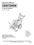
CRRFTSMRN®
8 HORSEPOWER
26" DUAL STAGE
120V. ELECTRIC START
SNOW THROWER
• Assembly
• Operation
• Customer Responsibilities
• Service and Adjustments
• Repair Parts
SEARS, ROEBUCK AND CO., Hoffman Estates, IL 60179 U.S.A.
SAFETY RULES
A
,L
CAUTION:
ALWAYS DISCONNECT
PLACE WIRE WHERE
IT CANNOTt
SPARK PLUG WIRE AND
CONTACT
SPARK PLUG
A
TO
PREVENT
AOO,DENTAL
START.NG
W.EN
SETT,.G
UP
TRANSPORT,N
ADJUST,N
OR
MAK,N
REPA,RS
AL
IMPORTANT
SAFETY STANDARDS
REQUIRE OPERATOR PRESENCE CONTROLS
TO MINIMIZE THE
RISK OF INJURY. YOUR SNOW THROWER IS EQUIPPED WITH SUCH CONTROLS. DO NOT
AI-FEMPT TO DEFEAT THE FUNCTION OF THE OPERATOR PRESENCE CONTROL UNDER
ANY CIRCUMSTANCES.
TRAINING
1.
2.
Read the operator's
manual carefully. Be
thoroughly familiar with the controls and the
proper use of the snow thrower. Know how to
stop the snow thrower and disengage the
controls quickly.
Never allow children to operate the snow thrower
and keep them away while It Is operating. Never
allow adults to operate the snow thrower without
proper Instruction. DO not carry passengers.
3.
Keep the area of operetlon clear of all persons,
particularly small children, and pets.
4.
Exercise caution to avoid slipping or falling,
especially when operating In reverse.
6.
Adjust the snow thrower height to clear gravel or
crushed rock surfaces,
7.
Never aftempt to make any edjustmsnts while the
engine (motor)
Is running
(except when
specifically recommended by the manufacturer).
8.
Let engine (motor) and snow thrower adjust to
outdoor temperatures before starting to clear
SNOW.
9.
Always weer safety glasees or eye shields du ring
operetlon or while performing an adjustment or
repair to protect eyes from foreign objects that
may be thrown from the snow thrower.
OPERATION
1. Do not put hands or feet near or under rotating
parts. Keep clear of the discharge opening at all
times.
PREPARATION
1. Thoroughly Inspect the area where the snow
thrower Is to be used and remove all doormats,
sleds, boards,wires, and other foreignobjects.
2. Disengage all clutches and shift Into neutral
before starting the engine (motor).
2.
Exercise extreme cautio n when operating on or
crossing gravel drives, walks, or roads. Stay alert
for hidden hazards or traffic.
3.
After striking a foreign object, stop the engine
(motor), remove the wire from the spark plug,
disconnect
the cord on electric
motors,
thoroughly Inspect the snow thrower for any
damage, and repair the damage before restarting
and operating the snow thrower.
If the snow thrower should start to vibrate
3. Do not operetethe snowthrowerwithoutweadng
adequate winter outer garments.Wear footwear
that will Improve footingon slipperysurfacse.
4. Handle fuel wIth care; it Is highlyflammable.
(a) Use an approvedfuel container.
4.
(b) Never remove fuel tank cap or add fuel to a
running engine or hot engine.
abnormally,
stop the (motor)
and check
Immediately for the cause. Vlbretlon Is gsnerelly
a warning of trouble.
(c) Fill fuel tank outdoors with extreme care,
Never fill fuel tank Indoors.
5.
Stop the snglne (motor) wheheveryou leavethe
operating position, before unclogging the auger/
Impeller housing or dlsnherge guide, and when
making a ny repairs, adjustments, or Inspections.
6.
When cleaning, repairing, or Inspecting, make
cartaln the auger/impeller and all moving parts
have stopped. Disconnect the spark plug wire
and keep the wire away from the plug to prevent
accidental starting.
Take all possible precautions when leaving the
snow thrower unattended. Disengage the auger/
Impeller, shift to neutral, stop engine, and
remove key.
(d) Replace fuel tank cap securely and wipe up
spilled fuel.
(e) Never store fuel or snow thrower with fuel In
the tank Inside of a building where fumes may
reach an open flame or spark.
(f) Check fuel supply before each use, anowlng
space for expenslonas the heatofthe engine
(motor) and/or sun can cause fuel to expend.
7.
5. Use extsnsloncords snd racaptaclesas specified
by the manufacturer for all snow throwers with
eiactrlc drive motors or electric starting motors.
2
SAFETY RULES
8.
9.
MAI'NTENANCE AND STORAGE
DO not run the engine indoors, except when starting
the engine and for transporting the snow thrower In
or out of the building. Open the outside doors;
exhaust fumes are dangerous (containing CARBON
MONOXIDE, an ODORLESS and DEADLY GAS).
1.
Check shear bolts and other bolts at frequent
improper tightness to be sure the snow thrower
is In safe working condition.
2. Never store the snow thrower with fuel in the fuel
tank inside a building whers Ignition sourcee are
present such as hot water and space heaters,
clothes dryers, and the llke. Allow the engine to
cool before storing In any enclosure.
Do not clear snow across the face of slopes.
Exercise caution when changing direction on
slopes. Do not attempt to clear steep slopes.
10. Never operate the snow thrower without proper
guards, plates or other safety protective devices
In place.
11. Never operate the snow thrower near glass
enclosures,
automobiles,
window
wells,
drop-offs, and the like wit hour proper adjustment
of the snow discharge angle. Keep children and
pets away.
12. Do not overload the machine
capacity
attempting to clear snow at too fast a rate.
3.
Always •refer to operator's manual instructions
for Important details If the snow thrower is to be
stored for an extended period.
4.
Maintain or replace safety and Instruction labels,
as necessary.
Run the snow thrower a few minutes after
throwing snow to prevent freeze-up of the auger/
impeller.
5.
by
13. Neveroperatethesnowthrowerat
hlghtransport
speeds on slippery surfaces. Look behind and
use care when becking.
WARNING
This snow thrower Is for use on sidewalks,
driveways, and other ground level surfaces.
14. Never direct dlscherge at bystanders or allow
anyone In front of the snow thrower.
CAUTION should be exercised while using on
steep sloping surfaces. DO NOT USE SNOW
THROWER ON SURFACES ABOVE GROUND
LEVEL such as roofs of residences, garages,
porches or other such structures or buildings.
15. Disengage power to the augerllmpeller when
snow thrower Is transported or not In use.
16. Use only sttachments and accessories approved
by the manufacturer of the snow thrower (such
as tire chains, electric start kits, etc.).
17. Never operate the snow thrower without good
vlslblnty or light. Always be sure of your footing,
and keep a firm hold on the handles. Walk; never
run.
II _
LOOK I_OR THIS SYMBOL TO POINT ouT
IA
IMPORTANT SAFETY
MEANS--ATTENTIONll!
PRECAUTIONS. IT I
BECOME ALERTt!!
YOUR SAFETY IS INVOLVED.
3
TABLE OF CONTENTS.
OPERATION
..........................................
10-15
SERVICE
AND ADJUSTMENTS
........... 19-25
S'_ORAGE ...................................................
26
TROUBLE
SHOOTING
...............................
27
REPAIR PARTS CSNOW THROWER)...28-38
REPAIR PARTS (ENGINEI ....................
39-42
PARTS ORDERING/SERVICE
................... 44
SAFETY RU LES ........................................
2,3
PRODUCT
SPECIFICATIONS
......................
4
CUSTOMER
RESPONSIBILITIES
..... 4,16-18
WARRANTY
.................................................
4
TABLE OF CONTENTS
..............................
5
INDEX ...........................................................
5
ASSEMBLY
................................................
6-9
INDEX
A
Adjustment:
Auger ............................................. 24
Belts............................................... 20
Belt Guide ...................................... 22
Cable ............................................. 20
Carburetor ..................................... 24
FrictionWheel ................................ 22
Spark Plug ...;................................. 25
Traction and Auger ........................ 20
Assembly:
Check List ........................................ g
Crank Assembly .............................. 8
Headlight ......................................... 9
Skid Height Adjustment ............. 7, 19
Unpacking........................................ 7
B
Belts:
Adjust Belts.................................... 20
Belt Guide Adjustment................... 22
Belt Maintenance ..................... 20, 21
Replace Belts ..;................ :............ 20
C
Cables. Clutch .......................... 7. 9, 20
Carburetor: ................................. 24, 26
Choke ......... _.................... t0, 1t, 13,14
Clutch, Auger ................... 1O, 11, 13,14
Clutch, Traction ............... 10, 11, 13,14
Controls:
Engine .......................... 10, 11, 13,14
Snow Thrower ........................ 10. 11
Crank:
AdjustingRod ............................ 8, 19
Assembly ......................................... 8
Operation ........................................ 10
Customer Responsibilities........ 4.16-18
Agreement ....................................... 4
Auger Gear Box ............................ 18
Auger Shaft ................................... 17
Engine ........................................... 18
General Recommendations .......... 16
Hex Shaft and Gears ................ 17-18
Spark Plug..................................... 18
O
Deflector, Snow Chute ......... I0. t 1.15
E
Electric Starter ................................. 13
Engine:
Control .................... 10. 11, 13, 14,15
Oil CaD .............. "...................... 12. 18
Oil Change ..................................... 18
Oil Level ............................. L.... 12, 18
• OilType ............................... _. 12. 18
Speed Governor ............................ 24
Starting the Engine ................... 13,14
Storage ........................... :.............. 26
F
Fuel, Type .................................... 4, 12
Fuel. Storage .............................. 13, 26
Friction Wheel:
Adjustment ..................................... 22
Replacement ................................. 23
G
Gears:
Auger Gear Box ............................. 18
Hex Shaft ....................................... 18
H
Handle, Upper and Lower .................. 7
Headlight............................................. 9
Height Adjust Skids ...................... 7. 19
Hex Shaft ......................................... 18
I
Ignition, Key..................... 10. 11, 13,14
Index ......... :........................................ 5
L
Levers:
Auger Drive Clutch ........ 7, 10, 11, 17
Choke ........................... 10, 11, 13,14
Shifter ...................................... 10, 11
Throttle Control ............ 10, 11.13, 14
Traction Drive Clutch ..... 7, 10, 11, 14
Lubrication:
Auger Gear Box ........................ 17-18
Auger Shaft .................................... 17
Disc Drive Plate ............................. 18
Engine ........................................... 18
• Hex Shaft and Gears ............... :..... 17
O
Oil:
Engine ................................. 4, 12, 18
Extreme Cold Weather ............. 12,18
Storage ..................................... ;.._26
Type ..................................... 4.12, 18
Operation:
Engine Controls ............ 10. 11.13,14
Lockout Pin. Wheel ........................ 12
Operating Snow Thrower ...................
....................................... 10, 11.13,14
Snow Throwing Tips ...................... 15
Starting the Engine ................... 13.14
Snow Throwar Controls ........... 10.11
5
P
Parts ............................................ 28-41
Primer Button .................. 10, 11, 13,14
R
Repair/Replacement Parts .......... 28-42
Recoil Starter ................................... 14
Replacements:
Auger Shear Bolt ...................... .....24
Belts............................................... 20
FrictionWheel ............................... 22
S
Safety Rules ................................... 2. 3
Service and Adjustments:
Auger Housing Height ............... 7, 19
Auger Shear Bolt ........................... 24
Belts......................................... 20. 21
Belt Guide ....................... ............... 22
Belt Replacement .......................... 21
Cable ..................................... 7. g, 20
Carburetor ............................... 24, 26
Chute Crank .................................. 19
FrictionWheel .......................... 22, 23
Scraper Bar ................................... 19
Spark Plug ..................................... 25
Service Recommendations .............. 27
Spark Plug .................................. 18, 25
Specifications ..................................... 4
Speed Governor ............................... 24
Startingthe Engine ...................... 13,14
Stopping the Engine ................... 11, 13
Stopping the Snow Thrower ............. t 1
Shipping Carton .............. ................ 6, 7
Skid Height ................................... 7, 19
Shifter Lever ................................ 10.11
Shear Bolts ....................................... 24
Storage ............................................. 26
T
Table of Contents ............................... 5
Tire Pressure .................................... 19
Trouble Shooting Chart .................... 27
Tools for Assembly ............................. 6
Traction Drive Belt .................. ..... 20,21
W
Warranty ............................................. 4
Wheel. Lockout Pin .......................... 12
CONTENTS OF HARDWARE PACK
:ONTENTS OF PARTS BAG
@
©
1 - 5/16 In. Lockwasher
1- 5/16 In. Hex Nut
"2 - Spare Shear Bolts
(1/4-20 x 1-3/4 in.)
H@
@
*2 - Spare Spacers
1 -5/16 In. Flatwashers
1 "Owner's
*2 - Spare 114- 20 Locknuts
iiIIIIIn
Parts packed separately
I
I
I
I
I
iiinlllllllllllllllllllllllll
1 - Starter Moto! Cord 10Ft.
>
II IIIIIIIInlllllllllllll
2- Cable _es
*Non-Assembly Parts
I
1- 5/16-18 x 1-3/4 In. Hex Head Bolt
manual
In carton (not shown full size)
I
I
1 - €ontainer5W30 oli
1 - Upper Handle
1-Parts _
1-Crank Assembly
2 - IgnitionKeys
(Attached to engine in plastic bag)
6
SERVICE
AND ADJUSTMENTS
CAUTION: ALWAYS DISCONNECTTHE
SPARK PLUG WIRE AND TIE BACK
AWAY FROMTHE PLUG BEFORE MAKING ANY ADJUSTMENTS OR REPAIRS.
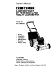
SKID MOUNTING NUTS
TO ADJUST SKID HEIGHT
Thissnowthroweris equippedwithtwo heightadjustment
skids,located on the outside of the auger housing(See
Fig. 20).These skidselevatethefront of thesnowthrower.
AUGER HOUSING
For normalhard sudaces, adjustthe skids as follows:
•
Check tirepressure(14 to 17 pounds).See sideoftire
for maximuminflation.Do notexceed maximumpressure on side of tire.
•
Place the extra shear bolts supplied (found in parts
bag) under each end of the scraperbar near but not
underthe skid.
•
Loosen the skid mounting nuts (See Fig. 20) and
adjust the skids up to bring the front of the snow
throwerdown. Re-tightenthe mounting nuts.
•
Set the skid on the other side at the same height.
FIG. 20
A
Forrockyor uneven surfaces,adjustthe skidsas follows:
•
HEIGHTADJUSTSKID
Raise the front of the snow thrower by moving the
skids down. This will help prevent rocks and other
debrisfrom beingpickedup and thrownbythe auger.
CAUTION: BE CERTAIN TO MAINTAIN
PROPER GROUND CLEARANCE FOR
YOUR PARTICULAR
AREA TO BE
CLEARED. OBJECTSSUCH ASGRAVEL,
ROCKS OR OTHER DEBRIS, IF STRUCK
BY THE IMPELLER, MAY BE THROWN
WITH SUFFICIENT FORCE TO CAUSE
PERSONAL INJURY, PROPERTY DAMAGE OR DAMAGE TO THE SNOW
THROWER.
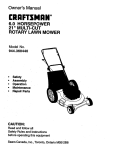
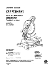
TO ADJUST CHUTE
CRANK ASSEMBLY
NOTE: Be surethatsnowthrower isset at same heighton
both sides.
Ifyou cannot rotate the chute crankfully tothe leftand to
the dght,you need to adjustthe chutecrank (See Fig.21).
TOADJUSTSCRAPER
BAR
After considerableuse, the metal scraper bar willhave a
definitewear pattern. The scraperbar in conjunctionwith
the skids shouldalwaysbe adjustedto allow1/8" between
the scraperbar and the sidewalkor area to be cleaned.
The scraper bar may have to be returned to its original
lowersettingto maintaintheoriginalperformancelevel.To
adjust:
•
Positionthe snow thrower on a level sudace.
•
Make sure both tires are equally inflated.
•
Loosen the carriage bolts and nuts securing the
scraperbar to the auger housing.
•
Adjustthe scraper bar to the properposition.
•
Tightenthecarriage bolts and nuts,making sure that
the scraperbar is parallelwith the workingsurface.
•
Loosen both 1/2" nuts on the crank adjusting rod
(using3/4" wrenches).
•
Rotate the adjustingrod in or out to allowabout 1/8"
clearance between the notch in the flange and the
outerdiameter of the worm.
•
Once this clearance is set, tigtltenthe nuts.
NOTE: Be sure the crank does not touchthe side of the
engine or the cover will be scratched.
_
NOTCHED SECTION
PLASTIC
CAP COTTER
For extended operation, the scraper bar may be
reversed. Ifthe scraper bar must be replaced due to
wear, remove thecarriage bolts and nuts and installa
new scraperbar.
"_-
FLATWASHER
1/2 INCH
CRANK ADJUSTING ROD
WORM
FIG, 21
i9
SERVICE AND ADJUSTMENTS
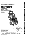
TO ADJUST THE CLUTCH CONTROL
CABLES
•.UGEn
0.,VE .
' LEVER
_'_
_1 FORWARDPOSITION
.T
Periodic adjustmentof the cables may be required due to
normalstretch and wear on the belts. Tocheckfor correct
adjustment, disconnect "Z" Fittingat clutch lever, move
clutch lever to the full forward position, just contacting the
plastic bumper. The control cables are correctly adjusted
when the center of the "Z" fitting is between the center and
top of the hole and there is no droop in the cable (See Fig.
22). If adjustment is necessary:
•
Remove fuel from tank, and stand blo_'er on end.
•
Pull rubber boot off the top of the spring. Push the
cable through the spring(See Fig. 23) to expose the
threaded portionof the cable.
•
Hold the squareend ofthethreadedportionwithpliers
and adjustthe Iocknutin or out until theexcess slack
is removed.
•
PuUthe cable back thmughthe spring and connectthe
cable.
•
Do the same for the other lever cable, if needed•
"Z"FITTING
|
/
"I-
_
(Just Contacting
,_
PlaslicBumper)WHEN
P ,,oau.PEn
FIG. 22
i
OAaLESPR,NG\
L
.__
LOCKNUT
NOTE" Whenever the traction drive or auger belts are
adjusted or replaced, the cables will need to be adjusted.
FIG. 23
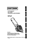
TO ADJUST BELTS
ii
Beltsstretch during normal use. If you need to adjustthe
belts due to wear or stretch, proceed as follows:
_
AUGER DRIVE BELT (See Fig. 25)
AUGER DLER
PULLEY "_
If your snow thrower will not dischargesnow,check the
control cable adjustment. If it is correct, then check the
condition of the auger drive belt. It may be loose or
damaged. Ifit isdamaged, replaceit. See To ReplaceBelts
paragraph on p_ge 21. If the auger drive belt is loose,
adjust as follows:
•
Disconnectthe spark plugwire.
•
•
Remove the belt cover (See Fig. 26).
Loosen the nut on the idler pulley (See Fig. 24) and
move the pulleytoward the belt about 1/8".
•
TKjhtenthe nut.
•
Pressthe augerdrive lever.Check thetensionon the
belt (opposite auger idler pulley). The belt should
deflect about 1/2" with moderate pressure (See Fig.
24).
ENGAGED
DRIVE
_'_-,,/_
•
_
,_
)_..._""
PULLEY
1/2 INCH
_
_,
i
:
/"-"
_
EFLECTION
IMPELLER
PULLEY
FIG. 24
NOTE: You may have to move the auger idler.pulley
mere than once to obtain the correct tension.
•
Replace the belt cover.
•
Check the clutchcontrolcable adjustment.
•
Reconnect the spark plug wire.
TRACTION
DRIVE
FIG. 25
BELT
•
The tractiondrive belt has constantspringpressure and
_doesnot require adjustment.
2O
Replace the tractiondrive belt if it is slipping(see To
Replace Belts paragragh on page 21 ).
SERVICE AND ADJUSTMENTS
t
TO REPLACE BELTS
\
The drive belts on this snow thrower are ot special
constructionand should be replaced with originalequipment belts available from your nearest Sears Store or
Service Center.
BELT COVER
/
You will need the assistanceof a second person while
replacing the belts.
Drainthe gasolinefrom the fuel tar¢_by removingthefuel
line at the carburetor.Drain the gas intoa containerand
reinstallthe fuel line.
TAPPINGSCREW
IA
DOORS,
FROM
OR FLAME.
CAUTION:AWAY
DRAIN
THEFIRE
GASOLINE
OUT" I
FIG. 26
TRACTIONDRIVEBELT
AUGER DRIVE BELT
If your snow thrower will not discharge snow, and the
auger drive belt is damaged, replace itas follows:
•
Disconnectthe spark plugwire.
•
Remove thebelt cover (See Fig. 26).
•
Loosen the belt guides (See Fig. 27) and puil away
from the engine drivepulley.
•
Loosen nut on the idler pulley(See Fig. 27) and pull
idlerpulley away from the belt.
AUGER DRIVE BELT
PULLEY
PULLEY
BELTGUIDE
(Left Hand)
BELTGUIDE
(Right Hand)
AUGER IDLER
PULLEY
TRACTION DRIVE
IDLER PULLEY
Remove belt from engine drivepulley.
Remove top two boltsthat secure auger housingto
motormount frame. Loosenbottom two bolts. Auger
housingand motor mount framewillseparate,hinged
by bottom two bolts. (See Fig. 29).
•
Disconnectthe spark plug wire.
Remove the belt cover,
Remove brake arm from housing. Do not remove
spring.
•
Remove bid belt from the auger drivepulley.
•
Positionnew belt on auger pulley.
•
Reinstallbrake arm intohousing.Ensurebrakearm is
fully inserted into housingand brake pad is riding in
pulley groove.
•
FIG. 27
Loosen the belt guides and pull away from engine
drive pulley.
Loosen nut on auger idler and pull auger idler pu!ley
away frombelt.Note location of Idler pulley for later
re-Installation.
Remove auger drive belt from enginepulley,
Pullthe drivebelt idlerpulley away from the drivebelt.
Replace top two bolts, and re-tighten bottom two
bolts.
•
Adjustthe drive belt (see To Adjust Auger Drive Belt
paragraph on page 20).
•
•
Adjustthe belt guides (see To AdjustThe Belt Guides
paragraph on page 22).
Reinstallthe belt cover.
•
Reconnect the spark plug wipe.
TRACTION
DRIVE
Remove the drive belt,
Positionnew drive belt onto tractionpulley.
Pull idler pulley away from belt, allowing belt to be
positioned onto engine pulley.
Release idler pulley. Ensure idler pulley is properly
engaged with belt.
Reinstall auger drive belt.
Adjust the belt guides and tighten mounting screws
(see To Adjust The Belt Guides paragraph on page
22).
BELT (See Fig. 27)
If your snow thrower will not move forward, check the
tractionddve beltfor wear. (Check otherc.ausesalsointhe
Trouble ShootingPointssection.)If the tractiondrivebelt
needs to be replaced,proceed as follows:
Adjust idler on auger belt.
Reinstall the belt cover.
Reconnect the spark plug wire.
21
SERVICE AND ADJUSTMENTS
TO ADJUST THE BELT GUIDES
MOTOR MOUNT FRAME
There are two beltguides on yoursnow thrower, a leftand
right.After you replace the traction drivebelt, you need to
adjust one or both of the belt guides. Proceed as follows
for each bolt:
•
Disconnectthe spark plugwire.
Remove the bolt cover (See Fig. 26).
Engage the auger drive clutchlever.
Measurethe distancebotween the beltguidesend the
belt (See Fig. 28). The distance shouldbe 3/32" for
each guide.
•
LOOSEN BO'R'OM BOLTS
•
Reinstallthe bolt cover.
•
Reconnect the spark plug wire.
.
(EACH SIDE)
If adjustment is necessary, loosen the belt guide
mounting bolts. Move the belt guides to the correct
position.Tighten the mounting bolts.
(Bottom View)
FIG. 29
•
Move frictionwheel toproper positionas indicatedin
previousstep (Fig. 29A).
•
Re-tightenbolts in speed selector lever.
•
Reinstallthe bottompanel.
BELTGUIDE
eEL'
(Right Hand)
FRICTION
SHAFT
/
FIG. 28
FIG. 29A
TO ADJUST THE FRICTION WHEEL
If the snow thrower _11 not move forward, you need to
check the tractionddve bolt, the tractiondrivecable or the
frictionwheel. If the frictionwheel is damaged, itwill need
to be replaced, See the To Replace FdctionWheel paragraph on page 23. If the fdctionwheel is not worn, check
the adjustment,as follows:
•
Disconnectthe spark plug wire.
•
Drain the gasolinefrom the gas tank.
•
Stand snow thrower on the auger housingend.
•
Remove the bottompanel (See Fig. 29).
•
Positionthe shitterlever in first (1) gear.
SPEED SELECTOR LEVER
FIG. 29B
Note the positionof the fdctionwheel on thedisc drive
plate, The dghtouterside ofthe discdriveplateshould
be 3" from the center of the tdction wheel (See Fig.
29A).
If adjustment is necessary:
•
Loosen bolts in speed selector lever (See Fig. 29B).
22
SERVICE AND ADJUSTMENTS
TO REPLACE
FRICTION
WHEEL
If the snowthrower willnot move torward,and the friction
wheel is worn or damaged, you need to replace it as
follows:(First allow the engine to cool.)
BE.
OVE
=_
_
'
BOTTOM
PANEL
LOOSEN
BOLT
•
Drainthe gasolinefrom the luel tank by removingthe
fuel lineat the carburetor.Drain the fuel in a container
and reinstallthe fuel line.
•
Disconnectthe spark plug wire.
•
Standthe snowthrowerup onthe augerhousingend.
•
Remove the bottompanel (See Fig. 30).
•
Remove the three (3) fasteners securingthe friction
wheel to the hub (See Fig. 31).
•
Remove the four bolts securing the bearing plates
(both sides). (See Fig. 32).
•
Remove rightside bearing plate. Leave hox shaft in
originalposition.
•
Remove frictionwheel from hub. Slipfrictionwheel ofl
hex shaft towards right side.
•
Slip new friction wheel onto hub with recessed or
cupped end away from hub. (See Fig. 31).
•
FIG. 30
FRICTION WHEEL
LOCKWASHER
SOLT.1"i
HEX SHAFT
BOLT
Installhearing plates to originalposition.Ensure hex
shaft is engaged with both bearing plates.
•
Secure bearing plates, usingbolts removed earlier.
•
Secure frictionwheel to hubusingfasteners removed
earlier.Ensure hex shaftturns freely.
Replace bottom panel
•
Lower the snow thrower onto the tires.
LOCKWASHER
FIG. 31
FRICTION WHEEL
\
• NOTE: Ensurefriction wheel and friction discare treefrom
grease or oil.
•
"
\
HEX SHAFT
HUB
/
BEARING
PLATE
BOLTS
BEARING
BOLTS
FASTENERS
-"'--"-AUGER
(UNITSTANDING ON
AUGER HOUSING END)
FIG. 32
23
SERVICE AND ADJUSTMENTS
TO REPLACE AUGER SHEAR BOLT
The augers are secured to the auger shaft with special
bolts (See Fig. 33) that are designed to break (to protect
the machine) if an object becomes lodged in the auger
housing. Use of a harder bolt will destroy the protection
provided by the shear bolt.
IMPORTANT: TO
INSURE
SAFETY
AND
PERFORMANCE
LEVELS, ONLY
ORIGINAL EQUIPMENTSHEAR BOLTS
SHOULDBE USED.WHEN REPLACING
SHEAR BOLTS, BE SURE TO REPLACE
SHEAR BOLT SPACERS..
•
SHEAR BOLT ._
SHEARsPAcERBOLT
Q
i
g
i
n
I
LOCKNUT
To replace a broken shear bolt, proceed as follows:
Move the throttleto STOP and turn off all controls.
FIG. 33
Disconnectthe spark plug wire. Be sure all moving
parts have stopped.
CARBURETOR
Lubricatethe auger shaft zerk fitting (see the Customer Responsibilitiessectionon pages 16-18).
Aifgn the hole in the auger with the hole in the auger
shaft, Install the new shear boif and shear bolt spacer
provided.
•
_IDLE
ADJUSTING SCREW
(Close finger tight only)
Reconnectthe spark plug wire.
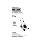
TO ADJUST CARBURETOR
HIGH SPEED ADJUSTING
SCREW
BOWL DRAIN
The carburetor(See Fig. 34 and Fig. 36, Page 26) has
been pre-setatthe factoryand readjustmentshouldnot be
necessary. However, if the carburetor does need to be
adjusted,proceed as follows:
•
FIG. 34
•
Closethe highspeed adjustingscrew by hand.
•
Do not over-tighten.
•
Then open it 1-1/4 to 1-1/2 turns.
•
Close the idle adjusting screw by hand. Do not overtighten.
•
Then open it 1-1/4 to 1-1/2 turns.
•
Startthe engine and let it warm up.
(Close finger tight only)
If the engine tends to stall under load or does not
accelerate from low speed to high speed properly,
adjust the high speed screwout in 1/8 turn increments
until the problem is resolved. Let the engine run!or30
secondsbetween settings.
IMPORTANT:
Set the throttlecontrol to RUN. Adjustthe high speed
adjustingscrew In untilthe engine speed or sound
alters. Adjust the screw out until the engine speed
sound alters. Note the difference I_etween the two
limitsand set the screw in the middle of the range.
Letthe engine run undisturbedfor 30 seconds after
each settingto allowthe engine to react to the previous adjustment.
Set the throttle control to SLOW. Adjust the idle
adjustingscrewIn untilthe engine speed drops,then
adjustthe screw out until the engine speed drops.
Note thedifferencebetweenthe two limits and set the
screw in the middle of the range.
24
NEVER TAMPER WITH THE ENGINE.
GOVERNOR,WHICH IS FACTORYSET
FOR PROPER ENGINE SPEED.
OVERSPEEDING THE ENGINE ABOVE
THE FACTORY HIGH SPEEDSETTING
CAN
BE DANGEROUS. IF YOU
THINK THE ENGINE,
GOVERNED
HIGH SPEED NEEDS ADJUSTING,
CONTACT YOUR NEAREST SEARS
SERVICE CENTER, WHICH HAS THE
PROPER
EQUIPMENT
AND
EXPERIENCE
TO MAKE ANY
NECESSARY ADJUSTMENTS.
SERVICE AND ADJUSTMENTS
TO ADJUST OR REPLACE
THE SPARK PLUG
Ifyou have difficultystartingyour snow thrower,you may
need to adjust or replace the spark plug. Follow the
instructionsbelow.
Replace the spark plug if the electrodes are pitted or
burnedor ifthe porcelainis cracked.
TO ADJUS_
•
•
Clean the spark plug by carefullyscrapingthe electrodes (do not sand blast or use a wire brush).
FIG. 35
Be sure the spark plug is clean and free of foreign
material.Checkthe electrodesgap (See Fig. 35) with
a wire feeler gauge and reset the gap to .030 inch if
necessary.
TO REPLACE:
•
If you need a new spark plug, use only the proper
replacementspark plug (See page 4).
•
Set the gap to .030.
25
•
Beforeinstallingthespark plug,coatitsthreadslightly
with oil or grease to insureeasy removal
•
Tightenthe plug firmlyintothe engine.
•
Ifa torque wrenchisavailable,torquetheplugto 18 to
23 ft. - Ibs.
STORAGE
I
,&
CAUTION: NEVER STORE YOUR SNOW
THROWER INDOORS OR iN AN ENCLOSED, POORLY VENTILATED AREA
IF GASOLINE REMAINS IN THE TANK.
FUMES MAY REACH AN OPEN FLAME,
SPARK OR PILOT LIGHT FROM A FURNACE, WATER HEATER, CLOTHES
DRYER, CIGARETTE, ETC.
BOWL
DRAIN
To prevent engine damage (if snow thrower is not used
for more than 30 days) follow the steps below.
SNOW
THROWER
FIG. 36
STORAGE
•
Thoroughlyclean the snow thrower.
•
Lubrioate all lubrication points (see the Customer
Responsibilitiessectionon pages 16-18).
•
Be sure that all nuts, bolts and screwsare securely
fastened. Inspectall visiblemovingpartsfordamage,
breakage and wear. Replace if necessary.
•
Touch up all rusted or chipped paint surfaces:sand
lightlybefore painting.
•
Cover the bare metal pads of the blower housing
auger andthe impellerwith rust preventative,suchas
a spray lubricant.
CARI_URETOR
BOWL
ALWAYS FOLLOW INSTRUCTIONS ON STABILIZER CONTAINER.THEN RUN ENGINE AT LEAST
10 MINUTES AFTER STABILIZER IS ADDED TO
ALLOW MIXTURE TO REACH
CARBURETOR.
STORE SNOW THROWER IN A SAFE PLACE. SEE
WARNING ABOVE.
YOUcan keep your engine in good operating condition
during storage by:
•
Changing oil (See page 18).
•
Lubricaifng the piston/cylinderaraa. This can be done
by first removingthe spark plug and squirtinga few
dropsofclean engineoilintothe sparkplughole.Then
coverthesparkplughole with a rag toabsorb oilspray.
Next, rotatethe engineby pullingthe starterropefully
out two orthree times. Finally,reinstallsparkplugand
attach spark plug wire.
NOTE: A yearly checkupor tune-up by a SEARS Service
Center isa good way to insurethatyoursnow throwerwill
provide maximum performancefor the nextseason.
ENGINE STORAGE
OTHER
Gasoline must be removed or treated to prevent gum
depositsfrom formingin the tank, filter, hose, and carburetorduringstorage.Alsodudngstorage alcohol blended
•
q
.
gasohnethat usesett!anolor methanol(sometimescalled
gasohor) attracts water. It acts on the gasoline to form
acids whichdamage the engine.
•
Ifpossible, store yoursnowthrowerindoorsand cover
itto give protectionfrom dust and dirt.
•
Ifthe machinemustbe storedoutdoors,blockup the
snowthrowerto be sure the entire machine isoff the
ground.
•
•
Cover the snow thrower with a suitable protective
cover thatdoes not retain moisture. Do notuse plastic
or vinyl.
Toremove gasoline, runthe engine untilthe tank is
empty and the engine stops. Then drain remaining
gasolinefrom carburetor by pressingupwardon howl
drain located on the bottom of carburetor.(See Fig.
36).
•
Start theengine and run at SLOW (idle)speed untilthe
engine stopsfrom lack of fuel.
IMPORTANT: NEVER COVER SNOW THROWER
WHILE ENGINE AND EXHAUST
AREAS ARE STILL WARM.
Ifyou do not wantto remove gasoline,a fuel stabilizer
(suchas Craftsman FuelStabilizerNo.33500) may be
added toany gasolineleftin the tankto minimizegum
depositsand acids. If the tank is almost empty, mix
stabilizer with fresh gasoline in a separate container
and add some to the tank.
26
TROUBLE SHOOTING POINTS
TROUBLE
CAUSE
CORRECTION
Difficult starting
Defective spark plug
Water or dirt in fuel system
Replace defective plug.
Use carburetor bowt drain to flush and refill with fresh
fuel.
Englne runs erratically
Blocked fuel line or low on fuel
Clean fuel line: check fuol supply: add fresh
fuel (gasoline/oil mixture if 2 cycle engine).
Engine stalls
Unit running on CHOKE
Move choke lover to OFF position.
Engine runs erratically;
Water or dirt in fuol system
Use carbureter bowl drain to flush and refill with fresh
Loss of power
fuel.
Carburete_ out of adjustment
Excessive vibration
Adjust
Loose parts; damaged impeller
carbureter,
Step engine immediately and disconnect spark plug wire.
Tighten all bolts and make all necessary repairs. If vibration
continues, have the unit serviced by a competent repairman.
Unit fails to propel
Itself
Unit fails to
Drive bolt loose or damaged
Replace drive belt.
Incorrect adjustment of traclion
ddve cable
Adjust traction drive cable.
Worn or damaged frictionwheel
Replace frictionwhee}
Auger drive belt loose or damaged
Adjust auger drive belt: replace if damaged
Augercontrolcablenotadjusted
co.ec_y
Adjust auger control cable.
Shear bolt broken
Replace shear bott
Discharge chute clogged
Stop engine =mmediately and disconnect spark plug wire
dfaeharge snow
Clean discharge chute and inside of auger housing
Foreign object lodged in auger
Stop engine immediately and disconnect spark plug w_re
Remove object trom auger
Heedllght does not work
Loose wire connection
T_ghtenconneclJon.
Bulb burned out
Replace headlight bulb
27
CRAFTSMAN 2"6"SNOW THROWER 536.886621
HANDLE
ASSEMBLY
REPAIR
PARTS
ASSEMBLY
LEFT SIDE
1
ASSEMBLY 7
RIGHT SIDE
"
/
/
/
20
/
18
5
J
f
REF. KEY# 12
PAGE 30
m[
KEY#
1
2
3
4
5
S
7
B
10
[
I
I
I
I
I
I
I
I
PART#
321835-830
302900
120393
120638
120376
11261
301386-830
301387-830
1
I
1058
I" 3535
DESCRIPTION
KEY#
PART#
DESCRIPTION
11
12
13
14
15
16
17
18
19
20
4049
1579
579869
1673
1502
308146
580667-830
180077
580639-854
334220
BUMPER, RECTW/FLATTOP
BLK
CABLE, CLUTCH, 28.44L
SPRING, TENSION .58 x 5.83 x .1055
SPRING, AUGER CLUTCH, A20 DIA
NUT, 1/4-20 HEXNYL
BOOT, CLUTCH SPRING
HANDLE, LWR t6GA x 1,00
SCREW, 5/16-18 x .75 HHC
BRACKET, SHIFT PA'I-r ERN
OWNER'S MANUAL
HANDLE, UPPER, WIUGHT HOLE
SCREW, 5/16-18 x 1.75 HHC
FLATWASHER, .349 x .69 x .066
WASHER, SPTLK 31 x .58 x .08
NUT, 5/16-18 REGHEX
STOP. RED PLASTIC 5/16
HANDLE, RH ASSEMBLY
HANDLE. LH ASSEMBLY
PIN, CLUTCH HDLE OS
NUTr pUSH ON CAP .312 OO
!
319688[
28
;RAFTSMAN 26" SNOW THROWER 536.886621
CHUTE CONTROL ROD REPAIR PARTS
7
5
6
6__
:10
I\
1
_"
KEY#
PART#
DESCRIPTION
KEY#
1
2
3
4
5
6
7
5
3256O7
120394
121224
104
307399
309312
578159
71457
CRANK, ASSY CHUTE 35.5, LF
WASHER, FLAT .406 x .81 x .06
PIN, COTTER .094 DIA x 1.00 LG
CAP, PLASTIC, 3/8 ID
HANDLE, CHUTE CRANK, BLACK
WASHER, FLAT .39 x .70 x .05
RING, RET E .375 x .04TRU5115.37
BOLT, EYE 3/8-16 x 5.00.63 ID
9
10
11
12
13
14
15
16
17
PART#
148
308145
124829
309344
71046
585383-839
7O55
7058
120384
14
17 1'6 _
15
2 4
DESCRIPTION
GROMMET, EYE BOLT .40 ID x .435
BOOT, EYEBOLT CHUTE CRANK
NUT, 3/8-16 HEXJAM
ADAPTER, BOOT TO HANDLE
NUT, 3/8-16 HEXNYL
PLATE ASSEMBLY
ROD, CHUTE CONT 420T
NUT. 1/2-20 HXJAM
WASHER r REGSPTLK,523 x .87 x .14
-
DISCHARGE
i
334221
B
CHUTE REPAIR PARTS
16
KEY#
1
2
3
4
5
6
7
8
9
10
11
12
13
14
15
16
17
18
16
19
20
18
REF. KEY #12
PAGE 30
t
/
/.
PART#
DESCRIPTION
1502
120392
180020
302244
302172
310860
71032
71058
302275
585414
180016
307665
308931
582O8
30268O
1498
302843
302680
13527
120376
|
COLLAR, CHUTE ADAPT
NUT, I/4-20 REGHEXCTRLK
WASHER, FLAT
SCREW, 114-2OX .75
FLANGE, CHUTE
CUP. LWR CHUTE RING 6"
STOP, CHUTE LONG
SCREW, #8-32X .50
NUT, #8-32 HEXCTRLK
RING, FLANGED CH ROT PLAS
CHUTE, LWR SRS
SCREW. 114-20X 50
CHUTE. UPPER
WIRE, HINGE
SCREW. 5/16-18X75
WASHER. FLAT
NUT, 5/16-18
BOLT, 5/16-18X1 25 CARR
WASHER. FLAT
KNOB. T-W/518/18 NUT
NUT, 5/16-18
334218
29
B
CRAFTSMAN 26" SNOW THROWER 536.886621
AUGER
HOUSING
4-.TJ-L
S
ASSEMBLY
17 13
l,
9
REPAIR
PARTS
6
•
NOTE:
PAGE
!
36
I
8
'
,,,_,>
"_
.31
, +-9
t
:',
;_--_-11
i,,¢'
i
K_i
PART#
DESCRIPTION
KEY#
PART#
DESCRIPTION
1
2
3
4
5
6
7
6
9
10
11
12
13
14
15
16
583127
71371
71074
274654
583161
582960
49562
1_O077
12_93
120638
120376
333906-854
585526
122119
120382
1499
PULLEY, V4L 6.50 OD
KEY, SQUARE .18SQ x .88LG
FLA'IWASHER, .53 x 1.00 x .063
NUT_ 1/2-20 REGHXCTRLK
SPACER, SLEEVE .676 x 1.00 x .751
RETAINER, BALL
BEARING, BALL 6203-2AA(SEALS)
._3REW, 5/16-18 x .75 HHG
FLATWASHER, .349 x .69 x.066
WASHER, SPTLK .31 x.58 x .08
NUT, 5/16-18 REGHEX
HOUSING, ASSY AUG
BRACKEKTS & NUTS ASSEMBLY
SCREW, 3/8-16 x .75
WASHER, .393 x .68 x .10
NUT, 3,_-16
17
18
19
20
21
22
23
24
25
26
27
28
29
30
31
5848O9
_01106-e30
70993
302091-830
302090830
9524
3943
1502
313873
73755
35498
308070-854
308071-854
126358
50643-830
HUB, BRAKE ARM
BLADE, SCRAPER
BOLT, 5/16.18 x .75 CARRLN
AUGER ASSEMBLY, LH
AUGER ASSEMBLY, RH
SCREW, 1/4-20 x 1.75 HHCFT
SPACER, SLEV .250 x .47x .20
NUT, 1/4-20 REGHEXCTRLK
BEARING, AUGER SHAFT 1"ID
FLA'IWASHER, 1.005 x 1.31x .035
SCREW, 5/16-18 x .75WAHHTAP
PLATE, AUGER HOUSING, LH
PLATE, AUGER HOUSING. RH
BOLT. 5/16-18 x 1.00
SKID. HEIGHT ADJUST
1,
33439_B
Rf)
CRAFTSMAN
26" SNOW
THROWER
536.886621
SHIFT YOKE REPAIR PARTS
REF. KEY# 17
PAGE 28 _
I
\
"\
\
REF. KEY# 1
PAGE 33
\
\
!
8
g
/
7
3
REF. KEY# 12
PAGE 32
KEY#
PART#
1
2
3
4
5
6
7
8
g
581631-830
51332
1502
304438
318486
581630
579944
327065
1499
I
DESCRIPTION
ROD, SHIFT SELECTOR
SCREW, 1/4-20 x .63 WDFLLK
• NUT, 1/4-20 REGHEXCTRLK
KNOB, SHIFT 112-13
NUT, 1/2-13 HEXJAM
LEVER, SPRG SFT
BEARING, FL .5001D x ,88 OD x .31
ROD, ASSEMBLY SPD SEL
NUT. 3/8-16 HEXCTRLK
3!9053 B
31
CRA SMAN
26'; SNOW
ROWER
536. 6621
FRAME COMPONENTS REPAIR PARTS
K_#
PART#
DESCRI_
KEY#
PART#
DESCRIP_oN
1
2
3
4
5
6
7
8
9
I0
11
12
13
14
15
16
17
18
_1_
91 _
711_
_97
_1_
3101_
31_
71074
31_
580889
579874
7_ 1
_97
5_
4_92
1_
31_
415_
F_ME, _Y
ENG MT MID 92
SCR_,
_16-24 x 1._ HHC
NUT, _1_24 HE_DFLLK
_REW,
_16.18 x._WAHHTAP
COVER, _OM
W-1_-2,3
SCREW, 1/4-20 x .63 WAHHTAP
SPRING, IDLER _CTION
DRIVE
F_ASHER,
.53 x 1.00 x .0_
BRNG, F_NGE
SHAFT AUG CLUTCH, A_Y
_VER, A_Y AUGER CLUTCH C_
PiN, SPRING.I_
DIA x ._LG HD
N_, PUSH ON 1_
CABLE, ._
EYE 6.125 LG
SCR_,
_16
x 1.25 HHC
F_HER,
.406 x .81x .066
PULLEY, IDLER BFF 1._ x .75
NUT, _-16
C_L_AM
2WAY
19
20
21
22
23
24
25
26
27
28
29
30
31
32
33
34
35
5798_
1219_
1_92
1_2
580944
3_02
12_
_19
_15_
7_01
31_
57_
18_
73795
57_
710_
_0772
S_L,
CABLE AUGER CLUTCH
SCREW, 1/4-20 x 1.75 HHC_
F_ASHER,
.286 x .63 x .065
1/4-20 H_NYL
CAM, B_KE ARM
BOLT, 1/4-20 x .63 CARR
FLATWASHER, .344 x .69 x .065
ROD, BRAKE ARM (MID)
PAD, AUGEFI_MPELLER BRAKE
PIN, SPRING.165DIA x .88LG HD
SPRING, TENSION RETURN (7030)
LEVER, IDLER ARM TRACTION
SCREW, 5/16.18 x .75 HHC
FLATWASHER, .328 x 1.38 x .075
BUSHING. IDLER LEVER
NUT. 5/16-16 HEXNYL
COVER, BELT CO_MIDP_S
.
!
313_
F
CRAFTSMAN
26" SNOW THROWER
536.886621
ENGINE COMPONENTS REPAIR PARTS
7
9
11
5
12
15
REF. KEY# 1
PAGE 32
REF. KEY# 17
PAGE 34
KEY#
PART#
DESCRIPTION
2
3
4
5
6
7
8
9
10
11
12
13
14
15
3O2636
120638
3949
578733
579855
579854
579861
579932
7384O
313857
.3526
313826
120382
39573
T8HP 4CYL SRS
SCREW, 5/16-18 X 1.25 HHC
WASHER, SPTLK 31 x ,58 x .08
GUIDE, ROD BELT RH SF 8HP
SCREW, 5/16-24 x .625HHC
WASHER, CRANKSHAFT
PULLEY, HALF V3L 2.00 x .7521D
WASHER, FLAT ,752 x .91 x .02
BELT, V 31. 33.13LG
FLATWASHEP_ .765 x 1,12 x .06
PULLEY, ENG V4L 3.00 x 1.12
BELT, V 4L 30,7
FLATWASHER, .375 x 1.25 x .104
WASHER. HVSPTLK .38 ID
SCREW, 3/8-24 x 1,00 HHC
REF. KEY# 1
PAGE 30
" SEE ENGINE MANUAL
319042 E
33
3RAFTSMAN 26" SNOW THROWER 536.886621
DRIVE COMPONENTS
REPAIR PARTS
1
2
REF. KEY# 12
_.
PAG E 32
i.
17
/
18
/
/ 2O
/
21
\
22
31
22
KEY#
PART#
DESCRIPTION
KEY#
PART#
DESCRIPTION
I
2
3
4
5
6
579941
313853
137185
313919
579937
11871
1502
583164
583206
583155
85501
73812
73811
58O969
49562
58O970
LEVER, ASSY TRACT CLUTCH
BEARING, FLANGE
PIN, COTTER .125 DIA x 1.00LG
SPRING, RETURN
LEVER, SPRG TRAC CL
SCREW, 1/4-20 x ,63 HHCFT
NUT, 1/4-20 REGHEXCTRLK
DISC. ASSY FRICWHL
ZERK, GREASE .25-28 x 1,12LG
SHAFT, HEX TRACTION
BEARING, TRUNION 1.25 ID
FLATWASHER" .505 x 1.00 x ,06
RING, RETEXI.16 x .05TRU5100-1_
FLAI"WASH ER, ,680 x 1.12 X .060
BEARING, BALL 6203-2AA(SEALS)
KEY, SQUARE. 18SQ x .63 LG
17
18
19
20
21
22
23
24
25
26
27
28
29
30
31
580961
58O965
1084
120380
180020
334163
35497
120638
579858
331112
581773
313883
120375
579893
579867
PULLEY, V3L 6.50 x .56
WASHER. WAVE .675 x 1.00 x .020
WASHER, FLAT .281 x 1.00 x .063
WASHER. SPTLK .26 x .50 x .06
SCREW, 1/4-20 x .75 HHC
BEARING & RETAINER, ASSY
SCREW, 5/16-18 x .50WAHHTAP
WASHER, SPTLK .31 x .58 x .08
WASHER, SP .502 x .75 x .0605
SHAFT & SPROCKET, ASSY #40-8T
HUB, FRICTION WHEEL
WHEEL, FRICTION DISC 4,375 OD
NUT, 1/4-20 REGHEX
SPRKET & SHAFT. ASSY 8T&36T-41
CHAIN. ROLLER #42 x 40P
9
10
11
12
13
14
15
16
313995 E
CRAFTSMAN
26" SNOW THROWER
WHEEL ASSEMBLY
536.886621
REPAIR PARTS
"---0
7
9
5
11
/
6
9
4
7
;KEY#
3
4
5
6
7
8
9
10
11
12
PART#
DESCRIPTION
.580_3
583012
73839
1502
581730
579867
73840
578572
326465
577015
239
73642
SHAFT, AXLE WHEEIJMID
SPRk3" x HUB ASSY, _10 x 35T x .7510
SCREW. 114-20 x 2.25 HHC GRD8 SP
NUT, 1/4-20 HEXNYL
BEARING, FL .755 ID x 1.127OD x .75
CHAIN, ROLLER #42 x 40P
WASHER. FLAT .765 x 1.12 x .06
BEARING, FLANGE
TIRE & RIM, PU 13 x 5.0 x 6 HOG
SCREW, 1/4-20 x 1.50 HHCSP
RING, RET TRU5115-75
PIN. KLIK .25 x 1.38 DIA
318542 C
HEADLIGHT REPAIR PARTS
KEY#
2
3
:4
5
6
7
\
\\
\
•,
10
\
\
PART#
DESCRIPTION
307395
581575
58053O
307781
307767
403O
4160
580527
138485
120638
HOUSING. HEADUGHT UPPER
HEAOUGHT, ASSY #0530802
HOUSINGj HEADUGHT LWR 90
SCREW, #8 x 1.75 PHRDPST
BRACKET, LIGHT EXTENDED
BOLT. 5/16-18 x 1.75 CARR
WASHER. SADDLE 5/16
WASHER.
EXLK .32 x .60 x .04
WASHER. SPTLK .31 x .58 x .08
NUT, 5/16-18 REGHEX
SCREW. 5/16"18 x 2.00 HHCFT
\\
:
35
319374
B
CRAFTSMAN 26" SNOW THROWER 536.886621
GEAR BOX REPAIR PARTS
15
/
_4
j2
J
KEY#
PART#
DESCRIPTION
1
2
3
4
5
6
7
8
9
10
11
896
895
910828
71100
123785
313872
106,5
313870
313871
301561
897
CASE, GEAR RH 12"AJUG/IO-12"IMP
CASE, GEAR LH 12"AUPM10-12"IMP
SCREW, 5/16-24 x 1.00 HHC
NUT, ,5/16-24 HEXWDFLLK
SCREW, 5/16-24 x 1.50 HHC
PLUG, PIPE 114- 18
SEAL OIL CR 530552 #53744
BEARING, SLEEVE
FLATWASHER, 1.00 x 1.54 x .09
SHAFT, AUGER OUTPUT MF 12"
GASKET, GEAR BOX
rKEY#
PAP,Lll
12
13
14
313661
17
16
18
19
20
21
313828
9346
50795
313862
53731
585423-830
313914
DESCRIPTION
GEAR, WORM 22T 3.125 OD
KEY, WDRF #91.75DIA x .25WD
RING, QUAD .9241D x .t03WD
BEARING, FL .7531D x 1.128ODx1.03
FLA'rWASHER, ;752 x 1.24 x .093PL
BEARING, ROLL7501D x 1.24OO x .078
FLATWASHER, .752xl.24 x .093PL
KEY, HI-PRO 606 .75DIA x. 187WD
GEAR, WORM 1.75 OD
BEARING, SI-EVE .75210.8800 x .755
IMPELLER, ASSY MF 12"3 BLD 92
314014C
36
CRAFTSMAN 26" SNOW THROWER 536.886621
DECALS
3
HOUSING
4
7
7/8"
REAR VIEW
KEY#
PART#
DESCRIPTION
1
2
3
4
5
6
7
8
9
10
7376
70141
313892
302922
308766
334157
308768
3902
390_
319033
DECAL. 12"IMPELLER
DECAL. DANGERAUGER #11445
DECAL, DANGERCHUTE #10442
DECAL,DANGERENGUSH #11444
DECAL.CRAFTSMAN(RED) STEEL
DECAL,8/26 ELECTRIC START
DECAL,DANG STRIPE CHT SRS
DECAL,TRACTIONDRIVE ENGAGE
DECAL,AUGER DRIVE ENGAGE
DECAL,GEAR SELECTOR,COMPAC1
318796-3140051
37
CRAF;rSMAN
26" SNOW THROWER
536.886621
KEY#
PART#
DESCRIPTION
1
6218
6216
6217
6219
MOTOR. STARTER TEC 120V
SCREW, 1/4-20 x .50HWASEMSTOR
SCREW, #6-32 x 2.50 HHC
CORD. STARTER MOTOR
4
319051 A
38
CARBURETOR
NO. 632334 A
REF.
1
2
6
7
PART#
631776A
631970
631778
550506
10
14
15
16
17
18
20
21
22
23
25
632112
632174
630735
632164
650417
630766
"632281
630766
630739
"630740
631951
27
28
29
30
"631024
632019
"631028
"631021
31
32
33
40
631022
27136A
27554
"632239
41
"630740
42
630739
44
47
48
60
*27110
"630748
"631027
632347
PART NAME
THROTTLE SHAFT & LEVER ASSY
THROTTLE RETURN SPRING
THROTTLE SHUTTER
THROTTLE & CHOKE SHUTTER
SCREW
CHOKE SHAFT & LEVER ASSY
CHOKE SHUTTER
CHOKE POSITIONING SPRING
FUEL FITTING
IDLE SPEED SCREW
TENSION SPRING
IDLE MIXTURE SCREW
IDLE TENSION SPRING
WASHER, IDLE SCREW
"O" RING, IDLE SCREW
FLOAT BOWL ASSY
(INCL. NOS. 32 & 33)
SHAFT, FLOAT
FLOAT
"O" RING, FLOAT BOWL TO BODY
INLET NEEDLE. SEAT & CLIP
(INCL. NO 31)
SPRING CLIP
BOWL DRAIN ASSY
DRAIN PLUNGER GASKET
MAIN ADJ. SCREW ASSY
(INCL. NOS. 41 THRU 44)
"O" RING, HIGH SPEED MIXTURE
SCREW
WASHER, HIGH SPEED MIXTURE
SCREW
BOWL NUT WASHER
WELCH PLUG, IDLE MIXTURE WELL
WELCH PLUG, ATMOSPHERIC VENT
REPAIR KIT
(INCL. PARTS MARKED WITH ")
REWIND STARTER NO. 590672
REF.
I
2
3
4
5
6
7
8
11
12
13
39
PART#
590672
590599A
590600
590679
590601
590678
590680
590412
590682
590684
590456
PART NAME
STARTER, REWIND
PIN, SPRING (INCL NO4)
WASHER
RETAINER
WASHER
SPRING, BRAKE
DOG, STARTER
SPRING, DOG
PULLEY & REWIND SPRING ASSY
HOUSING ASSY, STARTER
ROPE, STARTER
(LENGTH 114': & .11/64" DIA.)
590574 HANDLE, MITTEN GRIP
(NOT INCLUDED WITH STARTER)
cRAFTSMAN
2'CYCLE ENGINE
MOI_EL
NUMBER143.948001
30
90
<
40
CRAFTSMAN 2-CYCLE ENGINE
REF.
PART#
PART NAME
1
2
3
4
5
15
15A
15B
16
17
18
20
25
26
28
30
35
36
37
38
40
40
40
41
35385
27652
650820
30968
30969
30699C
30700
650494
33454
29916
650548
35319
35326
650561
30322
36245
29826
29916
29216
29642
34552
34553
34554
34331A
CYLINDER (INCL. 2,20 & 72)
DOWEL PiN
SCREW, 1/4:20 X 1/2"
OIL DRAIN EXTENSION
EXTENSION CAP
GOVERNOR ROD (INCL. 15A & 15B)
GOVERNOR YOKE
SCREW, 6-40 X 5/16"
GOVERNOR LEVER
GOVERNOR LEVER CLAMP
SCREW, 8-32 X 5/16" OIL SEAL
BLOWER HOUSING BAFFLE
SCREW, I/4-20 X 5/8"
LOCKNUT, 8-32
CRANKSHAFT
SCREW, 10-32 X 2/4"
LOCK WASHER
LOCKNUT, 10-32
RETAINING RING
PISTON, PIN & RING SET (STD)
PISTON, PIN & RING SET (.010"OS)
PISTON, PIN & RING SET (.020"OS)
PISTON, PIN ASSEMBLY (.020"OS)
(INCL. 43)
PISTON & PIN ASSEMBLY (STD)
(INCL. 43)
PISTON & PiN ASSEMBLY (.010"OS)
(INCL. 43)
RING SET (STD)
RING SET (.010"0S)
RING SET (.020"OS)
PISTON PIN RETAINING RING
CONNECTION ROD ASSEMBLY
(INCL. 46, 47 & 49)
CONNECTING ROD BOLT
CONNECTING ROD BOLT
VALVE LIFTER
OIL DIPPER
CAMSHAFT (BCR)
BLOWER HOUSING EXTENSION
GROMMET MOUNTING BRACKET
SCREW, 8-32 X 3/8"
GROMMET
ISCREW, 10-24 X 1/2"
!CYLINDER COVER GASKET
_,YLINDER COVER
INCL. 71, 75 & 80)
CRANKSHAFT BUSHING
OIL DRAIN PLUG
OiL SEAL
GOVERNOR SHAFT
WASHER
GOVERNOR GEAR ASSEMBLY
(INCL. 81)
GOVERNOR SPOOL
41
3492A
41
34330A
42
42
42
43
45
34332
34333
34334
27888
35373A
46
47
48
49
50
60
61
62
63
65
69
70
650gQ8
850882
34034
35374
35375
33273A
34126
65076(
28545
650128
*35262
35376
71
72
75
80
81
82
35377
27642
35319
31845
30590A
35378
83
30588A
MODELNUMBER
143.948001
REF.
:84
86
89
90
92
93
100
101
102
103
110
110A
119
.120
125
125
126
126
127
129
130B
131A
135
139
140
149
149A
150
151
169
170
171
172
173
174
178
182
183
184
185
186
200
203
204
206
207
209
215
219
220
222
223
* INDICATES PARTS INCLUDED IN GASKET SERT, REF. NO. 40{)
_:
r
41
PART# PART NAME
29193
650833
32589
611093
650880
650881
35135
610118
650872
650814
35253
35305
"36448
36449
27880A
RETAINING RING
SCREW. 1/4-20 X1-11/16"
FLYWHEEL KEY
FLYWHEEL (W/RING GEAR)
LOCK WASHER
FLYWHEEL NUT
SOLID STATE IGNITION
SPARK PLUG COVER
SOLID STATE MOUNTING STUD
SCREW. TORX T-15. 10-24 X I_
GROUND WIRE
GROUND WIRE
CYLINDER HEAD GASKET
CYLINDER HEAD
EXHAUST VALVE (1/32, OS)
INCL. 151)
27878A EXHAUST VALVE (STD) INCL. 151)
34036 INTAKE VALVE (1/32" OS) (INCL. 151)
34035 INTAKE VALVE (STD) (INCL. t51)
650691 WASHER
650727 SCREW, 5/16o18 X 1-3/4"
6021A! SCREW, 5116-18 X 1-1/2"
650713 SCREW, 5/16-18 X 5/8"
35395 RESISTOR SPARK PLUG (RJ19LM)
33369 GOVERNOR GEAR BRACKET
650836 SCREW, 10-24 X 1/2"
27882 VALVE SPRING CAP
35862 VALVE SPRING CAP
27881 VALVE SPRING
32581 VALVE SPRING KEEPER
"27896A VALVE COVER GASKET
28423 BREATHER BODY
28424 BREATHER ELEMENT
28425 VALVE COVER
35350 BREATHER TUBE
650128 SCREW, 10-24 X 1/2"
29752 NUT & LOCK WASHER, 1/4-28
30088A SCREW, 1/4-28 X 1"
'
34587 CHOKE BRACKET
*33263 CARBURETOR TO INTAKE PIPE
GASKET
33871 INTAKE PIPE
34667 GOVERNOR LINK
34677 CONTROL BRACKET
(INCL, 203 & 204)
31342 COMPRESSION SPRING
650549 SCREW, 5-40 X 7/17"
610973 ;TERMINAL
33878 THROTTLE LINK
650823 SCREW, 10-32 X 1/2"
35440 CONTROL KNOB
34586 CHOKE ROD
35438 CHOKE KNOB
29820 SCREW. 10-32 X1/2"
650378 SCREW, TORX T-30.5!16-18 x 1-1/8"
CRAFTSMAN 2-CYCLE ENGINE
REF. I
MODELNUMBER143.948001
PART# PART NAME
224
260
261
262
264
266
275
276
277
281
282
285
286
287
291
292
298
300
301
305
306
308
310
314
315
"27915A
35447A
650788
29747B
650802
33272B
35056
31588
792093
33013
650760
34985A
35446
29752
30705
26460
650665
34156A
35355
35554
35499
35540
36205
650873
611111
623
625
327
611118
29443
3539;
INTAKE PIPE GASKET
BLOWER HOUSING
SCREW, 5/16-18 X 3/4"
SCREW, TORX T-40, 6/16-24 X 21/32"
SCREW, 1/4-20 X 5/8"
CYLINDER HEAD COVER
MUFFLER
LOCKING PLATE
SCREW, 5/16-18 X 4:3/16" ......
ST_,RTER BUBBLE COVER
SCREW, 8-32 X 3/8"
ST"ARTER CUP
STARTER SCREEN ......
NUT & LOCK WASHER. 1/4-28/64"
FUEL LINE-...................
FUEL LINE CLAMP
SCRI_W. 1/4:1"5"X"778
'_.....................
REF
328
329
335 •
336
338
340
341
342
350
351
355
364
365 _
370
370A
370B
380
_
_ _i:
FUEL CAP
OIL FILL TUBE
'O" RING
=ILL TUBE CLIP
DIPSTICK
SCREW, 1/4-20 X 3/4"
_LTERNATOR COIL (18 WA3-r)
[INCL. 323)
tERMINAL
_tIRE CLIP
STARTER PLUG
39o
396
400
PART# PART NAME
, 35593 SWITCH KEY
610973 TERMINAL
35057A CARBURETOR COVER
650765 SCREW, 10-32 X 1;2"
28942 SCREW, 10-32 X 3/8"
3415_ FUEL TANK BRACKET
34154 FUEL TANK BRACKET
650561 SCREW. 1/4-20 X 5f8"
570682 PRIMER ASSEMBLY
32180( PRIMER LINE
590574! STARTER HANDLE
33377 CARBURETOR COVER BRAGKE3
650767 SCREW. 8/32 X 27!64"
35077 ! CHOKE DECAL
34144 PRIMER DECAL
35878 WARNING DECAL
632334A' CARBURETOR (INCL 184)
590672 REWIND STARTER
XXXXXX ELECTRIC STARTER MOTOR KIT
143.88924 (OPTIONAL)
36450 GASKET SET
INCLUDES ITEMS MARKE['_ "i
RPM SETTINGS:
HIGH SPEED: 3550 TO 385O
LOW SPEED: 1700
* INDICATES PARTS INCLUDED IN GASKET SERT, REF. NO. 400
42