1
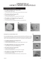
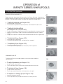
Note: Read all instructions before proceeding with installation. All specifications are ± 1/4’’ and are subject to change without notice. infinity SERIES Owner’s Manual & Installation Guide TABLE OF CONTENTS Table of contents Product Registration/Warranty Card Congratulations! 2 3 4 Safety Instructions Installation Instructions Pre-Installation Procedures Structural Preparation Leveling of the Infinity I Factory Installed Tile Flange Plumbing/Rough-In Measurements Fast Fill Waterfall Spout Continuous Waterfall Electrical Installation Chromatherapy LED Lighting 5 6 7-8 8 9 9-10 10 11 11-14 14 Operation Bathside Control Systems Jet Operations User Information FCC Information Serial Number - How to Locate 15-17 18-20 21 21 21 Maintenance and Care Initial Cleaning Whirlpool System Cleaning Air Bath System Cleaning Surface Cleaning Jet Cleaning Surface Scratch Removal Repair Information Water Quality Issues 22 22 22 23 23 23 23 23-25 Troubleshooting guide Symptoms/Possible Problems/Solutions parts order form/parts maps/parts list Parts Order Form Parts Maps Parts List aquatic limited warranty 2 26 27 28-31 32-33 34 Aquatic Aquatic Product Registration Information Your product warranty is registered and confirmed with Aquatic through the Serial Number on your unit. You do not need to contact Aquatic to confirm registration. Please fill out the information below and reference when contacting the distributor to expedite warranty claims. Owner Information: Model Name Serial Number (See Table of Contents for Location) Purchase Date Distributor 8101 E. Kaiser Blvd. • Anaheim, CA 92808 (800) 877-2005 • Fax (714) 998-5340 www.aquaticbath.com Aquatic 3 congratulations! You have chosen one of the finest bath products in the world! Aquatic supports your purchase with strong commitments to quality and customer satisfaction. Please read and follow all of the instructions contained in this Owner’s Manual before installing, operating or maintaining your whirlpool. In addition, you should continually refer to these instructions during the life of your whirlpool. Failure to comply with these instructions may invalidate your warranty. If you have any questions concerning installation, operation, maintenance or any other aspect of your whirlpool, please contact: Aquatic CUSTOMER SERVICE CENTER: 800-928-3707 (The Troubleshooting Guide on page 26 may be helpful in answering some of your questions.) NOTE: The installation and service of your whirlpool should be performed ONLY by a qualified electrician, technician or plumber. Important! This product must be water-tested and inspected prior to installation or warranty will be voided. See page 6 for instructions. PLEASE CHECK ENTIRE UNIT FOR any DAMAGE. If it appears damaged, contact your Aquatic Distributor immediately. Aquatic warranty does not cover damage that occurs in transit. IMPORTANT SAFETY INSTRUCTIONS warning: when using this unit, these basic precautions should be followed. This manual contains information and instructions for proper operation and maintenance of your whirlpool. Failure to follow these instructions could result in personal injury, electrical shock or fire. READ AND FOLLOW ALL INSTRUCTIONS danger! To reduce the risk of injury: A. Do not permit children to use this unit unless they are closely supervised by an adult at all times. Supervision is also required when whirlpool bath is used by an elderly or handicapped individual. B. Use this unit only for its intended use as described in this manual. Do not use attachments not recommended by the manufacturer. C. Do not operate this unit without guard over the suction fitting. D.The water in a whirlpool should never exceed 40°C (104°F). Water temperatures between 38°C (100°F) and 40°C (104°F) are considered safe for a healthy adult. Use time should be limited to approximately 30 minutes, followed by a shower to cool down. Longer exposures may result in hyperthermia. The symptoms of this condition are nausea, dizziness and fainting, which can be fatal. Lower water temperatures are recommended for extended use (exceeding 10-15 minutes) and for young children. E. Since excessive water temperatures have a high potential for causing fetal damage during the early months of pregnancy, pregnant or possibly pregnant women should limit whirlpool water temperatures to 38°C (100°F). F.The use of drugs or alcoholic beverages before or during whirlpool use may lead to unconsciousness with the possibility of drowning. Never use the whirlpool while under the influence of alcohol, anticoagulants, stimulants, antihistamines, vasoconstrictors, vasodilators, hypnotics, narcotics or tranquilizers. G. Persons with a medical history of heart disease, low or high blood pressure, circulatory system problems, or diabetes should consult a physician before using a whirlpool. H. Persons using medication should consult a physician before using a whirlpool since medication may induce drowsiness while other medication may affect heart rate, blood pressure and circulation. danger: To reduce the risk of injury, enter and exit the bath slowly. Warning: Never operate electrical devices in or near the bath. Never drop or insert any object into any opening within the whirlpool. This unit must be connected to a supply circuit that is protected by a Ground Fault Circuit Interrupter (GFCI). Such a device should be installed by a licensed electrician and should be tested on a regular basis (at least monthly). To test the GFCI push the TEST button. The GFCI should interrupt the power. Push the RESET button and the power should be restored. If the GFCI fails to operate in this manner there is the possibility of an electric shock. DO NOT USE. Disconnect the unit and have the problem corrected by a qualified service technician. To avoid the possibility of personal injury and discoloration of the acrylic surface, the inlet water temperature should not exceed 60°C (140°F). The bath should be drained after each use. Each bather should start their bath with fresh water. caution: do not use harsh abrasives or solvents for cleaning this unit. installer/owner bears all responsibility to comply with all state and local codes when installing this product. SAVE THESE INSTRUCTIONS INSTALLATION INSTRUCTION GUIDELINES READ ALL INSTRUCTIONS CAREFULLY BEFORE INSTALLATION PRE-INSTALLATION PROCEDURES: please note: the manufacturer accepts a 1/4” variance. there are variations on each tub and specifications are subject to change as we improve upon our product as required. the dimensions needed for site preparation and structure buildings should be measured from the tub; Aquatic assumes no responsibility for preparatory work. Note: A good knowledge of construction techniques, plumbing and electrical installation according to codes are required for proper installation. We recommend that a qualified licensed contractor perform the installation of all Aquatic products. Our warranty does not cover improper installation related problems. WARNING: All units are shipped with loose unions. Before attempting to test, install, or use your whirlpool, all pump and heater unions a “O” rings must be repositioned and/or tightened. 1.Immediately upon receiving your Aquatic whirlpool bath inspect it thoroughly for freight damage. If necessary, contact your dealer/distributor immediately (your dealer/distributor must contact Aquatic, Inc. within 24 hours of receiving unit to file a claim.) Should inspection indicate any damage, do not install the bath. 2. All baths are filled with water and operated in our manufacturing facility prior to shipment. Inspectors ensure watertight operation, however, rough handling may cause leaks which may be detected prior to installation. Damage or defect to the finish claimed after the bath is installed is not covered under the warranty. To inspect: 3. Place the tub in an area where it may be drained after testing. 4.Fill the tub with hot water (approximately 1000 F) to the overflow and allow to stand for a few minutes. Carefully inspect all fittings and connections for leaks. 5. Plug in pump and blower cords and run pump for 10 minutes. 6. With the pump running, turn on the blower. Check all functions. 7.Inspect the tub completely. Any defect must be reported to Aquatic prior to installation in order to have it covered by warranty. Should inspection indicate any damage, do not install the bath. 8. Check to ensure that your installation will conform to all applicable codes and secure necessary permits. All electrical and plumbing connections should be made by qualified electricians and plumbers. Damage or leaks claimed after the bath is installed are not covered under the warranty. warning: failure to follow these instructions during installation will result in termination of the warranty: Do not lift the tub by any portion of the plumbing or pump. Do not stand in the tub during construction. DO NOT MAKE ANY ALTERATIONS, ADDITIONS, OR DELETIONS TO THE WHIRLPOOL SYSTEM PUMP OR BATH. WARNING: Whirlpool pump and piping are factory assembled. Relocation of pump or other modifications could adversely affect the performance and safe operation of this whirlpool. Aquatic shall not be liable under its warranty or otherwise for personal injury or damage caused by any such unauthorized modification. QUIETNESS OF OPERATION: Aquatic has engineered their whirlpool baths from base to lip to ensure quality, value, functional design, and maximum bathing comfort. However, installation is accountable for as much as 50% of a tub’s operating quietness. Please ensure the following: • The floor structure is adequate to support the installation. • For quieter operation and heat retention conservation, the walls surrounding the whirlpool may be insulated. • Insulate the tub surround. Do not allow any insulation to come within 3 feet of the pump. The area around the pump must be clean and free of any foreign matter. • Leave 1/8” to 3/16” gap between tub lip and surround. 6 Aquatic INSTALLATION INSTRUCTIONS STRUCTURAL PREPARATION: Note: The bath should remain in its shipping carton until time of installation. 1. Literature dimensions are for reference only. Installation dimensions should be taken directly from the tub. An access panel of 20” x 18” minimum must be provided at the pump end of the whirlpool allowing sufficient clearance to make final connections and for servicing the pump and power panel. An additional access of 16’’ x 16’’ minimum must also be provided for the blower motor and control box. Access may be through the wall or platform apron at the end of the unit. In the case of sunken installations, access should be made through the ceiling below. It is the installer’s responsibility to provide sufficient service access. Make absolutely certain that access panels and/or service openings are properly placed and that all possible areas where service may be required are accessible. 2.Install the drain fitting to the bath. Clearance may be needed for the drain by cutting away the subfloor (where possible) or by blocking below the tub as may be required. WARNING: FACTORY SKIRTS DO NOT ALLOW FOR BLOCKING UP OF THE TUB BASE. All blocking must be solid and provide uniform support to the tub base. 3.Tub must rest entirely on all leveling feet. DO NOT SUPPORT THE WEIGHT OF THE TUB BY THE RIM. Lift unit and place into framework. If necessary, adjust feet until unit is completely touching on the leveled sub floor. Secure the unit by fastening the bottom feet to the sub floor with any construction adhesive caulk. For quieter operation and heat conservation, the walls surrounding the whirlpool may be insulated. 4.Frame out under the tub rim as shown in one of the illustrations below. NOTE: Due to the variety of installations possible, framing procedures other than those described may be required. Plumb in selected location using a level. Level front to back and across both sides. A ledge under the rim, or an apron without a ledge, may be constructed as required (see Diagram 1A, 1B and 1C). Where installation will be against a wall, stud wall framing should allow for wall sheathing material to run full length to the floor (see Diagram 1D). Install tub firmly against sheathing as indicated, with blocking below rim to prevent deflection or movement of tub. To prevent a rocking movement of tub after installation, it is important to have rim in contact, but not supported by blocking material. NOTE: Watertight installation of the drain and over flow is the installer’s responsibility. Drain and/or overflow leakage is not included in the warranty of this product. 1A Ledge Installation - 1 1B Ledge Installation - 2 1D Wall Installation 1E Sunken Installation 1C Apron Installation WARNING: ALL ELECTRICAL CONNECTIONS SHOULD BE MADE BY A LOCALLY LICENSED ELECTRICIAN. Aquatic 7 INSTALLATION INSTRUCTIONS STRUCTURAL PREPARATION (continued): 5. When placing the tub on a platform or cut out (see Diagrams), the opening should be 1” smaller than the specified rim dimensions. Extreme care must be taken in this type of installation to ensure the tub will come to rest entirely on the leveling feet. 6. IF YOU HAVE PURCHASED A WHIRLPOOL WITH AN INSTALLED TILE FLANGE, PROCEED TO INSTRUCTION “2A”. leveling of the infinity 1: 1. With a six foot level, level whirlpool left to right (see Diagram 1F). Make sure that the level is placed on the flat surface of the whirlpool, and not resting on the hump of the backrest or the tile flange. 1F 2. Next, level the whirlpool front to back (see Diagram 1G). Put one end of the level on the center of the recirculating discharge screen and the other end on the front lip of the whirlpool. Place a 3/8” spacer between the level and the front lip of the whirlpool. Add 3/8” Spacer Underneath Level 1G 3. After leveling the front to back of the whirlpool, check the left to right level. If not level, re-adjust until level. Check again until left to right and front to back are both level. 8 Aquatic INSTALLATION INSTRUCTIONS Factory installed tile flange: SEE ILLUSTRATION 2A A.Install the whirlpool bath unit per the instructions provided in this manual. CAUTION: THE TILE FLANGE DOES NOT SUPPORT THE TUB! A ledger board must be provided under the bath rim as indicated in the installation instructions. Take care to ensure tub is not hanging from the ledger boards, as this will void your warranty. B. Use nails or screws to secure the flange into the studs around the bath. C.Install water resistant drywall against the tile flange and flush to the top of the whirlpool deck. Install the tile or other finishing materials. Apply a second bead of silicone between the first course of tile and the bath deck. NOTE: Before tub is used, the whirlpool system should be cleaned in accordance with the procedures on Page 22 of this manual. PLUMBING: 1. After securing tub in place, normal waste and overflow and valves (3/4” valves are recommended) are installed per normal plumbing procedures, in accordance with all state and local standards. 2.Install standard 1-1/2” trap to drain and overflow. Before proceeding, make a final operational check by filling tub with water to overflow and operate pump for 5 minutes. Check for leaks carefully both while pump is running and has been turned off. Allow water to stand in tub for at least 30 minutes before draining. Aquatic WILL NOT BE RESPONSIBLE FOR WATER DAMAGE OF ANY KIND IN CONNECTION WITH ONE OF OUR WHIRLPOOL BATHS. 3. All Infinity Series models are equipped with an integral Fast Fill Waterfall Spout. Purchasing a spout is unnecessary, however, hot and cold water valves are needed. Valves can be mounted where you choose, however, if installation is to be on the tub deck, check the back side of the tub for adequate space for connection to water lines before drilling or cutting tub. Aquatic 9 INSTALLATION INSTRUCTIONS Rough-In Measurements: See Diagram 3A, below MODEL A B (From center of overflow pipe to outside rim) (From center of drain to tub rim) Infinity 1 Infinity 2 Infinity 3 Infinity 4 Infinity 5 Infinity 6 Infinity 7 Infinity 8 Infinity 9 3” 2 3/8” 1 3/8” 3” 3 1/2” 5” 5” 7” 2 1/2” 24 1/2” 9 1/2” 10 1/2” 11 3/4” 11” 11 3/4” 11” 14 1/2” 8 3/4” B PLEASE NOTE: The manufacturer accepts a 1/4” variance. There are variations on each tub and specifications are subject to change as we improve upon our product as required. A 3A The dimensions needed for site preparation and structure building will differ; Aquatic assumes no responsibility for preparatory work. Fast fill waterfall spout: Your Fast Fill Waterfall Spout will be stubbed as in Diagram 3B. 3B CAUTION: Do not overtighten. Do not use Teflon Tape. FROM VALVES Fast Fill Waterfall Spout is stubbed out with a 3/4” female threaded PVC fitting. See Diagram 3C for connecting the hot and cold valves. 3C 10 Aquatic INSTALLATION INSTRUCTIONS Continuous waterfall (infinity 1): The Infinity 1 is equipped with a continuous waterfall that is powered by a recirculation pump. The recirculation pump is plugged into your maintenance heater (see Diagram 4A, pg. 13). The maintenance heater must be plugged in for the continuous waterfall to be operational (see Diagram 4A, page 13). See page 15 for operation instructions. electrical installation: WARNING: ALL ELECTRICAL CONNECTIONS SHOULD BE MADE BY A LICENSED, LOCALLY CERTIFIED ELECTRICIAN, IN ACCORDANCE WITH THE REQUIREMENTS OF THE NATIONAL ELECTRICAL CODES AND PROCEDURES. WARNING: When using electrical products, precautions should always be followed, including the following: DANGER: RISK OF ELECTRIC SHOCK! GFCI’s are not supplied, however we do specify their use. All known code authorities require GFCI’s. Infinity baths will need to be hard wired to the outlets provided. See the following directions and diagram. Two junction boxes will be mounted to the frame of the whirlpool. One of the two boxes will have one outlet and will be labeled “Blower”. Remove the cover and connect a 14/2 with ground Romex wire from a 15 amp 1-pole GFCI breaker (not supplied) in the main circuit breaker panel. Connect the black wire to the hot side of the receptacle, the white wire to the neutral side of the receptacle and the green wire to ground. Replace the cover and plug in the blower. (See diagram on page 12). The second junction box will have two outlets, one labeled “Main” and the other labeled “Heater”. Remove the cover. Run Romex 14/3 with ground from a 15 amp 2-pole GFCI breaker (not supplied) located in the breaker panel. Connect the white wire (neutral) to both neutrals of the two outlets. Connect the red wire (hot) to the hot terminal of the outlet labeled “Main”. Connect the black wire (hot) to the hot terminal of the other outlet labeled “Heater”. Connect the green wire (ground) to the ground terminal of the outlet. Replace the cover of the junction box. Find the cord labeled “Heater AC Input” and plug it into the outlet labeled “Heater”. Plug the cord labeled “Main AC Input” into the outlet labeled “Main”. Both of these cords will come from the right side of the heater and will be marked. (See diagram on page 12). Aquatic 11 INSTALLATION INSTRUCTIONS electrical installation (continued): breaker panel HEATER MAIN 15 AMP 2 POLE GFCI BREAKER 15 AMP 1 POLE GFCI BREAKER RED WHITE BLACK GROUND WHITE BLACK GROUND BLOWER Please see Diagrams 4A and 4B. (page 13) Bonding wire: Connect a #8 bare copper bonding wire from the pump motor to the heater and then to the cold water plumbing or other suitable ground. Grounding is required. For built-in and custom units, install to permit access for servicing. 12 Aquatic 4A HEATER AC INPUT Infinity Electronic T-Heater MAIN AC INPUT MODEL NUMBER: HS AUX CP SEQUENCER CONTROL BOX RECIRCULATING PUMP (Infinity I Only) Blower Motor OUTLET SUPPLIED WITH WHIRLPOOL (SEE WIRING DIRECTIONS) Blower Control Box 15 AMP, 120 VAC 4B Aquatic 13 INSTALLATION INSTRUCTIONS electrical installation (continued): CAUTION: Before use of the pump and heater, test the GFCI for proper operation. The pump and heater should turn off when the GFCI “Test” button is pushed. Warning - Prolonged Immersions in Hotter Water May Induce Hyperthermia. Hyperthermia occurs when the internal temperature of the body reaches a level several degrees above the normal body temperature of 98.6o F. The symptoms of hyperthermia include an increase in the internal temperature of the body, dizziness, lethargy, drowsiness, and fainting. The effects of hyperthermia include (1) failure to perceive heat, (2) failure to recognize the need to exit the whirlpool, (3) unawareness of impending hazard, (4) fetal damage in pregnant women, (5) physical inability to exit the whirlpool, (6) unconsciousness resulting in the danger of drowning. WARNING - The use of alcohol, drugs, or medication can greatly increase the risk of fatal hyperthermia. Chromatherapy LED Lighting: All Infinity models now come equipped with a digital color-changing underwater light for soothing chromatherapy. To compliment your bathing experience, the Aquatic electronic control panel allows you to select a color according to the desired effects. To Turn Your Chromatherapy Lighting System ON: Press the Light Button once to turn the Chromatherapy Light ON in Color Wash mode. A second press of the button will turn the lighting system OFF. Subsequent presses will move the lighting system through the seven constant color modes. • 1st Press Color Wash: Random color blend • 2nd Press Off • 3rd Press White: clarity • 4th Press Off • 5th Press Aqua: Calm • 6th Press Off • 7th Press Violet: Inspiration • 8th Press Off • 9th Press Blue: Peace • 10th Press Off • 11th Press Yellow: Hope • 12th Press Off • 13th Press Green: Harmony • 14th Press Off • 15th Press Red: Courage 5A To replace bulb: Lens Install & 1. Disconnect the power to your bathtub. Removal Tools 2. Drain the bathtub. “O” Ring 3. Open the lens of the fixture using ONLY the proper tool provided for that purpose (see Diagram 5A). Do not attempt to remove the lens without the provided tool. 4. Replace your LED light (replacement LED lights can be obtained from Aquatic). 5.Verify “O” ring is not damaged and is properly positioned in the groove when replacing the lens. If there is damage or lens does Lens & not seal properly, do not refill bathtub. troubleshooting guide for Underwater chromatherapy: Wall Fitting NOTE: Do not twist LED light into socket. Use gentle pressure and push LED light into place. 14 Bulb Socket Aquatic operation of INfinity series whirlpools NOTE: DO NOT START PUMP UNTIL ALL JETS ARE SUBMERGED. WATER LEVEL SHOULD BE 2” ABOVE HIGHEST JET. BATHside CONTROL SYSTEMS: Infinity On/Off with Heater control (See Diagram 6A): 1. To Turn Pump On: Pressing the On/Off button will turn the pump on. Pressing a second time will turn the pump off. A built-in timer will turn the pump and heater off after 20 minutes. 2.To Change Temperature: The heater and buttons are used to set water temperature. When pressed, the display shows the actual set point. By pressing up or down, the set point can be changed. Keeping the buttons pressed changes the setting continuously. The temperature can vary from 90° to 104° F. Note: The set point light (sp) is “On” when the display shows the set point and “Off” when it shows the actual water temperature. The heater’s LED will blink when the system calls for heat and will stay on when the heater is “On”. The control turns the heater “On” when the temperature reaches the set point —1° F and keeps it on until it reaches the set point +1° F. 3.For Infinity 1: To Turn Continuous Waterfall On: Pressing and holding down the chromatherapy button for 2 seconds will turn the continuous waterfall on. Depressing the chromatherapy button for 2 seconds with the continuous waterfall on will turn off the waterfall. However, the light output will automatically turn off after 2 hours; the continuous waterfall will automatically turn off after 20 minutes. Note: The continuous waterfall is only featured Heater On Indicator on the Infinity 1. Set Point Indicator Other Features: • When power is on, the control displays “000” for five seconds and then blanks itself. • When the pump is shut off, the display shows the water temperature for a period of 15 minutes. • The High-Limit circuit will shut the heater off if the temperature of the water at the High-Limit sensor reaches 119° F. Should this occur, the display will show “• • • ” but the pump will still 6A be allowed to work. Only the heater will be shut off. In order for the heater to be reactivated the user must reset circuit breaker when the temperature has fallen below 119° F. • When the pump is on, the display will normally show the current water temperature reading and the remaining minutes on the timer. This will toggle every 5 seconds. Aquatic 15 operation of INfinity series whirlpools BATHside CONTROL SYSTEMS (continued): infinity jet sequencer control (see diagram 6b): 1. To Turn Jet Sequencer On: Pressing the “On/Off” button will turn the jet sequencer on. The system will then perform an indicator light test and open all valves. Pressing the “On/Off” button a second time will turn the jet sequencer off. A built-in timer automatically turns the jet sequencer off after 2 hours, unless manually deactivated first. Note: Pump must be turned on for the jet sequencer to be effective (see “Infinity On/Off with Heater Control” above.) 2. To Choose Sequences: Press the “Sequences” button to select one of the 7 preprogrammed massage sequences. Note: only the first 6 sequences have corresponding indicator lights. The remaining sequences do not have indicator lights. A preview of the massage is displayed for 5 seconds after selecting a sequence. 3. To Change Speeds: Press the “Speeds” button to change the time interval between each step of the selected massage sequence. Speed 1: 15 Seconds between each step. Speed 2: 10 Seconds between each step. 6B Speed 3: 5 Seconds between each step. 4. To Pause: Press the “Pause” button to interrupt a massage sequence and prolong the action of a jet set for a combination of sets. Pressing a second time will resume the massage sequence. The “Pause” indicator light will be on in “Pause” mode. Other Features: • Automatic purge: Thirty minutes after the jet sequencer has shut off, the solenoids will open and close to drain any water from the pipes. infinity air bath control (see diagram 6c): 1. To Turn Air Bath System On: Pressing the On/Off button will turn the blower on in “constant mode.” Once the blower is on, pressing a second time will turn the blower off. The light indicator will illuminate when the system is on. The blower and the blower heater will automatically shut off after a 20-minute period. 2. To Change Modes: Pressing the Mode button alternates the 6C blower modes of operation from constant mode to wave mode and then to pulse mode. • Constant Mode: Consists of a constant blower level with no change. The light indicator will also follow the blower intensity set by the user. • Wave Mode: Consists of a gradual change of blower level to generate a gentle massage effect. The light indicator will also follow the blower intensity. • Pulse Mode: Consists of an instant change of the blower level to generate a massage effect. The light indicator will also pulse as the blower does. 16 Aquatic operation of INfinity series whirlpools BATHside CONTROL SYSTEMS (continued): infinity air bath control (see diagram 6c, page 16) (continued): 3. To Change Speeds: In constant mode, pressing and holding the “+” button will increase the variable speed of the blower to the maximum. Pressing and holding the “—” button will reduce the blower’s variable speed to the minimum. In both cases, the user can release the button at the desired power level. Note: In wave mode or pulse mode, the “+” or “—” buttons will work the same way but will have an effect on the maximum power of the wave and pulse mode. Infinity Air bath Purge Cycle (see diagram 6C, page 16): Following the 20 minute run time of the blower, there will be a 15 minute idle period. The blower will then turn on for 3 minutes for the purge cycle. If the user turns the blower off manually before the timer reaches 20 minutes, the idle period will start after the blower has been turned off. During the 15 minute idle period and the 3 minutes purge, the light indicator of the on/off button will blink. During the idle period, pressing the on/off button will turn on the blower in constant mode. During the 3 minute purge, pressing the blower key will stop the purge. Purge 24 Hours It is possible for the user to program a purge cycle that will start every day for a duration of 1 minute. Aquatic strongly recommends activating this feature. The purge cycle will help ensure that the air channels stay dry even when you have taken a soaking bath or shower. To activate this purge feature, the user must hold down the “+” button for 5 seconds when the blower/heater is off or waiting for the normal purge. Then, the light indicator on the on/off button will blink twice. If the unit was in standby for a normal purge when the 24 hour purge was activated, the normal purge will be cancelled. To show the user that the 24 hour purge is activated, the light indicator on the on/off button will blink at a slow rate. A different blinking rate was picked in order to make it easier for the user to differentiate it from the standby of the regular purge cycle. The purge will be done every day at the same time the user activated it (pressed the “+” button). By pressing the “+” button again, the 24 hour purge will be deactivated and the light indicator on the on/off button will stop blinking and turn off. Aquatic 17 operation of Infinity series whirlpoolS jet operations: All Infinity Series jets are removable and can simply be put into the dishwasher for cleaning. (Note: Use dishwasher top rack and remove before the drying cycle starts.) The Infinity Series features Aquatic’s exclusive shiatsu Back Jetting System, Aquatic Rotary Massage Jets, Full Size Pressure-Flo Hydrotherapy Jets, Rotary Massage Elite Jets and Pressure Plus Jets. 7A Shiatsu back jetting system Note: Rotary Massage Elite Jets are located in the center of the Shiatsu Back Jetting System on all Infinity models and stacked in a second lounger on Infinity models 4-6. Pressure Plus Jets are located on both sides of the Rotary Massage Elite Jets. See instructions below: • To adjust pressure (see Diagram 7B): 1.Grasp the outer ring of the jet. 2.Turn the jet clockwise to increase flow, counter-clockwise to shut off. • To adjust circular pattern (see Diagrams 7B and 7C): 1. Using your fingertip, move jet eye to desired location. • To remove jet (see Diagram 7D): 7B 1.Grasp the outer ring of the jet. 2. Turn the jet counter-clockwise, until the jet clicks, then pull. • To replace or change jet (see Diagram 7D): 1. Insert the jet into jet housing. 2.Turn the jet clockwise, past point of resistance, until the jet clicks. 7C Pulsating Neck Jet Pillow The unique pulsating neck jet pillow (see Diagram 8A) offers a comfortable place to rest your head while enjoying the luxury of a soothing neck massage The Pulsating Neck Jet is pressure adjustable by simply turning the jet. The Neck Jet can be removed and placed in the dishwasher for easy cleaning. (See Maintenance and Care, page 22.) 7D • To Remove/Replace Pillow (see Diagram 8A): 1.To Remove: Grasp the pillow from the top and pull out and down. 2.To Replace: Line up loop tape on pillow with loop tape on the tub and press firmly. 18 Aquatic operation of Infinity series whirlpoolS jet operations (continued): • To adjust pressure (see Diagram 8B): 1.Grasp the outer ring of the jet. 2.Turn the jet clockwise to increase flow, counter-clockwise to shut off. • To remove jet (see Diagram 8C): 1.Grasp the outer ring of the jet. 2.Turn the jet counter-clockwise, until the jet clicks, then pull. • To replace or change jet (see Diagram 8C): 1.Insert the jet into jet housing. 2.Turn the jet clockwise, past point of resistance, until the jet clicks. 8A 8B 8C Pressure-flo Hydrotherapy Jets 9A For customized hydrotherapy, simply adjust volume of the Pressure-Flo Jet by turning counter clockwise for a gentle flow of air and water or clockwise for stronger massage action. Recessed for greater comfort, the Pressure-Flo Jet targets the hip and leg areas. • To adjust pressure (see Diagram 9A): 1.Grasp the outer ring of the jet. 2.Turn the jet clockwise to increase flow, counter-clockwise to shut off. 9B • To adjust direction (see Diagrams 9A and 9B): 1. Using fingertip, move jet eye to desired location. • To remove jet (see Diagram 9C): 1.Grasp the outer ring of the jet. 2.Turn the jet counter-clockwise, until the jet clicks, then pull. 9C • To replace or change jet (see Diagram 9C): 1.Insert the jet into jet housing. 2.Turn the jet clockwise, past point of resistance, until the jet clicks. Aquatic 19 operation of Infinity series whirlpoolS jet operations (continued): Aquatic Rotary Massage Jet 10A Deeply recessed for greater bathing comfort, the Rotary Massage Jet generates a powerful rotating massage action that is directionally and pressure adjustable for custom flexibility. The Rotary Massage Jet massages the lower back and foot areas. • To adjust pressure (see Diagram 10A): 1.Grasp the outer ring of the jet. 2.Turn the outer ring clockwise to increase flow, counter-clockwise to shut off. 10B • To adjust circular pattern (see Diagrams 10A, 10B, and 10C): 1. Small circular pattern: slide the nozzle until it is positioned in the center of the jet. 2. Medium circular pattern: slide the nozzle to the desired location for a medium pattern. 3. Large circular pattern: slide the nozzle to the desired location for a large pattern. 10C • To remove jet (see Diagram 10D): 1.Grasp the outer ring of the jet. 2.Turn the jet counter-clockwise, until the jet clicks, then pull. • To replace jet (see Diagram 10D): 1. Insert the jet into jet housing. 2.Turn the jet clockwise, past point of resistance, until the jet clicks. 10D Pressure Plus Jet The Pressure Plus Jet massages the back in the Shiatsu Neck and Back Jetting System. 11A • To adjust pressure (see Diagram 11A): 1.Grasp the outer ring of the jet. 2.Turn the jet clockwise to increase flow, counter-clockwise to shut off. • To remove jet (see Diagram 11B): 1.Grasp the outer ring of the jet. 2.Turn the jet counter-clockwise, until the jet clicks, then pull. 11B • To replace or change jet (see Diagram 11B): 1.Insert the jet into jet housing. 2.Turn the jet clockwise, past point of resistance, until the jet clicks. 20 Aquatic whirlpool user information Please note: The whirlpool action may cause even small amounts of bubble bath or shampoo to foam excessively. Exercise moderation in experimenting with different soap products. No servicing of this product should be done by the user. There are no user serviceable parts. All controls are located in the control recesses on the lip of the tub. These are the only controls that should be used by the consumer. Do not change or alter any of these controls under any circumstances. Motors are self-lubricating -- No lubrication required. fcc consumer information Electrical Installation Information Listed on pages 11-14. This equipment generates and uses radio frequency energy and if not installed and used properly, that is, in strict accordance with the manufacturers instruction, may cause interference to radio and television reception. It has been type tested and found to comply with the limits for a class B computing device in accordance with the specifications in subpart J of part 15 of the FCC rules, which are designed to provide reasonable protection against such interference in a residential installation. However, there is no guarantee that interference will not occur in a particular installation. If this equipment does cause interference, which can be determined by turning the equipment on and off, the user is encouraged to try to correct the interference by one or more of the following measures: • • • • Reorient the receiving antenna. Relocate the receiver with respect to the bath tub. Move the receiver away from the bath. Plug the receiver into a different outlet so that the receiver and bath are on different branch circuits. •If necessary, the user should consult the dealer or an experienced radio/television technician for additional suggestions. •The user may find the following booklet prepared by the Federal Communications Commission helpful: “How To Identify and Resolve Radio-TV Interference Problems.” This booklet is available from the U.S. Government Printing Office, Washington, DC 20402, Stock No., 004-000-00345-4. Serial Number Location The tub model and serial number is located above the pump area on the backside of the bathtub. Your installer should have a service access panel in this location. Aquatic 21 MAINTENANCE and care INITIAL CLEANING: Before tub is used, the whirlpool system should be cleaned and disinfected. Remove all debris and clean tub before putting whirlpool into service. DO NOT USE ABRASIVE CLEANERS ON THE ACRYLIC FINISH. Use a non-abrasive detergent and rinse well after cleaning. • Fill the tub with HOT water to a level 2” above the highest jet. • Add 2 teaspoons of low-sudsing automatic dishwashing detergent and no more than 4 ounces of household bleach to the water. • Operate whirlpool for 10 minutes. Drain. Note: To effectively clean both the whirlpool and air bath system, you must operate them both. (See sections entitled “Infinity On/Off with Heater Control” [Diagram 6A] and “Infinity Air Bath Control” [Diagram 6C], pages15-16). • Refill with cold water and operate whirlpool for 5 minutes. Drain. Whirlpool system cleaning: To remove accumulations of bath residue from the whirlpool system, we recommend that you purge it at least twice a month, or more depending on usage. To do this, follow this simple procedure. Fill the bath with hot water (not exceeding 140o F). Add to the hot water, 4 (6) tablespoons of low foaming detergent such as liquid Cascade or Calgonite and 24 (48) oz. of liquid household bleach, such as Clorox [use lesser amounts shown for 5-foot bathtubs, greater amounts in parentheses for larger bathtubs]. Run the bath for 5 to 10 minutes. Drain the bath completely and refill with cold water only. Run the whirlpool for 5 to 10 minutes, then drain the bath completely. Depending on the usage and/or the content of the local water supply, more frequent purging may be necessary. Air bath system cleaning: NOTE: Do not turn the pump on during the air bath cleaning. Before tub is used, your air bath and plumbing system should be flushed. Close the drain. Fill bath with hot water to at least six inches above air injector holes. Add 2 teaspoons of low sudsing automatic dishwashing detergent and no more than 4 ounces of bleach to the water. DO NOT use bleach or other chlorinated cleansers on metal trim surrounding control panels. Turn blower on for approximately two minutes to mix cleaner with water. Shut blower down and allow cleaner to soak in the bath for approximately two hours. Turn ON air bath and run for approximately five minutes. Turn air bath unit OFF and drain tub. Aquatic recommends the above cleaning process on your air bath system once a month. NOTE: DO NOT USE OIL OR OIL BASED BATH ADDITIVES. If you want to use any kind of bath additive, use only a small amount of low-foaming powder or crystal substance; the whirlpool action intensifies the foaming properties of soaps. The use of certain bubble baths and bath additives may increase the level of accumulations of bath residue in the whirlpool system. If excess accumulations persist, you should discontinue use of these products. If you have followed the monthly purging instructions and still have an excess accumulation of bath residue and desire an alternative cleaning mechanism, we recommend SUPER SYSTEMS CLEAN PLUS manufactured by Stearns Packaging Corporation to rectify this condition. This may be obtained by calling Aquatic, at (800) 555-5324. It is recommended that you follow the instructions provided by the manufacturer with the product. Repeated use may be necessary. SUPER SYSTEMS CLEAN PLUS does not replace the necessity to purge your whirlpool system at least twice a month with a low foaming detergent and bleach. 22 Aquatic MAINTENANCE and care SURFACE CLEANING: Use common household, non-abrasive cleaners for most cleaning jobs. Rinse well and dry with a clean cloth. Never use abrasive cleaners. Do not allow your Lucite® acrylic surface to come into contact with products such as acetone (nail polish remover), nail polish, dry cleaning solution, lacquer thinners, gasoline, pine oil, etc. Remove dust with a soft, dry cloth. Clean grease, oil, paint, and ink stains with isopropyl (rubbing) alcohol. Jet Cleaning: All Infinity Series jets are removable, and can simply be put into the dishwasher for easy cleaning. See Jet Operation Instructions for removal, pages 18-20. (Note: Use top rack of dishwasher and remove before the drying cycle starts.) SURFACE SCRATCH REMOVAL: Minor scratches may be removed by polishing your tub with a non-abrasive car polish, followed by buffing. Deeper scratches can be removed by: • Sanding with wet 400 grit sandpaper. • Sanding with wet 600 grit sandpaper. • Sanding with wet micro-grit sandpaper. • Buff out using car polish. repair: The service of your whirlpool bath should be performed only by a qualified service technician. Remember when contacting your dealer always have your serial number, proof of purchase and model number available. This will ensure a quick response on warranty items. The model and serial numbers are located above the pump on the backside of the whirlpool. note: all warranty repairs must be authorized by aquatic before work is started. for service, always contact your dealer. caution: Care should be taken to prevent inappropriate chemicals coming in contact with the Lucite® acrylic surface. Please read and observe all instructions and/or warnings on containers containing substances you contemplate applying to your whirlpool. Any failure to comply may void your warranty. water quality issues: Owners of fill and drain whirlpool bathtubs need to know basic information concerning water quality: how it affects performance and enjoyment of the operation of their tubs, and steps that can be taken by the owner to correct related problems. Important issues are the microbiological and chemical quality of the water. 1. Microbiological Quality Microbes are present in water supplied by individual wells or water systems and even in the air around us. These microbes are usually in amounts below what is noticeable. Microbes from the water or air or from a bathers body may settle on wetted surfaces such as a whirlpool bathtub’s surface or piping systems where they can grow in numbers where we can notice them. With regards to whirlpool bathtubs, brown/black fungi/mold or pigmented (colored) bacteria can be noted. Fungi/Mold- Fungi and mold are always present. The levels are usually such that we do not notice them. When moisture and temperature are sufficient, the organisms will grow to levels that we may smell and/or see. The best example of such growth is the very common black growth on the bottom of shower curtains. The best solution to keep these surfaces free from growth is frequent cleaning. Aquatic 23 MAINTENANCE and care water quality issues (continued): Pigmented Bacteria- Water utilities from all over the United States have experienced calls from consumers inquiring and complaining about pinkish substance on bathroom fixtures that is very persistent, appearing in the shower, sink and along the water line of toilet bowls. With whirlpool bathtubs, the formation of this colored substance may be particularly pronounced in white tubs. The residue is less likely a problem associated with water quality than with naturally occurring airborne bacteria. The bacteria may produce a pinkish film, and sometimes a dark gray film, on surfaces that are regularly moist, including toilet bowls, shower heads, sink drains, and tiles. The problem is more common in humid areas of the country. In any particular case, the determination of the exact species of bacteria causing the problem would require lengthy and costly laboratory testing; however, most experts believe the bacteria responsible is Serratia marcescens. These bacteria thrive on moisture, dust and phosphates, and are widely distributed in soil, food and also in animals. The American Water Works Association suggests that short of buying pink fixtures, the best solution to keep these surfaces free from the bacterial film is continual cleaning. The AWWA recommends a chlorine containing the compound as the best cleaner and avoiding abrasives to avoid scratching fixtures, which will make them more susceptible to bacteria. 2. Chemical Quality The water supplied by individual wells or water systems always contains chemicals, usually in amounts below those which the consumer would notice. Examples of such chemicals, which are of potential concern for the owners of fill and drain whirlpool bathtubs, are calcium and magnesium salts, copper, iron, manganese and sulfates. When these chemicals are present in sufficient amounts, they may cause problems in whirlpool bathtubs. You should contact your water supply or treatment company and follow their suggestions for treatment. Calcium and Magnesium Salts- Collectively, the various compounds of calcium and/or magnesium are referred to as salts. Calcium and magnesium salts are often found in ground water supplies and cause “hardness” in water. Hard and soft water are relative terms. Hard water retards the cleaning action of soaps and detergents, causing expense in the form of extra work and cleaning agents. When hard water is heated, it will deposit a hard scale. With regard to whirlpool bathtubs, high calcium and/or magnesium levels may result in the formation of white stains and scale formation on the inside of the tubs, especially noticeable with colored tubs. If this occurs, you need to contact the water supplier to determine the calcium and/or magnesium content and/or corrosion potential of the water and follow their suggestions for treatment. If you are on an individual well, you need to contact a water treatment company to test your water and suggest solutions if a problem is present. Iron- Iron is found in many natural waters especially from wells. Iron in water can also result from the corrosion of piping in the water supply system, such as cast iron mains or galvanized steel service lines, or galvanized piping in the home water system. High iron levels may result in the formation of brown stains in the vicinity of the faucet outlets of various fixtures in the home. With whirlpool bathtubs, the staining may be particularly pronounced because the aeration action can oxidize iron to a form that settles out on the inside of the tubs, especially noticeable in white tubs. If high iron in the water is present, you can also notice rust colored deposits in your toilet tank or dishwasher. If this occurs, you need to contact the water supplier to determine the iron content and/or corrosion potential of the water and follow their suggestions for treatment. If you are on an individual well, you need to contact a water treatment company to test your water and suggest solutions if a problem is present. Manganese- Manganese is found in many natural waters, especially from wells. High manganese levels may result in the formation of small black particles that can stain laundry, especially noticeable with whites such as sheets or towels. With whirlpool bathtubs, the formation of small black particles may be particularly pronounced because the aeration action in the tub can oxidize manganese to an insoluble form that is especially noticeable with white tubs. If high manganese in the water is present, you may also notice black stains on white laundry. If this occurs, you need to contact the water supplier to determine the manganese content of the water and follow their suggestions for treatment. If you are on an individual well, you need to contact a water treatment company to test your water and suggest solutions if a problem is present. 24 Aquatic MAINTENANCE and care water quality issues (continued): 3. Treatment If you have contacted your water supplier and followed its instructions and you are still having problems, you need to increase the frequency of applications of low-foaming detergent/bleach starting from bi-monthly purging down to using it every other day as required to eliminate your particular problem. The use of certain bath oils, bubble baths and bath additives may increase the level of accumulations of bath residue in the whirlpool system. More frequent cleaning may be necessary if these products are used in the whirlpool tub. If excess accumulations persist, you should discontinue use of these products. If you have followed the monthly purging instructions and still have an excess accumulation of bath residue and desire an alternative cleaning mechanism, we recommend SUPER SYSTEMS CLEAN PLUS manufactured by Stearns Packaging Corporation to rectify this condition. This may be obtained by contacting Aquatic at (800) 5555324. It is recommended that you follow the instructions provided by the manufacturer with the product. Repeated use may be necessary. SUPER SYSTEMS CLEAN PLUS does not replace the necessity to purge your whirlpool system at least once a month with a low foaming detergent and bleach. Aquatic 25 troubleshooting guide warning: Always turn off power at the main electrical service panel when servicing your whirlpool. symptoms possible problems suggested solutions Motor does not start 1)GFCI or circuit breaker in OFF position. 1) 2)Fuses blown or thermal overload open. 2) 3) Locked motor shaft. 3) 4) Motor windings burned out. 4) 5) Defective starting switch inside 5) single-phase motor. 6) Disconnected or defective wiring. 6) 7) Low voltage. 7) Reset GFCI. Contact your electrician. Contact Aquatic Contact Aquatic Contact Aquatic Check and reconnect if needed. Contact your electrician. Motor does not reach full speed 1) Low voltage. 2) Motor windings connected for wrong voltage. 3) Wiring too small. 1) Contact your electrician. 2) Contact Aquatic 3) Contact your electrician. Low pump pressure 1) Pump running at reduced speed. 1) See above. Motor overheats (protector trips) 1) Low voltage. 2) Motor windings connected for wrong voltage. 3)Inadequate ventilation. 4) Wiring too small. 1) 2) 3) 4) Chromatherapy doesn’t function 1) Not plugged in. 2) Bulb burned out. 3) Air hose has come off switch. 1) Plug in. 2) Replace bulb. 3) Refer to installer/dealer. Pump delivers no water 1) Jets are closed. 2) Leakage of air into suction system. 3)Impeller clogged. 1) Open jets. 2) Check suction screen for clogs. 3) Clean and unplug. Low pump capacity 1) Suction or discharge line partly plugged. 2) Pump running at reduced speed. 3)Impeller clogged. 1) Clean and unplug. 2) See “Motor does not reach full speed.” 3) Clean and unplug. Noisy pump and motor 1) Worn motor bearings. 1) 2) Pumps touching a stationary object. 2) 3) Suction line partly plugged. 3) 4) Pump not supported properly. 4) Contact your electrician. Contact Aquatic Refer to installer/dealer. Contact your electrician. Contact Aquatic Refer to installer/dealer. Clean and unplug. Contact Aquatic (If you have a remote pump, refer to installer/dealer.) Leakage of water at shaft 1) Shaft seal requires replacement. 1) Contact Aquatic Leaking unions 1) O-ring missing or damaged. 2) Plumbing in a bind. 3) Loose unions. 1) Contact Aquatic 2) Contact Aquatic 3)Tighten unions. Vibration noise 1)Tub or tub plumbing is touching tile/wall. 2) Pump is touching framing. 1) Refer to installer/dealer. 2) Refer to installer/dealer. Air Bath system does not operate 1) No power to air blower. 1) 2) Blower Control Box is not plugged in. 2) 3) Control Panel connector to controller box 3) is disconnected. 4) Blower Motor is disconnected from control box. 4) Blower turns off by itself or 1) Blower motor overheated and thermal 1) before time elapses protection device deactivated motor (possibly low voltage). 2)GFCI tripped. 2) Circuit breaker trips repeatedly 1) 2) 3) Blower does not manually shut off 1) 2) Reset circuit breakers and GFCI if tripped. Check fuses and replace if bad. Make sure plug is fully inserted into the outlet. Check and reconnect if needed. Plug Blower into control box. Check that blower has sufficient ventilation, and that the intake to the blower is not blocked, clear and allow motor to cool down. (Check service & wire size.) Refer to installer/dealer. Defective breaker. Sort circuit between bath and breaker box. Other times are connected to the same circuit. 1) Change out breaker. 2) Refer to installer/dealer. 3) Refer to installer/dealer. Defective control panel. Defective control box. 1) Refer to installer/dealer. Replace control panel. 2) Refer to installer/dealer. Replace control box. Air blower does not function 1) Speed of air setting is set too low. 1) Change the air speed setting to a mid-range properly while in the pulse or setting before switching to wave or pulse wave modes modes. 26 Aquatic Replacement parts Order form for INFINITY series How To Use: 1.Find your part on the map and make note of its number & letter. 2. Using map number and letter, choose part number and select color (or finish) on parts list provided on pages 32-33. 3. Fill out the form below with the selected information. Fax or send to Aquatic. 4. Call Aquatic for parts pricing and shipping charges. IMPORTANT! The following information must accompany your order: Serial Number, Model Number/Name, Purchase Date and Color Please fill out completely: SHIP TO: BILL TO: Name Name Company Company Address Address City PhoneFax City State Zip Phone Fax Serial # (Invoice #) Model # StateZip Model Name Color Purchase Date Quantity Part No. Description Color/Finish Price Mail orders to: AQUATIC 8101 E. Kaiser Blvd. • Anaheim, CA 92808 (800) 877-2005 • Fax (714) 998-5340 Aquatic 27 28 Aquatic 10f. 10e. 10. 1a. 10c. 10d. 1b. 10c. 10b. (Option) 1. (option) 9. 1c. 2a. 2. 10a. 3a. 3. 8a. 8. 6b. 6a. 8b. 4a. 4. 7. 7a. 6a. 6. infinity Series Replacement Parts Order Map 6b. 5b. 5a. 5. 6c. Infinity Series Replacement Parts Order Map/Overview Assorted Fittings 1”, 1 1/2” or 2” Aquatic 3/4” or 1” 3/4”, 1”, 1 1/2” or 2” 1/2”, 3/4”, 1”, 1 1/2” or 2” 3/4”, 1”, 1 1/2” or 2” 1” or 1 1/2” 3/4”, 1”, 1 1/2” or 2” 29 Infinity Series Replacement Parts Order Map 12c. 22b. 22a. 13b. 23a. 14b. 24a. 25a. 26a. 30 Aquatic Infinity Series Replacement Parts Order Map Aquatic 31 Infinity Bath Parts List Illustration No. Description part No. 32 Specify Color/ Finish/Model# 1a. Hand Held Jet--Jet 87HHJETCL --- 1b. Hand Held Jet--Hose 8115HOSECH --- 1b. Hand Held Jet--Hose 8115HOSEBR --- 1c. Hand Held Jet--Nozzles 8AII5HHJET --- 2a. Electronic Bath Side / Push Button Heater Control Panel 1111PADCL --- 3a. Air Blower Control Panel 1113PADCL --- 4a. Jet Sequencer Control Panel 1112PADCL --- 5a. 1 HP Air Blower 8000BLW --- 5b. Air Blower Control Box 8075 BOX --- 6a. 2 pc. Heater Split Nut --- --- 6b.Gasket / O-Ring --- --- 6c. 1.5” x 1” Tailpiece --- --- 7a. Maint. Heater (Stainless Heat Tube) 8100THEAT --- 8a.Flat Gasket --- --- 8b. 1.5” Tailpiece 8417SPIGOT --- 9. (option) Bolt-On Grab Bar 901806GRAB White Bolt-On Grab Bar 901807GRAB Biscuit Bolt-On Grab Bar 901240GRAB Chrome Bolt-On Grab Bar 901220GRAB Brass Bolt-On Grab Bar 901260GRAB Satin Nickel Bolt-On Grab Bar 901270GRAB Polished Nickel Bolt-On Grab Bar 901210GRABGold Bolt-On Grab Bar 901805GRAB Oil Rubbed Bronze 10a. 2 HP-110V SS Pump 8060MTR --- 10b. 1.5 in. Pump Union (incl o-ring) 8150UNION --- 10c. O-Ring --- --- 10d. 2” Suction Union Adapter 8515FTG 10e. 65° Pump Union (incl o-ring) 8408FTG --- 10f. 2 in. Pump Union (incl o-ring) 8515FTG --- 11a. Suction Cover 1012xx Specify Color 11b. Suction Elbow 1010 --- 12a. Neck Jet Pillow 9401PILL White 12a. Neck Jet Pillow 9402PILL Biscuit 12a. Neck Jet Pillow 9403PILL Black 12b. Neck Jet 88BARREL --- 12c. Neck Jet Body 88ASSYWH --- 13a. Shiatsu Pressure Plus Jet 1023xx Specify Color 13b. Shiatsu Pressure Plus Jet Body 1007 Specify Color not shown Air Jet 8027INJJETXX* Specify Color 14a. Rotary Massage Elite Jet 86SWIRLXX* Specify Color 14b. Rotary Massage Elite Jet Body 86ASSYXX* Specify Color (white/clear) 15a.Full Size Pressure-Flo Jet 87DIRECTXX* Specify Color 15b.Full Size Pressure-Flo Jet Body 87ASSYWH White 15b.Full Size Pressure-Flo Jet Body 87ASSYCL Clear 10a.Grab Bar, 12” 9017WHGRAB White 10a. Grab Bar, 12” 9017BIGRAB Biscuit 10a.Grab Bar, 12” 901710GRAB Chrome 16a.Grab Bar, 12” 901720GRAB Brass 16a.Grab Bar, 12” 901760GRAB Satin Nickel 16a.Grab Bar, 12” 901770GRAB Polished Nickel 16a.Grab Bar, 12” 901740GRABGold 16a.Grab Bar, 12” 4174ACROD Clear Acrylic/Specify Model # 16a. Grab Bar, 12” 901780GRAB Oil Rubbed Bronze Aquatic Infinity Bath Parts List Illustration No. Description part No. Specify Color/ Finish/Model# 16b.Grommet 4011GROMET White 16b.Grommet 4013GROMET Biscuit 16b.Grommet 4005GROMET Clear 17a. Rotary Massage Jet 87SWIRLXX* Specify Color 17b. Rotary Massage Jet Body 87ASSYWH White 17b. Rotary Massage Jet Body 87ASSYCL Clear 19a. (option)Geberit Cable Drive Waste & Overflow --- Specify Color/Model # 20a. (option) Lift and Turn Waste & Overflow 93CPDWO Chrome 20a. (option) Lift and Turn Waste & Overflow 93PBDWO Brass 20a. (option) Lift and Turn Waste & Overflow 93SNDWO Satin Nickel 20a. (option) Lift and Turn Waste & Overflow 93PNDWO Polished Nickel 20a. (option) Lift and Turn Waste & Overflow 93PGDWOGold 20a. (option) Lift and Turn Waste & Overflow 93ORBDWO Oil Rubbed Bronze 21a. Light Wall Fitting (incl. socket) 8350LIGHT --- not shown Chromatherapy LED Bulb 1055 --- 21b. Lense Removal Tool --- --- not shown Recirculation Pump 8300PUMP --- not shown Air Intake Check Valve 8441FTG --- not shown 1” St. 45° Union 8411202FTG --- 22a. Air Manifold, 10-port 8500FTG --- 22b. Air Manifold, 6-port 8501FTG 23a. Constant Tension Clamp 8000CLAMP --- 24a. 3/4” wye 22.5 8503FTG --- 25a. Solonoid Valve 8500VLV --- 26a. Jet Sequencer Box 8500SEQ --- 27a. 1/2” Plug 8449D05FTG --- 27b. Micro Inj. Jet Body 1/2” 8027INJBDY --- 28a. 1 1/2” x 1” Reducer 8437211FTG --- 28b. 3/4” WYE 8504FTG --- 28c. 1” x 3/4” Reducer 8506FTG --- Assorted Fittings: 1” Coupler 8429010FTG 1 1/2” Coupler 8429015FTG 2” Coupler 8429020FTG 3/4” Y-Fitting 8504FTG 1” Y-Fitting 8415FTG 3/4” Street 90° 8514FTG 1” Street 90° 8409010FTG 1 1/2” Street 90° 9409015FTG 2” Street 90° 8409020FTG 1/2” 90° 8406005FTG 3/4” 90° 8512FTG 1” 90° 8406010FTG 1 1/2” 90° 8406015FTG 2” 90° 8406020FTG 3/4” T-Fitting 8511FTG 1” T-Fitting 8401010FTG 1 1/2” T-Fitting 8401015FTG 2” T-Fitting 8510FTG 1” Street 45° 8411202FTG 1/2” Street 45° 8411404FTG 3/4’’ 45° 8513FTG 1” 45° 8417010FTG 1 1/2” 45° 8417015FTG 2” 45° 8509FTG * To indicate color, replace “XX” with “WH” for White, “BO” for Bone, “BK” for Black, “ST” for Sterling Silver, “BI” for Biscuit, “IB” for Innocent Blush, “CR” for Chrome, “BR” for Brass, “PN” for Polished Nickel, “BN” for Satin Nickel, “GD” for Gold, “CL” for Clear and “RB” for Oil Rubbed Bronze. Aquatic 33 Aquatic Limited Lifetime Warranty For Millennium, Infinity, Century, LuxeAir, and Luxury Series Whirlpools, Serenity Air Baths, Serenity Studio, HotSoak Series Baths and Restoration Series Limited Warranty For Original Consumer For Household Usage WHAT PRODUCTS ARE COVERED Structures and surface finishes, pumps and blowers on the Millennium, Infinity, Century, LuxeAir, Luxury, Serenity Air Baths, Serenity Studio, HotSoak, and Restoration Series. Warranty Periods for Specific Components LIFETIME WARRANTY FOR WHIRLPOOL/AIR BATH/TUB SHELL, PUMP AND BLOWER Aquatic extends to the original consumer purchaser of the acrylic, fiberglass reinforced shell, a non-transferable lifetime warranty that the shell will retain its structural integrity and configuration and be free of water loss due to a defect in the tub shell. The warranty covers the tub shell and the factory installed pump and blower against defects in material or workmanship. This warranty does not apply to all other components (attachments to the acrylic, fiberglass reinforced shell, such as plumbing, fittings and other apparatus) because these pieces are covered below under a 2 Year Warranty. LIFETIME SURFACE WARRANTY FOR FACE OF WHIRLPOOL/AIR BATH/TUB The interior surface is warranted against fading, blistering, cracking and delamination due to defects in the surface materials for life. This surface warranty extends to defects due to surface material mixing or molding. This surface warranty does not apply to fading, cracking, delamination or blistering due to excessive wear, sun fading or scouring due to cleaning. 2 YEAR EQUIPMENT WARRANTY FOR SUPPORT EQUIPMENT, COMPONENTS, CONTROLS & PLUMBING EQUIPMENT All support equipment; components, controls and plumbing equipment are warranted for 2 years from date of purchase, but not more than 3 years from date of manufacture, against defects in workmanship and materials. Light bulbs, fuses and pillows are not included in this two-year period. However, these accessories are warranted to be free from defects in materials and workmanship at the time of delivery to the original purchaser. Limited labor is covered for 2 years from purchase, but never more than 3 years from date of manufacture, for limited labor on the support equipment, controls, and plumbing. EXCLUSIVE REMEDY Aquatic will, at its option, repair or replace (without removal or installation) the affected components of any defective Unit or System; repair or replace (without removal or installation) the entire defective Unit or System; or refund the then-current list price of the Whirlpool, Air Bath, or Tub. In all cases, a reasonable time period must be allowed for warranty repairs to be completed. WHAT YOU MUST DO In order to make a claim under these warranties: 1.You must be the original consumer purchaser of the Whirlpool, Air Bath, or Tub. 2.You must promptly notify us within the warranty period of any defect and provide us with any substantiation that we may reasonably request. Write to: Aquatic 1521 No. Cooper, Ste. 500 Arlington, TX 76011. 3.The Whirlpools, Air Baths, and Tubs must have been installed and maintained in accordance with good industry practice and the specific Aquatic directions contained in the Owner’s Manual and Installation Guide. EXCLUSIONS These warranties do not extend to or do not cover defects caused by: 1. Shipping damage by carriers or installation errors. 2. Accident, acts of God, abuse or misuse. 3. Unreasonable use (including any use for non-bathing purposes or failure to provide reasonable and necessary maintenance as specified in Aquatic Owner’s Manual and Installation Guide supplied with the Whirlpool, Air Bath or Tub). 4. Any alteration, customization, or modification of the Whirlpool/Air Bath/Tub or its components. LIMITATIONS 1. Aquatic whirlpools and tubs sold for industrial, commercial and hotel use are warranted for two years, but not more than 3 years from date of manufacture, with a 2 year limited warranty that the shell will retain its structural integrity and configuration and be free of water loss due to a defect in the tub. The interior surface/face of the whirlpool/air bath/tub is warranted against fading, blistering, cracking and delamination due to defects in the surface materials for 2 years as well. All support equipment, components, controls and plumbing equipment and limited labor on the support equipment, controls, or plumbing are warranted for 1 year from date of purchase, but not more than 2 years from date of manufacture. Pump seals, “O” rings, light bulbs, fuses and pillows are not included in this two-year period. However, these accessories are warranted to be free from defects in materials and workmanship at the time of delivery to the original purchaser. 2. In all cases, Aquatic reserves the right to fully satisfy its obligations under the Limited Warranties by refunding the then-current list price of the defective Whirlpool, Air Bath, or Tub (or, if the Whirlpool, Air Bath, or Tub has been discontinued, of the most nearly comparable current product). 3.THESE WARRANTIES ARE NON-TRANSFERABLE TO ANY OTHER PURCHASER OR PARTY OTHER THAN THE ORIGINAL CONSUMER. NO OTHER AGENT OR PARTY CAN GIVE ANY OTHER WARRANTY OR PROMISE. THIS IS THE SOLE WARRANTY FOR YOUR Aquatic PRODUCT. 4. Aquatic will not cover any installation or reinstallation costs related to this warranty, except under the limited labor allowance under the 2 Year Equipment Warranty above. GENERAL This warranty gives you specific legal rights; you may also have other rights, which vary from state to state. THE DURATION OF ANY IMPLIED WARRANTIES, INCLUDING THE IMPLIED WARRANTIES OF MERCHANTABILITY AND FITNESS FOR A PARTICULAR PURPOSE, ARE LIMITED TO THE DURATION OF THE EXPRESS WARRANTIES HEREIN. Aquatic EXPRESSLY EXCLUDES INCIDENTAL AND CONSEQUENTIAL DAMAGES, TO INCLUDE LOSS OF TIME, INCONVENIENCE, OR LOSS OF USE OF RESIDENCE, FOR ANY BREACH OF THE EXPRESS OR IMPLIED WARRANTY, INCLUDING THE IMPLIED WARRANTIES OF MERCHANTABILITY OR FITNESS FOR A PARTICULAR PURPOSE. SOME STATES DO NOT ALLOW ANY LIMITATION ON HOW LONG AN IMPLIED WARRANTY LASTS, OR THE EXCLUSION OR LIMITATION OF INCIDENTAL OR CONSEQUENTIAL DAMAGES; SO THE ABOVE EXCLUSION MAY NOT APPLY TO YOU. AQUATIC Fax-On-Demand System: Toll Free (877) 618-7024 8101 E. Kaiser Blvd. • Anaheim, CA 92808 (800) 877-2005 • Fax (714) 998-5340 • www.aquaticbath.com IOM7 6/08