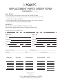
1
SERENITY SERIES Owner’s Manual & Installation Guide Note: Read all instructions before proceeding with installation. All specifications are ± 1/4’’ and are subject to change without notice. Aquatic 1 TABLE OF CONTENTS Product Registration information Congratulations! Safety Instructions Installation Instructions Pre-Installation Procedures Structural Preparation Factory Installed Tile Flange Plumbing Rough-In Measurements Electrical Installation Chromatherapy LED Lighting Variable Speed Air Blower Remote Mounting Installation Instructions for Freestanding Models Variable Speed Air Blower Remote Mounting for Freestanding Models Serenity 27 Installation and Maintenance Instructions 2 3 4 5 6 7 8 9 10 11 12 13 14 17 20 Operation Electronic Control Panel Purge Cycle Automated Dry Cycle Purge 24 Hours Remote Control Operation 23 23 23 24 24 Maintenance and Care Cleaning Flushing/Sanitizing Surface Scratch Removal Repair FCC Information Serial Number - How to Locate 26 26 26 26 27 27 Troubleshooting guide Symptoms/Possible Problems/Solutions 28 parts order form/parts map/parts list Parts Map Parts List Replacement Parts Order Form 28 29 30 aquatic limited warranty 31 Aquatic Aquatic Product Registration Information Your product warranty is registered and confirmed with Aquatic through the Serial Number on your unit. You do not need to contact Aquatic to confirm registration. Please fill out the information below and reference when contacting the distributor to expedite warranty claims. Owner Information: Model Name Serial Number (See Table of Contents for Location) Purchase Date Distributor 8101 E. Kaiser Blvd. • Anaheim, CA 92808 (800) 877-2005 • Fax (714) 998-5340 www.aquaticbath.com Aquatic 3 congratulations! You have chosen one of the finest bath products in the world! Aquatic supports your purchase with strong commitments to quality and customer satisfaction. Please read and follow all of the instructions contained in this Owner’s Manual before installing, operating or maintaining your air bath. In addition, you should continually refer to these instructions during the life of your air bath. Failure to comply with these instructions may invalidate your warranty. If you have any questions concerning installation, operation, maintenance or any other aspect of your air bath, please contact: Aquatic CUSTOMER SERVICE CENTER: 800-945-2726 (The Troubleshooting Guide on page 28 may be helpful in answering some of your questions.) NOTE: The installation and service of your air bath should be performed ONLY by a qualified electrician, technician or plumber. Important! This product must be water-tested and inspected prior to installation or warranty will be voided. See page 6 for instructions. PLEASE CHECK ENTIRE UNIT FOR any DAMAGE. If it appears damaged, contact your Aquatic Distributor immediately. Aquatic warranty does not cover damage that occurs in transit. 4 Aquatic IMPORTANT SAFETY INSTRUCTIONS warning: when using this unit, these basic precautions should be followed. This manual contains information and instructions for proper operation and maintenance of your air bath. Failure to follow these instructions could result in personal injury, electrical shock or fire. READ AND FOLLOW ALL INSTRUCTIONS danger! To reduce the risk of injury: 1. Do not permit children to use this unit unless they are closely supervised by an adult at all times. Supervision is also required when air bath is used by an elderly or handicapped individual. 2. Use this unit only for its intended use as described in this manual. Do not use attachments not recommended by the manufacturer. 3. The water in an air bath should never exceed 40°C (104°F). Water temperatures between 38°C (100°F) and 40°C (104°F) are considered safe for a healthy adult. Use time should be limited to approximately 30 minutes, followed by a shower to cool down. Longer exposures may result in hyperthermia. The symptoms of this condition are nausea, dizziness and fainting, which can be fatal. Lower water temperatures are recommended for extended use (exceeding 10-15 minutes) and for young children. 4. Since excessive water temperatures have a high potential for causing fetal damage during the early months of pregnancy, pregnant or possibly pregnant women should limit air bath water temperatures to 38°C (100°F). 5. The use of drugs or alcoholic beverages before or during air bath use may lead to unconsciousness with the possibility of drowning. Never use the air bath while under the influence of alcohol, anticoagulants, stimulants, antihistamines, vasoconstrictors, vasodilators, hypnotics, narcotics or tranquilizers. 6. Persons with a medical history of heart disease, low or high blood pressure, circulatory system problems, or diabetes should consult a physician before using an air bath. 7. Persons using medication should consult a physician before using an air bath since medication may induce drowsiness while other medication may affect heart rate, blood pressure and circulation. danger: To reduce the risk of injury, enter and exit the bath slowly. Warning: Never operate electrical devices in or near the bath. Never drop or insert any object into any opening within the air bath. This unit must be connected to a supply circuit that is protected by a Ground Fault Circuit Interrupter (GFCI). Such a device should be installed by a licensed electrician and should be tested on a regular basis (at least monthly). To test the GFCI push the TEST button. The GFCI should interrupt the power. Push the RESET button and the power should be restored. If the GFCI fails to operate in this manner there is the possibility of an electric shock. DO NOT USE. Disconnect the unit and have the problem corrected by a qualified service technician. To avoid the possibility of personal injury and discoloration of the acrylic surface, the inlet water temperature should not exceed 60°C (140°F). The bath should be drained after each use. Each bather should start their bath with fresh water. caution: do not use harsh abrasives or solvents for cleaning this unit. installer/owner bears all responsibility to comply with all state and local codes when installing this product. SAVE THESE INSTRUCTIONS Aquatic 5 INSTALLATION INSTRUCTION GUIDELINES READ ALL INSTRUCTIONS CAREFULLY BEFORE INSTALLATION PRE-INSTALLATION PROCEDURES: please note: the manufacturer accepts a 1/4” variance. there are variations on each tub and specifications are subject to change as we improve upon our product as required. the dimensions needed for site preparation and structure buildings should be measured from the tub; Aquatic assumes no responsibility for preparatory work. Note: A good knowledge of construction techniques, plumbing and electrical installation according to codes are required for proper installation. We recommend that a qualified licensed contractor perform the installation of all Aquatic products. Our warranty does not cover improper installation problems. 1. Immediately upon receiving your Aquatic air bath, inspect it thoroughly for freight damage. If necessary, contact your distributor immediately (your distributor must contact Aquatic within 24 hours of receiving unit to file a claim). Should inspection indicate any damage, do not install the bath. 2. All baths are filled with water and operated in our manufacturing facility prior to shipment. Inspectors ensure watertight operation, however, rough handling may cause leaks which may be detected prior to installation. Damage or defect to the finish claimed after the bath is installed is not covered under the warranty. To inspect: 1. Place the tub in an area where it may be drained after testing. 2. Fill the tub with hot water (approximately 1000 F) to the overflow and allow to stand for a few minutes. Carefully inspect all fittings and connections for leaks. 3. Plug in blower control box and run blower for 10 minutes. 4. Inspect the tub completely. Any defect must be reported to Aquatic prior to installation in order to have it covered by warranty. Should inspection indicate any damage or leaks, do not install the bath. 5. Check to ensure that your installation will conform to all applicable codes and secure necessary permits. All electrical and plumbing connections should be made by qualified electricians and plumbers. Damage or leaks claimed after the bath is installed are not covered under the warranty. warning: failure to follow these instructions during installation will result in termination of the warranty: Do not lift the tub by any portion of the plumbing or blower. Do not stand in the tub during construction. DO NOT MAKE ANY ALTERATIONS, ADDITIONS, OR DELETIONS TO THE air bath SYSTEM blower or bath. SERENITY FREESTANDING MODELS PARTS LIST: The following parts are included with the freestanding models. Please contact Aquatic if any parts are missing: 1. 1- 1 1/2” Union Check Valve - 8427FTG attached to 1- Blower - 8000BLW 2. 1- Control Box - 8075BOX 3. 1- Remote Control (batteries installed) - 1013 4. 1- Infrared Sensor attached to 25 foot cable - 1014 5. 1- Key Pad (without chromatherapy button) - 8079BPADxx (prior to 2008) or 1113PADCL (2008 and later) 6. 1- Key Pad Cable - 25 feet - 1050 7. 1- Pipe Cover Tube (see below for finish part numbers): (For Serenity 10 and 37 only) 1035 - Chrome 1036 - Polished Brass 1037 - Satin Nickel 1038 - Polished Nickel 1039 - White 1038ORB - Oil Rubbed Bronze 6 Aquatic INSTALLATION INSTRUCTION GUIDELINES READ ALL INSTRUCTIONS CAREFULLY BEFORE INSTALLATION QUIETNESS OF OPERATION: Aquatic has engineered their air baths from base to lip to ensure quality, value, functional design, and maximum bathing comfort. However, installation is accountable for as much as 50% of a tub’s operating quietness. Please ensure the following: • The floor structure is adequate to support the installation. • For quieter operation and heat retention conservation, the walls surrounding the air bath may be insulated.* • Insulate the tub surround.* Do not allow any insulation to come within 3 feet of the blower. The area around the blower must be clean and free of any foreign matter. • Leave 1/8” to 3/16” gap between tub lip and surround.* • Spread a bed of cement mortar on the floor or subfloor under the air bath to reduce vibration and noise.* *Not required on freestanding models. See pages 14-21 for additional installation instructions for freestanding models. STRUCTURAL PREPARATION: Note: The bath should remain in its shipping carton until time of installation. 1. Literature dimensions are for reference only. Installation dimensions should be taken directly from the tub. An unobstructed access panel of 16” x 16” minimum must be provided at the blower end of the air bath allowing sufficient clearance to make final connections and for servicing the blower and power panel. Access may be through the wall or platform apron at the end of the unit. In the case of sunken installations, access should be made through the ceiling below. A minimum ventilation opening of 2” x 4” for the blower is required and should be designed to draw in ambient air at a minimum of 72° F. It is the installer’s responsibility to provide sufficient service access. Make absolutely certain that access panels and/or service openings are properly placed and that all possible areas where service may be required are accessible. 2. Install the drain fitting to the bath. The Drain Fitting will protrude below the base of the tub approximately 1 1/2”. Clearance may be needed for the drain by cutting away the subfloor (where possible) or by blocking below the tub as may be required. WARNING: FACTORY SKIRTS DO NOT ALLOW FOR BLOCKING UP OF THE TUB BASE. All blocking must be solid and provide uniform support to the tub base. Note: Watertight installation of the drain and overflow is the installer’s responsibility. Drain and/or overflow leakage is not included in the warranty of this product. 3. Tub must rest entirely on its base. Do not support the base of the tub by the rim. Aquatic strongly recommends preparing a bed of wet mortar in the area where tub is to be installed to assist in leveling and reduce vibration noise. Carefully level unit, ensuring that uniform support is given to all areas of the base and no portion of the lip is bearing weight. 4. Frame out under the tub rim as shown in one of the illustrations below. NOTE: Due to the variety of installations possible, framing procedures other than those described may be required. Level in selected location. Level front to back and across both sides. A ledge under the rim, or an apron without a ledge, may be constructed as required (see Diagrams 1A and 1B on page 8). Where installation will be against a wall, stud wall framing should allow for wall sheathing material to run full length to the floor (see Diagram 1C on page 8). Install tub firmly against sheathing as indicated, with blocking below rim to prevent deflection or movement of tub. To prevent a rocking movement of tub after installation, it is important to have rim in contact, but not supported by blocking material. Aquatic 7 INSTALLATION INSTRUCTIONS STRUCTURAL PREPARATION: 5. When placing the tub on a platform or cut out (see Diagrams 1A and 1D), the opening should be 1” smaller than the specified rim dimensions. Extreme care must be taken in this type of installation to ensure the tub will come to rest entirely on the base. 1A 1B 1C 1D *Does not apply to freestanding models. WARNING: ALL ELECTRICAL CONNECTIONS SHOULD BE MADE BY A LOCALLY LICENSED ELECTRICIAN. 6. Another installation option is that of a tile flange. Aquatic offers an optional factory installed tile flange for all rectangular and corner-unit air baths. Factory installed tile flange: 1. Install the air bath unit per the instructions provided in this manual. CAUTION: THE TILE FLANGE DOES NOT SUPPORT THE TUB! A ledger board must be provided under the bath rim as indicated in the installation instructions. Take care to ensure tub is not hanging from the ledger boards, as this will void your warranty. 2. Use nails or screws to secure the flange into the studs around the bath. 3. Install water resistant drywall against the tile flange and flush to the top of the air bath deck. Install the tile or other finishing materials. Apply a second bead of silicone between the first course of tile and the bath deck. 2A NOTE: Before tub is used, the air bath system should be cleaned in accordance with the procedures on Page 26 of this manual. 8 Aquatic INSTALLATION INSTRUCTIONS plumbing: 1. After securing tub in place, normal waste and overflow, water spout and valves are installed per normal plumbing procedures, in accordance with all state and local standards. 2. Install standard 1-1/2” trap to drain and overflow. Before proceeding, make final operational check by filling tub with water to overflow and operate blower for 5 minutes. Carefully check for leaks both while blower is running and after it has been turned off. Allow water to stand in tub for at least 30 minutes before draining. Aquatic will not be responsible for water damage of any kind. 3. When selecting fill spout location, check to ensure that spout is long enough to clear the tub rim from its desired location. If installation is to be on the tub deck, check the back side of tub for adequate space for connection to water lines and that there are no air channels running under that area of the tub rim before drilling or cutting tub. 4. A service access panel of a minimum of a 16” square must be provided adjacent to blower and control box assembly. Aquatic 9 INSTALLATION INSTRUCTIONS Rough-In Measurements: MODEL A From center of overflow pipe to outside rim B A 6A From center of drain to tub rim Serenity 1 6 1/4" 13" Serenity 2 5 3/4" 13 1/4" Serenity 3 1 1/2" 10 1/2" Serenity 4 1 1/2" 10 1/4" Serenity 5 1 3/4" 10" Serenity 6 5 1/2" 14 1/4" Serenity 7 2 1/4" 9 3/4" Serenity Studio 8 2 1/2" 14" Serenity Studio 9 2 1/2" 13" Serenity 10 4 3/4" 12 1/8" Serenity 11 4 3/4" 12 1/8" Serenity Studio 12 4 3/4" 12 1/8" Serenity 13 3 1/2" 11" Serenity 14 2 1/2" 15 1/2" Serenity 15 2 1/2" 9 1/2" Serenity 16 5 3/8" 12" Serenity Studio 17 4 3/4" 12 1/8" Serenity Studio 18 3 1/2" 12 1/2" Serenity Studio 19 3 1/2" 10 3/4" Serenity Studio 20 4 3/4" 12 1/8" Serenity Studio 21 2 1/4" 12 1/4" Serenity Studio 22 2 1/4" 10 1/2" Serenity Studio 23 3 1/2" 12 1/2" Serenity Studio 24 2 3/4" 10 1/2" Serenity Studio 25 3 1/4" 12" Serenity Studio 26 10 B 2" 10" Serenity 27 1 3/4" 11 1/4" Serenity 28 Motif 3 1/2" 12 1/4" Serenity 29 Motif 5 1/2" 13 1/2" Serenity 30 Motif 3 1/2" 12 1/2" Serenity 31 Motif 5 1/2" 13 1/2" Serenity 32 Motif 6" 14" Serenity 33 1 1/2" 8 3/4" Serenity Studio 34 2 3/4" 10 3/4" Serenity Studio 35 2 3/4" 10 3/4" Serenity Studio 36 3" 10 1/2" Serenity 37 3 1/2" 11" Serenity 40 1 3/4" 11 1/2" Serenity 41 1 1/2" 11 1/2" Serenity 42 1 1/2" 11 1/2" Aquatic INSTALLATION INSTRUCTIONS electrical installation: WARNING: ALL ELECTRICAL CONNECTIONS SHOULD BE MADE BY A LICENSED, LOCALLY CERTIFIED ELECTRICIAN, IN ACCORDANCE WITH THE REQUIREMENTS OF THE NATIONAL ELECTRICAL CODES AND PROCEDURES. WARNING: When using electrical products, precautions should always be followed, including the following: DANGER: RISK OF ELECTRIC SHOCK! This unit requires one dedicated circuit, protected by a Ground Fault Circuit Interrupter (GFCI). Rough in wiring to control box on a dedicated 120V, 15 amp, GFCI protected circuit. GFCI’s are not supplied, however we do specify their use. All known code authorities require GFCIs. ELECTRICAL: The blower is prewired to a control box on a cord. A GFCI protected, 120 Volt, 15 Amp, 60 HZ circuit with a service ground is required, “dedicated” only to powering the bath. Please Note: Because the blower is housed in a plastic non-conductive housing, the Blower does not need to be grounded. Danger: Risk of electric shock. Do not alter the factory installed wiring. A licensed electrician must provide the “dedicated” electrical service protected by a GFCI. The location of the GFCI must be accessible for regular testing. USE COPPER CONDUCTORS ONLY. CAUTION: Before use of the blower, test the GFCI for proper operation. The blower should turn off when the GFCI “Test” button is pushed. Warning: Prolonged Immersions in Hotter Water May Induce Hyperthermia. Hyperthermia occurs when the internal temperature of the body reaches a level several degrees above the normal body temperature of 98.6o F. The symptoms of hyperthermia include an increase in the internal temperature of the body, dizziness, lethargy, drowsiness, and fainting. The effects of hyperthermia include (1) failure to perceive heat, (2) failure to recognize the need to exit the air bath, (3) unawareness of impending hazard, (4) fetal damage in pregnant women, (5) physical inability to exit the air bath, (6) unconsciousness resulting in the danger of drowning. WARNING: The use of alcohol, drugs, or medication can greatly increase the risk of fatal hyperthermia. Aquatic 11 INSTALLATION INSTRUCTIONS Chromatherapy LED lighting: All Serenity models* come equipped with a digital color-changing underwater light for soothing chromatherapy. To complement your bathing experience, the Aquatic electronic control panel allows you to select a color according to the desired effects. To Turn Your Chromatherapy Lighting System ON: Press the light button once to turn the Chromatherapy Light on in color wash mode. A second press of the button will turn the lighting system off. Subsequent presses will move the lighting system through the seven constant color modes. • 1st Press Color Wash: Random color blend • 2nd Press Off • 3rd Press White: Clarity • 4th Press Off • 5th Press Aqua: Calm • 6th Press Off • 7th Press Violet: Inspiration • 8th Press Off • 9th Press Blue: Peace • 10th Press Off • 11th Press Yellow: Hope • 12th Press Off • 13th Press Green: Harmony • 14th Press Off • 15th Press Red: Courage To Replace Bulb: 1. Disconnect the power to your bathtub. 2. Drain the bathtub. 3. Open the lens of the fixture using ONLY the proper tool provided for that purpose (see Diagram 7A). Do not attempt to remove the lens without the provided tool. 4. Replace your LED light (replacement LED lights can be obtained from Aquatic). 5. Verify “O” ring is not damaged and is properly positioned in the groove when replacing the lens. If there is damage or lens does not seal properly, do not refill bathtub. troubleshooting guide for Underwater mood Light: NOTE: Do not twist LED light into socket. Use gentle pressure and push LED light into place. Bath Surface 7A *Does not apply to freestanding models. 12 Aquatic INSTALLATION INSTRUCTIONS Variable Speed Air Blower Remote mounting All models except freestanding models Relocating the Variable Speed Air Blower: All electrical connections should be done by a licensed electrician. The blower and controls are installed at the factory. If you wish to install the blower for a more convenient access, please follow the instructions provided below. Blower Check Valve Designating a Remote Location: The designated location for the blower must not require more than 15 feet of pipe and 6 directional changes. Choose a place as close to the bath as possible to make sure that the system works properly. The chosen place must not be cluttered and/or dusty and must allow for sufficient air circulation. The blower measures 6” W x 10” L x 6” H. The blower control box measures 4” W x 4” L x 3” H. This space must not be smaller than 4 cubic feet and must have a ventilation opening not smaller than 2” x 4”. The air around the blower should be approximately 72°F (20°C) or higher for optimal performance. Blower 8A Screw Screws (4) -- hold blower to base • The blower and control box must be accessible at all times. • The extension cords must be able to reach the control box and be routed per local code requirements. Removing Components from the Base: 1. Disconnect the key pad cable from the control box, and then add the extension cable. 2. Disconnect the blower cable from the control box. 3. Disconnect the chromatherapy light wiring from the connectors at the control box, and then add the extension cable. Be careful when disconnecting the chromatherapy LED light connectors. Hold the connectors, not the wires, so that the wires do not pull out of the connectors. 4. Disconnect the water sensor wires from the control box, then add the extension cord. 5. Remove the screw attaching the PVC pipe to the blower. 6. Remove the blower and control box from the ABS support base. Installing the Blower in a Remote Location: The blower can be installed horizontally or vertically. The blower intake maybe installed up or down. Use PVC 1 1/2” pipe and adapters only. Whenever possible, use two 45° elbows instead of one 90° elbow to change the direction of your pipe. Glue all pipe connections along the extension you have added. But DO NOT glue the pipe going into the blower; use the screw you removed when the blower was removed. • • The blower should be 6” off the floor or from the ceiling and the air intake end of the blower should be at least 4” from any walls or joists. To reduce heat loss, insulate the pipe. Mount the Control Box close to the blower and the AC outlet. Plug in the key pad cable, blower cable, water level sensor cable and attach the Chromatherapy LED light wires. (See Diagram 8B) Now plug into a minimum 15 amp, 110 vac that is GFCI protected. Remote Installation in adjacent space (closet) (example only) 4’’ Blower AC Outlet To: 110 vac minimum 15 amp dedicated GFCI protected circuit Low Voltage Cord to Keypad Check Valve To Blower Chromatherapy LED Light Water Sensor Wires (Black and Red) Located by Drain 6’’ 8B Chromatherapy LED Light - 2 Wires Control Box To Key Pad Aquatic To IR Sensor (Not Used) Water Level Sensor (Not on freestanding models) 13 INSTALLATION INSTRUCTIONS installation of freestanding models: 9A NOTE: • Freestanding units must be placed on a perfectly leveled floor. • The blower must be mounted in a remote location and • cannot be installed on the bath (see pages 17 and 18). Wall mounted or freestanding faucets must be used. 22 1/2” Serenity 10 & 37 Installation: For information on electrical installation, maintenance and care, troubleshooting and warranty, please refer to the Table of Contents. 17 1/4” SERENITY 10 BOTTOM VIEW Blower Fitting Before the floor installation is complete, make sure it is perfectly level. Once the floor installation is complete, determine the exact location of the bath and mark the floor position of the four claw feet (see Diagram 9A). The bath must be anchored to the floor. Also, mark the position of the holes to be drilled for the blower air passage and drain. 20 1/4” 1. Drill four holes for the feet. Then drill a 2” hole for the air passage and 2” hole for the drain. 16 1/2” 2. Install the drain and overflow on the bath. Cut pipes to desired length prior to assembly. Next, glue the first section of pipe (PVC 1 1/2”) to the air passage under the tub and then cover the pipe with the pipe concealer (see Diagram 9B). SERENITY 37 BOTTOM VIEW Blower Fitting 3. Once the pipe has been installed through the floor and the bath has been placed, secure the four feet with 1/4” lag bolts or concrete anchors (see Diagram 9C). 9B 14 Pipe Concealer 9C Cut pipes to desired length prior to assembly Aquatic INSTALLATION INSTRUCTIONS Serenity 11 & 13 Installation: Anchor Pin Holes 10A Before the floor installation is complete, make sure the floor is level. Once the floor installation is complete, determine the exact location of the bath and trace the contour of the bath with an erasable marker pen. For information on electrical installation, maintenance and care, troubleshooting and warranty, please refer to the Table of Contents. 20” 20 1/2” 17 1/4” 1. Determine the exact location of the drain, air passage and the two anchoring points at each end of the bath (see Diagram 10A for Serenity 11 and 13). 2. Drill 2” holes for the drain and air passage holes. To prevent the bath from moving sideways, secure the two anchoring pins (3/8” x 3” lag bolts) to the floor. Leave the lag bolts 1 1/2” above floor. Wipe off the marker tracings (see Diagram 10D). 20” 22 1/2” SERENITY 11 BOTTOM VIEW Blower Fitting Anchor Pin Holes 3. Install the overflow and drain on the bath. Cut pipes to desired length prior to assembly. Glue the first pipe section (PVC 1 1/2”) of the air passage to go under the floor and make sure pins are lined up with holes in tub. Apply a silicone seal under the rim of the base and lay the bath down putting the pipes through the floor. Immediately remove any excess silicone (see Diagrams 10B and 10C). 20” 17” 10A 20” 20 1/4” 16 1/2” SERENITY 13 BOTTOM VIEW Blower Fitting Cut pipes to desired length prior to assembly 10B 10C 10D 10D Anchor Pins Anchor Pins 20” 20 1/2” 20” SERENITY 11 SIDE VIEW Aquatic 20” 17” 20” SERENITY 13 SIDE VIEW 15 INSTALLATION INSTRUCTIONS Serenity STUDIO 17, 23, 24, 25 and 26 Installation: Before the floor installation is complete, make sure the floor is level. Once the floor installation is complete, determine the exact location of the bath and trace the contour of the bath with an erasable marker pen. For information on electrical installation, maintenance and care, troubleshooting and warranty, please refer to the Table of Contents. 1. Determine the exact location of the drain, air passage and the two anchoring points at each end of the bath (see following diagrams). 21 3/8” Blower Fitting Serenity Studio 17 BLOWER FITTING BLOWER FITTING Serenity Studio 24 Serenity Studio 23 BLOWER FITTING BLOWER FITTING Serenity Studio 25 16 Bottom View Serenity Studio 26 Aquatic INSTALLATION INSTRUCTIONS Serenity STUDIO 17, 23, 24, 25 and 26 Installation (Cont): 2. Drill 2” holes for the drain and air passage holes. To prevent the bath from moving sideways, secure the two anchoring pins (3/8” x 3” lag bolts) to the floor (see Diagram 10F). Leave the lag bolts 1 1/2” above floor. Wipe off the marker tracings. 10G 3. Install the overflow and drain on the bath. Cut pipes to desired length prior to assembly (see Diagram 10G). Glue the first pipe section (PVC 1 1/2”) of the air passage to go under the floor and make sure pins are lined up with holes in tub. Apply a silicone seal under the rim of the base and lay the bath down putting the pipes through the floor. Immediately remove any excess silicone. 10F Variable speed air blower remote mounting for freestanding models: Designating a Remote Location: The designated location for the blower must not require more than 15 feet of pipe and 6 directional changes. Choose a place as close to the bath as possible to make sure that the system works properly. The chosen place must not be cluttered and/or dusty and must allow for sufficient air circulation. The air around the blower should be approximately 72°F (20°C) for optimal performance. The blower and control box must be accessible at all times. See pages 18-19 for installation diagrams. Installing the Blower in a Remote Location: The blower will come attached to the one way check valve, make sure the arrow on the valve is pointing away from the blower. The blower can be installed horizontally or vertically. The blower intake may be installed up or down. Use PVC 1½” pipe and adapters only. Whenever possible, use two 45° elbows instead of one 90° elbow to change the direction of your pipe. Glue all pipe connections along the extension you have added. The blower should be 6” off the floor or ceiling and the air intake end of the blower should be at least 4” from any walls or joists. The location of the blower should not be air tight; a gap of 1” is recommended for good air circulation. To reduce heat loss, insulate the pipe. Mounting the Control Box: Mount the control box close to the blower and the AC outlet. (120 vac minimum 15 amp dedicated GFCI protected). You will be able to mount both the infrared sensor and key pad (attach by pressure sensitive tape on back of keypad) or you may want to mount only the Infrared Sensor. When mounting the infrared sensor be sure there are no obstructions between the sensor and the tub. Both cables are 25 feet long. At the control box, plug the cord from the blower into the control box, then plug in the infrared sensor cord and the key pad cord, if it is going to be used. Then plug in the three prong plug to a 120 vac minimum 15 amp dedicated GFCI protected outlet. See control box wiring diagrams on pages 18, 19 and 21. Aim remote control at the infrared sensor and check. (See Remote Control Operation on pages 24-25.) Note: A red light will flash rapidly after pushing any button on the remote control. If light does not flash when a key is depressed, replace the batteries. Aquatic 17 INSTALLATION INSTRUCTIONS Serenity 10 & 37 Key Pad Infrared Sensor Flow Blower Control Box One Way Valve Serenity Freestanding model Control Box Wiring To 120 vac minimum 15 amp dedicated GFCI protected circuit To Blower To Key Pad Control Box To IR Sensor Not Used Not Used Key Pad Infrared Sensor Flow Blower 18 One Way Valve Aquatic INSTALLATION INSTRUCTIONS Serenity 11, 13, 17, 23, 24, 25 and 26 Key Pad Infrared Sensor Flow Blower Control Box One Way Valve Serenity freestanding model Control Box Wiring To 120 vac minimum 15 amp dedicated GFCI protected circuit To Blower To Key Pad Control Box To IR Sensor Not Used Not Used Key Pad Infrared Sensor Flow Blower Aquatic One Way Valve 19 INSTALLATION INSTRUCTIONS Serenity 27 Copper Air Bath Serenity STUDIO 27 Installation: Before the floor installation is complete, make sure the floor is level. Once the floor installation is complete, determine the exact location of the bath and trace the contour of the bath with an erasable marker pen. BOTTOM VIEW For information on electrical installation, maintenance and care, troubleshooting and warranty, please refer to the Table of Contents. 1.Determine the exact location of the drain, air passage and the two anchoring points at each end of the bath (see diagram at right). Because the Serenity 27 Air Bath is hand-crafted, no two tubs are alike and measurements for anchoring points will vary. Anchoring Pin Locations 2.Drill 2” holes for the drain and air passage holes. To prevent the bath from moving sideways, secure the two anchoring pins (3/8” x 3” lag bolts, not supplied). Measure the distance between the center of the anchoring pin holes (see diagram). Install the lag bolts to the floor based on this measurement. Wipe off marker tracings. 3.Install the overflow and drain on the bath. Cut pipes to desired length prior to assembly (see diagram on page 21). Glue the first pipe section (PVC 1 1/2”) of the air passage to go under the floor and make sure pins are lined up. Apply a silicone seal under the rim of the base and lay the bath down putting the pipes through the floor. Immediately remove any excess silicone. 4. Find a location for the Hartford Loop; you can mount the Hartford Loop inside a wall or on a wall in an adjacent room. 5. The top 2 inches of the Hartford Loop must be above the bottom of the over flow hole. (See diagram) 6. Under the tub will be a one way check valve. Attach PVC pipe to this valve and run the pipe under or in the floor to one end of the Hartford Loop. 7. Attach the other end to the one way check valve attached to the blower. Both check valves will have an arrow indicating air flow. Make sure the arrows point towards the tub. 8.If the blower will be installed in an enclosure, you must provide a minimum 4”x 4” opening for ventilation. NOTE: Because the Serenity 27 is a one-of-a-kind bath, dimensions may vary up to several inches. Please take all measurements directly from the bath. 20 Aquatic INSTALLATION INSTRUCTIONS Serenity 27 Copper Air Bath The Hartford loop can be installed in or on a wall (see directions) anchored to a 2x4. Install so that two inches of loop is above the bottom of the overflow hole. Key Pad Infrared Sensor 2” Overflow Hole Hartford Loop One Way Valve is Under Tub Flow Control Box Blower One Way Valve Serenity freestanding model control Box Wiring To 120 vac minimum 15 amp dedicated GFCI protected circuit To Blower To Key Pad Key Pad Infrared Sensor To IR Sensor Not Used Not Used Hartford Loop 2” Overflow Hole One Way Valve is Under Tub Control Box Flow Blower One Way Valve Aquatic 21 MAINTENANCE and care Serenity 27 Copper Air Bath CLEANING: · · · · · · · · Wash with soap that has low acidic content (anything with acid will act as a polisher), water, and a NON ABRASIVE cloth or sponge. NEVER USE anything abrasive, such as Soft Scrub, Clorox or Drano type products. DO NOT use a copper polish. You will ruin the tub’s finish. DO NOT use Flitz Faucet and Fixture Wax. This product will ruin the finish. It is highly recommended that you use a car wax to protect the finish on the exterior of the tub. Re-wax exterior of tub when needed. DO NOT wax the interior of the tub. This finish needs to be treated with extra care. flushing / sanitizing: Before tub is used, your air bath and plumbing system should be flushed. Close the drain. Fill bath with hot water to at least six inches above air injector holes. Add two teaspoons of low sudsing automatic dishwashing detergent. DO NOT use bleach or other chlorinated cleansers on metal surfaces. Turn bath on for approximately two minutes to mix cleaner with water. Shut blower down and allow cleaner to soak in the bath for approximately two hours. Turn on air bath and run for approximately five minutes. Turn air bath unit off and drain tub. Aquatic recommends the above cleaning process on your air bath once a month. The installation and service of your air bath should be performed only by a qualified service technician. Remember when contacting your distributor always have your serial number, proof of purchase and model number available. This will ensure a quick response on warranty items. See page 27 for serial number location. note: all warranty repairs must be authorized by aquatic before work is started. for service, always contact your DISTRIBUTOR or authorized service center. WATER AND AIR TEMPERATURE: Each Serenity model is equipped with a 600 watt air heating system to raise the temperature of the air going into the bath. This air temperature will be less than the bathing temperature of the water, but will help to reduce a rapid decrease in water temperature. In addition, the air coming from the air jets will feel cool against the skin, just as a breeze on a warm day cools your body. This system does not heat the water. 22 Aquatic operation of SERENITY AIR BATHS BATHside CONTROL SYSTEMS: Electronic Control Panel (see Diagram 11A): 1. To Turn Air Bath System On: Pressing the on/off button will turn the blower on in “constant mode.” The light indicator will illuminate when the system is on. The blower and the heater will automatically shut off after a 20-minute period. 2. To Change Modes: Pressing the mode button alternates the blower modes of operation from constant mode to wave mode and then to pulse mode. • Constant Mode: Consists of a constant blower level with no change. When the blower is on, the indicator light is on. When the blower is off, the indicator light is off. On/Off Button Indicator Light Mode Key Decrease Speed Increase Speed Chromatherapy Light (not included on freestanding models) 11A • Wave Mode: Consists of a gradual change of blower level to generate a gentle massage effect. The light indicator will also follow the blower intensity. • Pulse Mode: Consists of an instant change of the blower level to generate a massage effect. The light indicator will also pulse as the blower does. 3. To Change Speeds: In constant mode, pressing and holding the “+” button will increase the variable speed of the blower to the maximum. Pressing and holding the “—” button will reduce the blower’s variable speed to the minimum. In both cases, the user can release the button at the desired power level. Note: In wave mode or pulse mode, the “+” or “—” buttons will work the same way but will have an effect on the maximum power of the wave and pulse mode. 4. To Turn Chromatherapy Light On: Press the light button once to turn the Chromatherapy Light on in color wash mode. A second press of the button will turn the lighting system off. Subsequent presses will move the lighting system through the seven constant color modes. CAUTION: Due to the varied size, weight and shape of a person’s body, water may splash out of the tub when the air blower is on high speed. Turn the speed of the blower down using the minus button to a lower setting to reduce the amount of water being dispersed from the tub. NOTE: THE CONTROL PANEL ON THE FREESTANDING MODELS DOES NOT INCLUDE A CHROMATHERAPY LIGHT BUTTON. Air Bath Purge Cycle: Following the 20 minute run time of the blower, there will be a 15 minute idle period. The blower will then turn on for 3 minutes for the purge cycle. If the user turns the blower off manually before the timer reaches 20 minutes, the idle period will start after the blower has been turned off. During the 15 minute idle period and the 3 minutes purge, the light indicator of the on/off button will blink. During the idle period, pressing the on/off button will turn on the blower in constant mode. During the 3 minute purge, pressing the blower key will stop the purge. Automated dry Cycle: Regardless if the air bath system was utilized, an automated dry cycle will turn on 20 minutes after the water sensors do not detect water. The automated dry cycle will turn on for 3 minutes (once the sensors are dry) to purge the air channels after any contact with water, including after a shower or cleaning/rinsing of the bath. The two water sensors are located near the drain. Not included on freestanding models. Aquatic 23 operation of SERENITY AIR BATHS Purge 24 Hours: It is possible for the user to program a purge cycle that will start every day for a duration of 1 minute. Aquatic strongly recommends activating this feature. The purge cycle will help ensure that the air channels stay dry even when you have taken a soaking bath or shower. To activate this purge feature, the user must hold down the “+” button for 5 seconds when the blower/heater is off or waiting for the normal purge. Then, the light indicator on the on/off button will blink twice. If the unit was in standby for a normal purge when the 24 hour purge was activated, the normal purge will be cancelled. To show the user that the 24 hour purge is activated, the light indicator on the on/off button will blink at a slow rate. A different blinking rate was picked in order to make it easier for the user to differentiate it from the standby of the regular purge cycle. The purge will be done every day at the same time the user activated it (pressed the “+” button). By pressing the “+” button again, the 24 hour purge will be deactivated and the light indicator on the on/off button will stop blinking and turn off. remote control operation: 12A Blower On/Off Blower Mode LED Increase Blower Speed Decrease Blower Speed chromatherapy Light The Serenity Air Bath System provides a variable speed controlled heated air blower with three massage modes: continuous mode, wave mode with gradually varying blower intensities, and a pulse mode with the blower’s speed changing rapidly from its minimum speed to a user defined maximum speed. The Chromatherapy LED light is also controlled from the remote control (chromatherapy light is not available on freestanding models). A built-in timer shuts the blower off 20 minutes after it has been activated. To dry the plumbing system, an automatic purge cycle will restart the blower for three minutes, 15 minutes after the air bath has been turned off. 24 Aquatic operation of SERENITY AIR BATHS remote control operation: To Turn Air Bath On: Pressing the on/off button will turn the blower on in “constant mode”. Once the blower is on, pressing a second time will turn the blower off. The blower will shut off after a 20-minute period. To Change Modes: Pressing the mode button alternates the blower modes of operation from constant mode to wave mode and then to pulse mode. To Change Speeds: In constant mode, pressing and holding the button will increase the power level of the blower to the maximum speed. Pressing and holding the button will reduce the blower’s power level to the minimum. In both cases, the user can release the button at the desired power level. In wave mode or pulse mode, the or buttons will work the same way, but will have an effect on the maximum power of the wave and pulse mode. To Operate Chromatherapy Light*: Press the light button once to turn the Chromatherapy Light on in color wash mode. A second press of the button will turn the lighting system off. Subsequent presses will move the lighting system through the seven constant color modes. *Chromatherapy Light function is not available on freestanding models. For best results, please remove the remote control from the water when the air bath is not in use. Prolonged exposure to the hot water in your bath may create humidity build-up inside your remote control. This will not affect the operation of the remote, but may alter its appearance. Replacing the Batteries: A red light will flash rapidly after pushing any button on the remote control. If light does not flash when a key is depressed, replace the batteries. The remote control is powered by two AAA batteries. 1. Unscrew and remove bottom cap to remote control. 2. Insert new batteries, making sure to match plus (+) ends with plus markings on the battery case. Refer to the label under your remote. 3. Replace cap ensuring that waterproof gaskets are correctly positioned and cap is well screwed on. Notes: • You can use a coin to unscrew cap. • When replacing batteries, it is recommended to add a lubricant (e.g. Vaseline) on cap gaskets to ensure perfect water tightness. Aquatic 25 MAINTENANCE and care CLEANING: Use common household, non abrasive cleaners for most cleaning jobs. Clean grease, oil, paint and ink stains with Isopropyl (rubbing) alcohol. Rinse well and dry with a clean cloth or sponge. Do not run the air system with foaming cleaners or soaps. Rinse the bath thoroughly after cleaning. Do not allow your Lucite® acrylic surface to come into contact with products such as acetone (nail polish remover), nail polish, dry cleaning solution, lacquer thinners, gasoline, pine oil or other toxic and oily cleaners. flushing / sanitizing: Before tub is used, your air bath and plumbing system should be flushed. Close the drain. Fill bath with hot water to at least six inches above air injector holes. Add 2 teaspoons of low sudsing automatic dishwashing detergent and no more than 4 ounces of bleach to the water. DO NOT use bleach or other chlorinated cleansers on metal trim surrounding control panel. Turn bath on for approximately two minutes to mix cleaner with water. Shut blower down and allow cleaner to soak in the bath for approximately two hours. Turn on air bath and run for approximately five minutes. Turn air bath unit off and drain tub. Aquatic recommends the above cleaning process on your air bath once a month. SURFACE SCRATCH REMOVAL: Minor scratches may be removed by polishing your tub with a non-abrasive car polish, followed by buffing. Deeper scratches can be removed by: • • • • Sanding with wet 400 grit sandpaper. Sanding with wet 600 grit sandpaper. Sanding with wet micro-grit sandpaper. Buff out using car polish. REPAIR: The installation and service of your air bath should be performed only by a qualified service technician. Remember when contacting your distributor always have your serial number, proof of purchase and model number available. This will ensure a quick response on warranty items. See page 27 for serial number location. note: all warranty repairs must be authorized by aquatic before work is started. for service, always contact your DISTRIBUTOR or authorized service center. caution: Care should be taken to prevent inappropriate chemicals coming in contact with the Lucite® acrylic surface. Please read and observe all instructions and/or warnings on containers containing substances you contemplate applying to your air bath. Any failure to comply may void your warranty. WATER AND AIR TEMPERATURE: Each Serenity model is equipped with a 600 watt air heating system to raise the temperature of the air going into the bath. This air temperature will be less than the bathing temperature of the water, but will help to reduce a rapid decrease in water temperature. In addition, the air coming from the air jets will feel cool against the skin, just as a breeze on a warm day cools your body. This system does not heat the water. 26 Aquatic SERENITY AIR BATHS user information Please note: The air bath action may cause even small amounts of bubble bath or shampoo to foam excessively. Exercise moderation in experimenting with different soap products. No servicing of this product should be done by the user. There are no user serviceable parts. All controls are located in the control recesses on the lip of the tub. These are the only controls that should be used by the consumer. Do not change or alter any of these controls under any circumstances. Motors are self-lubricating -- No lubrication required. fcc consumer information Electrical installation information listed on page 11. This equipment generates and uses radio frequency energy and if not installed and used properly, that is, in strict accordance with the manufacturers instruction, may cause interference to radio and television reception. It has been type tested and found to comply with the limits for a class B computing device in accordance with the specifications in subpart J of part 15 of the FCC rules, which are designed to provide reasonable protection against such interference in a residential installation. However, there is no guarantee that interference will not occur in a particular installation. If this equipment does cause interference, which can be determined by turning the equipment on and off, the user is encouraged to try to correct the interference by one or more of the following measures: • • • • Reorient the receiving antenna. Relocate the receiver with respect to the bath tub. Move the receiver away from the bath. Plug the receiver into a different outlet so that the receiver and bath are on different branch circuits. • If necessary, the user should consult the dealer or an experienced radio/television technician for additional suggestions. • The user may find the following booklet prepared by the Federal Communications Commission helpful: “How To Identify and Resolve Radio-TV Interference Problems.” This booklet is available from the U.S. Government Printing Office, Washington, DC 20402, Stock No., 004-000-00345-4. Serial Number Location: The tub model and serial numbers are located above the blower area on the backside of the drop-in models. Your installer should have a service access panel in this location. The numbers are located on the bottom of the tub on freestanding models. Look for a label which resembles the one on the right. Aquatic 27 troubleshooting guide warning: Always turn off power at the main electrical service panel when servicing your air bath. symptoms possible problems suggested solutions Air Bath does not operate. Blower turns off by itself or before time elapses. 1) 2) 3) 4) No power to Air Bath unit. Blower Control Box is not plugged in. Control Panel connector to controller box is disconnected. Blower Motor is disconnected from control box. 1) Reset circuit breakers and GFCI if tripped. Check fuses and replace if bad. 2) Make sure plug is fully inserted into the outlet. 3) Check and reconnect if needed. 4) Plug blower into control box. 1) 2) Blower motor overheated and thermal protection device has deactivated motor (possibly low voltage). GFCI tripped. 1) 2) Check that the blower has sufficient ventilation and that the intake to the blower is not blocked. Clear and allow motor to cool down. (check service and wire size.) Refer to installer/dealer. Circuit breaker trips repeatedly. 1) 2) 3) Defective breaker. Short circuit between bath and breaker box. Other items are connected to the same circuit. 1) 2) Change out breaker. Refer to installer/dealer. 3) Refer to installer/dealer. Blower does not manually shut off. 1) Defective control panel. 2) Defective control box. 1) 2) Refer to installer/dealer. Replace control panel. Refer to installer/dealer. Replace control box. Air Bath does not function properly while in the pulse or wave modes. 1) 1) Change the air speed setting to a mid-range setting before switching to wave or pulse modes. Speed of air setting is set too low. SERENITY AIR BATHS replacement parts Order map 4) and 14) Control panel 5) light wall fitting 1) Air Blower 7) Chromatherapy light 3) Check Valve (one way valve) 28 2) Control Box Aquatic SERENITY AIR BATHS replacement parts list description 1) 2) 3) 4) 5) 6) 7) 8) 9) 10) 11) 12) 13) 14) 15) 16) 17) 18.) 19.) Air Blower Control Box Check Valve Control Panel Light Wall Fitting (incl. socket) Lens Removal Tool (not shown) Chromatherapy LED Light Sculptured Pillow (option) (not shown) Oval Rectangle Lift & Turn Waste and Overflow Cable Drive Waste and Overflow (option) (not shown) Remote Control (option) (not shown) (standard feature on Freestanding Models) Waste and Overflow for Freestanding Serenity Models (option) (not shown) Infrared Sensor attached to 25 foot cable (not shown) (for remote control option) Control Panel (Freestanding Models) (not shown) 25 Foot Cable for Freestanding Models Control Panel (not shown) Pipe Cover Tube (Serenity 10 & 37 only) (not shown) Remote Blower Option Extension for Key Pad Extension for Water Sensors Extension for Light Bolt-On Grab Bar (option) (not shown) Grab Bar Aquatic part number color / finish 8000BLW 8075BOX 8427FTG 8075PADWH 8075PADBR 8075PADCR 8075PADBN 8075PADCL 8075PADORB 1110PADCL (2008 and later models) 8260LIGHT ------ 1055 ---------------White Polished Brass Chrome Satin Nickel Clear Oil Rubbed Bronze --------------------- 9604PILLXX 9601PILLXX 93CPDWO 93PBDWO 93SNDWO 93PNDWO 93PGDWO 93ORBDWO Cable Drive Waste and Overflow 1013 94CPDWO 94WHDWO 94PNDWO 94PBDWO 94SNDWO 94ORBWO 1014 Specify White, Biscuit or Black Specify White, Biscuit or Black Chrome Brass Satin Nickel Polished Nickel Gold Oil Rubbed Bronze Chrome Polished Brass Gold Satin Nickel Polished Nickel Color Matched: Bone, White & Biscuit Only Oil Rubbed Bronze ------ Chrome White Polished Nickel Polished Brass Satin Nickel Oil Rubbed Bronze ------ 8079BPADWH 8079BPADBR 8079BPADCR 8079BPADBN 8079BPADCL 8079BPADORB 1113PADCL (2008 and later models) 1050 White Polished Brass Chrome Satin Nickel Clear Oil Rubbed Bronze ----------- 1035 1036 1037 1038 1039 1038ORB Chrome Polished Brass Satin Nickel Polished Nickel White Oil Rubbed Bronze 1051 1052 1053 901806GRAB 901807GRAB 901800GRAB 901801GRAB 901802GRAB 901803GRAB 901804GRAB 901805GRAB 9017WHGRAB 9017BIGRAB 901710GRAB 901720GRAB 901760GRAB 901770GRAB 901740GRAB 901780GRAB 4174ACROD White Biscuit Chrome Brass Satin Nickel Polished Nickel Gold Oil Rubbed Bronze White Biscuit Chrome Brass Satin Nickel Polished Nickel Gold Oil Rubbed Bronze Clear Acrylic/Specify Model # 29 Replacement parts Order form for Serenity Air Baths How To Use: 1. Find your part on the map and make note of its number and letter. 2. Using map number and letter, choose part number and select color (or finish) on parts list provided on page 29. 3. Fill out the form below with the selected information. Fax or send to Aquatic. 4. Call Aquatic for parts pricing and shipping charges. IMPORTANT! The following information must accompany your order: Serial Number, Model Number/Name, Purchase Date and Color Please fill out completely: SHIP TO: BILL TO: Name Name Company Company Address Address City State Phone Fax City Phone State Zip Fax Zip #)___________________________ Model Name__________________________________ Serial # (Invoice Model #________________________ Color___________________ Purchase Date _____________ Quantity Part No. Description Color/Finish Price Mail orders to: AQUATIC 8101 E. Kaiser Blvd. • Anaheim, CA 92808 (800) 877-2005 • Fax (714) 998-5340 30 Aquatic Aquatic Limited Lifetime Warranty For Millennium, Infinity, Century, LuxeAir, Luxury, Serenity Air Baths, Serenity Studio, HotSoak and Restoration Series Limited Warranty For Original Consumer For Household Usage WHAT PRODUCTS ARE COVERED Structures and surface finishes, pumps and blowers on the Millennium, Infinity, Century, LuxeAir, Luxury, Serenity Air Baths, Serenity Studio, HotSoak, and Restoration Series. Warranty Periods for Specific Components LIFETIME WARRANTY FOR WHIRLPOOL/AIR BATH/TUB SHELL, PUMP AND BLOWER Aquatic extends to the original consumer purchaser of the acrylic, fiberglass reinforced shell, a non-transferable lifetime warranty that the shell will retain its structural integrity and configuration and be free of water loss due to a defect in the tub shell. The warranty covers the tub shell and the factory installed pump and blower against defects in material or workmanship. This warranty does not apply to all other components (attachments to the acrylic, fiberglass reinforced shell, such as plumbing, fittings and other apparatus) because these pieces are covered below under a 2 Year Warranty. LIFETIME SURFACE WARRANTY FOR FACE OF WHIRLPOOL/AIR BATH/TUB The interior surface is warranted against fading, blistering, cracking and delamination due to defects in the surface materials for life. This surface warranty extends to defects due to surface material mixing or molding. This surface warranty does not apply to fading, cracking, delamination or blistering due to excessive wear, sun fading or scouring due to cleaning. 2 YEAR EQUIPMENT WARRANTY FOR SUPPORT EQUIPMENT, COMPONENTS, CONTROLS & PLUMBING EQUIPMENT All support equipment; components, controls and plumbing equipment are warranted for 2 years from date of purchase, but not more than 3 years from date of manufacture, against defects in workmanship and materials. Light bulbs, fuses and pillows are not included in this two-year period. However, these accessories are warranted to be free from defects in materials and workmanship at the time of delivery to the original purchaser. Limited labor is covered for 2 years from purchase, but never more than 3 years from date of manufacture, for limited labor on the support equipment, controls, and plumbing. EXCLUSIVE REMEDY Aquatic will, at its option, repair or replace (without removal or installation) the affected components of any defective Unit or System; repair or replace (without removal or installation) the entire defective Unit or System; or refund the then-current list price of the Whirlpool, Air Bath, or Tub. In all cases, a reasonable time period must be allowed for warranty repairs to be completed. WHAT YOU MUST DO In order to make a claim under these warranties: 1. You must be the original consumer purchaser of the Whirlpool, Air Bath, or Tub. 2. You must promptly notify us within the warranty period of any defect and provide us with any substantiation that we may reasonably request. Write to: Aquatic 1521 No. Cooper, Ste. 500 Arlington, TX 76011. 3. The Whirlpools, Air Baths, and Tubs must have been installed and maintained in accordance with good industry practice and the specific Aquatic directions contained in the Owner’s Manual and Installation Guide. EXCLUSIONS These warranties do not extend to or do not cover defects caused by: 1. Shipping damage by carriers or installation errors. 2. Accident, acts of God, abuse or misuse. 3. Unreasonable use (including any use for non-bathing purposes or failure to provide reasonable and necessary maintenance as specified in Aquatic Owner’s Manual and Installation Guide supplied with the Whirlpool, Air Bath or Tub). 4. Any alteration, customization, or modification of the Whirlpool/Air Bath/Tub or its components. LIMITATIONS 1. Aquatic whirlpools and tubs sold for industrial, commercial and hotel use are warranted for two years, but not more than 3 years from date of manufacture, with a 2 year limited warranty that the shell will retain its structural integrity and configuration and be free of water loss due to a defect in the tub. The interior surface/face of the whirlpool/air bath/tub is warranted against fading, blistering, cracking and delamination due to defects in the surface materials for 2 years as well. All support equipment, components, controls and plumbing equipment and limited labor on the support equipment, controls, or plumbing are warranted for 1 year from date of purchase, but not more than 2 years from date of manufacture. Pump seals, “O” rings, light bulbs, fuses and pillows are not included in this two-year period. However, these accessories are warranted to be free from defects in materials and workmanship at the time of delivery to the original purchaser. 2. In all cases, Aquatic reserves the right to fully satisfy its obligations under the Limited Warranties by refunding the then-current list price of the defective Whirlpool, Air Bath, or Tub (or, if the Whirlpool, Air Bath, or Tub has been discontinued, of the most nearly comparable current product). 3. THESE WARRANTIES ARE NON-TRANSFERABLE TO ANY OTHER PURCHASER OR PARTY OTHER THAN THE ORIGINAL CONSUMER. NO OTHER AGENT OR PARTY CAN GIVE ANY OTHER WARRANTY OR PROMISE. THIS IS THE SOLE WARRANTY FOR YOUR Aquatic PRODUCT. 4. Aquatic will not cover any installation or reinstallation costs related to this warranty, except under the limited labor allowance under the 2 Year Equipment Warranty above. GENERAL This warranty gives you specific legal rights; you may also have other rights, which vary from state to state. THE DURATION OF ANY IMPLIED WARRANTIES, INCLUDING THE IMPLIED WARRANTIES OF MERCHANTABILITY AND FITNESS FOR A PARTICULAR PURPOSE, ARE LIMITED TO THE DURATION OF THE EXPRESS WARRANTIES HEREIN. Aquatic EXPRESSLY EXCLUDES INCIDENTAL AND CONSEQUENTIAL DAMAGES, TO INCLUDE LOSS OF TIME, INCONVENIENCE, OR LOSS OF USE OF RESIDENCE, FOR ANY BREACH OF THE EXPRESS OR IMPLIED WARRANTY, INCLUDING THE IMPLIED WARRANTIES OF MERCHANTABILITY OR FITNESS FOR A PARTICULAR PURPOSE. SOME STATES DO NOT ALLOW ANY LIMITATION ON HOW LONG AN IMPLIED WARRANTY LASTS, OR THE EXCLUSION OR LIMITATION OF INCIDENTAL OR CONSEQUENTIAL DAMAGES; SO THE ABOVE EXCLUSION MAY NOT APPLY TO YOU. AQUATIC Fax-On-Demand System: Toll Free (877) 618-7024 8101 E. Kaiser Blvd. • Anaheim, CA 92808 (800) 877-2005 • Fax (714) 998-5340 • www.aquaticbath.com SOM10 9/08