1
Operators
Manual
®
6.5 H.R
OFT
Modem No. 486.245042
•
,,
•
,,
,,
CAUTION:
Before using this product,
read this manuaU and follow
aH Safety RuUes and
Operating Instructions.
mMPOHTANT-
Safety
AssembLy
Operation
Maintenance
Parts
HEAD THIS FIRST!!!
For Missing Parts or AssembUy Questions
PUease Call 866-576-8388
Mon.-Fri. 7 am - 5 pm CST.
FAX 217-728o2032 or e-maiU info@Qc[d-fab.com
Missing parts will be sent UPS in 24 hours directly to your home.
SEARS,
ROEBUCK
AND CO., HOFFMAN
ESTATES, IL 60179 U.S.A.
WWW, SEARS,COM/CRAFTSMAN
PRINTED
mNU.S.A.
FORM
NO. 49939
(8/05)
WARRANTY ................................................................
2
SAFETY RULES ..........................................................
3
ACCESSORIES AND ATTACHMENTS ....................... 5
FULL SIZE HARDWARE CHART ................................ 6
CARTON CONTENTS ................................................. 8
ASSEMBLY ..................................................................
9
OPERATION ..............................................................
18
MAINTENANCE ........................................................
20
STORAGE .................................................................
21
TROUBLESHOOTING ...............................................
21
REPAIR PARTS ILLUSTRATIONS ................. 23,24,26
REPAIR PARTS LISTS .................................... 23,25,26
SLOPE GUIDE ..........................................................
27
PARTS ORDERING/SERVICE .................... Rear Cover
UMITED WARRANTY ON CRAFTSMAN POWERED TRACTOR ATTACHMENTS
For one (1) year from the date of purchase, if this Craftsman Equipment is maintained, lubricated and tuned up according to
the instructions in the owner's manua!, Sears will repair or replace free of charge any parts found to be defective in material
or workmanship. Warranty service is available free of charge by returning your Craftsman equipment to your nearest Sears
Service Center. In-home warranty service is available but a trip charge will apply. This Warranty applies only while this product
is in the United States.
This Warranty does not cover:
,
Expendable items which become worn during normal use, such as spark ptugs, air cleaners, belts, and oil filters.
,
Tire replacement or repair caused by punctures from outside objects, such as nails, thorns, stumps, or glass.
Repairs necessary because of operator abuse, including but not limited to, damage caused by impacting objects
that bend the frame or crankshaft, or over-speeding the engine.
Repairs necessary because of operator negligence, including but not limited to, electrical and mechanica!
damage caused by improper storage, failure to use the proper grade and amount of engine oil, or failure to
maintain the equipment according to the instructions contained in the owner's manua!.
Engine (fuel system) cleaning or repairs caused by fuel determined to be contaminated or oxidized (stale). In
general, fuel should be used within 30 days of its purchase date.
Equipment used for commercia! or rental purposes.
LIMITED WARRANTY ON BATTERY
For ninety (90) days from date of purchase, if any battery included with the equipment proves defective in materia! or workmanship
and our testing determines the battery witl not hold a charge, Sears will replace the battery at no charge. Warranty service
is available free of charge by returning your Craftsman equipment to your nearest Sears Service Center. In-home warranty
service is available but a trip charge wi!! apply. This Warranty applies only while this product is in the United States.
TO LOCATE THE NEAREST SEARS SERVICE CENTER OR TO SCHEDULE SERVICE,
SIMPLY CONTACT SEARS AT 1-800-4-MyoHOME.
This warranty gives you specific legal rights, and you may also have other rights, which vary from state to state.
Any power equpiment can cause injury if operated improperly or if the user does not understand how to operate the equipment.
Exercise caution at all times when using power equipment.
Read and follow all instructions in this manual before attempting
to assemble or operate this equipment.
Failure to comply
with these instructions may result in personal injury. Keep this
manual in a safe place for future reference and for ordering
replacement parts.
Read this operating and service instruction manual carefully.
Be thoroughly familiar with the controls and proper use of this
power vacuum.
Read the vehicle owners manual and vehicle safe operation
rules before using this equipment.
Never allow children under 16 to operate this Vac System.
Children 16 years and older should only operate under close
parental supervision.
Do not allow anyone to operate this equipment without proper
instructions.
,,
_,
,,
,,
Do not allow passengers to ride on this equipment or on the
towing vehicle.
Keep the area of operation clear of all persons, particularly
small children. Also keep area clear of pets.
Check fuel before starting engine. Do not fill fuel tank indoors,
or when engine is running, or while engine is hot. Wipe off
any spi!ted fuel before starting engine.
Engine and muffler get hot. Do not touch! To avoid fire hazard,
keep clean of debris and other accumulations.
Never store Vac System with fuel in tank. Allow engine to cool
before storing in any enclosure.
Do not change engine governor settings.
Do not operate engine if air cleaner or cover is removed,
except for adjustment. Removal of these parts could create
a fire hazard.
_,
_,
,,
,,
_,
,,
_,
Keep hands, feet, face, long hair and clothing out of inlet and
discharge area. There are ROTATING BLADES inside these
openings.
Before cleaning, repairing or inspecting, make certain al! moving
parts come to a complete stop. Disconnect spark plug wire
and keep wire away from plug to prevent accidental starting.
Keep throttle control lever in stop position.
If the Vac System should become b!ocked with debris at any
point, shut engine off and wait until the impeller comes to a
complete stop before attempting to remove the obstruction.
Disconnect spark plug wire to prevent accidental starting.
_,
,,
,,
,,
!f the cutting mechanism strikes a foreign object, or if your
Mowm-vac should start to vibrate abnormally, stop the engine
immediately, disconnect the spark plug wire and move the wire
away from the spark plug. Allow the machine to stop and take
the following steps.
a. !nspect for damage.
b. Repair or replace any damaged parts.
c. Check for loose parts and tighten to assure
continued safe operation.
Check al! bolts for tightness at frequent intervals to help insure
safe operation.
Check top cover frequently for wear. Replace if worn or
damaged.
Never operate Mow-N-Vac unless deck adapter, hose, hose
adapter (nozzle), discharge chute (elbow), and top cover are
properly attached in their place.
Do not remove top cover or attempt to empty contents of cart
while engine is running.
Never attempt to change hose adapter (nozzle) or to install
remote hose attachment when engine is running.
Keep all shields and guards (e.g. discharge chute (e!bow) and
hose adapter (nozzle) in place and securely attached.
Always wear safety glasses or other suitable eye protection
when operating or maintaining this equipment.
Do not stand behind cart in exhaust discharge area while
engine is running.
Do not operate this equipment while intoxicated or white taking
drugs or medication that impairs the senses and reactions.
When using this equipment, start with the vehicle transmission
in first (low) gear and then gradually increase speed only as
conditions permit.
Operate this equipment at reduced speed on rough terrain,
along creeks and ditches and on slopes to prevent tipping or
toss of control. Do not drive too close to a creek or ditch.
Vehicle braking and stability are affected by the addition of
this equipment. Do not fill the Mow_N_Vac to its full capacity
without checking the capability of the towing vehicle to safely
pull and stop with the Mow_NA/ac attached.
Before operating on any grade (hill) refer to the safety rules
in the vehic!e owner's manual concerning safe operation on
s!opes. Also refer to the SLOPE GUIDE on page 27 of this
owner's manual. Do not operate on slopes in excess of 10
degrees. STAY OFF STEEP SLOPES.
Follow the maintenance instructions outlined in this manual.
Look for this symbol to point out important safety precautions, It means--Attention!!
is involved.
Become alert!!Your
safety
DANGER: This Vac System was built to be operated according to the rules for safe operation in this
manual. As with any type of power equipment, carelessness or error on the part of the operator can result
in serious injury. This unit is capable of amputating fingers and hands and throwing objects. Failure to
observe the following safety instructions could result in serious injury or death.
3
lira
TO AVOID SERmOUS mNJURY
•
•
,
•
•
•
•
•
Read Owner's Manual and all safety labets on machine before starting and using machine.
Do Not remove top cover or attempt to empty contents
of cart whi{e engine is running.
Do Not stand behind cart in exhaust discharge
area whi_e engine is running.
Keep hands, feet, face, _ong hair and cmothing out of chipper in_et, vac in_et, and discharge
area. There are ROTATING BLADES inside these openings.
Wear approved safety glasses and gloves.
Avoid loose fitting clothes.
Keep the area of operation
cJear of all persons, particu_aHy smal_ children and pets.
Keep amlshields and guards (e.g. upper chipper chute extension,
discharge
chute, nozzle
assembly)
in pmace and securely attached.
Check discharge
boot frequently
for wear. RepJace if worn or damaged.
if unit becomes clogged or jammed, shut off engine right away. Do Not attempt to cmear
clog or jam with engine running.
Muffler and engine get hot and can cause burns.
Do NotTouch.
To avoid a fire hazard,
keep _eaves, grass and other combustible
debris off hot muffler and engine.
Do Not attempt to remove or attach vac nozzme or optionam Hose Kit with engine running.
Do Not operate unit unless nozzle or optionam Hose Kit is secured in prance.
Do Not fill gas tank whime engine is running.
AHow engine to coom at meast 2 minutes
before refueling.
777-5863
This unit is equipped with an internal combustion engine and should not be used on or near unimproved forest-covered, or
grass-covered land unless the engine's exhaust system is equipped with a spark arrester meeting applicable !oca! or state
laws (if any), If a spark arrester is used, it should be maintained in effective working order by the operator,
In the State of California the above is required by law (Section 4442 of the California Public Resources Code), Other states
may have similar laws, Federal laws apply on federal lands, A spark arrester muffler is available at your nearest engine
authorized service center,
4
THESE ACCESSORIES WERE AVAILABLE WHEN THE UNIT WAS PURCHASED, THEY ARE ALSO AVAILABLE AT
MOST SEARS RETAIL OUTLETS AND SERVICE CENTERS. MOST SEARS STORES CAN ORDER REPAIR PARTS
FOR YOU WHEN YOU PROVIDE THE MODEL NUMBERS OF YOUR TRACTOR AND VAC SYSTEM°
h
k
_'
t-
h
f
The Hand Wand Attachment, Model 486.24509
provides a 12' x 5" diameter hose to clean around
shrubs, patios, window wens and other areas not
accessible to the tractor.
The model and serial numbers wil! be found on a decal
attached to the engine base.
You should record both the serial number and the date of
purchase and keep in a safe place for future reference.
MODEL NUMBER:
SERIAL NUMBER:
DATE OF PURCHASE:
5
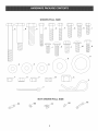
486.245042
SHOWN FULL SIZE
]
i
i
D
C
J
J
J
i
i
ii
ii
i
$
FI
O
__
U
V
_1 _
J
X
Z
Y
._JJ
NOT SHOWN FULL SIZE
AA
CC
6
[3{?
J
ATTENTmON!
Keep contents
of each hardware
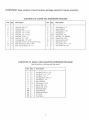
CONTENTS
Qty.
A
B
C
D
F
G
I
J
L
M
N
3
2
1
2
4
4
25
4
4
12
2
package
OF LARGE VAC HARDWARE
Description
Hex Bolt, 3/8" x 3"
Shoulder Bolt
Hex Bolt, 1/2" x 1ol/2"
Hex Bolt, 1/4" x 1o3/4"
Hex Bolt, 1/4" x 1ol/4"
Hex Bolt, 5/16" x 1"
Hex Bolt, 1/4" x 3/4"
Carriage Bolt, 1/4" x 3/4"
Hex Bolt, 5/16" x 3/4" Thread Forming
Bolt, Truss Head 5/16" x 3/4"
Bolt, Curved Head 1/4" x 1"
CONTENTS
separate
OF SMALL
Ref.
Qty.
O
P
R
S
T
U
V
W
X
Y
Z
2
4
1
4
35
2
16
5
1
2
1
DECK ADAPTER
Description
E
F
H
K
O
P
Q
T
V
AA
BB
CC
DD
EE
Hex Bolt, 5/16" x 1ol/4"
Hex Bolt, 1/4" x 1ol/4"
Hex Bolt, 1/4" x 1"
Carriage Bolt, 5/16" x 1"
Flat Washer, 1/4"
Nylon Washer
Fiat Washer, 5/16"
Nylock Nut, 1/4"
Nylock Nut, 5/16"
Mounting Strap
Angle Bracket
Mounting Bracket
"S" Hook
Tarp Strap
2
2
4
2
4
5
12
4
3
1
1
1
2
2
7
assembly°
PACKAGE
Description
Flat Washer, 1/4"
Nylon Washer
Flat Washer, 7/16"
Flat Washer, 1"
Nylock Nut, 1/4"
Hex Nut, 1/4" (SEMS)
Nylock Nut, 5/16"
Hex Lock Nut, 3/8"
Nylock Nut, 1/2"
Pin, Cotter 1/8" x 1ol/2"
Hair Cotter Pin, 1/8"
HARDWARE
Not a// parts in this bag wifl be used.
Refo i Qty,
for easier
PACKAGE
4
..... 3
18
19
20
j21
22
23
25
26
29
CARTON
Refo
1
2
3
4
5
6
7
8
9
10
11
12
13
14
15
16
Qty.
1
2
2
2
1
2
1
1
1
1
2
1
2
2
1
1
32
31
30
27
CONTENTS
Description
Cover
Top Connecting Tube
Support Tube, R,H,
Support Tube, LH,
Elbow (Discharge Chute)
Deck Adapter
Hose2
Hose Hanger Rod Assembly
Hose Adapter (Nozzle)
Engine
Hose Clamps
Tailgate
Cart Bodies
Wheels
Tailgate Reinforcement Bracket
Wheel Support
Ref.
Qty.
17
18
19
2O
21
22
23
24
25
26
27
28
29
3O
31
32
33
1
1
1
1
1
1
1
1
1
2
1
1
2
1
2
2
2
Description
Latch Stand Bracket
Front Panel
Axle
Front
Rear
Hose
Hitch
Hitch
Tongue
Tongue
Hanger Bracket
Plate
Pin
Rubber Strap
Tailgate Guide
Front Tube Support Bracket, R,H,
Front Tube Support Bracket, LH,
Rear Tube Support Bracket
Deck Adapter Bracket
Hub Caps
Wheel Spacers
Plastic Wheels
Thisunitis shippedWFHOUTGASOLINE
orOIL. After
assembly,
seeseparateenginemanualforproperfuel
andengineoil recommendations,
TOOLS REQUIRED FOR ASSEMBLY
(1) Screwdriver
(1) Pliers
(1) 3/8"Wrench
(2) 7/16"Wrenches
(2) 1/2"Wrenches
(2) 9/16"Wrenches
(1) 3/4"Wrench(2)if hitchplateinfig,21is used
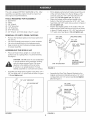
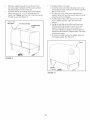
REMOVAL
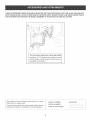
Fit the tailgate reinforcement bracket around the end
of the cart body, Fasten it to the top flanges of the
cart body using two 1/4" x 3/4" hex bolts and 1/4"
nylock nuts, Do not tighten yet. See figure 2,
Fasten the tailgate reinforcement bracket to the
bottom of the cart body using four 5/16" x 3/4" truss
head bolts and 5/16" nylock nuts as shown in figure 2,
Do not tighten yet.
Position the tailgate guides on the inside of the cart
bodies with the guide channels to the front as shown
in figure 2. Fasten using six 1/4" x 3/4" hex bolts and
1/4" nylock nuts. See figure 2. Do not tighten yet.
OF PARTS FROM CARTONS
1/4" x 3/4"
,
Remove the hardware packs and all loose
the cartons,
Lay out and identify parts shown in carton
Lay out and identify parts in the hardware
Keep contents of each hardware package
for easier assembly,
ASSEMBLING
parts from
contents,
packs,
separate
1/4"
NYLOCK
NUT
TAILGATE
HEX BOLT
//1/4"
._/REX
"®-
GUmBE
x 3/4"
BOLT
5/16" x 3/4" TRUSS
HEAD BOLT
/
THE MOW-N-VAC
Place cart body halves upright on a smooth level
surface such as a garage floor or a paved driveway,
See figure 1.
CAUTION: Do not leave the cart unattended
in upright position during assembly, A falling
cart can cause personal injury! Pay close
attention to the stability of the cart while
it remains in an upright position, For best
stability, assemble on a smooth level surface,
Assemble cart body halves together using three 1/4" x
3/4" hex bolts and 1/4" ny!ock nuts as shown in figure
1. Do not tighten yet,
1/4" x 3/4" HEX BOLT
TAILGATE
REINFORCEMENT
5/16" NYLOCK
NUT
BRACKET
FIGURE 2
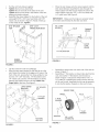
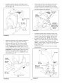
Assemble the Rear Tube Support Brackets to the
tailgate reinforcement bracket using four 1/4" x 3/4"
carriage bolts and 1/4" nylock nuts. Do not tighten
yet. See figure 3.
1/4" NYLOCK NUT
1/4" x 3/4"
CARRIAGE
©
1/4" NYLOCK
NUT
FIGURE 1
FIGURE 3
BOLT
/
.
.
.
Pul!thecartbodyhalvestogether.
Place the rear tongue onto the wheel support and the
latch stand bracket. Assemble the axle through the
wheel support and the tongue. Fasten the axle to the
wheel support using two 1/4" x 1o3/4" hex bolts and
1/4" nylock nuts. See Figure 6.
Tighten the four truss head bolts.
Tighten the six hex bolts in the sides of the cart.
Tighten the three hex bolts in the bottom of the cart,
keeping the bottom aligned.
Assemble the wheel support to the bottom of the cart
using eight 5/16" x 3/4" truss head bolts and 5/16"
ny!ock nuts as shown in figure 4. Heads of bolts go
on the inside of cart. Tighten.
5/16" NYLOCK
NUT
IMPORTANT:
Make sure the tongue is securely locked
to the latch stand bracket by the latch lock lever.
1/4" x I-3/4"'
HEX BOLT
5/16" × 3/4"
TRUSS HEAD BOLT
AXLE
/
TONGUE
FIGURE 6
FIGURE 4
Lay the cart down onto it's top flanges.
Align the latch stand bracket so that the tab is at the
rear. Fasten the bracket to the rear set of holes at the
front of the cart, leaving the front holes empty for now.
Use two 1/4" x 3/4" hex bolts, 1/4" flat washers and
1/4" nylock nuts. Use the 1/4" flat washers as shims
between the bracket and the cart bed. Make only
finger tight at this time. See figure 5.
LATCH STAND
BRACKET
Assemble a spacer tube onto each end of the axle as
shown in figure 7.
Assemble a 1" flat washer, a wheel (valve stem facing
out), and another 1" flat washer onto the axle as
shown in figure 7. Secure the wheel with a 1/8" x 1=
1/2" cotter pin, spreading the ends so that a hub cap
will fit over the pin. Assemble the hub cap by pressing
it onto the flat washer. Repeat on other end of axle.
1/4" NYLOCK
NUT
SPACER
rear)
/
@
TUBE
WHEEL
\
1/4" FLAT
1" FLAT
WASHER
\_'
1"FLAT
WASHER
\
HUB CAP
1/4" x 3/4"
HEX BOLT
FIGURE 7
FIGURE 5
10
1/8" × 1ol/2"
COTTER PIN
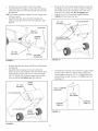
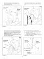
Flipthecartoversothatit restsonitswheels.
Assemble
thefronttongueontopofthereartongue
usingthree3/8"x 3"hexboltsand3/8"hexlocknuts.
Seefigure8.
HINT:Foreasierassembly,
supportthereartonguewith
a blockofwood.
Assemble
thehitchpintothehitchbracketand
tongue,securingitwiththe1/8"haircotterpin.See
figure8.
.
Place the R.H. Front Tube Support Bracket under the
top flanges of the cart, as shown in figure 10. Fasten
the bracket to the cart using three 1/4" x 3/4" hex
bolts and 1/4" nylock nuts. Do not tighten yet.
Repeat for the LH. Front Tube Support Bracket.
Tighten a!l loose bolts and nuts.
1/4" NYLOCK NUT
1t4" × 3/4"
\
HITCH
PmN
3/8" x3"'
HE× BOLT
TONGUE
(FRONT)
R.H. FRONT
SUPPORT
TUBE
/
\
\
\
\
\
\
\
/
BRACKET
1/8" HAiR
COTTER P{N
FIGURE 10
FIGURE 8
Release the latch lock lever and tilt the cart bed back.
See figure 9.
Assemble the front panel to the cart, sliding the
bottom lip of the panel between the cart and the latch
stand bracket. Secure with six 1/4" x 3/4" hex bolts
Assemble the reduced ends of the R=H=support tubes
into the ends of the LH= support tubes= Fasten the
tubes together using two 1/4" x 1" curved head bolts,
inserted from the top, and two 1/4" (SEMS) hex nuts=
See figure 11=
and 1/4" ny!ock nuts. Leave the upper holes on the
sides empty. Do not tighten yet. See figure g.
FRONT
1/4" x 3/4"
HEX BOLT
PANEL
114" × 1"' CURVED
HEAD BOLT
\
\
1/4" NYLOCK NUT
\
\
\
\
\
\
\
/
1t4" NYLOCK NUT
/
I
LATCH
STAND
BRACKET
FIGURE 11
FIGURE 9
11
To install the fabric cart cover:
Place the support tubes down into the front and
rear tube support brackets, with the tube's welded
brackets facing the center of the cart,
Assemble the top connecting tubes to the support
tubes using four 1/4" x 1ol/4" hex bolts and 1/4"
nylock nuts, Tighten unti! the end of the bolt extends
through the nut, See Figure 12,
114"× 1-1/4"
HEX BOLT
1, Unzip the cover's rear flap and place cover on top
of the support tubes, making sure that the zippered
flap is at rear of cart,
2, Pull the front of the cover down over the front
support tubes and hook the cover's plastic channel
under the cart's front flange,
3, Pul! the sides of the cover down and hook the
cover's plastic channel under the cart's side
flanges,
4, Swing the rear flap up onto the top of the cover,
Starting at the top, secure the cover to the rear
support tubes with the three vetcro straps on
each side, Tighten the straps so that the zipper is
pulled around behind the support tubes, The zipper
should close easily,
5, Unzip the rear flap to place the tailgate down into
the tailgate guides, See Figure 13,
1/4" NYLOCK NUT
/
TuBEOONNEOT'NG
Cover
FIGURE 12
FIGURE 13
12
Assemble a plastic wheel to each engine mount
bracket using a 3/8" shoulder bolt and 3/8" hex lock
nut. See Figure 14.
Remove the hex bolts, lock washers and hex lock
nuts from the two holes in the impeller housing
as shown in figure 16. Assemble the hose hanger
bracket to the two holes using the bolts, lock washers
and lock nuts which you removed.
USETHESE
HOLES
3/8"SHOULDER
3/8" HEX
LOCK NUT
USE PRE°
ASSEMBLED
BOLTS, LOCK
WASHERS AND
NYLOCK
NUTS
FIGURE 16
Assemble the elbow to the impeller housing using
four 5/16" x 3/4" thread forming bolts and four nylon
washers. Push while turning to help start the bolts
into the unthreaded holes. Tighten. See figure 17.
If the elbow does not align with the cover opening:
Step I Loosen the four bolts shown and adjust the
position of the engine base. Retighten the bolts.
Step 2 Loosen (about 1/4 turn) the four bolts shown.
Push against the elbow to center it in the opening.
Retighten the bolts.
Pull the boot onto the end of the elbow and tighten
the draw string.
FIGURE 14
Attach the vac tongue to your tractor's draw bar for
easier mounting of the engine base assembly.
Align the engine base with the tongue's welded
angles. Tilt the engine base back on it's wheels
so that the ends of the mount brackets rest on the
tongue, underneath the welded angles. Lift up on
the engine base and slide the engine mount brackets
underneath the welded angles. Fasten the mount
brackets to the welded angles using four 5/16" x 1"
hex bolts and 5/16" nylock nuts. Tighten the bolts
securely. See figure 15.
ELBOW
\
I/
\
\
NYLON
WASHER
5/18"
x 3/4"
HEX BOLT
(Thread
5/16" x 1"
HEX BOLT
_>_
5/16" NYLOCK
NUT
FIGURE 17
FIGURE 15
13
Forming)
Loop the 25" tarp strap under the hose. Fasten the
hooks to the hose hanger rod assembly. See figure
20.
Place the hose hanger rod assembly down into
the hose hanger bracket on the impeller housing
assembly. See figure 18.
HOSE HANGER
ASSEMBLY
'\
'/
BOSEHANGER
ASSEMB_
25" TARP
STRAP
FIGURE 20
FIGURE 18
,
,
Place a hose clamp onto the end of the hose. Push
the hose onto the hose adapter (nozzle). Tighten the
hose damp onto the hose and hose adapter. Do not
collapse the hose adapter when tightening the
clamp. See figure 19.
The remaining hose clamp will be used later to fasten
the hose to the deck adapter.
Assemble the hitch plate to the tractor hitch if:
a. Your tractor has a square (straight) hitch frame,
to help prevent binding.
b. Your tractor has a lightweight hitch frame that
needs reinforcement for towing.
Use a 1/2" x 1ol/2" hex bolt, a 7/16" flat washer and a
1/2" nylock nut. See figure 21
1/2" × 1ol/2"
HEX BOLT
HOSE ADAPTER
TRACTOR
(NOZZLE}
(SQUARE)
HUTCH FRAME
!
CLAMP
HOSE
7/16" FLAT WASHEBj_
1/2" NYLOCK
FIGURE 21
FIGURE 19
14
NUT
ATTACH
MOW°N°VAC
HERE
ASSEMBLING
THE #62468
TO THE MOWER DECK
DECK
ADAPTER
Position the adapter over the deck opening, and
check for fit of cutout as shown in figure 23. Trim
cutout, if necessary, to allow tilting of adapter,
keeping the fit as close as possible for best vacuum
suction.
NOTE: Not al! of the parts in the deck adapter hardware
package will be used for any one particular fit up.
.
Remove the mower discharge deflector from your
mower deck. Save the deflector and hardware for
remounting deflector.
NOTE:
Make sure sdspter
wheels
co mower
cmesrs gauge
deck
DECK ADAPTER
CAUTION: Mower deflector must be
replaced when Vac System deck adapter
is removed. Do Not operate mower
unless adapter or deflector is in place and
properly mounted.
MOWER DECK
FITTING TO SEARS TRACTORS
The yellow fold out sheet contains the templates for
Sears tractors only. (The white fold out sheets include all
templates, including other tractor brands.)
ff you have a Murray brand tractor with a 38", 40" or 46"
deck, go directly to the instructions on pages 16 and 17.
FIGURE
identify and cut out the template for your brand and
size mower deck. If there is no template included for
your deck size, you can make your own template by
marking around a piece of cardboard held against the
edge of the deck's discharge opening.
Curl on
sdspter
deck may
or inside
opening
design
be 1costed
depending
outside
of
or_ deck
23
Holding the adapter bracket and the deck adapter
together, position the deck adapter on the mower
deck. Keeping the edge of deck adapter as close as
possible to the offset in the adapter bracket, see if the
slot in the adapter bracket can be aligned with one
or two of the deflector holes in your mower deck's
discharge opening. If the bracket can not be located
correctly using existing holes, it will be necessary to
drill one or two 5/16" diameter holes in the deck. See
FOLLOW THE INSTRUCTIONS PRINTED ON THE
TEMPLATE. If there are no instructions, use the
following instructions as a general guide.
Tape the template to the face of the adapter, about
1/2" from front and 1/4" down from top for deeper
decks. For shallow decks, position template low
enough that adapter will not extend below bottom
of deck. Mark outline of template on face of adapter
using white crayon, nail or scriber. Drill a starting
hole inside the outline, then use a saber saw or key
hole saw to cut out the opening. See figure 22.
figure 24.
Use e×ieting holes or drill 5/16"
diameter hole or holes.
1/4" DOWN
\
_\\\\\\\\\\
/
DECK
ADAPTER
/
MOWER
/
Keep edge of adapter as close
as possible to offset in bracket
1/2" FROM FRONT
FIGURE
FIGURE 24
22
15
DECK
Assemble
theadapterbrackettothedeckusingtwo
5/16"x 1-1/4"hexbolts,5/16"flatwashersand5/16"
nylocknuts.Seefigure25.
FOR 1990 AND NEWER MURRAY
WITH A 38" OR 40" DECK
NOTE:It maybenecessary
to useextra5/16"flat
washerstoshimunderthebracketnexttothedeck
surface.Tenextrawashershavebeenfurnishedas
shims.Seefigure25.
TRACTORS
Cut out two templates and place on deck adapter
as shown in figure 33. Tape smaller one on top and
larger one on the side and bottom= After they are in
place, carefully mark around the templates, then cut
out adapter to obtain correct opening.
(2) 5/16" NYLOCK
Bolt end of mounting strap to the 5/16" bolt on the
mower deck=The other end of the strap will bolt to
a hole in the deck adapter, which must be drilled.
Position the adapter on the deck, then drill a 5/16"
hole in the bottom of the adapter that will align with
the hole in the strap= Fasten the adapter to the strap
using one 1/4" x 1" hex bolt, 1/4" flat washer, nylon
washer and 1/4" nylock nut. See figure 27.
5/16" FLAT
WASHERS
38"/40" TEMPLATE
TEMPLATE
TO CUT OUT SLOT
CUT OUT SLOT IN TOP
OF DECK ADAPTER
FIGURE 25
1t4" × 1" HEX BOLT
1/4" FLAT WASHER
With deck adapter positioned correctly over the
discharge opening, use the adapter bracket as a
template and drill three 9/32" diameter holes in the
top of the deck adapter. See figure 26.
I
Bolt deck adapter to bracket using three 1/4" x 1"
bolts, nylon washers, 1/4" fiat washers and 1/4"
nylock nuts. Ny!on washers should be against the
inside of the deck adapter. See figure 26.
DECK
NYLON WASHER
MOUNTmNG
BOLT THBS END OF
STRAP TO 5/16" BOLT
ON MOWER DECK
NUT
ADAPTER
(3) 1/4" NYLOCK
NUTS
J
(3) NYLON
WASHERS
_
-
FIGURE 27
ADAPTER
BRACKET
MOWER DECK
(3) 1/4" STEEL WASHERS
(3) 1/4" x 1" HEX BOLTS
FIGURE 26
,
1/4" NYLOCK
STRAP
Assemble end of hose and a hose clamp over the
round opening of deck adapter and tighten clamp.
GO DJRECTLYTOTNE OPERATION INSTRUCTIONS
ON PAGE 18.
16
Assemble end of hose and hose clamp over the
round opening of deck adapter and tighten clamp.
GO DIRECTLYTOTNE OPERATION INSTRUCTIONS
WHICH ARE LOCATED ON PAGE 18.
FOR 1990 AND NEWER
WITH A 46" DECK
MURRAY
TRACTORS
Tape 46" template onto deck adapter, Mark and then
cut out adapter,
Fasten the angle bracket and the mounting bracket
to the mower deck as shown in figure 34, Use two
5/16" x 1" carriage bolts, 5/16" flat washers and 5/16"
nylock nuts, The bolt heads go on inside of mower
deck,
Drill two 5/16" diameter holes in the deck adapter
that will align with the holes in the angle bracket and
the mounting bracket, Assemble the deck adapter to
both brackets using two 1/4" x 1" hex bolts, 1/4" flat
washers, nylon washers and 1/4" nylock nuts, See
figure 28,
I
ANGLE
NYLON
BRACKET
1
"' NYLOCK
WASHER
\
NUT
x MOUNTING
1/4" FLAT
,\
114"x 1
LOCATE
AND
DRILL ROLES
\
NYLON
WASHER
-._
114" FLAT WASHER _,
114"
x1"NEX
BOLT
FIGURE 28
Assemble end of hose and hose clamp over the
round opening of deck adapter and tighten clamp,
GO DIREOTLYTOTHE OPERATION iNSTRUCTIONS
WHICH ARE LOCATED ON PAGE 18.
17
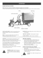
KNOW YOUR VAC SYSTEM
Read this owner's manual and safety rules before operating your Vac System.
Compare the illustration below with your Vac System to familiarize yourself with the various controls and their locations,
BOOT
LATCH
LOCK
REAR FLAP
LEVER
\
CHOKE CONTROL
THROTTLE
LATCH LOCK LEVER Locks the cart bed down to the
tongue, Releases to allow cart to be tipped back for
dumping=
CONTROL
REAR FLAP Zippered flap opens to allow contents of cart
to be emptied,
THROTTLE CONTROL
BOOT Connects the plastic elbow to the fabric top,
directing discharged material into the cart,
CHOKE CONTROL
BEFORE
CAUTION:
Alcohol blended fuels (called gasohot or using
ethanol or methanol) can attract moisture which leads to
separation and formation of acids during storage. Acidic gas can
damage the fuel system of an engine while in storage.
Controls speed of engine,
Adjust to allow cold starting,
STARTING
Your Vac System engine is shipped without oil or
gasoline, Service the engine with oil and gas as
instructed in the separate engine manual,
Inspect the Vac System to make sure all covers (rear
door, vinyl boot, elbow, hose adapter, hose and deck
adapter are properly attached,
Check tires for proper inflation (12 - 14 Ibs),
To avoid engine problems, the fuel system should be emptied
before storage for 30 days or longer. Drain the gas tank, start
the engine and let it run until the fue! lines and carburetor are
empty. Use fresh fuel next season. See
STORAGE Instructions for additional information.
Never use engine or carburetor cleaner products in the fuel tank
or permanent damage may occur.
HOW TO STOP YOUR VAC SYSTEM
To stop engine, move the throttle contro! lever to the
OFF position,
Disconnect spark plug wire from plug to prevent
accidental starting while equipment is unattended or
is being worked on,
WARNING: Never fill fuel tank indoors,
or with the engine running, or while the
engine is hot, Do not smoke while filling
tank,
CAUTION:
are hot!
18
The muffler and adjacent areas
HOWTO START YOUR VAC SYSTEM
CAUTION: To avoid possible injury, be
sure that no one is near the cart before
releasing the latch lock lever,
WARNING: Never start or run the engine
without al! covers being properly attached to
the blower housing and cart,
,
,
,
,
,
,
,
Check oil and gas in Vac engine,
Attach spark plug wire to spark plug,
Move choke lever on engine to CHOKE position,
(A warm engine may not require choking,)
Move throttle control lever on engine to FAST
position=
Grasp starter handle and pull rope out slowly until
engine reaches start of compression cycle (rope will
pull slightly harder at this point), Let the rope rewind
slowly,
Putl rope with a rapid, continuous, full arm stroke,
Keep a firm grip on starter handle, Let rope rewind
slowly, Do not let starter handle snap back against
starter,
Repeat instructions in two preceding paragraphs until
engine fires, When engine starts, move choke control
gradually to RUN position,
,
TO USE THE CART WITHOUT THE VAC SYSTEM
Unzip the rear flap and unfasten the velcro fasteners,
Remove and store the soft top cover,
,
Remove the tube frame in one piece and store,
are
hot!
CAUTION:
inspect the Vac to make sure the cover, rear door,
boot, elbow, hose adapter (nozzle), hose and deck
adapter are properly attached,
Check tires for proper inflation (12 - 14 Ibs),
Check for oil and gas in Vac engine,
Begin operation at low speed, adjusting forward
speed to match grass height and/or moisture
condition to prevent clogging,
Do not attempt to vacuum up any material other
than vegetation found in a normal yard, such as light
branches, leaves, twigs, etc,
WARNING: Should your Vac System
become clogged, shut off tractor and Vac
engines, Before attempting to unclog,
remove wire from spark plug to prevent
accidental starting,
TO EMPTY THE CART
,
The muffler and adjacent areas
Remove and store the four bolts and nuts which
fasten the engine base to the tongue,
Slide the engine off the tongue and roll to a safe
storage area,
CAUTION:
Vehicle braking and stability
may be affected with the addition of an
accessory or an attachment, Be aware of
changing conditions on slopes,
,
Using a rake or suitable too!, pull grass clippings and/
or leaves out of the cart,
After the cart is emptied, tip it forward and secure it to
the tongue with the latch tock lever, Install the tailgate,
place the bottom of the rear flap inside the tailgate
and zip the rear flap shut,
HOW TO USE YOUR VAC SYSTEM
,
Remove the tailgate,
Release the latch lock lever on the tongue and tip the
cart back,
Shut off the tractor engine and set the brake,
Shut off the Vac engine,
Loosen the draw string and pul! the boot back from
the elbow,
Unzip the rear flap, flip it up and secure it with the
velcro strips on top of the cover,
19
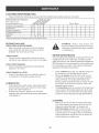
CUSTOMER RESPONSIBILmES
,
Read and follow the maintenance schedule and the maintenance
MAINTENANCE SCHEDULE
Fil! in dates as you
complete regular service.
Check
for loose
procedures listed in this section.
_..J
_
,o_
fasteners
Service Dates
X
Check cover
Check tire pressure
X
X
Che_keng!ne_!!!eve!
X
Lubricate
X
Clean
!
lxl
IX
Maintain engine per instructions below and in engine manual
BEFORE
EACH USE
WARNING:
Always stop engine and
disconnect spark plug wire before cleaning,
lubricating or before performing any repairs
or maintenance.
CHECK FOR LOOSE FASTENERS
,
Make a thorough visual check of the Vac System
for any bolts and nuts which may have loosened.
Retighten any loose bolts and nuts.
ENGINE
CHECK COVER
Check the cover, especially the front boot and the
rear flap for wear. Replace cover if worn or damaged.
CHECK TIRE PRESSURE
Check tire pressure regularly. Recommended tire
pressure is 12-14 Lbs.
.
CHECK ENGINE OIL LEVEL
Check oil level before each use. Maintain engine oil
as instructed in the separate engine manual.
.
.
MAINTENANCE
Only use high quality detergent oi! rated with API service
classification SF or SG. Select the oil's SAE viscosity
grade according to your expected operating temperature.
SAE 30 grade oi! is recommended for warm weather use.
For cold weather use refer to the engine manufacturer's
Operating and Maintenance Manual.
At the beginning of each season, lubricate the latch,
latch pivot bolt, and the axle where the hitch tongue
pivots, with a light machine oil.
At least once a season, grease or oil the wheel
bearings. Use automotive wheel bearing type grease
or 20 weight oil.
Check oH level before each use. Maintain engine oil
as instructed in the separate engine manual.
Service air cleaner every 25 hours under normal
conditions. Clean every few hours under extremely
dusty conditions. Poor engine performance and
flooding usually indicates that the air cleaner should
be serviced. To service the air cleaner, refer to the
separate engine manual.
The spark plug should be cleaned and the gap reset
once a season. Spark plug replacement at the start
of each season is recommended. Check the engine
manual for correct plug type and gap specifications.
CLEANING
Make sure the cart and top are cleaned after each
use. Grass clippings and leaves left in the cart will
mildew and cause damage if not cleaned out.
Clean the engine regularly with a cloth or brush.
Keep the cooling fins on the engine housing clean
to permit proper air circulation which is essential to
engine performance and life. Be sure to remove all
dirt and debris from muffler area.
20
Clean the engine and the entire unit thoroughly.
Refer to engine manual for correct engine storage
instructions.
it is important to prevent gum deposits from forming in
essential fuel system parts such as the carburetor, fuel
filter, fuel hose or tank during storage. Also, alcohol
blended fuels (called gasohol or using ethanol or
methanol) can attract moisture which leads to separation
and formation of acids during storage. Acidic gas can
damage the fue! system of an engine while in storage.
if storing in an unventilated or metal storage shed,
coat metal parts with light oil or silicone to prevent
rust.
Store unit in a clean, dry area.
To avoid engine problems, the fuel system should be
emptied before storage of 30 days or longer. Follow the
instructions in the engine's Operating &
Maintenance Manual.
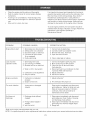
PROBLEM
POSSIBLE CAUSE(S)
CORRECTIVE ACTION
Engine fails to start
1.
2.
3.
4.
Spark plug wire disconnected.
Safety switch not contacted.
Fuel tank empty, or stale fuel.
Fuel shut-off valve closed
(if so equipped).
5. Faulty spark plug.
1.
2.
3.
4.
1. Spark plug wire loose
2. Unit running on CHOKE.
3. Blocked fuel line or stale fuel.
1. Connect and tighten spark plug wire.
2. Move choke lever to OFF position.
3. Clean rue! line; fill tank with clean
fresh gasoline.
4. Disconnect fuel line at carburetor to drain
fuel tank. Refill with fresh fuel.
5. Adjust carburetor.*
6. Service air cleaner.*
Loss of power;
operation erratic.
5. Clean, adjust gap or replace.
4. Water or dirt in fuel system.
Carburetor out of adjustment.
6. Dirty air cleaner.
5.
Engine overheats
2.
Too much vibration
Unit does not
discharge
Connect wire to spark plug.
Correctly install hose adapter nozzle.
Fil! tank with clean, fresh fuel.
Open fuel shut-off valve.
Carburetor not adjusted
properly.
Engine oil level low.
1. Adjust carburetor.*
2. Fill crankcase with proper oil.
Loose parts or damaged
impeller.
Stop engine immediately and disconnect
spark plug wire. Tighten al! bolts and nuts.
Make all necessary repairs. If vibration
continues, have unit serviced by an
authorized service dealen
1. Discharge chute (elbow)
dogged.
1. Stop engine immediately and disconnect
spark plug wire. Clean inside of housing
and discharge chute (elbow).
2. Stop engine immediately and disconnect
spark plug wire. Remove lodged object.
3. Empty cart.
2. Foreign object lodged in
impeller.
3. Vac Cart is full.
*Refer to the engine manual packed with your unit.
NOTE: For repairs beyond the minor adjustments listed above, please contact your nearest authorized service dealer.
21
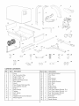
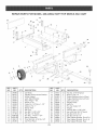
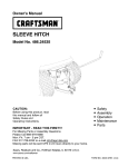
REPAIR PARTS FOR MODEL 486.245042
11
26
SOFT TOP MOW-N-VAC
CART
22
\
\
32
/
11
12
31
12
17
12
23
20
lO
\
\
13
j
28
14
19
27
RER
NO.
PART
NO.
QTY.
1
2
3
4
5
6
7
8
9
10
11
12
13
14
15
16
24096
62457
23487
24497
24984
43594
43093
43601
48637
43014
43012
47189
1509-69
HA20186
43814
23490
2
1
1
1
1
2
2
4
2
2
25
31
2
1
12
1
DESCRIPTION
REFo
NO.
Cart Body
Tailgate Reinforcement Bracket
Wheel Support
Latch Stand Bracket
Axle, Wheel 1" Di&
Wheel w/Tire
Cotter Pin, 1/8" Dia, x 1ol/2"
Washer, Flat 1"
Spacer Tube
Hub Cap
Hex Bolt, 1/4-20 x 3/4"
Hex Nut, 1/4" Ny!ock
Hex Bolt, 1/4-20 x 1o3/4"
Spring, Extension
Truss Hd. Bolt, 5/16-18 x 3/4"
Cart Front Panel
17
18
19
20
21
22
23
24
25
26
27
28
29
30
31
32
23
PART
NO.
47810
43088
64551
64531
25010
23548
43884
43343
23504
44950
43082
47407
43574
24960
24959
25539
QTY.
13
2
1
1
1
2
1
1
1
4
3
1
3
1
1
2
DESCRIPTION
Hex Nut, 5/16-18 Nylock
Washer, Fiat 1/4"
Tongue Weldment Ass'y, (Rear)
Tongue Weldment Ass'y, (Front)
Latch Lock Lever
Tailgate Guide
Hitch Pin
Pin, Hair Cotter 1/8"
Tailgate
Carriage Bolt, 1/4-20 x 3/4"
Hex Lock Nut, 3/8-16 Thread
Hex Bolt, 5/16-18 x 4"
Hex Bolt, 3/8-16 x 3"
Tube Support Bracket, Front R,H,
Tube Support Bracket, Front LH,
Tube Support Bracket, Rear
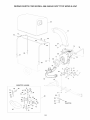
REPAIR PARTS FOR MODEL 486.245042
f.f
SOFT TOP MOW-N-VAC
1"
23
J
t
I
\
\
\
27
37
14
I
38
4
18
/
;
19
,
2
i
I
I
....
: ; ! _i
i
I
4O
/
/
TRACTOR
12
32
_ 13
24
REPAIR PARTS FOR MODEL 486.245042
iRER
i NO.
!
1
i 2
3
4
i 5
i 6
7
i 8
9
12
13
14
15
16
17
18
19
20
21
22
23
24
25
26
27
28
29
3O
31
32
PART
NO.
QTY.
734-0973
24957
24956
43182
43840
43085
738=0373
47810
43791
43661
47189
!21312_@E1
222261
63227
46420
43792
43793
48634
64647
64648
48640
43790
43088
23540
1543-69
43020
712=3083
43352
43081
43830
2
2
1
4
2
4
2
17
1
4
7
1
1
1
1
1
2
2
2
2
1
1
4
1
9
1
1
1
12
1
DESCRIPTION
SOFTTOP
RER
NO.
PART
NO.
QTY.
33
34
35
36
37
38
39
23560
44326
23825
23826
47630
'12-0421
1
2
1
1
4
3
1
4O
62468
1
41
42
44
45
46
47
48
49
23827
1509-90
43063
43978
46978
43082
44849
44850
49939
1
6
4
2
2
2
2
2
1
Engine Wheel
Engine Mount Bracket
Engine Base
Bolt, Hex 5/16=18 x 3/4"
Bolt, Hex 5/16=18 x 1=1/4"
Bolt, Hex 5/16=18 x 1=1/2"
Shoulder Bolt
Nut, Hex 5/16=18 Nylock
Hose Adapter
Bolt, Hex 1/4=20 x 1"
Nut, Hex 1/4=20 Nylock
Engine, B & S 6.5 HP
Deflector, Muffler
Hose Hanger Rod Ass'y.
Elbow
Hose (6" x 84")
Hose Clamp 6"
Top Connecting Tube
Support Tube, LH.
Support Tube, R.H.
Cart Cover
Strap, Tarp 25"
Washer, 1/4" STD
Hitch Plate
Washer, Ny!on 21/64"
Bolt, Hex 1/2-13 x 1-1/2"
Nut, Hex 1/2-13 Nylock
Washer, Flat 7/16"
Washer, 5/16" STD
Adapter, Deck
25
MOW-N-VAC
DESCRIPTION
Bracket, Deck Adapter
Bolt, Carr. 5/16" x 1"
Mounting Strap
Angle Bracket
Screw, Self Tap 5/16"-18 x 3/4"
Knob (See also Item #8, Page 22)
Impeller Housing Assembly
(See Page 22)
Deck Adapter Kit (Includes parts
in box shown on page 20)
Mounting Bracket
Bolt 1/4o20 x 1-1/4"
Bolt, Hex 5/16-18 x 1"
Bolt, Curved Hd. 1/4-20 x 1"
Nut, Hex 1/4=20 SEMS
Nut, Hex Lock 3/8-16
"S" Hook
Tarp Strap
Owner's Manual
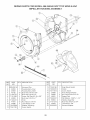
REPAIR PARTS FOR MODEL 488.245042 SOFTTOP
mMPELLER HOUSING ASSEMBLY
RER
NO.
PART
NO.
1 629-0241A
2
3
4
5
24634
24633
43182
710-0772
6 710-1268
43063
7
8
712-0421
47810
9
43086
10
11
719-0330A
12 725-1700
RER
NO.
QTY. DESCRIPTION
1
1
1
10
3
2
3
3
12
3
1
1
13
14
15
16
17
18
19
2O
21
22
23
Harness, Wire
Housing Ass'y. Inner
Housing Ass'y. Outer
Bolt, Hex 5/16-18 x 3/4"
Bolt, Hex 5/16-24 x 2"
Screw, Self Tap #10-16 x 3/8"
Bolt, Hex 5/16-18 x 1"
Knob
Nut, Nylock 5/16-18
Lock Washer, 5/16"
Adapter, Mounting
Cover, Switch
26
PART
NO.
725-3166
726-0272
731-1613
24958
48848
48591
736-0247
63924
710-1273
43003
629-0923
MOW-N-VAC
QTY. DESCRIPTION
1
1
1
1
3
2
1
1
1
1
1
Snap Mount Switch
Clamp
Cover, Switch
Hose Hanger Bracket
Nut, Nylock Jam 5/16-18
Spacer Rod
Flat Washer, 13/32" x 1-1/4"
Impetler Assembly
Bolt, Hex 3/8-24 x 2-3/4"
Lockwasher, 3/8"
Harness Adapter
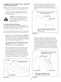
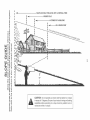
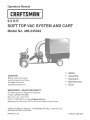
SIGHT AND HOLD THIS LEVEL WITH A VERTICAL TREE
@
A POWER POLE
03
O
A CORNEFI OF A BUILDING
_
.....
OR A FENCE POST
O
O
@ o
I
E
_fl
_o _o
b,('4
o
W_"-
@
OO. "
"J_o £. I
>,
0
i
ii
v@
o
@
4_
@
4_
_b
J_
@
I
CAUTION:
Do not operate your tractor and Vac System on a slope
in excess of 10 degrees. Be sure of your tractor's towing and braking
capabilities before operating on a slope. Avoid any sudden turns or
maneuvers while on a slope.
Your Home
For repair-in
your home-of all major brand appliances,
lawn and garden equipment, or heating and cooling systems,
no matterwho
made it, no matterwho
sold it!
Forthe replacement parts, accessories and
owner's manuals that you need to do-it-yourself.
For Sears professional installation of home appliances
and items like garage dooropeners
and water heaters.
1-800-4-MY-HOME
Call anytime,
®
(1-800-469-4663)
day or night (U.S.A. and Canada)
www.sears.com
www.sears.ca
Our Home
For repair of carry-in items like vacuums,
and electronics,
lawn equipment,
call or go on-line for the location of your nearest
Sears Parts & Repair Center.
1-800-488-1222
Call anytime,
dayornight
(U.S.A. only)
www.sears.com
To purchase a protection
or maintenance
agreement (Canada) on a product serviced by Sears:
1-800-827-6655
Para pedir servicio
a domicilio,
agreement (U.S.A.)
(U.S.A.)
1-800-361-6665
de reparaci6n
y para ordenar
1-888-SU-HOGAR
(Canada)
Au Canada pour service en fran(_ais:
1-800-LE-FOYER Mc
(1-800-533-6937)
piezas:
®
(1-888-784-6427)
® Registered
® Mama
MC
Marque
Trademark
Registrada
/
de commerce
TM
/
TM
Marea
/
MD
Trademark
de F_brica
Marque
/ SMService
/ SM Marea
d6pos6e
Mark of Sears
de Servicio
de Sears
Brands,
Brands,
de Sears
LLC
LLC
Brands,
LLC
© Sears Brands, LLC