1
I PROFESSIO
NAL
I
RECiPROCATiNG
Variable
SAW
Angme
Doubme lnsumated
ModeJ No.
353°28640
CAUTION: Read the Safety
GuideHines and AH instructions
Carefully Before Operating this tool
Sears,
A03284-
o
Safety
Guidelines
o
o
Maintenance
o
Service
o
Repair
Parts
Roebuck
and Co., Hoffman
Estates, mL(}0179 U.S.A.
Visit our Craftsman website: <www.sears.com!craftsman>
08-16-04
Espahol, p. 21
WARRANTY ................................................
SPECiFiCATiON
CHART .....................................
SAFETY GUiDELiNES
......................................
FUNCTIONAL DESCRiPTiON
.................................
BLADE iNSTALLATiON .....................................
2
2
3-7
7
7-9
ADJUSTMENTS
..........................................
OPERATION
...........................................
MAINTENANCE
............................................
ACCESSORIES
............................................
9-11
t 1-15
t6
16
SERVICE .................................................
TROUBLESHOOTING
......................................
REPLACEMENT
PARTS ..................................
NOTES
..................................................
ESPA_IOL ..............................................
17
17
t 8-19
20
21-35
HOW TO ORDER REPAIR PARTS ......................
ONE YEAR FULL WARRANTY
ON CRAFTSMAN
back cover
PROFESSIONAL
TOOL
this Craftsman Professional tool fails to give complete satisfaction
within one year from date of purchase, RETURN IT TO THE NEAREST SEARS
STORE OR SEARS PARTS & REPAIR CENTER IN THE UNITED STATES, and
Sears will repair it, free of charge=
This warranty gives you specific legal rights, and you may also have other
rights which vary from state to state.
Scars, Roebuck
and Co., Dept. 817WA, Noffman
Estates,
IL 60179
Model Number ..................................................................
353°28640
Voltage supply ..............................................................................
120V
Power consumption ..................................................................
1200W
Power output ..............................................................................
670W
Frequency .....................................................................................
60Hz
Strokes per minute ..........................................................
0-2900 SPM
Working ranges (max.)
Wood ..................................................................................
30.5 cm
Metal ....................................................................................
19 mm
A-weighted levels:
sound pressure level .............................................................
88 dB
sound power level ...............................................................
101 dB
Typical Mean effective Acceleration ......................................... 20 m/s _
6) Sears, Roebuck and Co.
A03284
2- ENG
Thismanual
contains
information
thatis important
foryoutoknowandunderstand.Thisinformation
relates
toprotecting
YOUR
SAFETY
andPREVENTING
EQUIPMENT
PROBLEMS.
Tohelpyourecognize
thisinformation,
weusethe
symbols
below.Please
readthemanual
andpayattention
tothesesections.
indicates
animminently
hazardous
situation
which,ifnot
avoided,
will
resultindeath
orserious
injury.
indicates
apotentially
hazardous
situation
which,ifnot
avoided,
could
resultindeath
orserious
injury.
indicates
apotentially
hazardous
situation
which,ifnot
avoided,may
resultinminor
ormoderate
injury.
usedwithout
thesafetyalertsymbol
indicates
potentially
hazardous
situation
which,if notavoided,
mayresultin
property
damage.
Some
dust
reated
bypower
sanding,
sawing,
grinding,
drilling,
andother
cconstruction
activities
contains
chemicals
known
(to
theStateofCalifornia)
tocause
cancer,
birthdefects
orotherreproductive
harm.
Some
examples
ofthesechemicals
are:
leadfromIead-based
paints
crystalline
silicafrombricksandcement
andothermasonry
products
® arsenic
andchromium
fromchemically-treated
lumber
Yourriskfromtheseexposures
varies,
depending
onhowoftenyoudothis
typeofwork.Toreduce
yourexposure
tothesechemicals:
workina wetI
ventilated
area,andworkwithapproved
safetyequipment,
always
wear
MSHA/NIOSH
approved,
properly
fittingfacemaskorrespirator
whenusing
suchtools.
Readandunderstand
aHinstructions,
Failure
to
allinstructions
listedbelow,mayresultinelectric
shock,fire
and/orserious
personal
injury.
SAVE
THESE
INSTRUCTIONS,
WORK
1o
AREA
Keep your work area clean and well mit.Cluttered benches and dark
areas invite accidents.
2,
Do not operate power tooms in expmosive atmospheres,
such as in
the presence of flammable liquids, gases, or dust, Power tools
create sparks which may ignite the dust or fumes.
3,
Keep bystanders, children, and visitors away while operating a
power tool Distractions can cause you to lose control.
ELECTRICAL
SAFETY
1,
2,
Double insulated tooms are equipped with a polarized pBug (one
bmade is wider than the other}, This plug will fit in a polarized outmet
only one way, If the plug does not fit fully in the outlet, reverse the
pmug, If it still does not fit, contact a qualified emectrician to install a
poBarized outBet, Do not change the plug in any way, Double
Insulation []
eliminates the need for the three wire grounded power
cord and grounded power supply system.
Avoid body contact with grounded surfaces such as pipes,
radiators, ranges and refrigerators,
There is an increased risk of
electric shock if your body is grounded.
3- ENG
A03284
3,
Don't expose power tooms to rain or wet conditions, Water entering
a power tool will increase the risk of electric shock.
4,
Do not abuse the cord, Never use the cord to carry the rooms or pull the
plug from an outmet, Keep cord away from heat, oil, sharp edges or
moving parts, Replace damaged cords immediately,. Damaged cords
increase the risk of electric shock.
5, When operating a power too_ outside, use an outdoor extension cord
marked "W-A" or "W", These cords are rated for outdoor use and reduce
the risk of electric shock.
PERSONAL
SAFETY
1, Stay alert, watch what you are doing, and use common sense when
operating a power tool, Do not use tool while tired or under the
influence of drugs, alcohom, or medication, A moment of inattention while
operating power tools may result in serious personal injury.
2,
Dress proper{y. Do not wear loose c_otHng or jewemry. Contain mong
hair. Keep your hair, cmothing, and gloves away from moving parts,
Loose clothes, ]eweIry, or long hair can be caught in moving parts.
3, Avoid accidental starting, Be sure switch is OFF before pgugging in,
Carrying tools with your finger on the switch or plugging in tools that have
the switch ON invites accidents.
4,
Remove adjusting keys or wrenches before turning the tool on, A
wrench or a key that is left attached to a rotating part of the tool may result
in personal injury:
5,
Do not overreach, Keep proper footing and balance at aH times, Proper
footing and batance enables better control of the tool in unexpected
situations.
6,
Use safety equipment. ABways wear eye protection, Dust mask, nonskid safety shoes, hard hat, or hearing protection must be used for
appropriate conditions.
7. Use certified safety equipment, Eye protection equipment shouid comply
with ANSI Z87.1 standards, hearing equipment should comply with ANSI
$3.19 standards, and dust mask protection should comply with
MSHA/NIOSH certified respirator standards.
8, Never touch blade immediatemy after use, Contact with a hot blade will
increase the risk of a bum.
TOOL USE AND CARE
1, Use cmamps or other practicaB way to secure and support the
workpiece to a stable platform, Holding the work by hand or against your
body is unstable and may lead to Ioss of control
2,
Do net force tool, Use the correct toom for your appBication, The correct
tool will do the job better and safer at the rate for which it is designed.
3,
Do not use toot if switch does not turn it on or off, Any toot that cannot
be controlled with the switch is dangerous and must be repaired.
4,
Disconnect the plug from the power source before making any
adjustments,
changing accessories, or storing the tool, Such preventive
safety measures reduce the risk of starting the toot accidentally.
5, Store idBe too{s out of reach of children and other untrained persons,
Tools are dangerous in the hands of untrained users.
6,
Maintain tooms with care, Keep cutting tooms sharp and cmean, Properly
maintained tools with sharp cutting edge are less likely to bind and are
easier to control
7, Check for misamignment or binding of moving parts, breakage of parts,
and any other condition that may affect the tool's operation, If
damaged, have the toom serviced before using, Many accidents are
caused by poorly maintained tools.
A03284
4- ENG
8,
Use only accessories that are recommended
by the manufacturer
for
your model Accessories that may be suitable for one tool may become
hazardous when used on another tool.
9, Use only accessories recommended
for this toom that are sold by Sears
or a Craftsman outlet, Use of any accessories purchased elsewhere may
be hazardous.
SERVICE
1, Tool service must be performed only by qualified repair personnel
Service or maintenance performed by unqualified personnel could result
in a risk of injury.
2, When servicing a tool, use onmyidenticam replacement parts, Folmow
instructions
in the Maintenance Section of this manual Use of
unauthorized parts or failure to follow Maintenance Instructions may
create a risk of shock or injury.
1,
2,
3,
4,
5.
Hold toom by insulated gripping surfaces when performing an
operation where the cutting tooB may contact hidden wiring or its
own cord, Contact with a "live" wire will make exposed metal parts of
the tool "live" and shock the operator.
Keep blades sharp, Sharp blades will do the iob better and safer.
Keep hands away from cutting area. When sawing never reach
underneath or behind the material being cut for any reason.
When you have finished a cut be careful not to come into contact
with the Made, Turn off the motor immediately.
Never homdwork in your hand, lap, or against other parts of your
body when sawing, The saw may slip and the blade could contact the
body, causing injury.
Exercise extreme caution when bBind cutting, Blade
contact with foreign objects such as electrical wire, conduit,
ptumbing pipes, etc., could result in a risk of shock or serious
injury.
Some wood contains preservatives which can be toxic,
Take extra care to prevent inhamation and skin contact when
working with these materiaBs, Dust or fumes from this
operation could cause breathing problems, skin irritation or
other injuries.
This tool was designed for certain applications
mikethose
described in this manual Incorrect use of this tool
could result in death or serious injury. DO NOT modify or use
this tool for any application for which it was NOT designed.
5-ENG
A03284
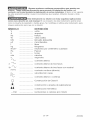
SYMBOL
V
A
Hz
W
kW
_F
........................
........................
........................
........................
........................
........................
........................
DEFINITION
volts
amperes
hertz
watts
kilowatts
microfarads
liters
kg
N/cm 2
Pa
h
min
........................
........................
........................
........................
........................
kilograms
newtons per square centimeter
pascals
hours
minutes
s
........................
seconds
........................
alternating current
3F'_
........................
three-phase alternating current
3N f-'LJ
........................
three-phase alternating current with neutral
........................
direct current
........................
no load speed
........................
alternating or direct current
........................
Class li Construction
........................
splash-proof
_
........................
watertight construction
._/min
........................
revolutions or reciprocation
n o
construction
per minute
MOTOR
Some tools will operate on either
D.C. or single phase 25 to 60 cycle
A.C. current and voltage within plus or
minus 5 percent of that shown on the
tool specification plate. Some models,
however, are designed for A.C.
EXTENSION
CORD
SELECTmON
if an extension cord is used, make
sure the conductor size is large
enough to prevent excessive voltage
drop which will cause loss of power
and possible motor damage. A table
of recommended extension cord
sizes will be found in this section.
This table is based on limiting line
A03284
current only. Refer to the specification
plate on your tool for proper voltage
and current rating.
Do not operate tools
rated A,C. onmyon D,C, current, To do
so may seriously damage the tool
voltage drop to 5 volts (10 volts for
230 volts) at 150% of rated amperes.
if an extension cord is to be used
outdoors it must be marked with the
suffix W-A following the cord type
designation. For example - SJTW-A
to indicate it is acceptable for
outdoor use.
6= ENG
RECOMMENDED
EXTENSION
CORD
SIZES
FOR
USE
W_TH
PORTABLE
ELECTRIC
TOOLS
Length
ofCord
inFeet
115V 25Ft_ 50Ft_ 100
Ft, 150
Ft_200
Ft. 250
Ft, 300
Ft_400
Ft_500
Ft,
230V 50Ft_ 100
Ft_200
Ft. 300
Ft_400
Ft, 500
Ft. 600
Ft_800
Ft_1000
Ft.
._
®
z
0-2
18
18
18
16
16
14
14
12
12
2-3
18
18
16
14
14
12
12
10
10
3-4
18
18
16
14
12
12
10
10
8
4-5
18
18
14
12
12
10
10
8
8
8-6
6-8
18
18
16
16
14
12
12
10
10
10
10
8
8
6
8
6
6
6
8-10
18
14
12
10
8
8
6
6
4
10-12
16
14
10
8
8
6
6
4
4
2-14
14-16
16-18
16
16
14
12
12
12
10
10
8
8
8
8
6
6
6
6
6
4
6
4
4
4
4
2
2
2
2
18-20
14
12
8
6
6
4
4
2
2
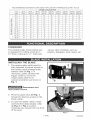
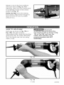
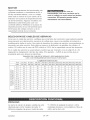
FOREWORD
The variable angle reciprocating saw
is designed for cutting wood up to
12" thick, metal up to 3/4" thick and
various other materials, such as
plastics, fiberglass, hard rubber, etc.
INSTALLING THE BLADE
1. The reciprocating shaft must be
fully extended to permit access to
the keyless quick-change blade
release collar (A) Fig. 1. If
necessary, gently squeeze the
trigger switch to move the
reciprocating shaft to its
outermost position (as shown in
Fig. 1).
Fig. I
Disconnect
from
power
teem
source,
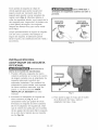
Pivot the guide shoe (B) Fig. 1,
forward to improve access to the
blade clamp.
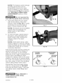
To open the blade clamp, rotate
and hold the blade retease collar
(A) Fig, 2 or Fig, 3 counterclockwise (as viewed from the front
of the saw).
Fig. 2
7- ENG
A03284
NOTE: The keytess quick-change
pivoting guide shoe can be
temporarily removed to make
blade installation easier. Release
locking lever (B) Fig. 3 to remove
(see PIVOTING GUIDE SHOE
ADJUSTMENT section of this
manual).
Do not operate the
roomwith the guide shoe removed.
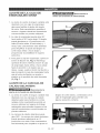
4. insert the blade into the clamp
until it hits bottom. Allow the
release collar (A) Fig. 3A to rotate
clockwise to lock the blade in
place. Close locking lever (B).
NOTE: The blade can be installed
upside down if preferred, for
better reach in tight fitting
applications.
Fig. 3
A
5. To remove blade, repeat steps 1
through 3, and pull blade from
blade clamp while holding the
release collar in the open
position.
NOTE: if the blade clamp collar
resists rotation to remove a blade,
work the blade up and down while
rotating the clamp (in a counterclockwise direction).
if the blade breaks leaving nothing to
grasp (to pull it from the clamp), it
may be necessary to use another
blade as a tool to aid in removing the
broken piece (see Fig. 4). While
holding the release collar in the open
position, use the tip of another blade
to "hook" the broken piece and pull it
from the clamp. (A thin, fine-toothed,
metal-cutting blade works best.)
Wear
A03284
ANSI
Fig. 3A
FLUSH
BREAK
RECESSED
BREAK
BROKEN
BLADE
Periodically clean the blade clamp
with dry compressed air. DO NOT
lubricate the blade clamp. Lubricant
can attract dust, metal filings and
debris.
safety glasses
while
compressed
air.
B
BROKEN
BLADE
Fig. 4
Z87,1
using
8- ENG
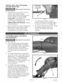
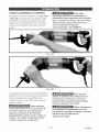
INSTALLING
THE OPTmONAL
BLADE ADAPTER
Disconnect
power
tool from
A'
source,
1, Standard jig saw blades may be
used in the vadabIe angle
reciprocating saw with the proper
blade adapter installed (sold
separately), To prepare for
installing a standard jig saw blade
follow steps 1 through 3 in
INSTALLING THE BLADE section
of this manual,
Fig, 5
(A)_Allow the release collar to
rotate clockwise to lock the blade
in place as shown in (A) Fig. 3A.
2, Insert the jig saw blade adapter (A)
Fig. 5 into the the clamp untiI it
hits bottom, Insert the jig saw
blade (B) into the blade adapter
3, To remove the jig saw blade, rotate
the blade release collar and
remove the blade and blade
adapter,
ROTATING GEAR HOUSING
ADJUSTMENT
Disconnect
tool from
power source,
1, The variable angIe reciprocating
saw is designed with a rotating
gear housing for easy adjustment
of cutting angle. This feature
permits access to places where
conventional tools cannot be
used,
Fig. 6
The gear housing can rotate 90 °
up or 90 ° down, The angle can be
adjusted to 13 detented positions
(6 up, 6 down, 1 straight),This
feature is designed to simplify
adjusting up or down angle of cut
and provide accessibility in
close quarters,
To rotate the gear housing,
depress lock button (A) Fig. 6,
Hotd the button depressed while
moving the gear housing up or
down to the desired position or
angle, Then reIease the lock
button and continue to move the
gear housing until the Iock button
snaps into the desired detent
position (B) Fig. 7,
Fig. 7
9- ENG
A03284
FRONT SCROLL HOUSING
ADJUSTMENT
Disconnect
power
A
tool from
source,
1. The variable angle reciprocating
saw is designed with a rotating
front scroll housing for easier
radius cuts. This feature permits
additional access in close
workspaces to reach places where
conventional tools cannot be
used.
The front scroll housing can
rotate 360°. The front scroll
housing can be adjusted radially
to 12 detented positions. This
feature is designed to simplify
adjusting to radial angle of cut and
combined with the rotating
gear housing, allows almost any
cutting operation.
To rotate the front scroll housing,
depress lock button (A) Fig, 8.
Hold the button depressed while
moving the front scroll housing
clockwise or counterclockwise to
the desired radial position or
angle. Then release the
lock button and continue to move
the front scroll housing until the
lock button snaps into the desired
detent position (B) Fig, 9.
Fig, 8
B
Fig. 9
PIVOTING GUIDE SHOE
ADJUSTMENT
Disconnect tool
from power
source,
DO NOT operate the
reciprocating
saw with the guide
shoe removed,
Fig. 10
The saw is supplied with a keyiess
quick-change guide shoe. The
pivoting guide shoe (A) Fig, f0, serves
as a rest while making a cut and it
can be adjusted to accommodate
many types of cutting applications.
To adjust, rotate lever (A) Fig, 11.
releasing the pivoting guide shoe (B).
Fig. 11
A03284
10-ENG
Adjust to one of the four positions
and close lever (A) Fig. 12. After
adjusting, make sure the locking lever
is completely closed in the locked
position (A) Fig. 12.
NOTE: DO NOT force the locking
lever closed. Adjust shoe enough to
allow the lever to lock in position
without force.
Fig. 12
HOW TO HOLD
SAW
Hold saw as shown in Fig. 13A or
Fig. 13Ba The gear housing,
intermediate plate, blade and pivoting
guide shoe may be made electrically
live if the blade cuts into live wiring
within a wail
To prevent
accidental electricaB shock the
tooB must be held as shown in Fig,
i3A or Fig.i3B, and have the
rubber front housing cover
properly installed and NOT
DAMAGED=
Fig. 13A
Fig, 13B
11- ENG
A03284
The rubber front housing cover also
serves as an assembly pin retention
mechanism. If the cover is removed or
becomes damaged the pins can fall
out.
Always exercise
extreme caution when positioning
hands, Use both hands to homd and
control toom especiammywhen
making angle or scroll cuts,
Exercise caution when cutting
towards operator.
Always be aware of
increased tool vibration, kickback
and blade breakage potential when
making angle and scroll cuts,
The handle (A) Fig, 14A can be
rotated 90 ° to the right or 90 ° and
180° to the left. To rotate handle,
depress locking lever (A) Fig, 14B and
rotate handle to the desired position.
After adjusting make sure handle is
locked in position before using the
saw.
NOTE: The handb WILL NOT rotate
360°
DO NOT use the
roomunless the rotating handle
is mocked in position, If the
handle will not lock, the toom
must be returned for repair.
Use only
recommended
blades with this tool
DO NOT use jig saw blades without
the proper bmade adapter.
Fig, 14A
Fig, 14B
A03284
12-ENG
TO START AND
STOP SAW
1.
Make sure power circuit voltage
is the same as shown on the
specification plate on the saw.
Connect saw to power circuit.
2+
Hold saw firmly (see Fig. 13A or
Fig.13B). Squeeze trigger switch
(A) Fig. 15, to start motor+
Release trigger to stop motor.
Fig. 15
VARIABLE
SPEED
The saw is equipped with a variable
speed control switch (A) Fig. 15 (0 to
2900 SPM). As the switch trigger is
squeezed, the speed of the saw blade
increases.
The lower speeds are recommended
for most metal cutting, while the
higher speeds are recommended for
wood. A few practice cuts at various
speeds (on scrap material), wilI aid
you in choosing the best speed for
obtaining the desired results on your
application.
BEFORE
YOU START
TO WORK
Select the blade best suited for the
material to be cut. For greatest
economy, use the shortest blade
suitable for the thickness of the
material to be cut.
Be sure the material to be cut is rigid.
Small work pieces should be securely
clamped in a bench vise or with
clamps to the work table. As the work
progresses in scrotl or curved cut-out
pieces, the material may be
readjusted to accommodate the
movement of the saw. The saw cuts
freely with only slight feed pressure.
Forcing the saw will not make it cut
faster.
SELECTING
THE BLADE
For best performance, longer blade
life, and smoother cut, select the
proper blade for the job. When cutting
metal always select a blade which wilI
allow at least three teeth to be
engaged in the thickness of material.
13= ENG
A03284
SAWmNG WOOD
PLUNGE
The variable angle reciprocating saw
is used much the same as a hand
saw in that it is moved toward the
operator during the cutting operation.
However, since the blade cuts on the
up-stroke instead of the down-stroke
as in the case of the hand saw, the
good or finish side of the work should
face down during the cutting
operation.
The variabte angle reciprocating saw
can be used for plunge cutting wood,
plywood, wallboard, and plastic
materials.
SAWING
pBunge cut metal
METAL
When cutting angle, H-beam, I-beam,
channel, etc. start the cut on the
surface where the greatest number of
teeth will contact the work. To make a
pocket cut, drilI a starting hole first. To
extend blade life, apply cutting oil to
the work suHace along the line of cut.
Clearly mark Iine of cut on the work.
Grasp front housing with one hand
and rear handle with the other hand.
Choose a convenient starting point
inside the line of cut in waste materia!
area. To start cut, rest saw on pivoting
guide shoe bracket, aiign blade with
the starting point, (blade NOT
touching work), as shown in Fig. 16.
Start saw. Using bracket as a pivot
point, roII saw forward by raising rear
handle, as shown in Fig° 17. When
blade has cut through the work,
continue raising the rear handle unti!
saw is perpendicular to the work and
guide shoe is fully seated on the work
surface as shown in Fig° 18. Keep
saw in this position and move blade
along line of cut.
Fig. 16
A03284
CUTS
14-ENG
Fig,17
Fig,18
15-ENG
A03284
KEEP TOOL
CLEAN
PeriodicatIy blow out aII air passages
with dry compressed air. All plastic
parts should be cleaned with a soft
damp cioth. NEVER use solvents to
clean plastic parts. They couId
possibly dissolve or otherwise
damage the material.
Wear ANSI Z87.1
safety glasses while using
compressed air.
LUBRICATION
This toot has been lubricated with a
sufficient amount of high grade
lubricant for the life of the unit under
normal operating conditions. No
further lubrication is necessary.
BRUSH
For your continued safety and
electrical protection, brush inspection
and replacement on this tool should
ONLY be performed by Sears Parts &
Repair Centers in the United States.
At approximately 100 hours of use,
take or send your toot to your nearest
Sears Parts & Repair Center in the
United States to be thoroughly
cleaned and inspected. And if
necessary, have worn parts replaced,
lubricated with fresh lubricant, new
brushes installed, and performance
tested.
Any Ioss of power before the above
maintenance check may indicate the
need for immediate servicing of your
tool. DO NOT continue to operate
too! under this condition. Return the
toot to a Sears Parts & Repair Center
in the United States for immediate
service.
A complete line of accessories is
available from your nearest Sears
store, Craftsman outlet, or through
the www.sears.com/craftsman
website.
A03284
INSPECTION
Since accessories
other than those offered by Sears
have not been tested with this
product, use of such accessories
coumd be hazardous. For safe
operation, use onJy accessories
sold by Sears.
16-ENG
SERVICE
AND
REPAmRS
All quality tools will eventually require
servicing or replacement of parts due
to wear from normal use. These
operations, including brush inspection
and replacement, should ONLY be
performed by Sears Parts & Repair
Centers in the United States. All
repairs made are fully guaranteed
against defective material and
workmanship. We cannot guarantee
repairs made or attempted by anyone
other than Sears.
For Sears replacement
1-800-4-MY-HOME@.
parts call
When servicing use
only identicam repmacement parts.
CAUSE
CORRECTION
Will not start
Switch, brushes or cord not
making good contact
Replace switch, brushes,
cord or electric outlet
Loss of power
Blown fuse or tripped
circuit breaker
Check for blown fuse or
17-ENG
open circuit breaker
A03284
Reciprocating
Saw Model
Number
353.28640
138
i05
133
SW[TCN
IPI II
__TR]GGER
II
]}LACK
120
VAC
_
_HITE
CDRI? LEA]]
WIRING
A03284
FZELD
WHITE LE4D
91AGRAM
18- ENG
180V
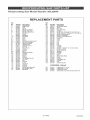
Reciprocating
Saw Model
Number
353.28640
REPLACEMENT
Ref,
No,
PARTS
Ref,
Part
No,
1
1A
2
3
3B
3C
4
5
11
11A
21
22
26
40A
52
53
57
66
67
68
69
70
81B
99
904514
878948
898676
874289
865323
865321
A03259
867853
855284
879009
902998
801852
879457
900669
n 886672
901162
911221
906717
908721
901476
A03260
908939
876053
694432
100
101
102
104
105
107
108
109
110
111
112
113
114
120
121
862704
863485
904513
879460
864696
897774
879442
882255
904443
803207
862189
862703
695077
802302
863095
_
No,
Part
ARMATURE
FAN
FIELD
BRUSH & SPRING
BRUSH HOLDER
BRUSH iNSULATOR
SWITCH
CORD
BEARING
BEARING
SEAL
SEAL
SEAL
RECiPROCATiNG
SHAFT
MOTOR
HOUSING
GEAR HOUStNG
HANDLE
SET
ROTATE
PLATE
SPRING
DEC
PLATE
LEVER
SCREW
BOLT
BEARING
MOUNT
122
123
126
127
128
129
130
131
132
133
134
135
136
136
139
140
141
142
143
144
145
146
147
148
844571
904512
900546
900547
900548
901073
901074
901165
906334
901455
901458
901459
901462
902052
901465
904644
901467
904415
901469
903164
901471
901472
901473
901474
RETAiNiNG
R_NG
GEAR
ROLLER
ROLLER CAGE
SCREW
GUIDE PiN, TORQUE TO 120-140
tN LB
GUIDE SLEEVE,
TORQUE
TO 17-23 iN LB
GEAR HOUSING
BOLT
SCROLL HOUSING
SCROLL HOUSING
BOOT
HOUSING
FOOT
YOKE
PiN
PiN
PiN
PiN
Q-RiNG
Q-R{NG
SCREW, TORQUE
TO 10 iN LB MAX
SCROLL LATCH
ROTATE
LATCH
SPR{NG
SPRING
SCREW
SCREW
SHOE
SPRING
RETAiNiNG
COLLAR
PiN
SCREW
PLATE
WASHER
SCREW
SCREW
MOUNTING
RETA{NtNG
BEARING
150
151
152
153
154
156
157
156
216
A03278
901717
901718
902362
875065
903351
904414
904326
843464
LEVER
CAM
RETAiNiNG
RiNG
RiNG
SCREW
CAM ADAPTER
Q-RiNG
CAP
STRAIN
REUEF
PiN K_T
No,
ACCESSORIES:
BRACKET
RiNG
230
231
233
234
19= ENG
875914
875667
A03281
900499
IOotionall
LUBR{CANT,
LUBRICANT,
CARRYING
UNIVERSAL
5 1/20Z
4 L5S
CASE
JtG SAW
BLADE
ADAPTER
A03284
A03284
2o-ENG
GARANTiA
TOTAL DE UN A_iO DEL CRAFTSMAN
PROFESSIONAL
TOOL
Si este Craftsman Profesional herramienta falla de dar la satisfacci6n
completa dentro de un a¢io de la fecha de la compra, LO VUELVE ALAS MAS
CERCANAS SEARS ALMACENA O QUEMA las PARTES & la REPARACION
CENTRAL EN LOS ESTADOS UNIDOS, y Sears Io repararan, Iibre de la carga.
Esta garanfia le otorga derechos especfficos y usted podr[a tener otros derechos que
var[an de un estado a otro.
Sears, Roebuck
and Co., Dept. 817WA, Roffrnan
Estates,
mL60179
NQmero de pieza ............................................................................. 353°28640
Tensi6n de alimentaci6n .................................................................... 120 Voltios
Consumo de energia ......................................................................... 1200 Vatios
Potencia de salida ..............................................................................
670 Vatios
Frecuencia ..................................................................................................
60 Hz
Carreras por minute ....................................................................... 0-2900 CPM
Gamas de trabajo (maximas)
Madera ..............................................................................................
30,5 cm
Metal .....................................................................................................
19 mm
Niveles con ponderaci6n A:
nivel de presiOn acOstica .................................................................... 88 dB
nivel de potencia acOstica .................................................................. 101 dB
Aceleraci6n media efectiva tipica .......................................................... 20 m/s 2
21=SP
A03284
Este manual contiene informaci6n que es importante para que usted sepa y comprenda.
Esta informaci6n se relaciona con la protecci6n de SU SEGURIDAD y la PREVENC!ON DE
PROBLEMAS AL EQUIPO. Para ayudarle a identificar esta informaci6n, utilizamos los
sfmbolos indicados mas abajo. Sfrvase leer el manual y prestar atenci6n a los mismos.
Indica una situaci6n de inminente riesgo, la cual, si no es evitada,
eausar_ la muerte o lesiones serias.
Indica una situaci6n potencialmente riesgosa, que si no es
evitada, podria resultar en la muerte o lesiones serias.
Indica una situaci6n potencialmente
peligrosa, la cual, si no es
evitada, podHa resultar en lesiones menores o mode°radas.
Usado sin el s[mbolo de seguridad de alerta indica una situa-ci6n
potencialmente riesgosa la que, si no es evitada, podria causar
da_os en la propiedad.
_L_'_'_'_'_'_
Algunos tipos de aserrin creados per mAquinas el_ctricas de lijado,
aserrado, amolado, perforado u otras actividades de la construcci6n,
contienen materiales qu[micos conocidos (en el Estado de California) como causantes de
cancer, defectos de nacimiento u otros da{ios del aparato reproductive. Algunos ejemplos de
dichos productos qdmicos son:
@
El plomo contenido
@
S[lice cristalizado
alba_ilerfa
en algunas pinturas con base de plomo
@
Ars6nico y creme provenientes
proveniente
de los ladrillos, el cemento y otros productos
del tratamiento
de
qufmico dado a la madera
con equipo de seguridad aprobado, use siempre protecci6n facial o respirador MSHA / MOSH
aprobados cuando deba utilizar dichas herramientas.
Lea y eomprenda
tedas
las siguientes
instrueeiones.
El no seguir las siguientes instrucciones puede resultar en un
cheque el_ctrico, en un incendio y/o en una herida personal.
GUARDE ESTAS INSTRUCCIONES
EL AREA DE TRABAJO
1.
2.
3.
Mantenga su espacio de trabajo limpio y bien iBuminado. Los bancos
desordenados y las Areas obscuras invitan las heridas.
No opere las herramientas
el_etricas en un ambiente explosive, come en la
presencia de los liquidos inflamabBes, los gases inflamables
o eBpolvo
inflamabBe. Las herramientas el6ctricas crean chispas que pueden encender el polvo
o los vapores.
No admita a los espeetadores,
a los ni_os ni a los visitantes euando se est_
operando una herramienta
eB_etriea. La distracci6n le puede causar perder el
control.
LA SEGURIDAD
1.
ELECTRICA
Las herramientas
con aislamiento
doble vienen con una clavija (enchufe)
polarizada (un eoneetor es m_s ancho que eB otto.) Esta cBavija se eoneetar_
a
un tomaeorriente
polarizado de una sela manera. Si madavija no entra bien en el
tomaeorriente,
invierta la elavija. Si todavia no entra, eomuniquese
con un
eBeetricista eualifieade papa que le instale un temaeorriente
polarizado. No
A03284
22- SP
cambie
la clavija de ninguna
manera.
El aislamiento doble []
elimina la necesidad
de tenet un cable de tres alambres y de tenet un sistema de potencia con conexi6n a
tierra.
2.
Evite el contacto
con las superficies
que tiene cone×i6n
a tierra
como la tuberia,
los radiadores, las estufas y los refrigeradores.
Si su cuerpo tiene una conexi6n a
tierra aumenta la posibilidad de que usted reciba un choque el6ctrico.
3.
No e×ponga la herramienta
el_ctrica a la Iluvia ni alas condiciones
mojadas. La
entrada del agua a la herramienta aumenta la posibilidad de que usted reciba un
cheque electrico.
4.
No maltrate eBcable. Nunca Ileve la herramienta per eRcable eR_ctrico ni Io
desconecte de un tir6n del tomacorriente.
No deje que el cable el_ctrico se
acerque a Io caBiente, al aceite ni alas superficies filosas. Mande reempBazar
inmediatamente
los cables eB6ctricos. Los cables electricos dadados aumentan la
posibilidad de que reciba un cheque electrico.
5.
Cuando use una herramienta
afuera, use un cabBe de servicio marcado con ,,W=
A_,o con ,,W_,. Estos cables estb.n fabricados para usarse afuera y reducen el riesgo
de un cheque el6ctrico.
LA SEGURmDAD PERSONAL
1.
Mant_ngase
16gicamente
cuando est_
memento de
en una grave
alerta; preste atenci6n a Io que est_ haciendo y proceda
cuando ope_e una herramienta
el6ctrica. No use la herramienta
cansado ni bajo la influencia de medicaci6n,
alcohol o drogas. Un
inatenci6n cuando est6 usando una herramienta el6ctrica puede resultar
herida personal.
2.
Wstase apropiadamente.
No Heve ropa suelta ni alhajas. Mantenga empelo largo
sujetado. Mantenga el pelo, la ropa y los guantes libres de las partes movibles,
La ropa suelta, las alhajas o el pelo largo puede engancharse en las partes movibles.
3.
Evite comenzar accidental
conectar. Las herramientas
Est_ que interruptor
seguro est_ apagado antes de
que Ilevan con el dedo en las herramientas de interruptor
o conectar que tienen el prende invita los accidentes.
4.
Quite [as Haves de ajuste y [as de tuerca antes de porter maherramienta
en
marcha. Una Ilave que se quede en una parte giratoria de la herramienta puede
causar una herida personal.
5.
No sobreamcance. Siempre mantenga buen equilibrio. El buen equilibrio ayuda a
controlar mejor la herramienta durante las situaciones inesperadas.
6.
Use Ice equipos de seguridad. Siempre use la protecci6n
de mos ojos. Tiene que
usar la mascara contra el polvo, el calzado antideslizante y/o el casco protector para
las condiciones apropiadas.
7.
Utimice el equipo certificado
de seguridad. El equipo de la visi6n debe conformarse
con est_ndares del ANSI Z87.1, el equipo el oft debe conformarse con est_ndares del
ANSI $3.19, y el equipo de respiraciSn debe conformarse con est_ndares certificados
MSHA/niosh del respirador.
8.
Nunca toque la broca inmediatamente
deepu_s
caliente aumentar_ el riesgo de una quemadura.
EL USO Y LA PROTECCK)N
1.
2.
del use. El contacto con una hoja
DE LA NERRAMIENTA
Use abrazaderas o de otra manera asegure y apoye la pieza en elaboraci6n
a una
plataforrna estabBe. El detener la pieza con la mano o contra el cuerpo no es estable
y puede causar la p6rdida de control.
No debe forzar la herramienta.
Use la herramienta
apropiada papa su apmicaci6n.
La herramienta apropiada har_ el trabajo mejor y con m_s seguridad a la velocidad
para la cual fue diseSada.
23- SP
A03284
3.
No use la herramienta si eBinterrupter no la pone en marcha o no la apaga. Una
herramienta que no se puede centrelar con el interrupter es peligresa y tiene que
repararse.
4.
5.
6.
7.
Desenchufe la herramienta
antes de ajustarla, de cambiaHe los accesorios
o de
guardaHa. Tales medidas de seguridad reducen el riesgo de un arranque accidental.
Guarde masherramientas
desocupadas
fuera deB aBeance de los niSos y de otras
personas no cuamificadas. Las herramientas son peligrosas en las manes del usuario
que no est6 cualificado.
Mantenga las herramientas
con cuidado. Mantenga los cuchiHos filosos y
lirnpios. Las herramientas que se cuiden adecuadamente y que tengan los cuchillos
filosos tienen menos tendencia de atascarse y son m_s f_ciles de controlar.
Verifique que no haya ningun desalinearniento
o atascamiento
de las partes
movibles, la rotura de partes u otra condiei6n que pueda afectar el
funcionamiento
de la herrarnienta. Si est_ daSada, rn&ndeBa componer antes de
usarla. Muchos accidentes son causados per las herramientas que no se mantienen
bien=
8.
Use s61o los accesorios
recomendados
per eBfabricante de su modelo. Los
accesorios que puedan ser adecuados para una herramienta pueden crear el riesgo
de herida cuando se usan con otra herramienta=
9.
UtHiee s61o aceesorios recomendados
para este instrumento
que son venalities
per Sears o una salida de Craftsman. El use de cualquier accesorio
compr5 puede ser en otra parte peligroso=
SERVlOlO
1. S61o las personas cualificadas para repararla pueden componer esta
herramienta.
El servicio o el mantenimiento hecho per las personas no cualificadas
puede resultar en el riesgo de herida.
2. Para mantener una herramienta,
use las partes de reemplazo id_nticas. Siga las
instruceiones
de la secci6n de Mantenirniento
de este manual El use de las
partes no autorizadas o el no seguir las Instrucciones
el riesgo de cheque o de herida.
de Mantenimiento
puede crear
1.
Detenga la herramienta
per las superficies aisladas para hacer una operaci6n
donde el cuchillo de Baherrarnienta pueda tocar un alarnbre escondido o su
propio cable. El contacto con un alambre cargado ,,vivo,, tambi6n cargarA alas partes
met_licas y le dar_ un cheque al usuario.
2.
Mantenga
seguridad.
las seguetas
3.
Mantenga
las manes fuera deB area de corte. Durante cortes, nunca trate de pasar
afiladas.
Las hojas afiladas harAn el trabajo mejor y con m_s
la mane per debajo o detras del trabajo per ninguna razon.
4.
ABterrninar un torte
inmediatamente.
tenga cuidado
de no tocar la segueta= Apague el motor
5.
Nunca sostenga la pieza en eBaboraci6n con la mane, en las rodillas ni contra
ninguna otra parte del cuerpo al aserrar. El vie puede resbalar y la hoja podda
contactar el cuerpo, causando la herida grave.
El ejercieio emcuidado extreme cuando ciega cortar. El
contacto de la hoja con objetos extranjeros alambre tal come el6ctrico, conducto, tubes
de instalaci6n de ca_er[as, etc. podrfa tener come resultado un riesgo del golpe o la
herida grave.
A03284
24- SP
7! '_'
° ='_5L!
ABgunasmaderascontienenpreservativosquepuedenser
t6xicos.
Tenga extrerna precauci6n para prevenir la inhalaci6n deB poRvo e eR
eontacte con la pier durante maelaboraci6n
de estos materialee, El polvo o los vaperes
de esta operaci6n poddan causar los problemas que respiran, irritaci6n de piel u otras
heridas.
Este instrumento
se dise_6 con toda seguridad
aplieaciones
eomo esos deserito en este manual El use inexacto de este instrumento podria tener
como la muerte de resultado o herida grave. No modifique ni utilice este instrumento para
ninguna aplicacion
para que no se disen6.
SiMBOLO
........................
........................
........................
........................
........................
........................
........................
........................
........................
........................
........................
........................
........................
DEFINmCK)N
voltio
amperios
hertzio
vatio (watts)
kilovatio (kilowatts)
microfaradios
litros
kilograma
neutonios por centimetro
Pascal
horas
minutos
segundos
........................
corriente altema
3 F'_
........................
corriente alterna de tres fases
3N f-'_*d
........................
corriente alterna de tres fases con neutral
........................
corriente continua (directa)
........................
velocidad sin carga
........................
corriente altema o continua
........................
Construcci6n
de Ctase ii
........................
construcci6n
a prueba de salpicaduras
........................
construcci6n
hermetica
........................
revoluciones
o carreras pot minuto
V
A
Hz
W
kW
#F
kg
N/cm _
Pa
h
rain
s
no
.../min
25- SP
cuadrado
A03284
MOTOR
Algunos herramientas de funcionar_n con
corriente continua o monof#_sica de 25 a
_No
use
su
herramienta con una corriente
60 Hz corriente altema y con un voltaje
en la
cual el voltaic no est6 entre los Rimites
correctos.
ERhaceHo puede dahar
seriamente su herramienta.
entre mas o menos el 5 per ciento de Io
indicado en la placa de especificaciones
de la herramienta. Algunos modelos son
dise_ados solamente para usar con
corriente alterna. Refi6rase a la placa de
especificaciones de su herramienta para
informarse del voltaje correcto y de la
capacidad normal de la corriente.
SELECCION
DE CABLES BE BERVlCIO
Si se usa un cable de servicio, verifique que el tama5o del conductor sea bastante grande
para prevenir una disminuci6n excesiva de voltaje que cause una p_rdida de potencia y
posiblemente dare el motor. Una gala de tamarios de cables de servicio recomendados se
encuentra en esta secci6n. Esta gala se basa en la limitaci6n de p6rdida de voltaje a 5
voltios (10 voltios en el case de 230 voltios) a 150% de la capacidad normal de amperios.
Si un cable de servicio se usar& afuera, tendr#_ que ser marcado con el sdijo W-A u W
siguiendo la designaci6n del tipo de cable. Per ejemplo - SJTW-A que indica que es
aceptable para use afuera (al aire libre).
TAMA(£1OS
DE CABLES DE SBqV_CIORECOMENDADOSPARA
use CON HERRAMIENTASELECTRICASPORTATILES
115V
230V
0-2
2-3
3-4
4-5
5-6
__ 68
is
18
12
18
18
8
8
6
6
_
8-10
18
14
12
10
8
8
6
6
4
10-12
12-14
14-16
16-18
18-20
16
16
16
14
14
14
12
12
12
12
10
10
10
8
8
8
8
8
8
6
8
6
6
6
6
6
6
6
4
4
6
6
4
4
4
4
4
4
2
2
4
2
2
2
2
_
o
b_._
E _
<--
Longitud deUcerd6n en pies
25 pies 50 pies 100 pies 150pies 200 pies 250pies 300pies 400 pies 500pies
50 pies 100pies 200 pies 300 pies 400 pies 500pies 600pies 800 pies 10% pies
18
18
18
16
16
14
14
12
12
18
18
16
14
14
12
12
10
10
18
18
16
14
12
12
10
10
8
18
18
14
12
12
10
10
8
8
18
16
14
12
10
10
8
8
6
PR6LOGO
La sierra
de vaivende _ngulovariable
de est_
s/4(I9ram)de pulgadade grosory otros
disdlada para cortar madera de hasta 12
materiales diversos, come pl#_sticos, fibra de
(305ram) pulgadas de grosor, metal de hasta
vidrio, goma dura, etc.
A03284
26- SP
PARA INSTALAR
LA SEGUETA
1. Hay que tenet el _rbol alternativo (eje de
vaiv_n) totalmente extendido para permitir
entrada al collar de seguridad de la
segueta (A) Fig. 1, quick-change. Si es
necesario, apriete ligeramente el gatillo
para mover el _rbol alternativo hasta su
posici6n extendida (como est_ ilustrado
en la Fig. 1).
Desconecte
la
Fig, 1
sierra de la fuente de e_ectricidad.
2. Gire la zapata de gufa (B) Fig. 1, hacia
adelante para aumentar la entrada al
seguro de segueta.
3. Rata abrir el seguro de segueta: gire y
sujete el collar de seguridad de la segueta
(A) Fig. 2 o Fig. 3 en el sentido
contrario alas manecillas del reloj
(mirando la sierra pot enfrente).
NOTA: La zapata de gala
giratoria quick-change puede quitarse
temporalmente para facilitar la instalaci6n
de la segueta. Suelte la palanca de
fijaci6n (B), Fig. 3, para quitar a la
izquierda (consulte la secci6n de este
manual Montaje y ajuste de la zapata de
gufa giratoria).
Fig. 2
No utHice la
herramienta
quitada.
con la zapata de guia
4. Meta la hoja en la abrazadera hasta que
golpee el fondo. Deje que el collar de
seguridad gire en el sentido de las
manecillas del reloj para asegurar la
segueta, (A) Fig. 3A. Cierre cerrando
palanca (B).
Fig, 3
NOTA: La segueta puede instalarse en
posiciOn invertida si se prefiere, para
tenet mejor alcance en aplicaciones en
espacios reducidos.
5. Para quitar hoja, repetir los pasos 1 por 3,
y tirar hoja de la abrazadera de hoja al
tenet el cuello de la liberaciSn en la
posicibn abierta.
NOTA: Si el collar del seguro resiste la
rotacibn para quitar la segueta, mueva la
B
segueta hacia arriba y hacia abajo
mientras gira el seguro en el sentido
contrario alas manecillas del reloj.
Fig, 3A
27- SP
A03284
Sisequiebra
lasegueta
sindejar
de
Ueve
ANSI
Z87.1
donde
agarrarla
para
poder
sacarla
del
anteojos
deseguridad
cuando
useairea
seguro,
puede
sernecesario
usar
otra
presi6n.
segueta
para
ayudar
asacar
elpedazo
de
quede
(yea
laFig.4).Mientras
detiene
el
collar
deseguridad
abierto,
uselapunta
dela
ROTURA
ROTURA
otrasegueta
para
'enganchar"
elpedazo
roto
PAREJA
ESCONDIDA
ytirelo
(jAlelo)
delseguro.
Una
segueta
SEGUET
SEGUETA
AROTA
ROTA
delgada
dedientes
finos
para
cortar
metal
sirve
mejor.
Limpie
peri6dicamente
elseguro
desegueta
conaire
seco
apresi6n.
NOlubrique
el
seguro
desegueta.
Ellubricante
puede
atraer
elpolvo,
lasclasificaciones
demetal
escombros.
Fig, 4
INSTALACI6N
ADAPTADOR
OPCIONAL
DEL
DE SEGUETA
Desconecte
_a
sierra de _a fuente de etectricidad.
1. Pueden utilizarse seguetas de sierra
caladora estandar en la sierra de vaiv6n
de _ngulo variable con el adaptador
segueta adecuado (vendido por
de
separado) instalado. Para realizar los
preparativos para instalar una segueta
de sierra caladora est_ndar, siga los
pasos 1 a 3 de la seccion PARA
INSTALAR LA SEGUETA de este
Fig, 5
manual
2. Introduzca el adaptador de segueta de
sierra caladora (A), Fig. 5, en la
3. Para quitar la giga vio hoja, gira el cuello
de la liberaci6n de hoja y quita el
adaptador de hoja y hoja.
abrazadera hasta que golpee el fondo.
Introduzca la segueta de sierra caladora
(B) en el adaptador de segueta (A). Deje
que el collarfn de suelta gire en el sentido
de las agujas del reloj para fijar la segueta
en su sitio de la manera que se muestra
en (A), Fig. 3A.
A03284
28-SP
AJUSTE DE LA CAJA DE
ENGRANAJES GJRAR
_
Desconectela
sierra de Jafuente de e_ectrieidad.
1, La sierra de vaiven de _ngulo variable est#_
diseBada con una caja de engranajes
girar para facilitar el ajuste del _ngulo
de corte, Esta caracteristica permite el
acceso a lugares donde las herramienta
convencionales no pueden utilizarse,
2, La caja de engranajes puede girar 90°
hacia arriba 6 90 ° hacia abajo, El #_ngulo
puede ajustarse en 13 posiciones con
ret6n (6 hacia arriba, 6 hacia abajo y 1
recta), Esta caracter[stica est_ diseriada
para simplificar el ajuste del #_ngulode
corte hacia arriba o hacia abajo y
Fig. 6
proporcionar accesibilidad en lugares
estrechos,
3, Para girar la caja de engranajes, optima el
bot6n de fijaci6n (A), Fig, 6, Mantenga
oprimido el bot6n mientras mueve la caja
de engranajes hacia arriba o hacia abajo
hasta la posici6n o el #_nguloque se
desee, Luego, suelte el bot6n de fijaci6n y
siga moviendo la caja de engranajes hasta
que el bot6n de fijaci6n se acople a
presi6n en la posici6n de retch deseada
(S), Fig. 7=
AJUSTE DE LA CARCASA DE
CALADO DELANTERA
Desconecte
Fig. 7
_a
sierra de _a fuente de eJectrieidad.
1= La sierra de vaiven de #_ngulovariable est#_
disenada con una carcasa de calado
delantera girar para facilitar los cortes
radiales= Esta caracterJstica permite un
_ngulo de corse radial y, combinada con la
caja de engranajes girar, permite casi
alguna operaci6n cortante=
acceso adicional en lugares de trabajo
restringidos para alcanzar lugares en los
que las herramientas convencionales no
pueden utilizarse=
2= La carcasa de calado delantera puede
girar 360 °=La carcasa de calado delantera
puede ajustarse radialmente en 12
posiciones con reten, Esta caracterJstica
est#_disehada para simplificar el ajuste al
Fig=8
29- SP
A03284
3.Para
girar
lacarcasa
decalado
delantera,
oprima
elbot6n
defijaci6n
(A),
Fig.8.
Mantenga
oprimido
elbot6n
mientras
mueve
lacarcasa
decalado
delantera
en
elsentido
delasagujas
delreloj
oen
sentido
contrario
aldelasagujas
delreloj
hasta
laposici6n
oel_ngulo
radial
quese
desee.
Luego,
suelte
elbot6n
defijaci6n
y
siga
moviendo
lacarcasa
decalado
delantera
hasta
queelbotOn
defijaci6n
se
acople
apresi6n
enlaposici6n
deret6n
deseada
(B),
Fig.9.
Fig, 9
EL AJUSTE GIRANDO ZAPATO
DE GUIA
Desconecte
_a
sierra de la fuente de electricidad.
RECIPROCATING
SAW sin instalar
la
zapata de gu_a.
La sierra son suministrados con un cambio
sin Ilaves de quick-change
girando zapato de
gu[a. La zapata (A) Fig. 10 siPve de apoyo
durante los cortes. Su movimiento giratorio
Fig. 10
permite la inclinaci6n gradual de la sierra
hasta Ilegar a la posici6n perpendicular
B
mientras se mueve hacia el operario.
Para ajustar, girar (A) Fig. 11 de palanca.
liberar el girando zapato (B) de gufa. Ajuste a
uno de las cuatro posiciones y cierre palanca
(A) Fig. 12. Despues que ajustar, se cerciora
la palanca que cierra es encerrada
completamente
posici6n.
el (A) Fig. 12 cerrado de la
Fig. 11
NOTA: NO fuerza la palanca que cierra
cerr6. Ajuste zapato para permitir bastante
que la palanca para cerrar en la posici6n
sin la fuerza.
Fig, 12
A03284
30-sP
COMO AGARRAR LA SIERRA
Para evitar
El asidero vio como mostrado en el Fig. 13A
o Fig. 13B. El engranaje que alberga, plato
intermedio, la hoja y gira zapato de gufa se
descargas el_ctricas accidentales, la
herramienta debe agarrarse de [a manera
puede hacer el_ctricamente vivo si la hoja
corta en el alambrado vivo dentro de una
que se muestra en _aFig. 13A 6 en _a Fig.
13B y tenet ia cubierta de goma de la
carcasa deiantera instaIada
pared.
adecuadamente
y NO DA_tADA.
Fig. 13A
Fig. 13B
La cubierta de goma de la carcasa delantera
tambi_n sirve como mecanismo de retenci6n
de los pasadores de ensamblaje. Si la
cubierta se quita o se daSa, los pasadores
pueden caerse=
atento a[ aumento de [a vibraci6n de [a
herramienta, el retroceso y _arotura
potencial de [a segueta cuando rea_ice
cortes en angulo y de ca[ado.
Utilice Qnicamente
suma precauci6n con [as posiciones de
[as manos. Use las dos manos para
agarrar y controIar [a herramienta,
especialmente cuando reaIice cortes en
[as seguetas recomendadas con esta
herramienta. NO uti[ice seguetas de sierra
ca[adora sin e[ adaptador
segueta adecuado.
de
angulo o de caiado. Tenga precaud6n
cuando eorte hacia e_ operador.
31- sP
A03284
Eldelasidero
(A)Fig.14Asepuede
girar
90° aladerecha
o90°y180
°ala
izquierda.
Para
girarelasidero,
deprimir
cerrando
depalanca
(A)Fig.14Bygirael
asidero
alaposici6n
deseada.
Despu6s
queajustar
secerciora
elasidero
secierra
enlaposici6n
antes
utilizar
elvio.
NOT,&:
Elasidero
nogirar_360 °.
No utHice el
instrumento
a menos que el asidero que
gire se cierra en la posici6n. Si el asidero
no cerrar_, el instrumento se debe vo_ver
para _areparaci6n.
Fig, 14A
A
Fig, 14B
PARA PONER
EN
PARAR LA SIERRA
MARCHA
Y
1, AsegOrese de que el voltaje del circuito
sea el mismo que el de la placa de
especificaciones en la sierra. Conecte la
sierra a la fuente de electricidad.
Agarre firmemente la sierra, (vea la Fig.
13A 6 Fig. 138). Apriete el gatillo
(interrupter) (A) Fig. 15, para poner el
motor en marcha. Suelte el gatillo para
parar el motor.
Fig. 15
A03284
32- SP
VELOCIDAD VARIABLE
PARA CORTAR METAL
La sierra est_ equipada con un interruptor de
control de velocidad variable (A), Fig. 15 (0 a
Para cortar hierro angular, viga H, viga I,
hierro de canal, etc,
empiece
pot la
2900 CPM). Tal como apriete el gatillo la
velocidad de la segueta aumenta.
superficie
donde el mayor nOmero de
dientes har_ contacto con el trabajo. Para
hacer un coke hundido (corte de bolsillo),
taladre un agujero primero. Para extender
Se recomiendan las velocidades bajas para
cortar la mayorfa de metales. Y se
hoja la vida, aplique cortando el petr61eo a
la superficie del trabajo conforme al corte.
recomiendan las altas para cortar madera.
Unos cokes de prueba usando varias
velocidades, le ayudar_n a escoger la mejor
velocidad para obtener los resultados
EL CORTE CLAVADO
deseados para el material que va a usar.
La sierra de vaiv_n de #_ngulovariable puede
utilizarse para realizar cortes clavados en
ANTES DE EMPEZAR EL
TRABAJO
madera, madera contrachapada, tablero
prensado para paredes y materiales de
plastico.
Seleccione la segueta mejor adecuada para
NO intente reaiizar
el material que va a cortar. Para mejor
econom[a, use la segueta m#_scorta que se
cortes c_avadoe en metal.
ajuste al espesor del material que va a cortar.
Marque claramente la Ifnea de corte en la
AsegOrese de que el material que va a coRar
pieza de trabajo. Agarre la carcasa delantera
con una mane y el aea trasera con la otra.
sea rfgido. Piezas pequdias en elaboraci6n
deben sujetarse bien con una prensa de
banco o con una abrazadera en la mesa de
Escoja un punto de inicio conveniente dentro
de la Ifnea de corte en el area de material de
desecho. Para comenzar el coke, apoye la
sierra en el soporte de la zapata y alinee la
trabajo. Mientras el trabajo de voluta (espiral)
o de cokes curvos progresa, el material
puede ser reajustado para acomodar el
movimiento de la sierra. La sierra corta bien
segueta con el punto de inicio (de modo que
la segueta NO toque la pieza de trabajo), de
coRar m_s r_pido.
la manera que se muestra en la Fig. 16.
Arranque la sierra. Utilizando el soporte come
PARA ESCOGER LA SEGUETA
punto de pivote, gire la sierra hacia adelante
subiendo el asa trasera, de la manera que se
Para el mejor rendimiento, una vida
muestra en la Fig, 17. Cuando la segueta
haya atravesado la pieza de trabajo, siga
con mfnima presi6n. Forz#_ndolano la har#_
prolongada de segueta y cortes mas finos,
escoja la segueta apropiada para el trabajo.
subiendo el asa trasera hasta que la sierra
est_ perpendicular a la pieza de trabajo y la
Para coRar metal, siempre escoja una
segueta que permita que por Io menos tres
dientes est6n en contacto con el metal a la
zapata de gufa est_ completamente asentada
en la supefficie de trabajo Fig. 18. Mantenga
la sierra en esta posiciOn y mueva la segueta
vez.
a Io largo de la I[nea de coke.
PARA CORTAR MADERA
La sierra de vaiv_n de Angulo variable se
utiliza prActicamente de la misma manera
que una sierra de mano en que es movida
hacia el operador durante la operaci6n de
corte. Sin embargo, como la hoja corta
durante la carrera ascendente en vez de
durante la descendente como los serrotes de
mano, el buen lado o lado acabado del
trabajo debe estar hacia abajo durante el
corte.
33- SP
A03284
Fig, 16
Fig, 17
Fig. 18
MANTENGA LA HERRAMIENTA
LIMPIA
Lteve ANSI
Z87°1 anteojos de seguridad cuando
use aire a presi6n°
Peri6dicamente sople todos los conductos
de ventilaci6n con aire seco a presi6n.
Quite la acumulaci6n de mugre que resulta
del trabajo con madera verde o Ilena de
savia. Todas las pares de pl_stico deben
ser limpiadas con una tela suave y
hOmeda. NUNCA use solventes para
limpiar las partes de pl_stico. Pueden
disolverlas o dadarlas de otra manera.
A03284
LUBRICACI6N
Este instrumento
se ha lubricado con una
cantidad suficiente de lubricante alto de
grade para la vida de la unidad bajo
operar normal las condiciones. Ninguna
lubricaci6n adicional es necesaria.
34-SP
JNSPECCJON
(Carbones}
DE ESCOBJLLAS
Para su seguridad continua y protecci6n
contra el cheque el6ctrico, la inspecci6n de
escobillas y cualquier reemplazo en esta
herramienta deben hacerse Sears Partes y
Centros de la Reparaci6n en los United
States.
Despu6s de aproximadamente 100 horas
de uso, Ileve o rnande su herramienta a la
Sears Partes y Centros de la Reparacion
en los United States. mAs cercana para
limpiarla a fondo y revisarla; para
reemplazar partes gastadas, cuando sea
necesario; para relubricarla de nuevo, si es
requerido; para reensamblarla con
escobillas nuevas; y para revisar su
rendimiento.
Cualquier p@dida de potencia antes de la
inspecci6n de arriba puede indicar que su
herramienta necesite servicio inmediato.
No continOe el use de la herramienta bajo
esta condici6n. Devuelva su herramienta a
la Sears Partes y Centros de la Reparaci6n
en los United States para obtener servicio
inmediato.
iiiiiiii_,
Una Ifnea completa de accesorios est_
disponible de su mAs cercana tienda de
Quemaduras, salida de Artesano, o per el
www.sears.eom/eraftsman
website.
iiiiiiiii,
Puesto que Ros
accesorios
con excepci6n de _sos
ofrecidos pot Sears no se hart probado
con este produeto, el use de tales
aecesorios pod#a set peligroso. Para la
operaci6n segura, eRuse s61o
aeeesorios vendidos per Sears.
SERVJCJO Y REPARACJONES
Toda herramienta de calidad
eventualmente necesitar_ servicio o
reemplazo de partes gastadas debido al
use normal. Estas operaciones, que
incluyen la inspecci6n y el reemplazo de
escobillas, deben hacerse Sears Partes y
Centros de la Reparaci6n en los United
States. Toda reparaci6n hecha por Sears
est#. completamente garantizada contra
Para el reemplazo de Sears despide la
Ilamada 1-800-4-MY-HOME ®,
Use
exelusivamente
refaceiones
euando reemplazo
id_ntieas
sea neeesario.
material y hechura defectuosa. No
podemos garantizar reparaciones hechas
o intentadas per ninguna otra agencia.
PROBLEMA
9o
empezara
La p6rdida del poder
CAUSA
El int'erruptor, los cepillos o
la cuerda no haciendo el
contacto bueno
CORRECCI6N
Reemplace interruptor, los
cepillos, la cuerda o salida
el6ctrica
El fusible soplado o el
cach6n tropezado del
circuito
Verifique para el fusible
soplado o abra cach6n de
circuito
35- SP
A03284
Your Home
For repair - in your home - of all major brand appliances,
lawn and garden equipment, or heating and cooling systems,
no matter who made it, no matter who sold it!
iiiiiii
iHHii
iHHii
iHHii
iHHii
iHHii
iHHii
iHHii
iiiiiiiiiiiiii
For the replacement parts, accessories and
owner's manuals that you need to do-it-yourself.
For Sears professional installation of home appliances
and items like garage door openers and water heaters.
1-800-4-MY-HOME
(1-800-469-4663)
www.sears.oom
(® Anytime, dayor night
(U.S.A.and Canada)
www.sears,ca
Our Home
For repair of carry-in products like vacuums, lawn equipment,
and electronics, call or go on-line for the nearest
Sears Parts and Repair Center.
1-800-488-1222
Anytime,day or night(U.S.A.only)
www,sears,com
To purchase a protection agreement (U.S.A.)
or maintenance agreement (Canada) on a product serviced by Sears:
1-800-827-6655
(U.S.A.)
Para pedir servicio de reparaci6n
1-800-361-6665
(Canada)
Au Canada pour service en frangais:
1-800-LE-FOYER Mc
(1-800-533-6937)
www.sears.ca
© Sears, Roebuck and Co,
(e) Registered
® Marca
_c Marque
Trademark
Registrada
/
TM
Trademark
/ TM Marca
de commerce
/ SMService
de Fabrica
/ MDMarque
/ SMMarca
d6pos_e
Mark of Sears,
de Servicio
de Sears,
Roebuck
Roebuck
de Sears,
and Co.
and Co.
Roebuck
and Co.