1
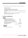
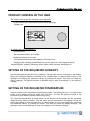
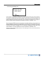
DRY PRECISION 100
Humidistat
User´s manual
CONTENTS
Product specification ............................................. 3
Technical parameters ............................................. 3
Product control by the user..................................... 4
Settings................................................................... 5
Service part: Product functions................................ 6
Parameters´ configuration....................................... 6
Description of configuration screens....................... 7
Switching unit.......................................................... 13
Power supply .......................................................... 14
2|
P roduct specification
This device provides a remote control of the dehumidifier. It has got the following functions:
-
Relative humidity measuring
−
Air temperature measuring
Requested humidity setting and the product´s switching on
Requested temperature setting and heating´s switching on
Radio frequency remote control of the dehumidifier with a backward monitoring of the
current status
Recording of the measured data in set time intervals and their saving in the internal
memory
Measured data transmission into the superior system by USB pen
Lightened LCD display with big numerals
−
−
−
−
−
−
TECHNICAL PARAMETERS
Control unit
−
−
−
−
−
−
−
−
−
Accuracy of relative humidity measuring
±1%
Accuracy of temperature measuring
± 1 °C
Adjustable correction of relative humidity display
± 99 %
Adjustable correction of temperature display
± 10 °C
Adjustable range of hysteresis of humidity switching
1-10 %
Adjustable range of hysteresis of temperature switching
1-10°C
Radio communication frequency
2,4GHz
Internal memory capacity
4096 (records)
Power supply
by 2 alkaline batteries
AA
Switching unit
−
−
−
3|
Power supply
Input
Max. current of switching elements
230 VAC
2 VA
3A
P roduct control by the user
PRODUCT CONTROL BY THE USER
The control unit has got the following control elements
−
−
Rotary wheels with confirmation function (when pressing)
Display unit
In a basic status the unit displays:
−
Air temperature
−
Set requested relative air humidity
−
Measured relative air humidity
−
Actual date and accurate time display in the bottom line
−
Displaying the following informational icons in the upper line: radio signal presence,
dehumidification, heating, defrosting, device failure, battery change indicating icon
SETTING OF THE REQUESTED HUMIDITY
Set the requested humidity by wheel revolution. The set value can be monitored on the display.
During the setting the lighting is switched on for a certain time. It is also possible to turn on the
lighting for monitoring the measured values, by pushing the wheel. This does not need any
setting changes. The lighting function is activated only in case of permitting it in the device´s
settings.
SETTING OF THE REQUESTED TEMPERATURE
Press the wheel in the requested humidity display mode. The lighting will turn on. During a time
period of the lighting press the wheel one more time. (In case the lighting function is not
permitted on your device, press the wheel only once.)
The requested temperature is shown down, on the left part of the display. Set the requested
temperature by wheel revolution. The set value can be monitored on the display. During the
setting the lighting is on for a certain time. It is also possible to turn on the lighting for monitoring
the measured values, by pushing the wheel. This does not need any setting changes. The
lighting function is activated only in case of permitting it in the device´s settings.
4|
Settings
DATE AND TIME SETTING
Press the wheel in the requested temperature display mode – the lighting will switch on. During
a time period of the lighting press the wheel one more time. (In case the lighting function is not
permitted on your device, press the wheel only once.)
The accurate time will be shown on the display by big numerals. By wheel revolution set hour
and then by pressing it confirm the setting. The setting of minutes, day, month, year and date is
done in a similar way.
After conforming the year by pressing the wheel you will return to the requested humidity display
mode.
SCREEN SAVER
After a certain time of inactivity the measuring unit turns off the display due to the batteries´
energy saving. Meanwhile the measuring and control functions stay active. If the screen saver is
active, there will be an arrow showing towards the wheel displayed for a short time and in
regular intervals, or the indicator located under the display blinks - depending on the set device
parameters.
It is possible to return to the basic state anytime by pressing the wheel.
The screen saver function is activated only in case of permitting in the device settings.
BATTERY CHANGE
The device will signalize a need of battery change by showing a discharged battery icon in the
upper part of the screen. In case the screen saver is switched on, this icon will blink
simultaneously with the arrow in the left part of the display or the indicator light of the saver will
blink twice.
Batteries – two alkaline pencilling batteries AA are accessible after the plastic cover removing.
Carefully remove the control wheel with a small, thin object (i.e. with a knife) in a following way:
Insert the knife under the wheel from the right hand side and then pull it toward yourself gently.
Grasp the plastic cover and by pulling the bottom part release it and then remove it. Change
the batteries by paying attention at the right polarity. Mount the cover. After the change set the
accurate time and date.
It is recommended to use lithium AA ,,Energizer Ultimate Lithium´´ batteries (sometimes
labelled as Energizer L91). These batteries last longer in comparison with the usual alkaline
batteries AA. The batteries are not accessible from another manufacturers, as Energizer
company has got a patent at its technology.
Lithium batteris Energizer Ulitimate Lithium
5|
Service part
PRODUCT FUNCTIONS
After inserting the batteries the welcome logo is displayed with a software version and the
equipment´s initialisation starts running. The first measuring and evaluation are performed.
Afterwards the equipment tries to make a radio connection with the switching unit. The time is
set on 12:00, date on 1.1.2009 and in case the connection is made, the first record with these
time details is registered. When performing backward monitoring it is possible to determine the
battery change realization.
The periodical recording of measured values and equipment status gets started. After making
the connection with the switching unit, the data are cyclically and in a set period transmitted into
the switching unit for recording. When the memory is full, the oldest data rewriting gets started.
It is not possible to delete the memory and it is either not possible to stop the recording – by this
the reliability of the equipment´s past status detection is ensured. Just before each record the
radio connection is made and the equipment status is detected.
After the period of measuring set in a ,,6´´ parameter has passed, the air humidity and temperature measuring is realized by an inbuilt sensor. Afterwards these data are evaluated. If it
is important to turn on/off the dehumidification, a radio signal is transmitted into the switching
unit.
In case of manual setting of the requested value the evaluation is also realized and if it is
important to intervene, the radio signal is sent.
In case of power cut of the switching unit, it is detected by the measuring unit only during the
next communication trial. After the power supply renewal, the switching unit´s status is activated
also only during the next communication trial. The time set in the ,,7´´ parameter (record period)
is the longest recovery time in case of constant operation. If the humidity or the requested
temperature gets changes, this time is shorter.
In case of power cut of the measuring unit, the switching unit detects its absence during the
parameter time 7 + 1 minutes. After this time the switching unit turns off the fan as well as the
compressor (if they were turned on before).
PAREMETERS´CONFIGURATION
For entering into the configuration menu, please keep the service button pressed and at the
same time press the control wheel. The service button is located under the display and is
accessible after removing the plastic cover.
For setting the requested parameter use the control wheel rotation.
Press the wheel for confirmation and continuing on the next configuration side.
6|
Service part
Description of configuration screens:
1. Service menu language
Service settings
1. Service menu
language
Slovak language
The menu´s language is chosen here. By wheel revolution choose the requested language
and then by pressing it confirm your setting. In case have not chosen any other languages,
by pressing the wheel you get into the next configuarion side.
2. Correction of relative humidity display
Service settings
2. Correction of RH
display
Measured:
55 %
-1 %
In this window it is possible to set the correction coefficient of relative humidity display. This
coefficient is simply added to the measured humidity. It is possible to monitor the corrected
measuring data in the button part.
3. Correction of temperature display
Service settings
2. Correction of
temperature display
2 °C
Measured:
25 °C
In this window it is possible to set the correction coefficient of temperature display. This
coefficient is simply added to the measured temperature. It is possible to monitor the
corrected measuring data in the button part.
7|
Service part
4. Hysteresis of dehumidification
Service settings
4. Hysteresis of
dehumidification
control
2 %
In this window it is possible to set the hysteresis of dehumidification switching, as this is a
two position regulation. The hysteresis field is always located right above the requested
value.
5. Heating hysteresis
Service settings
5. Hysteresis of
heating control
1 °C
In this window it is possible to set the hysteresis of heating switching, as this is a two position
regulation. The hysteresis field is always located right under the requested value.
6. Data measuring period
Service
6. Time interval of
data measuring
10
sec
This window provides a time interval setting between humidity and temperature measurings.
The less often setting saves battery energy but also prolongs the regulation cycle.
8|
Service part
7. Date recording period
Service settings
7. Time interval of
data recording
10
min
This window provides a time interval setting between the records. The less often setting
saves battery energy but also prolongs the regulation cycle.
8. Time of display lighting
Service settings
8. Time of display
lighting
3
sec
The lighting is activated by wheel rotation or pressing. During the time of inactiveness it is still
on until the time set in this window. The value must be adjusted to the lighting conditions at
the installation place. In case of sufficient external alight the lighting can be turned off totally.
By this the batteries´ longevity is considerably prolonged. In case of installing with the
network power supply, the lighting can be switched on permanently too.
9. Time until display turn off
Service settings
9. Time until display
turn off
20
sec
This window is for time setting, as long as the display is active. After this time has passed the
display switches to the saving mode with a considerably lower consumption.
9|
Service part
10. Period of life signs
Service settings
10. Period of life
signs
8
sec
.
In case of active screen saver there is an arrow icon with wheel shown on the display or the
LED diode blinks under it. The display/blinking period is set in this window.
11. Life signs
Service settings
11. Life signs
LCD
LED
Tu sa volí spôsob, akým zariadenie dáva najavo, že je v šetriacom móde.
The way of indicating the device´s presence in the saving mode is chosen here.
There are 4 possible variants
Turned off:
the screen saver is not used
LCD:
only the ,,Arrow with a wheel´´ icon is shown on the display
LED:
only LED diode blinks under the display
LCD + LED
The ,,Arrow with a wheel´´ icon is shown together with a LED diode blinking
12. Maximal humidity change per one measurement
Service settings
12. Max. RH change/1
measurement
3 %
In this window the device sensitivity to humidity changes can be reduced, by defining the
max. value by which the RH can be changed against the previous measurement. By this it
is possible to filter out the sudden humidity changes.
10 |
Service part
13. Receiving (switching) unit
Service settings
13.Receiving unit
00 07 B1 01
00 07 B1 A2
SEEK
-> FINISHED
In this window it is possible to allocate one or more switching units to the unit of measure.
The function is chosen by wheel revolution and arrow moving in up and down directions and
by pressing the wheel the function gets activated. After the first entry into this window, the
network addresses of switching units chosen yet are displayed. At this point it is possible to
leave the window without any parameter changes by choosing ,,FINISHED´´ item.
After choosing the SEEK function the searching for accessible switching units get started, the
network addresses of found units are displayed in the window. By moving the arrow to the
requested address and pressing the wheel, this unit can be chosen for receiving, by pressing
it once more the choice is cancelled. The unit choosing is signalized by a pipe next to the
network address. The chosen addresses must be confirmed by ,,FINISHED´´ item.
If there is not any network address chosen in the measuring unit, the unit will control the first
accessible switching unit.
11 |
14.Transmission minimizing
Service settings
14. Transission
minimizing
SWITCH ON
In here you can choose the mode in which the switching unit transmits only in case the
dehumidification is needed. By switching this mode on, the batteries´ longevity is prolonged,
however the data are periodically recorded only during the dehumidification being on.
12 |
Sw itching unit
SWITCHING UNIT
The switching unit status is directly displayed by LED diodes on the switching unit´s cover in
a following way.
green: power supply status and status of radio communication between
the equipments
−
constant shining: equipment under pressure, unsuccessful radio communication,
control unit out of operation or out of impact
−
blinking: equipment under pressure, successful radio communication
blue: dehumidification status. When shining, the fan relay is being switched on.
After a 4 minute layoff the compressor´s relay is switched on too.
yellow: heating status. When shining, the heating relay as well as the fan relay are
being switched on.
white: shining as yellow
defrosting status. The detector of ice coating on the evaporator reacted. Only
the fan operates.
red: shining as red
Status of compressor motor failure. The motor´s overheating sensor reacted. The
dehumidification part is laid off, only the heating part operates. The
dehumidification can start only after the motor´s cooling down.
DATA TRANSMISSION INTO THE MEMORY PEN
If you wish to transfer the measured and saved data for diagnosing the equipment operation,
please follow the following instructions:
−
Dismount the switching unit´s cover by releasing 4 screws
−
Insert the USB pen into the USB connector – the green LED diode blinks and the unit
identifies the USB pen. This status will last for cca. 5 seconds.
−
Only the white LED diode lights up – the data transmission starts
−
The green LED diode blinks– the date get saved in the pen
− The white LED diode lights up while the green LED diode with USB sign is alight
constantly – the transmission is finished
−
Pull out the USB pen from the equipment
−
Install the cover by 4 screws.
The data are saved in the pen in the ,,HYGRO.LOG´´ file and are divided from each other by
spaces. The first line is descriptive and the second one describes the fields. The rest of the
lines contents recordings – each record is in a new line. For further data processing it is
suitable to use a table processor. When loading there should be a ´´space ´´ set as a divider.
13 |
P ow er supply
POWER SUPPLY
The switching unit must be connected in accordance with the following description:
Clamper name
Function
L
Supply phase of the equipment and the
connected devices.
N
Working zero
FAN
Fan connection.
COMP
Connection of compressor´s contactor.
HEAT
Connection of electro valve for heating
control.
FROST
NTC sensor of ice coating.
OVHEAT
NTC sensor of compressor´s overheating.
COM
Common wire (conductor) of both NTC
sensors.
The switching unit is delivered with an installed resistor 1K between FROST and COM
clampers. This way it is prepared for operation without NTC heat sensors. In case of
sensors´ connection, it is necessary to disconnect the resistor.
Important warning:
Never disconnect the antenna from the receiver if the equipment is under pressure.
This may damage the receiver. Make sure that you always disconnect the energy supply first
when intending to disconnect the antenna.
14 |
CONTACT
www.microwell.eu
Company residence: Šaľa
ul. SNP 2018/42, 927 01 Šaľa
tel.: 031/702 0540-1
fax: 031/702 0542
mobile: 0903-413 764, 0902-422 422
e-mail: [email protected]
Branch office : Košice
Kováčska 28, 040 01 Košice
Tel./fax: 055/625 25 45
Mobile: 0911-454 010
e-mail: [email protected]
Please keep this user´s manual in a safe place so you will find it in case of need.
15 |