1
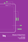
JAPAN
http://www.planex.co.jp
16PORT FAST ETHERNT SWITCHING HUB
E-mail: [email protected]
4F, Win Kanda Takahashi Bldg
1-7, Kanda Sudacho Chiyoda-Ku
Tokyo 101-0041 Japan
Tel: +81-3-3256-9091 Fax: +81-3-3256-9207
TAIWAN
http://www.planex.com.tw
E-mail: [email protected]
11F,No.190, Chung-Cheng Rd.,
Hsin-Tien, Taipei Hsien, Taiwan, R.O.C
Tel: +886-2-2910-0115 Fax: +886-2-2910-0116
ENW-8300-T/2T
FX-16NW
USERS MANUAL
16PORT FAST ETHERNT SWITCHING HUB
FX-16NW
Trademarks
Copyright @1999 PLANEX COMMUNICATIONS INC.
Contents subject to change without prior notice.
Pci is a registered trademark of PLANEX COMMUNICATIONS INC.
All other trademarks belong to their respective proprietors.
● Do
not use extra/optional attachments unless their use is recommended by
the product manufacturer. Doing so may cause hazards.
● Do
not use this product near water.
● Do
not place this product on an unstable cart, stand or table as the product
may fall, harming people as well as the appliance itself. When mounting
the product to a wall or shelf, be sure to follow the manufacturer’s
instructions. You may only use a mounting kit approved by the
Copyright Statement
No part of this publication may be reproduced in any form or by any means
or used to make any derivative such as translation, transformation, or
manufacturer.
● Slots
adaptation without permission from PLANEX COMUNICATIONS INC.
and openings on the back or bottom of the cabinet are provided for
ventilation to insure reliable operation of the product. The openings must
FCC Warning
a bed, sofa, rug or any other similar surface. The product should never be
This equipment has been tested and found to comply with the limits for a
placed near or over a radiator or heat register. Similarly, this product must
not be placed in a built-in installation such as a bookcase unless proper
not be blocked as it may cause overheating. Do not place this product on
Class A digital device, pursuant to Part 15 of the FCC Rules. These limits
ventilation is provided.
are designed to provide reasonable protection against harmful interference
when the equipment is operated in a commercial environment. This
equipment generates, uses, and can radiate radio frequency energy and, if
not installed and used in accordance with this user’s guide, may cause
harmful interference to radio communications. Operation of this equipment
in a residential area is likely to cause harmful interference in which case the
user will be required to correct the interference at his own expense.
CE Mark Warning
This is a Class A product. In a domestic environment, this product may
cause radio interference in which case the user may be required to take
adequate measures.
Safety Instruction
●Unplug
this product from the wall outlet before cleaning. Do not use
liquid or cleaners or aerosol cleaners. Use a damp cloth for cleaning.
●
This product should be used only with the appropriate power source
indicated on the marking label. If you are not sure which type of power is
supplied at your home, please consult your dealer or an electric power
company.
● For
added protection, turn off and unplug the product from the wall outlet
whenever it is left unattended or unused for a long period of time. This
will prevent damage to the product due to power surges.
not overload wall outlets or extension cords as this may result in a
● Do
short circuit or fire.
● Do
not attempt to insert any object via openings on the cabinet as it may
cause a serious electric shock or fire. Never spill a liquid of any kind on
the product.
● Under any of the following conditions, promptly unplug the product from
the wall outlet and seek assistance from a qualified service center.
About this Manual
a. The power cord or AC power adapter is damaged (or frayed).
b. If liquid has been spilled into this product.
c. The product does not operate normally even though you followed
appropriate operating instructions. Adjust only those controls that are
covered by the operating instructions as improper adjustment of
othercontrols may result in damage and will often require extensive work
by a qualified serviceperson.
Be sure to read this chapter first
Chapter 1
Introduction
Describes the Switch and its features, Please be certain to read this chapter before installing the Switch.
d. The product has been dropped or the cabinet has been damaged.
e. When this product exhibits a distinct change in performance, indicating a
need of repair.
● When
replacement parts are required, be sure to obtain parts specified by
the manufacturer. Unauthorized substitutions may result in fire, electric
Chapter 2
Hardware Installation
Helps you to get started with the basic installation of the Switch and explains how to
connect the FX-16NW to your Ethernet network.
shock or other hazards.
Chapter 3
Configuring the Switch From a Console
Describes how to configure the VLAN, Trunk, Spanning Tree and Port Mirroring features
of the Switch using a console (PC). The FX-16NW Fast Ethernet Switching Hub can be
also used as an ordinary switching hub. Please read this chapter when you need to enable
the VLAN and Trunk features of the Switch.
Appendix
Appendix A
Appendix B
Troubleshooting
About Auto-Negotiation
Appendix C
About Spanning Tree Protocol
Appendix D
Specifications.Lists the technical (general, physical, environmental as well as performancerelated) specifications of the switching hub.
Version:1.0 E Rev.A
FX-16NW
Chapter 1
1 - 1
2
3
4
5
6
7
8
9
Introduction
P roduct Overview .......................................... 1
F e a t u res ........................................................... 2
Packing List .................................................... 3
P a rts Terminology ......................................... 3
Front Panel ..................................................... 5
Rear Panel ........................................................ 5
Bottom Vi e w .................................................... 5
Switching Technology1-6 Flow Control
............................................................................. 6
About VLAN ................................................... 8
VLAN ................................................................ 9
Trunking Technology ................................... 12
P o rt Mirroring ............................................... 13
Chapter 2 Installation
2 - 1 E n v i ronmental Require m e n ts .................... 15
2 Installing the Switching Hub .....................15
3 Connecting the Supplied Power Cable to
the Switch ....................................................... 1 6
4 Connecting Computers to the Switch
............................................................................ 1 6
5 Cascading to an Additional Hub or a
Switch .............................................................. 1 7
6 Connecting a PC to the Console Port
............................................................................ 1 9
FX-16NW
Chapter 3 Configuring the Switch From a
Console
3 - 1 Main Menu ..................................................... 2 1
2 Configuring the Switch Settings .............. 2 2
3 Configuring the Spanning Tree Settings
............................................................................ 25
4 Displaying the Spanning Tree Settings
............................................................................ 28
5 Configuring the Port Mirroring Settings
............................................................................ 29
6 Configuring the Trunk Port Settings
7
8
9
10
............................................................................ 31
Configuring the VLAN Group Settings
............................................................................ 33
Resetting the Switching Hub
............................................................................ 38
Resetting the Default Settings
............................................................................ 39
Quitting the Main Menu ............................ 39
Appendix A
Tr o u b l e s h o o t i n g ............................................. 4 1
Appendix B
About Auto-negotiation ............................... 4 3
Appendix C
About Spanning Tree Protocol ................... 4 5
Appendix D
S p e c i f i c a t i o n s ......................................... 5 1
Introduction
FX-16NW
1
1
Product Overview
The FX-16NW 16 Port Fast Ethernet Switching Hub features sixteen
10/100BASE-TX auto-negotiation switch ports. The Switch is rackmountable, and fully supports IEEE 802.3 10BASE-T and IEEE 802.3u
100BASE-TX standards. All of the 16 STP ports support RJ-45 twistedpair cables, and the Auto-Negotiation feature automatically detects the
appropriate data transfer speed (10/100Mbps) as well as the duplex mode
(full/half duplex). Each port is also equipped with LED indicators that
display the latest status of the hub and the network.
The FX-16NW Switching Hub supports the VLAN and Trunking features.
One or more ports can make up one VLAN group, and the user may utilize
up to sixteen of such VLAN groups in the Switch. Thanks to the Trunking
technology, the Switch achieves a data transfer speed of up to 800Mbps
when linked to another hub with Trunking support. Four ports are
“bundled” into one high-throughput “trunk” to achieve this speed.
Furthermore, the Switch supports Spanning Tree Protocol that provides
redundancy to the entire network.
※The
Switch does not support Trunking connection to devices other than
FX-16NW.
To ensure maximum safety and good performance, please read carefully and
follow all the directions in this manual. It is assumed that you have some
basic understanding of Local Area Networking (LAN) concepts as bridging,
IEEE802.3 10BASE-T Ethernet, and IEEE802.3u 100BASE-TX Fast
Ethernet.
1
FX-16NW
1
2
Features
FX-16NW
1
Packing List
3
Provides 16 RJ-45 STP ports for 100BASE-TX/ 10BASE-T connection
Open the shipping carton of the Switching Hub and carefully unpack its
Complies with IEEE802.3 Ethernet and IEEE802.3u Fast Ethernet
standards
contents. The carton should contain the following items:
Fully supports Auto-Negotiation: automatically detects the transfer speed
FX-16NW x 1
(100/10Mbps) and duplex mode (half/full-duplex)
Serial Cable x 1
Supports Store & Forward switching scheme
Power Cord x 1
Metal Fittings and screws for rack mounting
Equipped with a MAC address table: automatically learns up to 16,000
MAC addresses
Equipped with a 4MB packet buffer
Supports up to 16 VLAN groups
Supports Trunking: enables 800Mbps high speed communication between
two FX-16NW units
Complies with Spanning Tree Protocol
Provides Port Mirroring function for analyzing packets
Transfer speed (100/10Mbps) and transfer mode (full/half-duplex) can be
configured manually as well
Rubber feet with adhesive backing
This User’s Manual
If any item is found missing or damaged, please contact your local PCI
reseller for replacement.
1
4
Parts Terminology
Front Panel
Flow Control Supported (full-duplex: IEEE802.3x, half-duplex: Back
Pressure)
LED indicators for monitoring the status of each port and the network
1-1 Front Panel
Provides one uplink port for cascading to another hub
Mountable to 19-inch racks
Equipped with one serial port for configuring VLAN and other settings
2
3
FX-16NW
< Port 1-16 >
FX-16NW
Rear Panel
RJ-45 ports for 100BASE-TX/ 10BASE-T twisted-pair cable connection.
< Uplink Switch >
When the switch is pressed down, Port 12 operates as an uplink port.
1-2 Rear Panel
< Reset Switch >
Console Port : Connects to the supplied serial cable. The cable is in turn
Used to reset the FX-16NW Switching Hub. When this switch is pressed
attached to a terminal(PC) for configuring the switch.
down, all the parameters are reset to their initial (power-up) states.
Power Connector : Connects to the supplied power cable.
Power Switch : Turns on/off the power of the switch.
< Power LED >
This LED lights when the power of the FX-16NW is turned on.
Bottom Side
< Link/Act LED >
This LED illuminates when there is a valid data link on the port. The LED
blinks during data transmission/reception.
< 100M LED >
The LED is turned on when a 100Mbps link is established on the port.
< FDX LED >
The LED illuminates when there is a full-duplex link is established on the
port.
1-3 Bottom Side
< Col. LED >
The sticker below is attached on the bottom side of the Switch.
The LED flashes whenever a collision occurs on the network.
< Model Name >
The product model name of the switching hub.
< Serial No >
A unique product serial number is assigned to each switching hub unit.
Please be sure to include this information in your user registration form.
4
5
FX-16NW
1
5
Switching Technology
FX-16NW
Switching scheme
Most switching hubs support one of the following switching schemes: Cut
This number is also required for all technical support services.
Through or Store & Forward. In Cut Through switching, any received
Ordinary repeater hubs transmit data to all ports, even when only one port
packet is sent to one of the ports immediately after its destination address is
discerned. Since packets themselves are not inspected, some error packets
needs the data. Consequently, the overall network traffic increases, slowing
may leave the switch among normal packets. In contrast, Store & Forward
down communications on the network itself. Moreover, repeater hubs
require that all ports share the same bandwidth; a collision occurs when
checks for length and CRC. Error packets are dropped at this stage, and
multiple packets are transmitted simultaneously. To counter these problems,
only normal packets are transmitted. The FX-16NW Switching Hub
supports the Store & Forward switching scheme.
How Switching Hubs differ from Repeater Hubs
the switching hub learns the destination address and sends data only to the
port that leads to the destination node. This scheme prevents the data from
being sent to other ports, thereby reducing network load. A switching hub
thus allows more efficient communication among computers on the
network.
technology first stores the received packet in an internal packet buffer and
Resets the Limitations on Cascading Hubs
Generally, repeater hubs can cascade only up to four stages for 10BASE-T
and two stages for 100BASE-TX. This limitation does not apply to a
switching hub because each port on the switch has its own collision domain.
For this reason, switching hubs can expand an existing network without
using relatively more expensive routers or bridges.
Figure 1-4
6
7
FX-16NW
1
6
About Flow Control
FX-16NW
1
7
VLAN
The Switching Hub also supports Flow Control technology for preventing
The VLAN feature of the Switching Hub lightens traffic on a network and
packets from overflowing the packet buffer. The flow control technology
used in half-duplex mode is called “Back Pressure”, while the flow control
strengthens network security, all by dividing the original broadcast domain
into smaller groups; ports on the Switch are divided and grouped into
scheme used in full-duplex operation is called “IEEE 802.3x”. In Back
several VLAN groups. Each VLAN group acts as a separate small domain,
Pressure, a collision signal is sent out whenever the packet buffer becomes
and packets being sent in one VLAN group (including broadcast packets)
full. On the other hand, a switching hub with IEEE 802.3x support transmits
are not transmitted to other VLAN groups. This feature gives the following
a “pause” command to the source node to stop the data flow itself. To
utilize IEEE802.3x flow control, the attached network card must also
advantages to the Switch over other switching hub products:
support IEEE802.3x flow control. (Currently, most of the network cards on
Improved Networking Efficiency
the market do not support this feature. PCI’s FNW-9800-T Fast Ethernet
By separating nodes in a high-traffic work group into multiple smaller
adapter card complies with IEEE802.3x flow control ahead of other
vendors.)
groups, the existing broadcast domain is divided into smaller domains and
prevents packets from being sent to other (small) workgroups. Since
unnecessary data transmission to other workgroups is cut, networking
If either the switch or network interface card does not support flow control,
efficiency over the entire network improves considerably.
the source device (PC) will continue to send packets to the switch even
when its packet buffer is full. As a result, packets received by the switch
will overflow and those overflowed packets are lost. Upper layer protocols
Enhances Security
Network communication among VLAN groups is logically disabled.
handle the lost packets, and TCP/IP (as one of the protocols) requests the
Therefore, confidential documents or data can be contained in one specific
PC to resend the packets. Since packet overflow itself at the switch persists,
VLAN group of users who are authorized to handle the information.
PCs will be forced to consume extra system resources by sending packets
again and again even though most of the packets are lost continuously.
Cost Reduction
With the VLAN support, the Switch can create multiple domains all by
8
9
FX-16NW
FX-16NW
Each of the sixteen switch ports on the FX-16NW Switching Hub can be
Although a collision domain is divided by each of the ports on the Switch, a
assigned to multiple VLAN groups, and up to 16 groups can be created in
broadcast packet is still sent to all ports, regardless of collision domain
the Switch. For a specific procedure to assign each port to a VLAN, please
refer to Chapter 3.
differences. The portion of a network that receives a broadcast packet is
called a “broadcast domain”. Normally, a router is used to divide one
itself; there is no need to obtain expensive routers to do the job.
Broadcast Domain
broadcast domain into multiple domains.
Figure 1-5
Broadcast Packet
This is the packet that is received by all devices on a network. VLAN and
routers can modify how this packet is sent to nodes in a given network.
Collision Domain
Figure 1-6
In a network that employs repeater hubs, a collision of packets may take
place when two or more devices on the network transmit a packet at the
same time. The portion of a network that shares the same collision signal is
called a “collision domain”. In a switching hub, each port is assigned to a
separate collision domain. (In other words, a collision domain is divided
into multiple smaller collision domains.) In addition, certain limitations on
node-to-node distance and cascade connection apply to nodes within the
same collision domain.
10
11
FX-16NW
1
8
Trunking Technology
FX-16NW
Note :
Be sure to match ports in a Trunk in increasing order.
By bundling four ports into one high-throughput trunk, the Tr u n k i n g
Example :
technology allows two units of FX-16NW to communicate at 800Mbps
Port 1 through 4 in Trunk 1 of Hub A need to be linked to ports with the
same number in Trunk 1 of Hub B.
maximum (full-duplex 200Mbps x 4). The high-throughput trunk(s) can
boost the data transfer speed between hubs in a cascade connection.
Hub A Trunk 1 (Port 1,2,3,4) <-> Hub B Trunk 1 (Port 1,2,3,4)
For a specific procedure to configure the Trunking function, please refer to
—> Matching order: 1-1, 2-2, 3-3, 4-4
Chapter 3.
Note:
※The
Switching Hub only supports a trunking connection with antoher FX-
16NW; it cannot be trunked to other devices with Trunking support.
Even though four ports are assigned to a trunk, only some of them may be
actually in use if less than four devices are attached to the Switch. For
instance, only two out of the four ports will be used if Hub A and Hub B in
the example above has only one device attached.
1
9
Port Mirroring
When Port Mirroring feature of the Switching Hub is enabled, the traffic on
a given port is copied to another port that is attached to a LAN analyzer or
similar device.
For instance, a traffic between Port 1 and Port 2 on a traditional switch does
not basically flow to another port. For this reason, both a LAN analyzer and
Figure 1-7
devices such as repeater hubs are required to inspect the traffic between the
The Switching Hub supports three types of Trunk settings. To connect two
two ports. With FX-16NW, the extra devices are no longer required.
FX-16NWs via a trunk, both units need to be configured in the same
Simply enable the Port Mirroring feature and attach a LAN analyzer such as
Sniffer to the destination port- you can analyze the traffic without using
manner.
other devices, swiftly narrowing down the scope of possible causes of port
malfunction.
12
13
Chapter 2
Installation
FX-16NW
2
1
Environmental Requirements
Before proceeding, please take a minute to review the safety guidelines
described in the Safety Instructions above. Also, be sure to follow the
additional guidelines below.
Do not place the product in a damp or wet location.
Always avoid dust and dirt.
Do not install the product in an area exposed to direct sunlight.
Allow some space between the product and the surroundings to facilitate
dissipation of heat generated inside the hub.
Figure 1-8
Warning:
An accumulation of dust or dirt on the sides of the product or in the air
Equipped with these advanced features, switching hubs can provide much
greater network traffic efficiency and expandability compared to ordinary
repeater hubs.
vents on the rear panel may prevent sufficient heat dissipation. Periodically
inspect these sections of the product and remove any dirt by a vacuum
cleaner, etc.
2
2
Installing the Switching Hub
Always place the product on a level surface (ex. desktop) or in a standard
19”rack.
Installing the Switch on a Level Surface
1. Attach the supplied rubber feet (4 pcs) to the base of the switching hub.
2. Place the product on a level surface such as desktop.
14
15
FX-16NW
FX-16NW
Installing the Switch in a 19” Rack
1. Use the supplied screws to attach the metal fittings to the switching hub.
2. Use the screws for the rack to mount the switching hub to your rack.
2
3
Connecting the Supplied Power Cable to the Switch
1. Attach the supplied power cable to power connector on the rear panel.
2. Connect the other end of the power cable to a 100V wall outlet.
Figure 2-1
3. Verify that the Power LED on the front panel is turned on.
Note :
2
4
Connecting Computers to the Switch
1. Install a 10BASE-T/ 100BASE-TX network adapter card and driver in
each computer you want to network.
2. Prepare a twisted-pair cable with RJ-45 plugs at both ends. Cable length
should not exceed 100 meters (328 feet), and cable type must be Category
5 if you are using 100BASE-TX network card. If the network card is for
Before connecting any device to Port 12, please make sure that the
Uplink/Normal switch (located right next to Port 12) is set to OFF. If the
switch is depressed, it means it is ON.
Be sure to use Category 5 UTP cables for 100BASE-TX connection.
Similarly, use Category 3 (or greater) cables for 10BASE-T connection.
The maximum cable length is 100 meters.
Should you experience any problem in establishing a data link on any of
10Mbps connection, you may use Category 3, 4 or 5. A variety of
Category 5 network cable products are available from PCI (UTP-xx-05,
the ports, please refer to Appendix A and Appendix B.
UTP-xx-DT, STP-xx-05).
2
5
Cascading to an Additional Hub or a Switch
3.Attach one end of the cable to the RJ-45 port on the computer’s network
adapter, and the other end to any of Port 1-16 of the Switching Hub.
Using the hub in a stand-alone configuration, you can network up to
You can “daisy-chain” or cascade the FX-16NW to another Hub or Switch
to use additional ports (nodes).
sixteen computers.
1. Prepare a straight-through cable with RJ-45 plugs. Å@If you are only
4. The Link LED of each port will be turned on if a valid link is established.
using 100BASE-TX devices, please make sure to use a Category 5 cable.
A variety of Category 5 network cable products are available from PCI
(UTP-xx-05, UTP-xx-DT, STP-xx-05).
2. Press the Uplink/Normal switch down.
3. Connect one end of the cable to the uplink port (Port 12) on the FX16NW.
16
17
FX-16NW
4. Connect the other end of the cable to a port on the other device.
5. The Link LED of the port will be turned on when a valid link is
established.
FX-16NW
Note:
Should you experience any problem in establishing a data link on any of
the ports, please refer to Appendix A and B for troubleshooting.
6. To cascade more than two hubs to the FX-16NW, connect the uplink port
on the other hub to one of the ports (excluding the uplink port) on the
FX-16NW. If the other hub is not equipped with an uplink port, use a
Be sure to use Category 5 UTP cables for 100BASE-TX connection.
Similarly, use Category 3 (or greater) cables for 10BASE-T connection.
The maximum cable length is 100 meters.
crossover cable to connect the two hubs.
2
6
Connecting a PC to the Console Port
The administrator can attach a PC to the serial console interface (RS-232
port) on the switching hub to configure and alter the default settings of
VLAN, Trunking, Spanning Tree Protocol as well as Port Mirroring features
of the product. This port is a DCE (data communication equipment) port
that utilizes a female DB-9 connector. A PC preinstalled with a terminal
utility is required to use the console port.
Figure 2-2
1. Configure your terminal utility in the following manner
About Uplink port
An uplink port is used to connect to an additional hub, and its wires are
cross-linked inside the hub. If you are using Port 12 as an uplink port, be
Check each of the four parameters and change the value if necessary.
Baud Rate: 19,200 (default setting)
sure to turn on (press down) the Uplink/Normal switch that is located right
Parity: None
next to Port 12. The following table shows valid port/ cable type
8 Data Bit
combinations
1 Stop Bit
FX-16NW
Uplink Port
18
Cable Type
The Other Hub
Straight
RJ-45 Port
Uplink Port
RJ-45 Port
Straight
RJ-45 Port
Crossover
RJ-45 Port
Uplink Port
Crossover
Uplink Port
19
FX-16NW
2. Attach the supplied serial cable to the switch and PC The product comes
Configuring the Switch From a Console
All the parameters and operational settings of VLAN, Trunking, Spanning
with a straight RS232 cable with DB-9 male connectors. Please check
Tree and Port Mirroring features are configured through a terminal
whether or not your PC is equipped with a DB-9 male connector. (Most
application. This chapter describes the configuration procedure for each of
of computers support a DB-9 male connector.)
these four features. To learn how to connect a PC (installed with a terminal
application) to the console port on the Switching Hub, please refer to
Section 2-6.
3
1
Main Menu
Once the console port and the terminal are configured properly and a valid
link is established between the two, the following setup menu is displayed.
This menu is the root or starting point of the entire configuration submenus.
Enter the number corresponding to the feature you wish to configure, and
press the Enter key.
Figure 2-3
20
21
FX-16NW
3
2
Configuring the Switch
FX-16NW
The transfer mode of the port can be set to any of the following modes:
[1]Auto [2]100Full [3]100Half [4]10Full [5]10Half
[1] Config Switch Setting
Type the desired mode number after the [New Media Mode>] prompt and
In this menu, you can specify the data transfer mode(speed), Flow Control
options and the Aging Time for each of the 16 ports. Type “1” after the
press Enter.
[Setup>] prompt, and press Enter. The following menu will be displayed:
Now, you can enable or disable the Flow Control feature. Enter “y” after
the [New Flow Control Mode>] prompt if you wish to enable Flow Control,
or enter “n” to disable this feature. Then press Enter to continue.
[1] Set Port Condition
This option specifies the data transfer mode and Flow Control settings for
each port.
At the [Your Select>] prompt, type “1” and press Enter.
When the screen says [Which Port do you want to config? (1-16)], type the
number of the port you wish to configure after [Port Num>] and press Enter.
To apply these settings to all of the 16 ports, type “y” after the [y/n>]
prompt and press Enter.
By default, all ports are set to [Auto] (Auto-Negotiation) and Flow Control
is enabled on every port.
22
23
FX-16NW
[2] Set AgeOut Time
FX-16NW
3
3
Configuring the Spanning Tree Settings
This submenu specifies the aging time settings.
Type “2” at the [Your select>] prompt, and press Enter.
[2] Config spanning Tree Setting
The current aging time setting will be displayed. Now, type the new aging
time after the [New Ageout Time 60-65535>] prompt. You can enter a
This option allows you to specify the spanning tree protocol settings.
Type “2” at the [Setup>] prompt, and press Enter. The following menu will
value between 60 and 65535 seconds. Press Enter to continue.
be displayed.
The default setting is 60 seconds. To disable the aging feature, enter “0”
after the prompt.
[3] EXIT
[1] Enable/Disable STP
The current screen returns to the main menu.
Enables or disables Spanning Tree Protocol.
Type “1” at the [Your select>] prompt and press Enter. The current
Type “3” at the [Your select>] prompt and press Enter.
configuration is displayed, and you will be asked whether you wish to
change this parameter. If the current setting is “Enable” and if you wish to
disable the protocol, type “y” and press Enter. Similarly, if the current value
is “Disable” and you wish to enable it, type “y” and press Enter. By default,
Spanning Tree Protocol is enabled.
24
25
FX-16NW
FX-16NW
[2] Set Bridge Priority
[4] Set Hello Time
This option specifies the priority in a spanning tree network. To change this
Specifies the interval at which each spanning tree packet is sent within the
parameter, Spanning Tree must be enabled in advance.
network.
The greater the number you type, the higher the priority of the bridge in the
spanning tree network. Type “2” at the [Your select>] prompt and press
Enter “4” at the [Your select>] prompt, and press Enter. The current Hello
Time is displayed. Now, enter a value between 6 and 40 seconds after the
Enter. The current priority setting is displayed. Now, type a value between
[New Hello Time>] prompt and press Enter. The entered value is set to the
0 and 65535 and press Enter. The entered value is set to the current priority.
current Hello Time.
By default, this parameter is set to 128.
The default Hello Time is 2 seconds.
[3] Set Max Age
Specifies the aging time in a spanning tree packet network. After the
[5] Set Forwarding delay
specified time (aging time) expires, the spanning tree packet is discarded.
Type “3” at the [Your select>] prompt, and press Enter. The current aging
Modifies the forwarding delay that is currently set to Spanning Tr e e
Protocol. When the existing spanning tree network is disabled or shut
time is displayed. Now, enter a value between 6 and 40 after the [New Max
down, it will take three times the value specified in this menu to recover the
Age>] prompt and press Enter. The entered value is set to the current aging
network. For instance, it will
time. By default, aging time is set to 20 seconds.
26
27
FX-16NW
Take 30 seconds to recover if the forwarding delay is set to 10 seconds.
FX-16NW
3
5
Configuring the Port Mirroring Settings
Type “5” at the [Your select>] prompt and press Enter. The current
configuration is displayed. Now, enter a value between 4 and 30 seconds
[4] Config Sniffer Port Setting
after [New Forwarding delay>] prompt. The entered value is set to the
current forwarding delay. The default forwarding delay is 15 seconds.
Modifies the current port mirroring settings.
Type “4” at the [Setup>] prompt in the main menu, and press Enter. The
following menu will be displayed. By default no mirror port is configured.
3
4
Displaying the Current Spanning Tree Information
[1]Set Monitor Port
Specifies the port you wish to monitor. Data is copied from this port.
[3] View Spanning Tree Information
Type “1” after the [Your select>] prompt and press Enter. Then, type a
Displays the current Spanning Tree Protocol information. Type “3” at the
desired port number at the [Select Monitor Port>] prompt and press Enter.
[Setup>] prompt, and press Enter.
The terminal application will display the Sniffer port and Monitor port you
just configured.
28
29
FX-16NW
FX-16NW
[2] Set Sniffer Port
[4] EXIT
Specifies the destination port for the port you selected at the “Set Monitor
Returns to the main menu.
Port” prompt. Data is copied to this port. A LAN analyzer such as Sniffer
Type “4” at the [Your select>] prompt and press Enter.
is attached to this port to study traffic.
Type “2” at the [Your select>] prompt and press Enter. Then, enter a
3
6
Configuring the Trunk Port Settings
desired port number at the [New Sniffer Port] prompt and press Enter. The
terminal application will display the Sniffer port and Monitor port you just
[5] Config Trunking Port Setting
configured.
Configures a given trunking port. By default, no trunking port is
configured.
Type “5” at the [Setup>] prompt in the main menu and press Enter. The
following menu will be displayed.
[3] Clear All Setting
Clears all the monitor port and Sniffer port settings.
Type “3” at the [Your select>] prompt and press Enter.
30
31
FX-16NW
[1] No trunking
FX-16NW
[4] Port 1,5,2,6 four port trunking
Clears all trunking port settings.
Sets Ports 1, 5, 2 and 6 to a trunking port.
Type “1” at the [Your select>] prompt and press Enter. The current trunking
Type “4” at the [Your select>] prompt and press Enter. The current trunking
configuration is displayed.
configuration is displayed.
[2] Port 1,5 trunking
[5] EXIT
Sets Port 1 and 5 to a trunking port.
Returns to the main menu.
Type “2” at the [Your select>] prompt and press Enter. The current trunking
configuration is displayed.
Type “5” at the [Your select>] prompt and press Enter.
3
7
Configuring the VLAN Group Settings
[6] Config Vlan Group Setting
Configures VLAN groups. By default, no VLAN group is configured.
Type “6” at the [Setup>] prompt in the main menu, and press Enter.
The following menu will be displayed.
[3] Port 1,5 & Port 2,6 two group trunking
Sets two groups of ports, namely 1)Port 1 and 5 and 2)Port 2 and 6, to a
trunking port. Type “3” at the [Your select>] prompt and press Enter. The
current trunking configuration is displayed.
32
33
FX-16NW
FX-16NW
[1] set 2 Group port Vlan (1-8) (9-16)
[3] Config Vlan by Vid
Specifies Port 1 through 8 as VLAN Group 1, and sets Port 9 through 16 as
You can select individual ports to form your own Vlan group.
VLAN Group 2. Type “1” at the [Your select>] prompt and press Enter.
The current VLAN configuration is displayed. The upper row shows the
individual port numbers, whereas the lower row indicates the VLAN group
Note:
To enable this option, you need to assign a nonzero group number to every
numbers to which each port has been assigned.
port.
In the following example, VLAN Group 2 is set up using Port 1, 3 and 5.
Type “3” at the [Your Select>] prompt and press Enter.
Next, type “1” at the [Vlan Port>] prompt to add Port 1 to VLAN. Press
Enter.
[2] Set 4 Group port Vlan (1-4) (5-8) (9-12) (13-16)
Then, type “2”at the [What Vid do you want to set?] prompt to set VLAN
Specifies Port 1 through 4 as VLAN Group 1, Port 5 through 8 as VLAN
group number 2 to Port 1. Press Enter to continue.
Group 2, Port 9 through 12 as VLAN Group 3, and Port 13 through 16 as
At this stage, the current VLAN configuration is displayed. The upper row
VLAN Group 4.
shows the individual port numbers, whereas the lower row indicates the
Type “2” at the [Your select>] prompt and press Enter. The current VLAN
configuration is displayed. The upper row shows the individual port
VLAN group numbers to which each port has been assigned. In this
example, Port 1 has been set to VLAN Group 2.
numbers, whereas the lower row indicates the VLAN group numbers to
which each port has been assigned.
34
35
FX-16NW
FX-16NW
In the next step, Port 3 is added to VLAN Group 3.
Type “3” at the [Your select>] prompt, and press Enter.
Next, type “3” at the [Vlan Port>] prompt to add Port 3 to the VLAN. Press
Enter.
Then, type “2”at the [What Vid do you want to set?] prompt to assign the
port to VLAN Group 2.
The terminal application will display the current VLAN configuration.
The upper row shows the individual port numbers, whereas the lower row
indicates the VLAN group numbers to which each port has been assigned.
In this example, Port 3 has been set to VLAN Group 2.
[4] Set Server Port
Assigns a port to a server port. A server port belongs to all VLAN groups,
and it is usually connected to a shared device including a file server and/or a
print server.
Type “4” at the [Your Select>] prompt and press Enter.
Next, type a desired port number at the [Server Port Num>] prompt. This
port will be assigned to a server port.
The terminal application will display the current server port number.
Finally, let us proceed to add Port 5 to VLAN Group 2.
Type “3” at the [Your select>] prompt and press Enter.
Next, Type “5” at the [Vlan Port>] to add Port 5 to the VLAN. Press Enter.
Then, type “2”at the [What Vid do you want to set?] prompt to assign the
port to VLAN Group 2.
The terminal application will display the current VLAN configuration.
The upper row shows the individual port numbers, whereas the lower row
indicates the VLAN group numbers to which each port has been assigned.
In these steps, Port 1, 3 and 5 have been set to VLAN Group 2. Repeat
these steps to create other VLAN groups.
36
37
FX-16NW
[5] Clear Vlan Setting
FX-16NW
3
9
Restoring the Default Settings
Clears all the VLAN settings currently configured in the system.
Type “5” at the [Your select] prompt and press Enter.
[8] Restore Default Switch Setting
Initializes all the parameters to the factory-default settings.
Type “8” at the [Setup>] prompt in the main menu and press Enter.
[6] Exit
Returns to the main menu.
Type “6” at the [Your select>] prompt and press Enter.
3
8
Resetting the Switching Hub
3
10
Quitting the Main Menu
[7] Reset Switch
[9] Exit
Resets the Switching Hub.
Type “7” at the [Setup>] prompt in the main menu, and press Enter.
Exits the main menu.
Type “9” at the [Setup>] prompt and press Enter.
Note:
Typing “9” at this stage terminates the setup menu, and [Switch>] prompt
will be displayed. To enter the setup menu again, simply type “Setup” at the
[Switch>] prompt.
38
39
Troubleshooting
FX-16NW
The FX-16NW can be easily monitored through its LED indicators. Please
follow the troubleshooting steps below to solve any problem you may
encounter during installation or implementation of the FX-16NW.
● Cannot
communicate with other networking devices
Check whether the Link/Act LED of the port is illuminated or blinking. If
the LED stays out, no link has been established between the networking
device and the Switching Hub.
● Communication
fails on a specific port
The port may have been assigned to a VLAN group. Use the
configuration utility to check the VLAN configuration of the switching
hub.
● Cannot
communicate even though the Link/Act LED lights up
The port may be assigned to a trunk. Use the configuration utility to
check the Trunking configuration of the Switching Hub.
● Cabling
Issues
Please check whether the RJ-45 cable is functional. Replace with another
working cable, and see whether the condition can be improved. (Be sure
to use the correct cable type: for 100BASE-TX, you must use Category 5
cables.)
● Communication
fails on a particular port even though it is not assigned to
a VLAN group or trunk
Use another port on the FX-16NW. If a link can be established this way,
the first port is faulty. Please contact your local PCI reseller or PCI
40
41
FX-16NW
About Auto-Negotiation
Technical Support for assistance.
The STP ports on the FX-16NW support “Auto-Negotiation” feature. This
technology automatically sets the best possible bandwidth when a
connection is established with another network device (usually at Power On
or Reset). Å@This is accomplished by detecting both the transmission
mode and speed immediately after both devices are connected. With this
technology, the FX-16NW can handle both 10Base-T and 100Base-TX
devices in either Half- or Full-Duplex mode.
There is a non-standardized technology called “Auto-Sensing”. Unlike
Auto-Negotiation, Auto-Sensing detects only the 10BASE-T / 100BASETX speed modes (CANNOT recognize the duplex modes). Sometimes a
network card or hub with Auto-Sensing support may fail to establish a valid
link with the FX-16NW. Should you encounter this problem, please disable
the Auto-Sensing function of the card or hub and manually set its
transmission mode to 100Mbps half-duplex. Then, reboot the system (PC
with the network card or hub) and see whether a link can be established
42
43
About Spanning Tree Protocol
FX-16NW
between the device and the FX-16NW.
The Spanning Tree Protocol (STP) feature of the Switching Hub
implements intelligent fault-tolerance functions to a network.
Note:
STP is a part of IEEE802.1D Bridge Standard defined by IEEE (Institute of
Electrical and electronics Engineers). Devices with STP support utilize
BPDU (Bridge Protocol Data Unit) frames to communicate with each other.
■ About
STP
STP utilizes bridge-based technologies to provide fault tolerance to a
network. STP is essentially a protocol for bridges (switches) used to
remove redundant links from a network. All STP devices including FX16NW send out BPDU frames from each port, and at the same time detect
incoming BPDU frames sent by other STP devices. Using this protocol,
STP devices learn the path cost and ID information of each other and block
a redundant path with the highest path cost. With STP, you can implement
multiple redundant paths for a given network traffic. In addition, STP
provides the following features:
● Blocks
(disables) the redundant path(s) when the main path (with the
lowest path cost) is working normally.
44
45
FX-16NW
● Enables
FX-16NW
the redundant path(s) whenever the main path fails
< About STP State Transitions >
Just as each switching hub is identified by its switch ID, each port
(interface) of a switching hub is identified by its port ID. The state of STP
changes (shifts) with the actual condition of the port.
Each port can be either enabled or disabled. At any moment, an enabled
port is set to one of the following states:
Figure C-1
● Listening:
Switches send BPDU messages to each other and construct a
topology (tree structure) on a network to identify the shortest path
(distance) to each segment. At this stage, other data is not sent out.
● Blocking:
When a path with a higher priority is detected, the state shifts
from Listening to Blocking. Ordinary (users’) data is not sent yet.
● Learning:
When a path with a higher priority is not found during
Listening state, the state shifts to Learning state. Learned entries are
stored in Unicast Destination Forwarding Table. Ordinary data is still not
sent.
● Forwarding:
When a certain period of time passes after the state has
shifted to Learning state, it will further shift to Forwarding state. (The
user can specify this duration as “forwarding delay time” in advance.)
46
Ordinary data is finally sent at this stage.
■ Spanning
Tree Topology (Structure)
A path cost refers to the relative “distance” between each port on the switch
and the root switch. This section describes the role of a switch and ports in
a spanning tree topology.
● Root
Switch: This is the switching hub that has the smallest Switch ID in
a given switch network. There is only one root switch in a switch
network.
Port: Refers to the port that is closest to the root switch. One root
● Root
port is assigned on each switch in a network. Only one port can be set to
a root port on each switching hub.
● Designated
Switch: Refers to the switch that has the lowest root path cost
(the distance between the root switch and the device) in each segment.
● Designated
Port: Refers to a port on each switch that is connected to
47
FX-16NW
FX-16NW
Figure C-3
Figure C-2
another switch in the direction opposite to (away from) the root switch.
another link in the same segment.
STP was developed as a countermeasure against loops generated in bridged
or switched networks. Whenever a loop arises, STP disables links in the
order of priority starting with those with the lowest priority. (Priority of
■ An
Example of Redundant Path
It is recommended to have a redundant path ready as an insurance against
each link is assigned by a network administrator.) If you are also using
multiport devices such as Ethernet switches that utilize VLAN, please
any accident on the main path. In the example illustrated in Figure C-3, the
main link to the e-mail server is disabled by an accident. However, access
to the e-mail server is secured if a redundant path is available. Even in this
situation, STP finds out the necessary connections and check whether all the
links on a network are up. Whenever any of the links fails, STP enables
48
49
Specifications
FX-16NW
configure STP with extreme caution.
Standard Conformance :
IEEE 802.3 10BASE-T,
IEEE 802.3u 100BASE-TX, IEEE802.3D
50
Access Method :
Supported Media :
Ethernet CSMA/CD 10/100Mbps
UTP/STP cables
100Base-TX :
Category 5
10Base-T :
Category 3 or greater
Number of Ports :
10/100Mbps RJ-45 Switching Port
Speed Configuration :
(MDI-X/MDI) x 16
Auto-Negotiation
LED Indicators :
Power, Link/Act, 100M, FDX, Col.
Network Bridging Functions :
Supports filtering, forwarding
Filtering/Forwarding Rate :
and address-learning of packets
148,800pps Max.
Transmission Method :
Store and Forward
Filtering Address Table :
Supports up to 16,000 entries
Packet Buffer :
4MB
Power Input :
Power Consumption :
AC 100-240V, 50/60Hz
50W Max.
Operating Temperature :
0-40 C
Operating Humidity :
35-85% non-condensing
Dimensions (W x D x H) :
Weight :
440 x 220 x 44 mm (17.3 x 8.7 x 1.7 in.)
4.5Kg
EMI :
FCC Class A, CE, FCC Class A,
51
FX-16NW
52