1
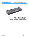
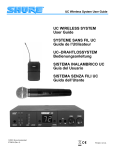
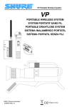
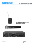
PRODUCT INFORMATION LX88-II Wireless System User Guide SHURE Incorporated Web Address: http://www.shure.com 222 Hartrey Avenue, Evanston, IL 60202–3696, U.S.A. Phone: 847-866–2200 Fax: 847-866-2279 In Europe, Phone: 49-7131-72140 Fax: 49-7131-721414 In Asia, Phone: 852-2893-4290 Fax: 852-2893-4055 Elsewhere, Phone: 847-866–2200 Fax: 847-866-2585 2000, Shure Incorporated 27A8582 (TG) Printed in U.S.A. TABLE OF CONTENTS ENGLISH SYSTEM CONTENTS . . . . . . . . . . . . . . . . . . . . . . . . . . . . . . . . . . . . . . . . . . . . . . . . . . . . . 1 LX88-II RECEIVER FEATURES & CONTROLS . . . . . . . . . . . . . . . . . . . . . . . . . . . . . . . 2 LX2 HANDHELD MICROPHONE-TRANSMITTER FEATURES & CONTROLS . . . . . 3 LX1 BODY-PACK TRANSMITTER FEATURES & CONTROLS . . . . . . . . . . . . . . . . . . . 4 SYSTEM INSTALLATION . . . . . . . . . . . . . . . . . . . . . . . . . . . . . . . . . . . . . . . . . . . . . . . . . 5 MOUNTING THE RECEIVER . . . . . . . . . . . . . . . . . . . . . . . . . . . . . . . . . . . . . . . . . . . . . . 5 CONNECTING THE POWER SUPPLY . . . . . . . . . . . . . . . . . . . . . . . . . . . . . . . . . . . . . . . 6 CONNECTING THE ANTENNAS . . . . . . . . . . . . . . . . . . . . . . . . . . . . . . . . . . . . . . . . . . . 6 CONNECTING THE RECEIVER . . . . . . . . . . . . . . . . . . . . . . . . . . . . . . . . . . . . . . . . . . . . 7 LX2 HAND-HELD MICROPHONE TRANSMITTER SETUP . . . . . . . . . . . . . . . . . . . . . 8 LX1 BODY-PACK TRANSMITTER SETUP . . . . . . . . . . . . . . . . . . . . . . . . . . . . . . . . . . . 10 CHECKING THE TRANSMITTER BATTERY . . . . . . . . . . . . . . . . . . . . . . . . . . . . . . . . . . 12 TRANSMITTER AUDIO GAIN ADJUSTMENT . . . . . . . . . . . . . . . . . . . . . . . . . . . . . . . . . 12 RECEIVER SQUELCH ADJUSTMENT . . . . . . . . . . . . . . . . . . . . . . . . . . . . . . . . . . . . . . 13 TIPS FOR GETTING THE BEST PERFORMANCE . . . . . . . . . . . . . . . . . . . . . . . . . . . . 14 TROUBLESHOOTING . . . . . . . . . . . . . . . . . . . . . . . . . . . . . . . . . . . . . . . . . . . . . . . . . . . . 14 SPECIFICATIONS . . . . . . . . . . . . . . . . . . . . . . . . . . . . . . . . . . . . . . . . . . . . . . . . . . . . . . . . 15 LICENSING INFORMATION . . . . . . . . . . . . . . . . . . . . . . . . . . . . . . . . . . . . . . . . . . . . . . . 17 WARRANTY INFORMATION . . . . . . . . . . . . . . . . . . . . . . . . . . . . . . . . . . . . . . . . . . . . . . . 17 CHINESE (FROM CAMERA-READY ART) CONGRATULATIONS! The LX88-II Wireless System is the finest in its class. This system will give you excellent performance for years to come. SYSTEM CONTENTS The LX88-II Wireless System contains the following components: • One LX88-II dual channel wireless receiver • Two transmitters available in one of three different combinations (see System Combinations below) • Two antennas • One PS20 (120 Vac) or PS20E (230 Vac) power adapter • One hardware kit • Two rackmount brackets System Combinations The LX88-II system includes one of the following three transmitter combinations: • Two handheld microphone transmitters (includes two swivel adapters and two anti-roll devices) or • Two body-pack transmitters or • One handheld microphone and one body-pack transmitter (includes one swivel adapter and one anti-roll device) 1 LX88-II Receiver Features & Controls (Figure 1) LX2 Handheld Microphone-Transmitter Features & Controls (Figure 2) FRONT 1 2 3 1 4 2 3 4 Á ÁÁÁ Á Á ÁÁ ÁÁÁ ÁÁ Á Á ÁÁÁ ÁÁ Á Á ÁÁ Á Á ÁÁ Á Á ÁÁ Á ÁÁ Á ÁÁ Á ÁÁ Á Á ÁÁ Á Á Á Á ÁÁ ÁÁ Á Á 5 BACK 6 7 8 9 7 6 LX88-II DUAL CHANNEL RECEIVER FEATURES & CONTROLS FIGURE 1 Front 1. Power Indicators. 2. RF Signal Indicators. Yellow indicates when RF (radio frequency) signals are received from the transmitter. 3. Audio Peak Indicators. This light flickers occasionally in normal operation; is ON 1 Á ÁÁ Á Á Á ÁÁ Á Á ÁÁ Á Á ÁÁ ÁÁ Á 2 BAT 3 4 MUTE 5 LX2 6 LX2 MICROPHONE–TRANSMITTER FEATURES & CONTROLS FIGURE 2 steadily when the audio input is overloaded. 4. Volume Controllers. Controls the audio output level. 5. POWER ON/OFF Switch. 1. Grille. Back 6. Antenna Connectors. 2. Power ON/OFF Switch. 7. Independent Audio Output Connectors. There is a separate balanced XLR connector and unbalanced 1/4–inch phone jack for each channel. 3. Power/Battery Fuel Gauge. Indicates the power level of the battery. 8. Mixed Channels Audio Output Connector. An unbalanced, 1/4–inch phone jack connector mixes both channels into a single output. This comes in handy when the mixer or amplifier has only one audio input. 4. Mic On/Mute Switch. “Mutes” the transmitter to prevent unwanted sounds 9. Power Input Connector. Connects to a PS20 (120 Vac) or PS20E (230 Vac) power adapter. from being picked up by the receiver without turning the transmitter off. 5. Audio Gain Control. Provides audio level adjustment to accommodate different sound sources. 6. Battery Cover. Access to the battery and the audio gain control. 2 3 LX1 Body-Pack Transmitter Features & Controls (Figure 3) 6 Á Á ÁÁÁÁÁÁÁÁÁ ÁÁÁÁ Á ÁÁ ÁÁ ÁÁ Á ÁÁÁ 3 2 ON MUTE BAT OFF PWR 1 5 4 ÁÁÁÁ ÁÁÁÁ ÁÁ Á ÁÁÁÁ ÁÁÁ ÁÁÁÁ ÁÁÁÁ ÁÁ Á ÁÁÁÁ ÁÁÁ Á ÁÁÁÁ ÁÁÁÁ ÁÁÁ ÁÁ Á ÁÁÁ Á ÁÁÁÁÁ ÁÁÁÁ ÁÁÁ ÁÁÁÁ ÁÁ Á Á ÁÁÁ ÁÁÁÁ Á Á ÁÁ Á ÁÁÁ ÁÁÁÁ ÁÁÁ Á ÁÁÁ 8 SYSTEM INSTALLATION MOUNTING THE RECEIVER The LX88-II Dual Channel Wireless Receiver can be mounted in two ways: as a stand-alone unit or as a rack-mount unit. As a Stand-Alone Unit (Figure 4) 7 LX1 BODY-PACK TRANSMITTER FEATURES & CONTROLS FIGURE 3 1. POWER ON/OFF Switch. 2. Power/Battery Fuel Gauge. Indicates the power level of the battery. 3. Input Jack. Tini “Q-G” input connector for microphones or instruments. 4. Mic On/Mute Switch. “Mutes” the transmitter to prevent unwanted sounds from being picked up by the receiver without turning the transmitter off. 5. Belt Clip. Secures Body-Pack to clothing or guitar strap. 6. Antenna. For best operation, the antenna must hang vertically, it should not be coiled or bundled. 7. Audio Gain Control. Provides audio level adjustment to accommodate different sound sources. 8. Battery Compartment. Access to the battery. INSTALLING RUBBER FEET FIGURE 4 1. Turn the unit upside-down. 2. Place the rubber feet supplied with the package in the four corners of the base. 3. Turn the unit rightside-up. It can now be mounted on any flat surface, such as a table, with the feet working as anchors to prevent slipping. As a Rack-Mount Unit 1. Remove the two screws from each side of the receiver. 2. Position the mounting brackets over the holes on the sides of the receiver and secure to the receiver with the screws from Step 1 (Figure 5). ÁÁ ÁÁ ÁÁÁ ÁÁÁ RACK–MOUNTED RECEIVER FIGURE 5 ÁÁÁÁ ÁÁ ÁÁÁÁ 3. Secure the assembly to a standard audio equipment rack with four screws (Figure 6). ÁÁÁÁ ÁÁÁÁ Á ÁÁÁ ÁÁ Á ÁÁÁÁ ÁÁÁ ÁÁÁÁ ÁÁÁÁ INSTALLING RECEIVER IN A RACK FIGURE 6 4 5 4. If the antennas are to be remote mounted, insert the supplied plastic plugs into the holes on the front of the brackets (Figure 7). ÁÁÁ ÁÁ Á ÁÁÁÁ ÁÁÁ ÁÁ ÁÁÁÁ ÁÁÁÁ ÁÁÁÁ INSTALLING THE HOLE PLUGS FIGURE 7 NOTE: If you install the receiver in a rack mount, we recommend you front mount or remote mount your antennas. CONNECTING THE RECEIVER There are two ways to connect the receiver to a mixer or a karaoke unit: Two Independent Channels (Figure 9) LX88-II BACK AUDIO MIXER or KARAOKE UNIT CONNECTING THE POWER SUPPLY AC ADAPTER (PS20E) 1. Connect the ac adapter to the POWER jack on the rear panel of the receiver. CONNECTING SEPARATE CHANNELS FIGURE 9 2. Plug the ac adapter into an appropriate power outlet. CONNECTING THE ANTENNAS There are several ways the antennas can be connected to the receiver. • When used as a stand-alone unit, attach the supplied quarter-wave antennas to the antenna connectors on the receiver back panel. For best performance, the receiver antennas should point straight up (Figure 8). Á ÁÁ Á Connect the receiver outputs for channels 1 and 2 to the mixer or karaoke unit inputs using balanced, 2–conductor, shielded cables with 3-pin XLR connectors, or unbalanced, single–conductor, shielded cables with 1/4-inch phone plugs. Two Channels Mixed Into One (Figure 10) LX88-II BACK AUDIO MIXER or KARAOKE UNIT INSTALLING THE ANTENNAS FIGURE 8 • If you wish to front mount the antennas, ask your Shure dealer for information on the WA503 Front Mount Conversion Kit. • If you wish to remote mount the antennas, ask your Shure dealer for information on the WA380 1/2-Wave telescoping antennas or WA490 1/2-Wave cable antennas and a WA421 cable extension kit. 6 AC ADAPTER (PS20E) CONNECTING MIXED CHANNELS FIGURE 10 Connect the Mixed Channels output to the mixer or karaoke unit input using an unbalanced, single-conductor, shielded cable with a 1/4-inch phone plug. 7 LX2 HAND-HELD MICROPHONE TRANSMITTER SETUP Operating the LX2 Hand-Held Microphone Transmitters (Figure 13) Battery Installation (Figure 11) 1. Press the POWER switch on the LX88-II receiver ON. 1. With the transmitter PWR ON/OFF switch in the OFF position, hold the upper part of the transmitter and unscrew the battery cover. Á ÁÁ Á ÁÁÁ Á ÁÁ Á ÁÁ ÁÁÁ ÁÁ Á Á Á Á Á ÁÁ Á Á Á Á Á ÁÁ Á Á Á ÁÁ ÁÁ Á Á Á Á Á Á Á Á ÁÁ Á Á LX2 MICROPHONE-TRANSMITTER BATTERY INSTALLATION 2. Slide the transmitter POWER ON/OFF switch to the PWR position. Check the battery level. See Checking the Transmitter Battery. 3. Check the RF indicator on the LX88-II receiver to see if the radio signal is being received. 4. Slide the transmitter ON/MUTE switch to the ON position and begin speaking or singing. NOTE: If the red PEAK light on the receiver does not flicker during the loudest sounds, the transmitter gain may need to be increased. See the Transmitter Audio Gain Adjustment section. 5. During the performance or presentation, slide the ON/MUTE switch to the MUTE position when the microphone is not being used. FIGURE 11 2. Install a fresh 9V alkaline battery (DURACELL MN1604 recommended). Make sure the battery terminals match the terminals in the transmitter. 6. When the performance or presentation is over, slide the transmitter POWER ON/OFF switch to the OFF position to conserve battery power. 3. Replace the battery cover. Installing the Anti–Roll Device The rubber anti-roll device prevents hand-held microphones from rolling off onto the ground when they are set down on a flat surface, such as a table or speaker cabinet. The anti-roll device proves an important safeguard in stage situations where the LX2 may be used by inexperienced microphone handlers. To install the anti-roll device, simply slip it over the microphone handle and slide it up so that it is positioned just below the label under the microphone grille, as shown in Figure 12. ÁÁÁÁÁÁÁ Á ÁÁÁÁ Á Á ÁÁÁÁÁ Á ÁÁÁÁ Á ÁÁÁÁÁÁÁÁÁÁ ÁÁ ÁÁÁ ÁÁÁÁÁÁÁÁ Á Á Á ÁÁÁÁ Á Á ÁÁÁ ÁÁÁÁÁ ÁÁÁ Á ÁÁ Á LX2 TRANSMITTERS ÁÁ Á ÁÁ ÁÁ ÁÁ Á ÁÁ Á Á Á ÁÁ Á Á ÁÁ Á LX88-II RECEIVER LX2 HAND–HELD MICROPHONE SYSTEM OPERATION FIGURE 13 ANTI-ROLL DEVICE INSTALLATION FIGURE 12 8 9 BODY-PACK TRANSMITTER SETUP LX1 Body-Pack Transmitter Battery Installation (Figure 14) NOTE: The LX1 body-pack system is designed for use with other equipment which is not included, such as lavalier microphones, guitars, headset microphones, etc. See your Shure dealer for details on ordering the proper equipment for your needs. Á ÁÁ Á ÁÁÁ Á ÁÁ Á Á Á ÁÁÁ Á Á Á Á Á Á Á Á Á ÁÁ Á -+ 1. Clip the LX1 body pack transmitter to your belt or guitar strap. Á ÁÁÁ Á Á Á Á Á Á Á Á ÁÁÁ Á 2. Connect the lavalier microphone, headset or instrument adapter cable to the body–pack transmitter (Figure 16). 3. Press the POWER button on the LX88-II receiver ON. 4. Turn the transmitter POWER switch ON. Check Power/Battery fuel gauge. LX1 BODY–PACK TRANSMITTER BATTERY INSTALLATION FIGURE 14 1. With the transmitter POWER ON/OFF switch in the OFF position, press down on the OPEN side of the battery compartment cover, slide it back and flip it open. 2. Insert a new 9V alkaline battery in the compartment (DURACELL MN1604 recommended). Observe proper battery polarity (“+/–”). 3. Close Battery compartment cover. Operating LX1 Body-Pack Transmitters (Figure 15) WH10 HEADSET WM98 MIC & A98KCS HORN MOUNT Á Á ÁÁÁ WA302 INSTRUMENT ADAPTER CABLE Á ÁÁÁ ÁÁÁÁ ÁÁ ÁÁÁÁ ÁÁÁ ÁÁÁÁ ÁÁÁÁ ÁÁ Á Á ÁÁÁ ÁÁÁÁ ÁÁ Á ÁÁÁÁÁ ÁÁ Á ÁÁ Á Á ÁÁÁÁ Á Á ÁÁÁÁÁ ÁÁ Á ÁÁ ÁÁÁÁ ÁÁÁ Á Á ÁÁÁÁ ÁÁÁÁÁ ÁÁÁÁ Á ÁÁÁÁ Á Á ÁÁÁÁ ÁÁÁ MICROPHONE CABLE OR WA302 INSTRUMENT ADAPTER CABLE LX1 BODY-PACK TRANSMITTER CABLE CONNECTION FIGURE 16 LAVALIER MIC 6. Slide the transmitter ON/MUTE switch to the ON position and begin speaking or playing your instrument. Á LX88-II RECEIVER NOTE: If the red PEAK light on the receiver does not flicker during the loudest sounds, the transmitter gain may need to be increased. See the Transmitter Audio Gain Adjustment section. 7. During the performance or presentation, slide the ON/MUTE switch to the MUTE position when the system is not being used. LX1 BODY–PACK SYSTEM SETUP AND OPERATION FIGURE 15 10 5. Check the RF Signal Indicator on the LX88-II receiver to see if the RF signal is being received. 8. When the performance or presentation is over, slide the transmitter POWER ON/OFF switch to the OFF position to conserve battery power. 11 CHECKING THE TRANSMITTER BATTERY Battery Life Indicators or never on, the transmit audio level may require adjustment. Use the gain controls as follows to adjust the equipment for the best sound quality. Remaining Transmitter Operating Time* Green 6 to 20 hours Green and Amber 4 to 6 hours Amber 2 to 4 hours Red 1 hour or less To adjust the audio gain, locate the transmitter audio gain control and use the supplied screwdriver to adjust the control. • If the PEAK light is always on, decrease the audio gain by turning the gain control counter–clockwise (while the vocalist is singing or the musical instrument is being played) until the PEAK light on the receiver flickers only occasionally. * Estimated operating time assumes the use of a fresh 9 V alkaline battery (Duracell MN1604). NOTE: The above battery life indicator readings apply for 9V alkaline batteries ONLY. Transmitter operating time for rechargeable 8.4V nicad batteries vary with type, brand and number of times the battery has been used. Actual operating times for rechareable batteries are not predictable. • If the PEAK light is never on, increase the audio gain by turning the gain control clockwise (while the vocalist is singing or the musical instrument is being played) until the PEAK light on the receiver flickers only occasionally. RECEIVER SQUELCH ADJUSTMENT (FIGURE 18) WARNING: Batteries inside transmitters in long-term storage may corrode and leak acid, causing damage to the transmitter. For long-term storage, remove batteries from the transmitter. SQUELCH DECREASE INCREASE TRANSMITTER AUDIO GAIN ADJUSTMENT (FIGURE 17) LX1 DECREASE GAIN LX2 Á ÁÁÁ ÁÁÁ Á Á ÁÁ Á ÁÁ Á Á Á Á ÁÁÁ ÁÁÁ ÁÁ ÁÁÁ Á Á Á Á Á Á Á Á Á ÁÁÁ ÁÁ DECREASE GAIN INCREASE GAIN INCREASE GAIN TRANSMITTER AUDIO GAIN ADJUSTMENT FIGURE 17 The transmitter audio gain control has been factory preset to provide satisfactory output. However, if the PEAK light on the LX88-II receiver is constantly on 12 ÁÁÁ ÁÁÁÁÁÁÁÁÁÁ ÁÁÁÁ Á ÁÁÁ ÁÁÁÁ Á Á ÁÁ Á Á Á Á Á ÁÁ Á ÁÁÁ ÁÁÁÁ ÁÁ ÁÁ Á ÁÁÁ ÁÁ ÁÁÁÁÁ LX88-II RECEIVER SQUELCH CONTROL ADJUSTMENT FIGURE 18 The receiver squelch control is factory preset at the 12 o’clock position for optimum performance. No further adjustment is normally required. However, it is possible to adjust the squelch control to emphasize either signal quality or system range. • To raise the squelch threshold, rotate the control clockwise. This causes the receiver to demand a higher quality signal (less noise before muting), but it reduces the operating range. • To lower the squelch threshold, rotate the control counterclockwise. This allows a lower quality signal through (more noise before muting), but it extends the operating range. 13 TIPS FOR GETTING THE BEST PERFORMANCE • Maintain a line-of-sight between the transmitter and receiver antennas. • Keep the receiver and antennas away from large metal objects. • Avoid placing the receiver near computers or other RF generating equipment. • Point the antennas straight up. • Avoid placing the receiver in the bottom of an equipment rack unless the antennas are remotely located. • Use the proper receiver antennas. 1/4-wave antennas can be used if mounted directly on the receiver or front mounted on the rack ears using the WA503 Front Mount Conversion Kit; 1/2-wave or other ground-plane-dependent antennas must be used if antennas are remotely located. TROUBLESHOOTING Some common problems and their solutions are identified in the table below. If you are unable to solve a problem, contact your dealer. Problem No sound; RF light(s) not glowing. Solution • Make sure the transmitter and receiver POWER switches are ON. • Check battery. • Check receiver squelch setting. • Check receiver antenna connection(s). • Make sure antennas are in line of sight of transmitter. No sound; RF and Audio Level • Turn up receiver audio VOLUME control. meter lights glowing. • Check for proper connection between receiver and karaoke unit. • Talk into microphone and observe receiver audio level lights. If they glow, the problem is elsewhere in the sound system. Received signal is noisy or con- • Check battery. tains extraneous sounds with • Remove local sources of RF interference. transmitter on. • If using a guitar or other instrument, check connections. • Two transmitters may be operating on the same frequency. Locate and turn one off. • Signal may be too weak. Reposition antennas. If possible, move them closer to transmitter. Noise from receiver with trans- • Adjust receiver squelch control. mitter off. • Remove local sources of RF interference. • Reposition receiver or antennas. Momentary loss of sound as • Reposition receiver and perform another transmitter is moved around per“walkthrough” test and observe the RF forming area. indicators. If audio dropouts persist, mark these “dead spots” in performing area and avoid them during performance. 14 SPECIFICATIONS RF Carrier Frequency Range 169.445 to 221.350 MHz Working Range 100 m (approximately 300 ft) under typical conditions. Audio Frequency Response 50 to 15,000 Hz, ±2 dB. Audio Output Level (±15 kHz deviation, 1 kHz tone) XLR connector (into 600 Ω load): –20 dBV (mic) 1/ inch connector (into 3 kΩ load) –8.8 dBV (Hi Z) 4– : 1/ inch connector (into 3 kΩ load) –18dBV (mix) 4 : Gain Adjustment Range LX1: 40 dB LX2: 25 dB Impedances LX1 (input): 1 MΩ LX88-II (output): 600 Ω (XLR); 5 kΩ (1/4-inch phone jack) RF Power Output LX1, LX2: 50 mW maximum (complies with FCC and IC regulations) RF Sensitivity –101 dBm, typical Audio Polarity Positive pressure on microphone diaphragm (or positive voltage applied to tip of WA302 phone plug) produces positive voltage on pin 2 with respect to pin 3 of low impedance output and tip of high impedance 1/4-inch output. System Distortion (ref. ±15 kHz deviation, 1 kHz modulation) 0.7% Power Requirements LX1, LX2: 9V alkaline battery (Duracell MN1604 recommended). 8.4V Nicad (rechargeable) are optional but not recommended. LX88-II: 12 Vdc (PS20, 120Vac; PS20E, 230 Vac Power Supply) Current Drain LX1: 31 mA average (40 mA max), LX2: 30 mA average (35 mA max) LX88-II: 160 mA average (195 mA max) Operating Temperature Range -20° to 50° C (-4° to 122° F). NOTE: Battery characteristics may limit this range. Overall Dimensions LX1: 82.6 mm H x 63.5 mm W x 26.2 mm D (31/4 x 21/2 x 11/32 in.) LX2/58: 241 mm L x 50.8 mm Dia. (91/2 x 2 in.) LX88-II: 44 mm H x 349 mm W x 194mm D (1 3/4 x 13 3/4 x 7 5/8 in) Net Weight LX1: 79.5 g (2.8 oz) without battery LX2/58: 294.8 g (10.4 oz) without battery LX88-II: 1.7 Kg (3.7 lbs) Certification LX1, LX2: Type-accepted under FCC Parts 90 and 74; IC certified under TRC-78 15 FURNISHED ACCESSORIES LICENSING INFORMATION Receiver Rack Mount Brackets . . . . . . . . . . . . . . . . . . . . . . . . . . . . . . . 53A8425 Hardware Kit . . . . . . . . . . . . . . . . . . . . . . . . . . . . . . . . . . . . . . . . . . . . . . 90TZ1371 Swivel Adapter (hand-held only) . . . . . . . . . . . . . . . . . . . . . . . . . . . . . . WA370A Anti-Roll Device (hand-held only) . . . . . . . . . . . . . . . . . . . . . . . . . . . . . 66A4083 Changes or modifications not expressly approved by Shure Brothers Inc. could void your authority to operate the equipment. Licensing of Shure wireless microphone equipment is the user’s responsibility, and licensability depends on the user’s classification and application, and on the selected frequency. Shure strongly urges the user to contact the appropriate telecommunications authority concerning proper licensing, and before choosing and ordering frequencies other than standard frequencies. OPTIONAL ACCESSORIES Microphone Adapter Cable (LX1) . . . . . . . . . . . . . . . . . . . . . . . . . . . . . . WA310 Switchcraft TA4F Female 4-Pin Connector (LX1) . . . . . . . . . . . . . . . . . WA330 In-Line Audio Switch (LX1) . . . . . . . . . . . . . . . . . . . . . . . . . . . . . . . . . . . WA360 1/ -Wave Telescoping Antenna (169–185 MHz) . . . . . . . . . . . . . . . . WA380A* 2 1/ -Wave Telescoping Antenna (185–200 MHz) . . . . . . . . . . . . . . . . WA380B* 2 1/ -Wave Telescoping Antenna (200–230 MHz) . . . . . . . . . . . . . . . . WA380C* 2 Antenna/Power Distribution System, 120 Vac . . . . . . . . . . . . . . . . . . . WA404 Antenna/Power Distribution System, 230 Vac . . . . . . . . . . . . . . . . . . WA404E 1.8 Meter (6 ft.) Receiver-Mixer Cable (1/4” phone to XLR) . . . . . . . . WA410 6.1 Meter (20 ft.) Antenna Extension Cable . . . . . . . . . . . . . . . . . . . . . WA421 Antenna Rack Mount Kit . . . . . . . . . . . . . . . . . . . . . . . . . . . . . . . . . . . . . . WA440 Passive Antenna Splitter . . . . . . . . . . . . . . . . . . . . . . . . . . . . . . . . . . . . . WA470 1/ -Wave Cable Antenna (169–185 MHz) . . . . . . . . . . . . . . . . . . . . . . WA490A 2 1/ -Wave Cable Antenna (185–200 MHz) . . . . . . . . . . . . . . . . . . . . . . WA490B 2 1/ -Wave Cable Antenna (200–216 MHz) . . . . . . . . . . . . . . . . . . . . . . WA490C 2 Single Receiver Front-Mount Antenna Conversion Kit . . . . . . . . . . . . WA503 *Includes wall-mounting bracket for remote antenna placement REPLACEMENT PARTS SM58 Cartridge with Grille (LX2/58) . . . . . . . . . . . . . . . . . . . . . . . . . . . . . . R158 AC Adapter . . . . . . . . . . . . . . . . . . . . . . . . . PS20 (120 Vac)/PS20E (230 Vac) Matte Silver Grille (LX2/58) . . . . . . . . . . . . . . . . . . . . . . . . . . . . . . . . . . RK143G Belt Clip (LX1 ) . . . . . . . . . . . . . . . . . . . . . . . . . . . . . . . . . . . . . . . . . . . . 53A8247A 1/ -Wave Antenna . . . . . . . . . . . . . . . . . . . . . . . . . . . . . . . . . . . . . . . . . . 90A8380 4 16 WARRANTY INFORMATION Shure Incorporated (“Shure”) hereby warrants that these products will be free from defects in material and workmanship for a period of one year from the date of purchase. At its option, Shure will repair or replace the defective product and promptly return it to you, or refund the purchase price. Retain proof of purchase to validate the purchase date and return it with any warranty claim. If you believe this product is defective within the warranty period, carefully repack the unit, insure it, and return it postpaid to: Shure Incorporated Attention: Service Department 222 Hartrey Avenue Evanston, IL 60202-3696 U.S.A. Telephone: (847) 866-5730 For service outside the United States, return the product to any authorized Shure Distribution Center. All claims of defects or shortage should be directed to the above address. Please furnish model number, operating frequency, and date, place and proof of purchase (such as a copy of your sales receipt) to establish warranty. Your letter should include all pertinent details including applicable model or part numbers and a brief description of the problem. Do not mail any units or parts to Shure unless requested to do so by Shure’s Service Department. Any returned items must have prior authorization. Unauthorized returns are delayed in handling; these delays can be avoided by contacting Shure in advance and furnishing the necessary information. Shure reserves the right to make design changes and product improvements on any previously manufactured products. Shure also reserves the right to ship new and/or improved products which are similar to the form, fit and function of the originally ordered products. 17