1
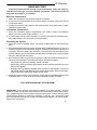
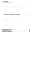
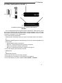
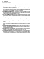
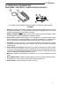
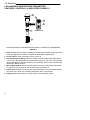
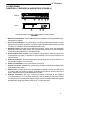
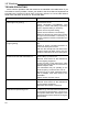
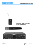
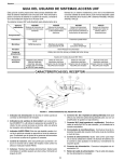
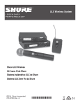
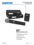
Shure Brothers Incorporated 222 Hartrey Avenue Evanston IL 60202-3696 U.S.A. www.shure.com LX Wireless System User Guide E1999, Shure Brothers Incorporated 27B8654 (SC) LX Wireless THANK YOU... ...for selecting the Shure LX Wireless Microphone System This guide is intended to help you get the most out of your LX wireless microphone system. If you have questions about your system that are not answered in this guide, please contact Shure Customer Service at 847-866-2553, Monday through Friday, 8:00 am - 4:30 pm CST. In Europe, please call Shure GmbH in Germany at 49-7131-72140. Other international users please call Shure Brothers Inc. in the U.S.A. at 847-866-2200. 2 LX Wireless READ ME FIRST! To get your system up and running in just a few minutes, follow the simple instructions on this page. For more detailed information, refer to the sections of this guide that apply to your system. Receiver Connections 1. Attach the antennas to the receiver antenna connectors. 2. Connect the ac power adapter to the receiver power connector; then plug it into an ac electrical outlet. 3. Connect the receiver audio output to the sound system, using either a low- or highimpedance audio cable. Transmitter Connections 1. Open the transmitter battery compartment and insert a fresh 9-volt alkaline battery. Observe proper battery polarity ( “+/–”). 2. If you are using a body-pack transmitter, connect the microphone or WA302 instrument cable to the 4-pin connector on the transmitter. Operating the System 1. Press the receiver POWER switch. The green POWER light on the receiver will glow. 2. Set the transmitter PWR/OFF switch to PWR and the ON/MUTE switch to ON. One of the three lights on the transmitter will glow, indicating both that the transmitter is on and the amount of battery life remaining. Two sets of five RF level lights on the receiver will also glow to indicate the strength of the received signal. The more lights that glow, the stronger the signal. 3. Have someone talk or sing into the microphone, or play the musical instrument connected to the transmitter. The audio level will be indicated as follows: - Green lights (3) glowing indicates normal operation. - Amber light glowing indicates approaching audio overload (should only occur during loud signals). - Red light glowing steadily indicates audio overload. If this happens, reduce the transmitter gain until it flickers only during the loudest signals. Refer to the Transmitter Audio Gain Adjustment section of this guide. 4. Adjust the receiver LEVEL control until the output level is compatible with the mixer or amplifier input. In most cases, this control should be set fully clockwise. YOU ARE NOW READY TO PERFORM! IMPORTANT: Every wireless microphone installation is a unique situation, and can present a variety of problems. Never attempt a live performance without first conducting a “walkthrough” test of the system in the performing area. If major changes (additional wireless systems or intercoms, relocation of scenery, etc.) have been made since the last walk–through test, check the wireless system again—as close to performance time as possible. 3 LX Wireless TABLE OF CONTENTS SYSTEM COMPONENTS . . . . . . . . . . . . . . . . . . . . . . . . . . . . . . . . . . . . . . . . . . . . . . . . 5 SYSTEM FEATURES . . . . . . . . . . . . . . . . . . . . . . . . . . . . . . . . . . . . . . . . . . . . . . . . . . . . 6 LX1 BODY-PACK TRANSMITTER FEATURES, CONTROLS & INDICATORS . . . 7 LX2 HAND-HELD TRANSMITTER FEATURES, CONTROLS & INDICATORS . . . 8 LX3 RECEIVER FEATURES, CONTROLS & INDICATORS . . . . . . . . . . . . . . . . . . . 9 LX4 DIVERSITY RECEIVER FEATURES, CONTROLS & INDICATORS . . . . . . . 10 RECEIVER MOUNTING . . . . . . . . . . . . . . . . . . . . . . . . . . . . . . . . . . . . . . . . . . . . . . . . 11 Single Rack Mounted Receiver . . . . . . . . . . . . . . . . . . . . . . . . . . . . . . . . . . . . . . 11 Double Rack Mounted Receivers . . . . . . . . . . . . . . . . . . . . . . . . . . . . . . . . . . . . 11 RECEIVER CONNECTIONS . . . . . . . . . . . . . . . . . . . . . . . . . . . . . . . . . . . . . . . . . . . . . 12 TRANSMITTER SETUP . . . . . . . . . . . . . . . . . . . . . . . . . . . . . . . . . . . . . . . . . . . . . . . . . 13 LX1 Body–Pack Transmitter Battery Installation . . . . . . . . . . . . . . . . . . . . . . . . . 13 LX2 Hand–Held Microphone–Transmitter Battery Installation . . . . . . . . . . . . . 13 Checking the Transmitter Battery . . . . . . . . . . . . . . . . . . . . . . . . . . . . . . . . . . . . . 14 Connecting a Lavalier Microphone or Instrument Cable to the LX1 . . . . . . . . 14 Attaching the LX1 to a Belt or Guitar Strap . . . . . . . . . . . . . . . . . . . . . . . . . . . . . 15 Installing the WA555 Grip/Switch Cover Accessory on the LX2 . . . . . . . . . . . . 15 OPERATING LX1 BODY–PACK SYSTEMS . . . . . . . . . . . . . . . . . . . . . . . . . . . . . . . . 16 OPERATING THE LX2 HAND–HELD SYSTEM . . . . . . . . . . . . . . . . . . . . . . . . . . . . . 17 GAIN AND SQUELCH ADJUSTMENT . . . . . . . . . . . . . . . . . . . . . . . . . . . . . . . . . . . . 18 Adjusting the Transmitter Audio Gain Level . . . . . . . . . . . . . . . . . . . . . . . . . . . . 18 Adjusting the Receiver Squelch Control . . . . . . . . . . . . . . . . . . . . . . . . . . . . . . . . 19 TIPS FOR ACHIEVING OPTIMUM PERFORMANCE . . . . . . . . . . . . . . . . . . . . . . . 19 TROUBLESHOOTING . . . . . . . . . . . . . . . . . . . . . . . . . . . . . . . . . . . . . . . . . . . . . . . . . . 20 SPECIFICATIONS . . . . . . . . . . . . . . . . . . . . . . . . . . . . . . . . . . . . . . . . . . . . . . . . . . . . . . 21 FURNISHED ACCESSORIES . . . . . . . . . . . . . . . . . . . . . . . . . . . . . . . . . . . . . . . . . . . 22 OPTIONAL ACCESSORIES . . . . . . . . . . . . . . . . . . . . . . . . . . . . . . . . . . . . . . . . . . . . . 22 REPLACEMENT PARTS . . . . . . . . . . . . . . . . . . . . . . . . . . . . . . . . . . . . . . . . . . . . . . . . 23 LICENSING INFORMATION . . . . . . . . . . . . . . . . . . . . . . . . . . . . . . . . . . . . . . . . . . . . . 23 4 LX Wireless SYSTEM COMPONENTS (FIGURE 1) WIRELESS RECEIVER SQUELCH LEVEL POWER AUDIO RF LX1 LX3 LX2 MARCAD DIVERSITY SQUELCH LEVEL RF A RF B POWER AUDIO LX4 LX WIRELESS MICROPHONE SYSTEM COMPONENTS FIGURE 1 Your LX Wireless Microphone System features a MARCAD fixed frequency diversity receiver operating in the VHF band between 169 and 240 MHz. Up to 12 LX wireless systems can be operated simultaneously in a single installation. Each LX system contains a combination of the following items: • One of the following transmitters: LX1 Body-Pack Transmitter, with your choice of instrument cable or microphone, • • • • or LX2 Hand-Held Microphone-Transmitter with your choice of interchangeable microphone heads: - SM58 cardioid dynamic microphone - BETA 58 supercardioid premium dynamic microphone - SM87 supercardioid condenser microphone - BETA 87 supercardioid premium condenser microphone One of the following half-rack size receivers: LX3 Receiver or LX4 Diversity Receiver Both single and dual rack-mounting hardware One antenna (LX3 systems) or two antennas (LX4 systems) One of the following ac power adapters: PS40, PS40E, or PS40UK. 5 LX Wireless SYSTEM FEATURES Shure LX Wireless Systems offer a number of exceptional features, including: • Exclusive Shure MARCAD Circuitry (LX4). MARCAD (MAximum Ratio Combining Audio Diversity) circuitry constantly monitors signals from both receiver sections and combines them to create a single output signal. The result is improved reception and exceptional freedom from dropouts. • Half-Rack Receiver Size. The LX3 and LX4 receivers interface with the HR (halfrack) format, and are supplied with both single and dual rack-mount hardware. An optional WA503 accessory kit lets you front-mount antennas. • Power/Battery Fuel Gauge. The LX1 and LX2 transmitters include a three-light gauge that indicates both “power on” and the amount of battery life remaining. (Refer to the Checking the Transmitter Battery section.) • Dual RF Level Meters (LX4). Instead of a conventional single RF meter, the LX4 receiver has two meters, one for each antenna. The dual meters indicate received signal strength at each antenna, and make it easier to identify and troubleshoot RF “dead spots.” • Audio Metering. A five-light audio meter helps to optimize transmitter gain setting and lets you monitor audio level during operation. • True Guitar Sound. Guitar players demanding the highest degree of sound quality and reliability will appreciate the low noise and uncolored sound of the LX Wireless System. • Noise Squelch. This circuit analyzes signal quality instead of signal strength. This virtually eliminates the possibility of annoying noise bursts coming through your receiver. • Body-Pack Transmitter Belt Clip. The belt clip has a wider contact surface for a better grip, and firmly holds thinner, more slippery materials. It can be removed or inverted for special positioning. • Grip/Switch Cover Accessory. The unbreakable WA555 grip/switch cover accessory, supplied with all LX2 hand-held microphone-transmitters, prevents accidental movement of the power and mute switches and provides a “grip” feel. • Compact Power Adapter. The supplied ac power adapter incorporates small, inline transformers that save space on ac power strips. It also has mounting tabs so it can be secured to any surface, as well as locking dc power connectors to prevent accidental disconnection from the receiver. 6 LX Wireless LX1 BODY-PACK TRANSMITTER FEATURES, CONTROLS, & INDICATORS (FIGURE 2) 1 2 4 5 ON MUTE BAT OFF PWR 8 3 6 7 LX1 BODY-PACK TRANSMITTER FEATURES, CONTROLS & INDICATORS FIGURE 2 1. Antenna. A flexible wire antenna is permanently attached to the bottom of the LX1 body-pack transmitter. For best operation, the antenna must hang in the vertical position, and should not be coiled or bundled. 2. Battery Compartment. Hinged cover on bottom surface exposes the battery. Refer to the Body-Pack Transmitter Battery Installation section. 3. Audio Gain Control. Allows audio level adjustment to accommodate various sound sources (e.g., singing, speaking, or playing an instrument). A small screwdriver is supplied to make adjustments (see the Setting Audio Level section). 4. Input Jack. This is a Tini Q-G connector that provides connection with a variety of lavalier and headset microphone cables, and the Shure WA302 instrument adapter cable. 5. Power/Battery Fuel Gauge. When the Power switch is turned to the PWR position, one or two of the three lights on the transmitter will glow, indicating power to the unit. The color of the glowing light(s) indicates the amount of battery life remaining. Refer to the Checking the Transmitter Battery section. 6. Belt Clip. Allows the transmitter to be easily worn on a belt, waistband or guitar strap. 7. Mic On/Mute Switch. “Mutes” the transmitter to prevent unwanted sounds from being picked up by the receiver without turning the transmitter off. 8. Power Switch. Turns transmitter power on and off. 7 LX Wireless LX2 HANDHELD MICROPHONE-TRANSMITTER FEATURES, CONTROLS, & INDICATORS (FIGURE 3) 1 2 3 BAT 4 MUTE 5 LX2/BETA 58 6 LX2 MICROPHONE–TRANSMITTER FEATURES, CONTROLS, & INDICATORS FIGURE 3 1. Grille. Protects the microphone cartridge and helps reduce breath sounds and wind noise. The grilles for the various microphone heads differ in appearance. 2. Power Switch. Turns transmitter power on and off. 3. Power/Battery Fuel Gauge. When the Power switch is turned to the PWR position, one or two of the three lights on the transmitter will glow. The color of the glowing light(s) indicates the amount of battery life remaining. Refer to the Checking the Transmitter Battery section. 4. Mic On/Mute Switch. “Mutes” the transmitter to prevent unwanted sounds from being picked up by the receiver without turning the transmitter off. 5. Audio Gain Control. Provides audio level adjustment to accommodate different sound sources. Refer to the Setting Transmitter Audio Level section. 6. Battery Cover. Removable cup hides battery and audio gain control. 8 LX Wireless LX3 RECEIVER CONTROLS, FEATURES & INDICATORS (FIGURE 4) WIRELESS RECEIVER FRONT SQUELCH LEVEL POWER AUDIO RF 1 REAR 2 4 3 OUTPUT HI Z 5 POWER 6 ANT 12.5 – 18.9 VDC 7 8 9 LX3 RECEIVER CONTROLS, FEATURES, & INDICATORS FIGURE 4 1. RF Presence Indicators. Glows amber when the antenna is receiving usable RF (radio frequency) signals. 2. Audio Level Indicators. Five lights glow to indicate audio signal strength. Green lights indicate normal operation. An amber light indicates approaching overload condition. A red light indicates excessive audio levels. 3. Squelch Control. Sets the point at which the receiver “mutes” when the transmitter signal becomes noisy, weak or fails. This control is factory-set at the 12 o’clock position to provide optimal operation in most applications. 4. Audio Output Level Control. Lets you adjust output level to match the input level requirements of a mixer or amplifier. In most situations, this control should be set fully clockwise. 5. Power On Indicator. This green light glows to indicate that the Power switch is on and power is applied to the receiver. 6. Power On/Off Button. Turns the receiver on and off. 7. Output Connector. Quarter-inch phone jack provides unbalanced auxiliary level (high-impedance) output. 8. Power Jack: Accepts power from the supplied ac adapter, or from any filtered 15 to 18 Vdc (400 mA minimum) supply. It will also accept the dc power cord from a Shure WA405 Antenna Power/Distribution System. 9. Antenna Connector. UHF-type connector provides connection to the supplied 1/ -wave antenna or to coax cable used with a remote antenna. They also provide 4 connection to the optional Shure WA421 remote antenna cable kit used with optional WA380 telescoping and WA490 cable-type 1/2-wave antennas. 9 LX Wireless LX4 DIVERSITY RECEIVER CONTROLS, FEATURES & INDICATORS (FIGURE 5) MARCAD DIVERSITY SQUELCH LEVEL FRONT RF A 1 2 REAR 4 3 HI Z ANT OUTPUTS BAL 5 POWER B 6 7 ANT A MIC 8 POWER AUDIO RF B 9 10 LINE 9 12.5 – 18.9 VDC 11 8 LX4 DIVERSITY RECEIVER CONTROLS, FEATURES, & INDICATORS FIGURE 5 1. Diversity Signal Indicators for A and B Antennas. These lights glow amber when A, B, or both antennas are receiving usable RF (radio frequency) signals. 2. RF Level Indicators. Five lights per antenna glow to indicate RF signal strength. The more lights that glow, the stronger the received signal. If none of these lights glows, no signal is being received. 3. Audio Level Indicators. Five lights glow to indicate audio signal strength. Green lights indicate normal operation. An amber light indicates approaching overload condition. A red light indicates excessive audio levels. 4. Squelch Control. Sets the point at which the receiver “mutes” when the transmitter signal becomes noisy, weak or fails. This control is factory-set at the 12 o’clock position to provide optimal operation in most applications. 5. Audio Output Level Control. Lets you adjust output level to match the input level requirements of a mixer or amplifier. In most situations, this control should be set fully clockwise. 6. Power On Indicator. This green light glows to indicate that the Power switch is on and power is applied to the receiver. 7. Power On/Off Button. Turns the receiver on and off. 8. Antenna Connectors. UHF-type connectors provide connection to the supplied 1/ -wave antennas or to coax cable used with remote antennas. They also provide 4 connection to the optional Shure WA421 remote antenna cable kit used with optional WA380 telescoping and WA490 cable–type 1/2-wave antennas. 9. Output Connectors. XLR connector provides balanced low-impedance mic level or line-level output. Quarter-inch phone jack provides unbalanced auxiliary level (high-impedance) output. 10.Mic/Line Slide Switch: Controls output of balanced XLR connector. It can be set for microphone (-20 dBV maximum) or line-level (+0 dBV maximum). 11. Power Jack: Accepts power from the supplied ac adapter, or from any filtered 15 to 18 Vdc (400 mA minimum) supply. It will also accept the dc power cord from a Shure WA405 Antenna Power/Distribution System. 10 LX Wireless RECEIVER MOUNTING Single Rack–Mounted Receiver (Figure 6) If the receiver is to be located on a table or other horizontal surface, attach the four adhesive bumpers to the bottom corners of the receiver. If the receiver is to be mounted in an audio equipment rack, identify the rack-mount kits supplied with your system and follow the appropriate assembly directions below. 1. Remove two screws from each side of the receiver. 2. Position the large mounting brackets over the holes on the sides of the receiver and secure them to the receiver with the screws removed in Step 1. 3. If you are not going to front mount the antennas with a Shure WA503 Front Mount Conversion Kit, insert the plastic plugs into the holes in the brackets. 4. Secure the assembly to a standard audio equipment rack with four screws. SINGLE RACK–MOUNTED RECEIVER FIGURE 6 Double Rack–Mounted Receivers (Figure 7) 1. Remove the two screws on the outer side of each receiver. 2. Position the small mounting brackets over the holes on the outer side of each receiver, and secure them with the screws removed in Step 1. 3. Remove the screws on the inner side of each receiver. 4. Position two link bars over the holes and secure them with the screws removed in Step 3. For the receiver on the left, the link bar should be positioned so that its threaded hole is toward the front of the receiver. For the receiver on the right, the link bar should be positioned so that its threaded hole is toward the rear of the receiver. 5. Place the two receivers next to each other so that the threaded holes in the link bars line up, one on top of the other. 6. Fasten the receivers together by inserting a small screw from the top into the threaded hole at the front of the link bar. Then insert the other screw from the bottom into the threaded hole at the rear of the link bar. 7. Secure the assembly to a standard audio equipment rack, using four screws. LINK BARS DOUBLE RACK–MOUNTED RECEIVERS FIGURE 7 11 LX Wireless RECEIVER CONNECTIONS (FIGURE 8) 1. Attach the supplied quarter-wave antenna(s) to the antenna connector(s) on the receiver back panel. For best performance, the LX4 receiver antennas should be oriented with the tips pointing away from each other at a 45° angle from vertical. The LX3 receiver antenna should be vertical. 2. Connect the receiver output to the mixer or amplifier input, using a standard audio cable with a female 3-pin XLR connector or 1/4-inch phone plug. 3. Connect the ac adapter to the POWER jack on the rear panel of the receiver. 4. Plug the ac adapter into an appropriate ac power source. 45° LX4 45° LX3 SQUELCH LEVEL RECEIVER WIRELES SPOWER AUDIO RF AUDIO MIXER LX4 LX3 1 OUTPUT HI Z 2 3 POWER 4 5 ANT 6 12.5 – 18.9 VDC AUDIO MIXER RECEIVER CONNECTIONS FIGURE 8 NOTE: If the receiver is rack-mounted, the antenna(s) must extend above the rack cabinet or be remotely located. Improved LX4 diversity performance may be obtained by installing one or both antenna(s) at a remote location and separating them by 1.5 meters (60 inches) or more. Shure WA380 telescoping or WA490 cable-type 1/2-wave antennas are recommended for remote location, and they should be connected to the receiver via WA421 Extension Cable Kit(s) or other suitable low-loss cable. 12 LX Wireless TRANSMITTER SETUP LX1 Body-Pack Transmitter Battery Installation (Figure 9) 1. With the transmitter POWER PWR/OFF switch in the OFF position, press down on the OPEN side of the battery compartment cover, slide it back and flip it open. 2. Insert a new 9V alkaline battery in the compartment (DURACELL MN1604 recommended). Observe proper battery polarity (“+/–”). -+ LX1 BODY–PACK TRANSMITTER BATTERY INSTALLATION FIGURE 9 IMPORTANT: A fresh 9V alkaline battery should provide 18 to 20 hours of operation. However, an 8.4V nickel-cadmium (nicad)battery will only provide 3 hours of operation. Carbon-zinc and zinc-chloride batteries will not provide sufficient power, and are not recommended. LX2 Hand-Held Microphone-Transmitter Battery Installation (Figure 10) 1. With the transmitter PWR/OFF switch in the OFF position, hold the upper part of the transmitter and unscrew the battery cover. 2. Install a fresh 9V alkaline battery (DURACELL MN1604 recommended). Make sure the battery terminals match the terminals in the transmitter. 3. Screw the battery cover back into place. LX2 MICROPHONE-TRANSMITTER BATTERY INSTALLATION FIGURE 10 13 LX Wireless Checking the Transmitter Battery Turn the transmitter PWR/OFF switch to the PWR position and observe that one or two of the three lights on the transmitter glows. The amount of battery life remaining will be indicated by the color of the light(s), as shown in the following table. Battery Life Indicators Remaining Transmitter Operating Time* Green 6 to 20 hours Green and Amber 4 to 6 hours Amber 2 to 4 hours Red 1 hour or less * Estimated operating time assumes the use of a fresh 9 V alkaline battery (Duracell MN1604). NOTE: A rechargeable 8.4V nicad battery will cause the indicators to change more quickly than if a 9V alkaline battery is used. Actual times depend on the type and brand of battery used. Connecting a Microphone or Instrument Cable to the LX1 (Figure 11) 1. Connect the microphone cable or instrument cable to the transmitter input jack. 2. Install the microphone by attaching it to the user’s tie, shirt or collar (lavalier mic), placing it over the user’s head (headset mic) or affixing it to an acoustic musical instrument (instrument mic). 3. If an instrument adapter cable is used, attach the other end of the instrument cable to the instrument output connector. MICROPHONE CABLE OR WA302 INSTRUMENT ADAPTER CABLE LX1 BODY-PACK TRANSMITTER CABLE CONNECTION FIGURE 11 14 LX Wireless Attaching the LX1 to a Belt or Guitar Strap (Figure 12) Attach the LX1 body-pack transmitter clip to a belt, waistband or guitar strap by depressing the tab marked PRESS and slipping the belt or strap between the transmitter body and the belt clip, as shown in Figure 11. The clip holds tighter if the material is drawn to the clip’s top wire (especially thinner guitar straps). BELT OR GUITAR STRAP ATTACHING THE LX1 TO A BELT OR GUITAR STRAP FIGURE 12 Installing the WA555 Grip/Switch Cover Accessory on the LX2 (Figure 13) The LX2 transmitter is supplied with an external sleeve accessory (WA555) that prevents accidental movement of the microphone controls, without affecting RF performance. It also provides the microphone with a “grip” feel. To install the grip/switch cover, proceed as follows: 1 2 3 WA555 GRIP/SWITCH COVER INSTALLING THE OPTIONAL LX2 GRIP/SWITCH COVER ACCESSORY FIGURE 13 1. Unscrew the battery cover. 2. Slide the cover over the microphone handle, “lip” end downward. The cover fits snugly and requires additional pressure for the last inch of travel. 3. Reinstall the battery cover. 15 LX Wireless WH20 HEADSET WM98 MIC & A98KCS HORN MOUNT Á LAVALIER MIC WA302 INSTRUMENT ADAPTER CABLE Á RECEIVER LX1 BODY–PACK SYSTEM SETUP AND OPERATION FIGURE 14 OPERATING LX1 BODY–PACK SYSTEMS (FIGURE 14) 1. Clip the LX1 body pack transmitter to your belt, waistband, or guitar strap. 2. Connect the lavalier microphone, headset or instrument adapter cable to the body– pack transmitter. 3. If you are using a lavalier microphone, clip the mic to your tie, lapel, or other garment. If you are using a headset, put the headset on. If you are using a Shure WM98 microphone, insert it into an A98KCS horn mount and clamp it to your horn. If you are using an instrument adapter cable, plug the cable into the instrument. 4. Slide the transmitter PWR/OFF switch to the PWR position. One of the three lights on the transmitter will glow. 5. Press the POWER button on the receiver. The green “power on” light on the receiver and the RF light(s) will glow. 6. Slide the transmitter ON/MUTE switch to the ON position and begin speaking or playing your instrument. NOTE: If the red PEAK light on the receiver does not flicker during the loudest sounds, the transmitter gain may need to be increased. Refer to the Adjusting the Transmitter Audio Gain Level section. Then, if the system is still not operating properly, consult the Troubleshooting table. 7. During the performance or presentation, slide the ON/MUTE switch to the MUTE position when the system is not being used. 8. When the performance or presentation is over, slide the transmitter PWR/OFF switch to the OFF position to conserve battery power. 16 LX Wireless OPERATING THE LX2 HAND-HELD SYSTEM (FIGURE 15) LX2 TRANSMITTER RECEIVER LX2 HAND–HELD MICROPHONE SYSTEM OPERATION FIGURE 15 1. Slide the transmitter PWR/OFF switch to the PWR position. One of the three lights on the transmitter will glow. 2. Press the POWER button on the receiver. The green power on indicator and the RF light(s) will glow. 3. Slide the transmitter ON/MUTE switch to the ON position and begin speaking or playing your instrument. NOTE: If the red PEAK light on the receiver does not flicker during the loudest sounds, the transmitter gain may need to be increased. Refer to the Adjusting the Transmitter Audio Gain Level section. Then, if the system is still not operating properly, consult the Troubleshooting table. 4. During the performance or presentation, slide the ON/MUTE switch to the MUTE position when the system is not being used. 5. When the performance or presentation is over, slide the transmitter PWR/OFF switch to the OFF position to conserve battery power. 17 LX Wireless GAIN AND SQUELCH ADJUSTMENT Adjusting the Transmitter Audio Gain Level (Figure 16) The transmitter audio gain level has been factory pre-set to provide satisfactory output in most applications. However, for loud singers or high-output musical instruments, the preset level may be too high, as indicated by constant glow of the red light on the receiver audio level meter. Soft-spoken talkers or singers may find that the factory setting is too low, as indicated by the failure of the amber audio level light to light at all. To adjust the audio gain, locate the transmitter audio gain control and use the supplied screwdriver to adjust the control. • For high sound pressure level applications, such as loud singing, decrease the audio gain level by rotating the gain control counterclockwise (while the vocalist is singing or the musical instrument is being played) until the red audio level light on the receiver flickers occasionally. • For low sound pressure level applications, such as soft–spoken talkers, increase the audio gain level by rotating the gain control clockwise (while the vocalist is singing or the musical instrument is being played) until the red audio level light on the receiver flickers occasionally. NOTE: If you are using the WH20TQG headset, you will need to increase the gain level to the full clockwise position. Then, if necessary, rotate the control back slightly. LX1 DECREASE GAIN LX2 DECREASE GAIN INCREASE GAIN INCREASE GAIN TRANSMITTER AUDIO GAIN LEVEL ADJUSTMENT FIGURE 16 18 LX Wireless Adjusting the Receiver Squelch Control (Figure 17) The receiver squelch control is factory preset at the 12 o’clock position for optimum performance. No further adjustment is normally required. However, it is possible to adjust the squelch control to emphasize either signal quality or system range. • To raise the squelch threshold, rotate the control clockwise. This causes the receiver to demand a higher quality signal (less noise before muting), but it reduces the operating range. • To lower the squelch threshold, rotate the control counterclockwise. This allows a lower quality signal through (more noise before muting), but it extends the operating range. LX4 DECREASE SQUELCH INCREASE SQUELCH LX3 DECREASE SQUELCH INCREASE SQUELCH WIRELESS RECEIVER SQUELCH RF LEVEL POWER AUDIO RECEIVER SQUELCH CONTROL ADJUSTMENT FIGURE 17 TIPS FOR ACHIEVING OPTIMUM PERFORMANCE • Maintain a line-of-sight between the transmitter and receiver antennas, if possible. Avoid placing transmitter and receiver where metal or other dense materials may be present. • Avoid placing the receiver near computers or other RF generating equipment. • Avoid placing the receiver in the bottom of an equipment rack unless the antennas are remotely located. • Use the proper receiver antenna(s). A 1/4-wave antenna can be used if it is mounted directly on the receiver; 1/2-wave or other ground-plane-dependent antennas must be used if antennas are remotely located. Use the Shure WA503 Front-Mount Antenna Conversion Kit to mount antennas on the front of the receiver. • Mount 1/4-wave antennas with the antenna tips pointed away from each other at a 45° angle, and away from large metal objects. • Use the proper antenna cable when remotely locating receiver antennas. For best performance, use the Shure WA421 50Ω RG-58 coaxial antenna cable, and the minimum length necessary. For cable runs greater than 12.2 meters (40 feet), use RG–8 coaxial cable. • Mount diversity antennas at least 1/4-wave apart (42 cm (17 inches) for VHF systems, although a 1.5 m (60 inches) spacing is preferred). For multiple system installations, use the Shure WA405 Antenna/Power Distribution Kit or the WA470 Passive Antenna Splitter to minimize the number of antennas and reduce interference. • Use the Shure WA302 Instrument Cable when using the LX1 transmitter with a musical instrument. • If multiple wireless systems are used, maintain a distance of at least 3 meters (10 ft.) between the transmitter and the closest receiving antenna. 19 LX Wireless TROUBLESHOOTING Some common problems and their solutions are identified in the table below. If you are unable to solve a problem, contact your dealer or the Shure Service Department at 847-866-5733 (7:30 am to 4:00 pm CST). In Europe, call 49-7131-72140; other international users call Shure in the U.S.A. at 847-866-2200. Problem No sound; receiver RF light(s) and AUDIO lights not glowing. Solution Make sure POWER switches on transmitter and receiver are on. Check transmitter Power/Battery Fuel Gauge to ensure that battery is providing power. Replace battery if necessary. Check receiver squelch setting. Check receiver antenna connection(s). Make sure at least one antenna is in the line of sight of the transmitter. If necessary, reduce the distance between transmitter and receiver. No receiver sound; RF and Audio Level me- Turn up the receiver audio output LEVEL conter lights glowing. trol. Check for proper connection between receiver and microphone mixer. Talk into the microphone and observe the receiver audio level lights. If they glow, the problem is elsewhere in the sound system. Received signal is noisy or contains extraneous sounds with transmitter on. Check Power/Battery Fuel Gauge and replace battery if power is low. Remove local sources of RF interference, such as lighting equipment . If using a guitar or other instrument, make sure it is connected to the LX1 with a Shure WA302 adapter cable. Two transmitters may be operating on the same frequency. Locate and turn one off. Signal may be too weak. Reposition antennas. If possible, move them closer to the transmitter. Adjust receiver squelch control. Noise from receiver with transmitter off. Adjust receiver squelch control. Remove local sources of RF interference, such as lighting equipment. Reposition the receiver or antennas. Momentary loss of sound as transmitter is Reposition receiver and perform another moved around performing area. “walkthrough” test and observe the RF level or Diversity signal indicators. If audio dropouts persist, mark these “dead spots” in the performing area and avoid them during the performance. 20 LX Wireless SPECIFICATIONS RF Carrier Frequency Range 169.445 to 240.000 MHz (available frequencies depend on the applicable regulations in the country where the system is used) Working Range 91 m (300 ft) under typical conditions. NOTE: Actual working range depends on RF signal absorption, reflection and interference Audio Frequency Response 50 to 15,000 Hz, ± 2 dB. NOTE: Overall system frequency response depends on the microphone element Audio Output Level (±15 kHz deviation, 1 kHz tone) XLR connector (into 600 Ω load): 0 dBV (line), –20 dBV (mic) 1/ inch connector (into 3 kΩ load) –8.8 dBV 4 : Gain Adjustment Range LX1: 40 dB LX2: 25 dB Impedances LX1 (input): 1 MΩ LX3 (output): 3 kΩ (1/4-inch phone jack) LX4 (output): 150 Ω (XLR); 3 kΩ (1/4-inch phone jack) Modulation ±15 kHz deviation compressor-expander system with pre- and de-emphasis RF Power Output LX1, LX2: 50 mW maximum (complies with FCC and IC regulations) Dynamic Range >102 dB, A-weighted RF Sensitivity 0.45 mV for 12 dB SINAD (typical) Image Rejection 80 dB typical Spurious Rejection 75 dB typical Ultimate Quieting (ref. 15 kHz deviation) >100 dB, A-weighted Audio Polarity Positive pressure on microphone diaphragm (or positive voltage applied to tip of WA302 phone plug) produces positive voltage on pin 2 with respect to pin 3 of low impedance output and the tip of the high impedance 1/4-inch output. System Distortion (ref. ±15 kHz deviation, 1 kHz modulation) 0.3% THD typical Power Requirements LX1, LX2: 9V alkaline battery (Duracell MN1604 recommended); 8.4V Nicad optional LX3, LX4: 12.5 - 18 Vdc (negative ground), 400 mA Battery Life 18 to 20 hours (with Duracell MN1604 9V alkaline battery) Operating Temperature Range -20° to 50° C (–4° to 122° F). NOTE: Battery characteristics may limit this range. Overall Dimensions LX1: 83 mm H x 64 mm W x 26 mm D (31/4 x 21/2 x 11/32 in.) LX2/58, LX2/BETA 58: 241 mm L x 51 mm Dia. (91/2 x 2 in.) LX2/87, LX2/BETA 87: 216 mm L x 51 mm Dia. (81/2 x 2 in.) LX3, LX4: 43 mm H x 214 mm W x 183 mm D (111/16 x 87/16 x 73/16 in.) 21 LX Wireless Net Weight LX1: 79 g (2.8 oz.) without battery LX2/58, LX2/BETA 58: 295 g (10.4 oz.) without battery LX2/87, LX2/BETA 87: 193 g (6.8 oz.) without battery LX3: 1,049 g (2 lbs, 5 oz.) LX4: 1,105 g (2 lbs, 7 oz.) CERTIFICATION LX1,LX2 Transmitters: Type Accepted under FCC Parts 74 and 90. Certified by IC in Canada under TRC-78 LX3, LX4 Receivers: Approved under the Notification provision of FCC Part 15. Certified by IC in Canada under TRC-78. LX1, LX2, LX3, LX4: RA Type Approved to MPT 1345, MPT 1350, ETS 300 422. BZT Type Approved to FTZ 17TR 2019, BAPT 122 R1. EMC Approved to ETS 300 445. Meets Low Voltage Directive. LX Systems are eligible to carry the CE marking. PS40: CSA NRTL (Nationally Recognized Test Lanoratory) Certified in US to UL Standard; CSA certified in Canada. FURNISHED ACCESSORIES Microphone Stand Adapter (LX2) . . . . . . . . . . . . . . . . . . . . . . . . . . . . . . . . . . . . . . WA370A Single Receiver HR Rack Panel Kit . . . . . . . . . . . . . . . . . . . . . . . . . . . . . . . . . . . . . WA500 Dual Receiver (Side–by–Side) HR Rack Panel Kit (LX4) . . . . . . . . . . . . . . . . . . WA502 Grip/Switch Cover (LX2) . . . . . . . . . . . . . . . . . . . . . . . . . . . . . . . . . . . . . . . . . . . . . . . WA555 Zipper Bag (LX1) . . . . . . . . . . . . . . . . . . . . . . . . . . . . . . . . . . . . . . . . . . . . . . . . . . . . . . 26A13 Zipper Bag (LX2) . . . . . . . . . . . . . . . . . . . . . . . . . . . . . . . . . . . . . . . . . . . . . . . . . . . . . . 26A13 Screwdriver . . . . . . . . . . . . . . . . . . . . . . . . . . . . . . . . . . . . . . . . . . . . . . . . . . . . . . . . . 80A498 OPTIONAL ACCESSORIES Instrument Adapter Cable, 1/4” Plug (LX1) . . . . . . . . . . . . . . . . . . . . . . . . . . . . . . . WA302 Instrument Adapter Cable, Right-Angle 1/4” Plug (LX1) . . . . . . . . . . . . . . . . . . . . WA304 Microphone Adapter Cable (LX1) . . . . . . . . . . . . . . . . . . . . . . . . . . . . . . . . . . . . . . . WA310 Switchcraft TA4F Female 4-Pin Connector (LX1) . . . . . . . . . . . . . . . . . . . . . . . . . . WA330 In-Line Audio Switch (LX1) . . . . . . . . . . . . . . . . . . . . . . . . . . . . . . . . . . . . . . . . . . . . . WA360 1/ -Wave Telescoping Antenna (169 - 185 MHz) . . . . . . . . . . . . . . . . . . . . . . . . WA380A* 2 1/ -Wave Telescoping Antenna (185 - 200 MHz) . . . . . . . . . . . . . . . . . . . . . . . . WA380B* 2 1/ -Wave Telescoping Antenna (200 - 230 MHz) . . . . . . . . . . . . . . . . . . . . . . . . WA380C* 2 Antenna/Power Distribution System, 120 Vac . . . . . . . . . . . . . . . . . . . . . . . . . . . . . WA405 Antenna/Power Distribution System, 230 Vac . . . . . . . . . . . . . . . . . . . . . . . . . . . . WA405E 1.8 Meter (6 ft.) Receiver-Mixer Cable (1/4” phone to XLR) . . . . . . . . . . . . . . . . . WA410 6.1 Meter (20 ft.) Antenna Extension Cable . . . . . . . . . . . . . . . . . . . . . . . . . . . . . . WA421 Antenna Rack Mount Kit . . . . . . . . . . . . . . . . . . . . . . . . . . . . . . . . . . . . . . . . . . . . . . . WA440 Passive Antenna Splitter . . . . . . . . . . . . . . . . . . . . . . . . . . . . . . . . . . . . . . . . . . . . . . . WA470 1/ -Wave Cable Antenna (169 - 185 MHz) . . . . . . . . . . . . . . . . . . . . . . . . . . . . . . . WA490A 2 1/ -Wave Cable Antenna (185 - 200 MHz) . . . . . . . . . . . . . . . . . . . . . . . . . . . . . . . WA490B 2 1/ -Wave Cable Antenna (200 - 216 MHz) . . . . . . . . . . . . . . . . . . . . . . . . . . . . . . . WA490C 2 Single Receiver Front-Mount Antenna Conversion Kit . . . . . . . . . . . . . . . . . . . . . WA503 Pelican Protector Carrying Case for Single LX or SC Wireless System . . . . . WA525 Nylon Carrying Case . . . . . . . . . . . . . . . . . . . . . . . . . . . . . . . . . . . . . . . . . . . . . . . . . . WA590 ∗Includes wall-mount bracket. 22 LX Wireless REPLACEMENT PARTS Universal Horn Clamp (for WM98) . . . . . . . . . . . . . . . . . . . . . . . . . . . . . . . . . . . . . A98KCS AC Adapter (120 Vac, 60 Hz) . . . . . . . . . . . . . . . . . . . . . . . . . . . . . . . . . . . . . . . . . . . . . PS40 AC Adapter (230 Vac, 50/60 Hz, Europlug) . . . . . . . . . . . . . . . . . . . . . . . . . . . . . . . . PS40E AC Adapter (230 Vac, 50/60 Hz, UK) . . . . . . . . . . . . . . . . . . . . . . . . . . . . . . . . . . . PS40UK SM58 Cartridge with Grille (LX2/58) . . . . . . . . . . . . . . . . . . . . . . . . . . . . . . . . . . . . . . . R158 BETA 58 Cartridge with Grille (LX2/BETA 58) . . . . . . . . . . . . . . . . . . . . . . . . . . . . . R178 SM87 Cartridge with Grille (LX2/87) . . . . . . . . . . . . . . . . . . . . . . . . . . . . . . . . . . . . . . . R165 BETA 87 Cartridge with Grille (LX2/BETA 87) . . . . . . . . . . . . . . . . . . . . . . . . . . . . . R166 Matte Silver Grille (LX2/58) . . . . . . . . . . . . . . . . . . . . . . . . . . . . . . . . . . . . . . . . . . . RK143G Matte Silver Grille (LX2/BETA 58) . . . . . . . . . . . . . . . . . . . . . . . . . . . . . . . . . . . . . . RK265G Matte Silver Grille (LX2/BETA 87) . . . . . . . . . . . . . . . . . . . . . . . . . . . . . . . . . . . . . . . . RK313 Black Grille (LX2/87) . . . . . . . . . . . . . . . . . . . . . . . . . . . . . . . . . . . . . . . . . . . . . . . . RK214G Black Grille (LX2/BETA 58) . . . . . . . . . . . . . . . . . . . . . . . . . . . . . . . . . . . . . . . . . . . RK323G Black Grille (LX2/BETA 87) . . . . . . . . . . . . . . . . . . . . . . . . . . . . . . . . . . . . . . . . . . . RK324G Belt Clip (LX1 ) . . . . . . . . . . . . . . . . . . . . . . . . . . . . . . . . . . . . . . . . . . . . . . . . . . . . 53A8247A 1/ -Wave Antenna (169 - 186 MHz) . . . . . . . . . . . . . . . . . . . . . . . . . . . . . . . . . . . . 90A8380 4 1/ -Wave Antenna (186 - 204 MHz) . . . . . . . . . . . . . . . . . . . . . . . . . . . . . . . . . . . . 90B8380 4 1/ -Wave Antenna (204 - 216 MHz) . . . . . . . . . . . . . . . . . . . . . . . . . . . . . . . . . . . . 90C8380 4 1/ -Wave Antenna (216 - 240 MHz) . . . . . . . . . . . . . . . . . . . . . . . . . . . . . . . . . . . . 90D8380 4 LICENSING INFORMATION Changes or modifications not expressly approved by Shure Brothers Incorporated could void your authority to operate the equipment. Licensing of Shure wireless microphone equipment is the user’s responsibility, and licensability depends on the user’s classification and application, and on the selected frequency. Shure strongly urges the user to contact the appropriate telecommunications authority concerning proper licensing, and before choosing and ordering frequencies other than standard frequencies. 23