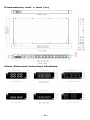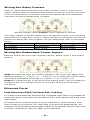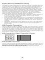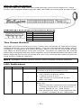
1
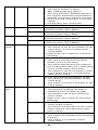
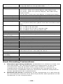
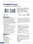
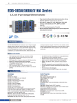
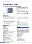
PT-7528 Series (24-Port Copper Models) Hardware Installation Guide Moxa PowerTrans Switch Second Edition, September 2014 2014 Moxa Inc. All rights reserved. P/N: 1802075280021 Package Checklist The Moxa PowerTrans switch is shipped with the following items. If any of these items are missing or damaged, please contact your customer service representative for assistance. • • • • • • • 1 Moxa PowerTrans switch USB cable (Type A male to Type B male) Protective caps for unused ports 2 rackmount ears CD-ROM with user’s manual and SNMP MIB file Hardware installation guide Warranty card Panel Layout 1. 2. 3. 4. 5. 6. 7. 8. 9. 10. System status LEDs Ethernet port LEDs Fast Ethernet port Fiber Ethernet interface module slot USB console port 10-pin terminal block for power inputs, and relay output Rack mounting kit Grounding screw USB storage port (ABC-02-USB-T) Reset button -2- Dimensions; unit = mm (in) Fiber Ethernet Interface Modules -3- Rack Mounting Use six screws to attach the PT switch to a standard rack. Rack Mounting Kit PT-7528 Side View NOTE Two additional rack-mount ears can be ordered as an option. Use them to secure the rear of the chassis in high-vibration environments. Wiring Requirements WARNING Safety First! • Be sure to disconnect the power cord before installing and/or wiring your Moxa PowerTrans Switch. • Calculate the maximum possible current in each power wire and common wire. Observe all electrical codes dictating the maximum current allowable for each wire size. • If the current goes above the maximum ratings, the wiring could overheat, causing serious damage to your equipment. Grounding the Moxa PowerTrans Switch Grounding and wire routing help limit the effects of noise due to electromagnetic interference (EMI). Run the ground connection from the ground screw to the grounding surface prior to connecting devices. Wiring the Power Inputs The PT-7528 switches support dual redundant power supplies: Power Supply 1 (PWR1) and Power Supply 2 (PWR2). The connections for PWR1, PWR2, and the RELAY are located on the terminal block. The front view of the terminal block connectors are shown below. -4- Wiring the Relay Contact Each PT-7528 switch provides two types of relay output, at the user’s option. Refer below for detailed instructions on how to connect the wires to the terminal block connector, and how to attach the terminal block connector to the terminal block receptor. Normal contact state without power applied to device The relay contact is used to detect user-configured events. Two wires are attached to the relay pins. The PT-7528 provides normal open and normal closed circuits at the user’s option. For pin definitions refer to the table below: Relay pin connection Pin 4 and 6 Pin 8 and 6 Power on state Closed circuit Open circuit Event trigger Open circuit Closed circuit Wiring the Redundant Power Inputs Each PT switch has two sets of power inputs: power input 1 and power input 2. STEP 1: Insert the dual set positive/negative DC wires into PWR1 and PWR2 terminals (+ pins 1, 7; - pins 3, 9), or insert the L/N AC wires into PWR1 and PWR2 terminals (L pins 1, 7; N pins 3, 9). STEP 2: To keep the DC or AC wires from pulling loose, use a screwdriver to tighten the wire-clamp screws on the front of the terminal block connector. Ethernet Ports Fast Ethernet RJ45 Twisted-Pair Cabling PT-7528 series Ethernet switches are equipped with many 10/100BaseTX ports that allow connection to standard CAT-5 STP cables with RJ45 male connectors. PT-7528 series products feature auto-negotiation, auto-polarity, and auto-crossover functions. For high EMC environment applications, we suggest using shielded twisted-pair cables to avoid EMC interference and to retain compliance with the IEEE 1613 standard. -5- Gigabit Ethernet 1000BaseTX Cabling The IEEE 802.3ab Gigabit Ethernet standard defines 1000 Mbps Ethernet communications over distances of up to 100 meters using all 4 pairs in category 5 (or higher) balanced unshielded twisted-pair cabling. For wiring guidelines, system designers and integrators should refer to the Telecommunications Industry Association (TIA) TIA/EIA-568-A wiring standard that characterizes minimum cabling performance specifications required for proper Gigabit Ethernet operation. To ensure reliable, error-free data communication, new and pre-existing communication paths should be verified for TIA/EIA-568-A compliance. • • • Data cable lengths should be as short as possible, ideally limited to 3 m (10 ft) in length. Copper data cables should not be used for inter-building communications. Power and data cables should not be run in parallel for long distances, and should be installed in separate conduits. Power and data cables should intersect at 90° angles when necessary to reduce inductive coupling. Optionally, shielded/screened cabling can be used. The cable shield should be grounded at one single point to avoid the generation of ground loops. USB Console Connection The PT-7528 series has one USB console port (type B connector), located on the top panel. Use the USB cable (provided in the product package) to connect the PT-7528’s console port to your PC’s USB port and install the USB driver (available in the software CD) on your PC. You may then use a console terminal program, such as Moxa PComm Terminal Emulator, to access the PT-7528’s console configuration utility. USB Console Port (Type B Connector) Pinouts Pin 1 2 3 4 Description D- (Data-) VCC (+5V) D+ (Data+) GND (Ground) USB Storage Connection The PT-7528 series has one USB storage port (type A connector) on the front panel. Use Moxa’s ABC-02-USB-T automatic backup configurator to connect the PT-7528’s USB storage port for configuration backup, firmware upgrade, or system log file backup. -6- ABC-02-USB Installation Plug the ABC-02-USB into the USB storage port of the Moxa PT-7528 series. We suggest attaching the ABC-02-USB to a wall with an M4 screw. USB Storage Port (Type A Connector) Pinouts Pin 1 2 3 4 Description VCC (+5 V) D- (Data-) D+ (Data+) GND (Ground) The Reset Button Depress the Reset button for five continuous seconds to load the factory default settings. Use a pointed object, such as a straightened paper clip or toothpick, to depress the Reset button. When you do so, the STATE LED will start to blink about once per second. Continue to depress the STATE LED until it begins blinking more rapidly; this indicates that the button has been depressed for five seconds and you can release the Reset button to load factory default settings. NOTE DO NOT power off the switch when loading default settings LED Indicators LED Color STATE GREEN State On Blinking RED On Description System has passed self-diagnosis test on boot-up and is ready to run. • 1 blink every sec: The switch is being reset • 1 blink every 2 sec: The switch is connected to the ABC-02-USB. The system failed self-diagnosis on boot-up. • RAM Test Fail / System Info. Read Fail / Switch Initial Fail / PTP PHY Error. (+ Green MSTR lit on : HW FAIL) • FW Checksum Fail / Uncompress Fail. (+ Green Coupler lit on: SW FAIL) -7- FAULT RED On PWR1 AMBER Off On Off PWR2 AMBER On Off MSTR/ GREEN HEAD On Blinking Off CPLR/ TAIL GREEN On Blinking Off One of the following situations exists: • The signal contact is open. • ABC Loading/Saving Failure. • The port has been disabled because the ingress multicast and broadcast packets exceed the ingress rate limit. • Incorrect loop connection in a single switch. • Invalid Ring port connection. The system is operating normally. Power is being supplied to the main module’s power input PWR1. Power is not being supplied to the main module’s power input PWR1. Power is being supplied to the main module’s power input PWR2. Power is not being supplied to the main module’s power input PWR2. One of the following situations exists: • The switch is set as the Master of the Turbo Ring, or as the Head of the Turbo Chain. • POST H.W. Fail (+Stat on and Fault blinking). One of the following situations exists: • The switch has become the Ring Master of the Turbo Ring. • The switch has become the Head of the Turbo Chain after the Turbo Ring or the Turbo Chain went down. • The switch is set as a member of the Turbo Chain and the corresponding chain port is down. One of the following situations exists: • The switch is not the Master of this Turbo Ring. • This switch is set as a member of the Turbo Chain. One of the following situations exists: • The switch’s coupling function is enabled to form a back-up path. • The switch is set as the Tail of the Turbo Chain. • POST S.W. Fail (+Stat on and Fault blinking) One of the following situations exists: • Turbo Chain is down. • The switch is a member of the Turbo Chain and the corresponding chain port is down. One of the following situations exists: • This switch has disabled the coupling function. • This switch is a member of the Turbo Chain. -8- FAULT + MSTR/HEAD + CPLR/TAIL STATE + FAULT + MSTR/HEAD + CPLR/TAIL Ports GREEN 1 to 24 AMBER M1 Ports 1 to 4 GREEN AMBER Rotate ABC-02-USB is importing/exporting Blinking files. Sequentially Blinking 2 blinks per sec: The switch is being discovered/located by MXview. On Blinking Off On Blinking Off On Blinking Off On Blinking Off Port’s 100 Mbps link is active Data is transmitting at 100 Mbps Port’s link is inactive Port’s 10 Mbps link is active Data is transmitting at 10 Mbps Port’s link is inactive Port’s highest speed link is active Data is transmitting at the highest speed Port’s link is inactive Port’s non-highest speed link is active Data is transmitting at non-highest speed Port’s link is inactive Specifications Technology Standards Protocols MIB Flow control Interface Fast Ethernet Gigabit Ethernet Console Port Storage port System LED Indicators IEEE 802.3 for 10BaseT IEEE 802.3u for 100BaseT(X) and 100BaseFX IEEE 802.3ab for 1000BaseT(X) IEEE 802.3z for 1000BaseX IEEE 802.3x for Flow Control IEEE 802.1D-2004 for Spanning Tree Protocol IEEE 802.1w for Rapid STP IEEE 802.1s for Multiple Spanning Tree Protocol IEEE 802.1Q for VLAN Tagging IEEE 802.1p for Class of Service IEEE 802.1X for Authentication IEEE 802.3ad for Port Trunk with LACP IGMP v1/v2, GMRP, GVRP, SNMPv1/v2c/v3, DHCP Server/Client, BootP, TFTP, SNTP, SMTP, RARP, RMON, HTTP, HTTPS, Telnet, SSH, Syslog, DHCP Option 66/67/82, EtherNet/IP, Modbus/TCP, LLDP, IEEE 1588 PTP V2, IPv6, NTP Server/Client, MMS MIB-II, Ethernet-like MIB, P-BRIDGE MIB, Q-BRIDGE MIB, Bridge MIB, RSTP MIB, RMON MIB Groups 1, 2, 3, 9 IEEE 802.3x flow control, back pressure flow control 10/100BaseT(X) or 100BaseFX (SC/ST connector) 10/100/1000BaseT(X), 1000BaseSX/LX/LHX/ZX (SFP slot, LC connector) USB-serial console (Type B connector) USB storage port (Type A connector) STAT, PWR1, PWR2, FAULT, MSTR/HEAD, CPLR/TAIL -9- Alarm Contact One relay output with current carrying capacity of 3 A @ 30 VDC or 3 A @ 240 VAC Optical Fiber (100BaseFX) Distance Multi-mode: 0 to 5 km, 1300 nm (50/125μm, 800 MHz*km) 0 to 4 km, 1300 nm (62.5/125μm, 500 MHz*km) Single-mode: 0 to 40 km, 1310 nm (9/125μm, 3.5 PS/(nm*km)) Min. TX Output Max. TX Output RX Sensitivity Power Input Voltage Multi-mode: -20 dBm; Single-mode: -5 dbm Multi-mode: -10 dBm; Single-mode: 0 dbm Multi-mode: -32 dBm; Single-mode: -34 dbm WV: 24/48 VDC (18 to 72 V) HV: 110/220 VDC/VAC (88 to 300 VDC and 85 to 264 VAC) Input Current Max. 0.741 A @ 24 VDC Max. 0.364 A @ 48 VDC Max. 0.147/0.077 A @ 110/220 VDC Max. 0.283/0.19 A @ 110/220 VAC Physical Characteristics Housing IP40 protection, metal case Dimensions 440 x 44 x 325 mm (17.32 x 1.73 x 12.76 in) (W x H x D) Weight 4900 g Installation 19” rack mounting Standards and Certifications Safety UL 508 Power Automation IEC 61850-3, IEEE 1613 Road Traffic NEMA TS2 Rail Traffic EN 50121-4 EMI FCC Part 15 Subpart B Class A, EN55022 class A Environmental Limits Operating Temp. -40 to 85°C (-40 to 185°F) Cold start of min. 100 VAC at -40°C Storage Temp. -40 to 85°C (-40 to 185°F) Ambient Relative 5 to 95% (non-condensing) Humidity. Warranty Warranty Period 5 years Details See www.moxa.com/warranty Rack Mounting Instructions 1. 2. Elevated Operating Ambient: If installed in a closed or multi-unit rack assembly, the operating ambient temperature of the rack environment may be greater than room ambient. Therefore, consideration should be given to installing the equipment in an environment compatible with the maximum ambient temperature (Tma) specified by the manufacturer. Reduced Air Flow: Installation of the equipment in a rack should be such that the amount of air flow required for safe operation of the equipment is not compromised. - 10 - 3. 4. 5. Mechanical Loading: Mounting of the equipment on the rack should be such that a hazardous condition is not achieved due to uneven mechanical loading. Circuit Overloading: Consideration should be given to the connection of the equipment to the supply circuit and the effect that overloading of the circuits might have on overcurrent protection and supply wiring. Appropriate consideration of equipment nameplate ratings should be used when addressing this concern. Reliable Grounding: Reliable grounding of rack-mounted equipment should be maintained. Particular attention should be given to supply connections other than direct connections to the branch circuit (e.g., use of power strips). NOTE The rackmount ears can be equipped on the front or rear of the PT-7528 switch. Restricted Access Locations • • This equipment is intended to be used in Restricted Access Locations, such as a computer room, with access limited to SERVICE PERSONAL or USERS who have been instructed on how to handle the metal chassis of equipment that is so hot that special protection may be needed before touching it. The location should only be accessible with a key or through a security identity system. External metal parts of this equipment are extremely hot!! Before touching the equipment, you must take special precautions to protect your hands and body from serious injury. Power Connection Warning You should always connect both power supplies when using this device, and disconnect both power supplies when this device is not in use. If only one power supply is connected, you could receive a hazardous electric shock by touching the unconnected terminals of the other power supply. All power connection wiring must be done by a qualified electrician and follow the National Electrical Code, ANSI/NFPA 70, and Canadian Electrical Code, Part I, CSA C22.1. An IEC certified or UL listed single-phase type circuit-breaker, rated for a maximum of 20 A, should be installed between main circuit and the device. Technical Support Contact Information www.moxa.com/support Moxa Americas: Toll-free: 1-888-669-2872 Tel: 1-714-528-6777 Fax: 1-714-528-6778 Moxa China (Shanghai office): Tel: +86-21-5258-9955 Fax: +86-21-5258-5505 Moxa Europe: Tel: +49-89-3 70 03 99-0 Fax: +49-89-3 70 03 99-99 Moxa Asia-Pacific: Tel: +886-2-8919-1230 Fax: +886-2-8919-1231 - 11 -