1
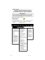
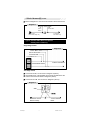
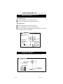
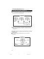
CA-640
Installation
Instructions
PROFESSIONAL INSTALLATION
STRONGLY RECOMMENDED
Installation Precautions:
Roll down window to avoid locking
keys in vehicle during installation
Avoid mounting components or
routing wires near hot surfaces
Avoid mounting components or
routing wires near moving parts
Tape or loom wires under hood
for protection and appearance
Use grommets when routing wires
through metal surfaces
Use a voltmeter for testing and
verifying circuits
Technical Support
For Authorized Dealers - (800) 421-3209
FCC COMPLIANCE
This device complies with Part 15 of the FCC rules and with RSS-210 of Industry
Canada. Operation is subject to the following two conditions:
1. This device may not cause harmful interference, and
2. This device must accept any interference received, including any interference that
may cause undesired operation.
Warning!
Changes or modifications not expressly approved by the party responsible for
compliance could void the user’s authority to operate the equipment.
1
CA-640.p65
1
10/20/03, 7:47 PM
System Layout
FOR MODULE FUSE SIZE AND POLARITY
LOCATIONS, REFER TO CHART ON PAGE 20.
IMPORTANT!!!
The module MUST be programmed before it will operate.
Refer to the programming instructions on pages 16-21.
System Layout Code Alarm CA-640TM
A = Advanced Harness
B = Basic Harness
C = Car Start Harness
Note: The wire connection sections will identify each wire with a number
(pin cavity) and a letter (harness), i.e.: 20/B = Wire 20, B (Basic)
Harness.
View from wire end:
1
2
10
11
1
3
4
12
2
5
13
3
6
7
8
9
1
2
3
4
5
14 15 16 13 14 15 16 17 18
4
6
7
11 12
1
2
19 20 21 22 23 24
8
9
10
7
8
3
4
5
6
9
10
External Antenna / Receiver Port
Advanced Harness
Basic Harness
Car Start Harness
1. Lock Switch (87a) (BLU/BLK)
1. Parking Light Output (WHITE)
1. HVAC2 Input(BLUE)
2. Factory Arm/RAP (-) (BLK/GRN) 2. Lock Motor Output (BLUE)
2. Battery (+12 v)(RED)
3. Unlock Switch (87a)(GRN/BLK) 3. Dome Light Output (BLK/WHT)
3. Ignition2Output(-)(PK/WHT)
4. HVAC1Output(-)(ORG)
4. Factory Disarm (-) (LT.GRN/BLK) 4. Battery (+12v) (RED)
5. HVAC2Output(+)(ORG/WHT)
5. Unused
5. Ground (BLACK)
6. Unused
6. Starter Key (+) (VIOLET/RED)
6. Unused
7. Brake Input(+) (BROWN)
7. Unused
7. Ignition 1 Input/Output (+) (PINK)
8. Starter Motor (+)(VIOLET)
8. Neutral Safety (BLK/WHT)
8. Trunk Pin Input (-) (BLUE)
9. Tach In (VIOLET/WHT)
9. Trunk Switch (87a) (TAN/RED) 9. Unused
10. Active Out (-) (BLU/BLK)
10. AUX 1 (-) 500ma (RED/WHT) 10. Door Trig. 10k pull-up (YEL/WHT)
11. AUX 2 (-) 500ma (BLU/WHT) 11. Ext. Start Trig./Ext. Lt. Touch (WHT/BLU)
12. AUX 3 (-) 500ma (GRN/WHT) 12. Unused
13. Trunk Motor Output (TAN)
13. AUX 4 (-) 500ma (YL/GRN)
14. Unlock Motor Output (GREEN)
14. Armed Output (-) (ORANGE)
15. Ext. Sensor Input (-) (BLK)
15. Siren Feed (RED)
16. Unused
16. Siren Drive (-) 1 Amp (BLACK)
17. Disarm/Override Button (Ground) (PLUGIN)
18. Disarm/Override Button Input (PLUGIN)
19. Hood Pin Input (GRAY)
20. Door Trigger Input (GRN/VT)
21. Horn Relay Drive (-) 500ma (BRN/BLK)
22. LED 2 (Red) (PLUGIN)
23. LED 1 (Black) (PLUGIN)
24. SecondDoorUnlock(-)500ma(BLU/GRN)
2
CA-640.p65
2
10/20/03, 7:47 PM
1. Basic Harness (B)
IMPORTANT!!!
• Remove fuses from Module before installation.
• Solder and tape all connections.
1/B
Parking Light Output (16 AWG) (WHITE)
Locate the vehicle parking light wire.
Verification: This wire will register either positive voltage or ground
when the parking lights are turned on. Voltage does not vary when
dimmer switch is adjusted. Refer to the Vehicle Wire Color and
Location Chart for the wire color, polarity, and location.
Connect the 1/B wire to the parking light wire.
IMPORTANT!
After installation, set the polarity of this circuit by moving the
fuse inside of the control module to positive (+) or negative (-).
2/B
1/A
Lock Motor Wire (16 AWG) (BLUE)
Lock Switch Wire 87A (16 AWG) (BLUE/BLACK)
14/B Unlock Motor Wire (16 AWG) (GREEN)
3/A Unlock Switch Wire 87A (16AWG) (GREEN/BLACK)
24/B Second Door Unlock (16 AWG -) (BLUE/GREEN)
IMPORTANT!
After installation, set the polarity of this circuit by moving the
fuse inside of the control module to positive (+) or negative (-).
Type 1:
Positive 3-wire door lock system Polarity Fuse = Positive (+)
Single-stage unlock
Diagram 1
Connect the 2/B wire to the vehicle
lock wire.
Fused + 12v
Connect the 14/B wire to the vehicle
unlock wire.
Two-stage unlock
24/B
Connect the 2/B wire to the vehicle
lock wire.
Use a SPDT relay (not supplied)
and connect the 24/B wire to the
vehicle unlock wire as shown in
Diagram 1.
To vehicle unlock wire
3
CA-640.p65
3
10/20/03, 7:47 PM
1. Basic Harness (B), cont’d
Refer to Diagram 2 to connect to the vehicle’s drivers unlock wire.
Diagram 2
Wires from control module
14/B
3/A
Unlock
Unlock Motor
Switch
From driver’s
Door Unlock Relay only
Cut
To driver’s
Door Motor only
Type 2: Positive 5-Wire Door Lock System
Polarity fuse = Positive (+)
Single-Stage Unlock
Diagram 3
Unlock Motor 14/B
Unlock Switch 3/A
Lock Motor 2/B
Lock Switch 1/A
Vehicle Master Switch
To Door Lock Motors
Two-Stage Unlock
Connect wires 2/B, 1/A as shown in Diagram 3 (above).
Use a SPDT relay ( Not Supplied) and connect the 24/B wire to the
vehicle’s unlock wire as shown in Diagram 4 (below).
Connect wires 14/B, 3/A as shown in Diagram 2 (above).
Diagram 4
Fused +12v
24/B
From Door Unlock
Switch or Relay
To Door Unlock
Motor
4
CA-640.p65
4
10/20/03, 7:47 PM
1. Basic Harness (B), cont’d
Type 3: Negative 3-Wire Door Locking System
Polarity Fuse = Negative
Single-stage unlock
Connect the 2/B wire to the vehicle lock wire.
Connect the 14/B wire to the vehicle unlock wire.
Two-stage unlock
Connect the 2/B wire to the vehicle lock wire.
Connect the 24/B wire to the vehicle unlock wire.
Use a SPDT relay (not supplied) and refer to Diagram 5 to connect
to the vehicle’s driver’s unlock wire.
Diagram 5
Fused + 12v
Fused + 12v
14/B
From Driver’s
Door Only
Unlock Switch
or Relay
To Driver’s
Door Unlock
Motor
Cut Here
Type 4: Vacuum Door Lock System
Polarity Fuse = Positive
Note: Two-stage unlock will not work with this type of system.
Diagram 6
5
CA-640.p65
5
10/20/03, 7:47 PM
1. Basic Harness (B), cont’d
Type 5: Resistor Door Lock system
Polarity Fuse = Positive/Negative
Note: Refer to Vehicle Wire Color and Location Chart for correct
polarity. Move the fuse inside of the control module to positive or
negative polarity.
Single Stage Unlock
Diagram 7
Two-Stage Unlock
Connect the 2/B wire as shown in Diagram 7 (above).
Connect the 24/B wire as shown in Diagram 8 (below).
Connect the 14/B wire as shown in Diagram 9 (below).
Diagram 8
Ground for negative
polarity system
+12v fused for
positive polarity
system
24/B
+12v fused
Diagram 9
+12v fused
To vehicle door lock module
Ground for positive
polarity system
+12v fused for
negative polarity
system
14/B
Cut
From Switch
Side of Driver’s
Door Unlock
To Driver’s
Door Unlock
Motor
6
CA-640.p65
6
10/20/03, 7:47 PM
1. Basic Harness (B), cont’d
3/B
Courtesy Light Output (16 AWG) (BLACK/WHITE)
Locate the vehicle courtesy light wire.
Verification: This wire is usually the door pin switch wire. Refer to
testing procedure in 20/B to determine the correct polarity of the
courtesy light system.
Connect wire to the courtesy light wire.
IMPORTANT!
After installation, set the polarity of this circuit by moving the
fuse inside of the control module to positive (+) or negative(-).
4/B
Main Power (14 AWG) (RED)
Connect the 4/B wire to the vehicle main power wire at the ignition switch.
Verification: This wire registers voltage through every position of
the ignition switch.
5/B
Chassis Ground (14 AWG) (BLACK)
Connect the 5/B wire to a solid chassis ground point. Scrape
away paint from the grounding point to ensure a good connection.
Note: Do not ground the 5B wire with any other vehicle components.
6/B
8/B
Starter Input Key Side (14 AWG) (VIOLET/RED)
Starter Output Motor Side (14 AWG) (VIOLET)
Locate the vehicle starter wire.
Verification: This wire registers voltage only when the key is turned
to the START position.
Cut the vehicle starter wire in half.
Verification after starter wire is cut:
• KEY SIDE of starter wire registers voltage when the key is turned
to the START position.
• MOTOR SIDE of starter wire registers no voltage.
Connect the 6/B wire to the KEY SIDE of the vehicle starter wire at
the ignition switch harness.
Connect the 8/B wire to the MOTOR SIDE of the vehicle starter wire.
7/B
Ignition 1 Input/Output (14 AWG+) (PINK)
Connect 7/B wire to the vehicle ignition wire at the ignition switch.
Verification: This wire registers voltage when the key is turned to
the ON (or RUN) position. The voltage does not drop out when the
key is turned to the START (or CRANK) position.
10/B Door Trigger 10K Pull-up Resistor (20 AWG) (YEL/WHT)
For vehicles with a door input battery saver mode (i.e., Ford Windstar,
Lincoln LS, Cadillac DeVille):
Connect the 16/A wire to a fused constant 12 volt source.
Note: An internal 10k resistor will prevent the door input from going
into battery saver mode to prevent alarm falsing.
7
CA-640.p65
7
10/20/03, 7:47 PM
1. Basic Harness (B), cont’d.
11/B
External Start Trigger/ Lite Touch Input (20 AWG +/-)
(WHITE/BLUE)
This wire will activate the Car Start System or provide an external
warn away input when a positive/negative pulse is applied to it
from an external device. Refer to option programming
IMPORTANT!
After installation, the polarity for this circuit must be
set in Option Bank 9, Feature 2 (page 20).
13/B Trunk Release Output (16 AWG) (TAN)
Locate the vehicle trunk release wire.
Verification: Refer to the Vehicle Wire Color and Location Chart
for the wire color, polarity, and location.
Connect the 13/B wire to the vehicle trunk release wire.
Note: If the trunk release system is 5-wire type, refer to wire 9/A
(Advanced Harness).
IMPORTANT!
After installation, set the polarity of this circuit by moving the
fuse inside of the control module to positive (+) or negative(-).
15/B, 16/B
Siren Installation (20 AWG)
If you are installing a siren:
Mount siren with bell housing facing down.
Use at least two (2) screws to secure siren to mounting location.
Connect siren; BLACK wire to 16/B BLACK Siren Drive.
Connect siren; RED wire to a 15/B RED Ssiren Feed.
Note: For Multi-Tone sound reverse leads
17/B, 18/B
Emergency Override Button (20 AWG-)
Find a mounting location for the override button that is not easily
seen or openly accessible. There must be at least 1" clearance
behind the location.
Drill a 9/32" hole and mount the button.
19/B Hood Safety/Glow Plug Input (20 AWG -) (GRAY)
Install the supplied pin switch and attach the 19/B wire.
Verification: When connected, the 19/B wire will register ground
when the vehicle hood is opened.
This wire can be used as a (NEG) glow plug input , diode isolate
if used for both circuits
8
CA-640.p65
8
10/20/03, 7:47 PM
1. Basic Harness (B), cont’d.
20/B Positive/Negative Door Input (20 AWG) (GREEN/VIOLET)
Connect the 20/B wire to the vehicle pin switch or courtesy light circuit.
Verification - Refer to Vehicle Wire Color and Location Chart for
circuit type and location, or verify the vehicle wire using the
following guideline:
• Positive Systems - Target wire registers voltage
when any door is opened.
• Negative Systems - Target wire registers ground
when any door is opened.
Important!
After i nstallation, select the polarity of t his circuit i n programming
Option Bank 9, Feature 1 (factory default = negative), page 20
NOTE:
FOR POSITIVE SYSTEMS, TEMPORARILY CONNECT THE 20/B WIRE TO GROUND
IN ORDER TO ACCESS THE PROGRAMMING MODE.
CHANGE OPTION BANK 9/FEATURE 1 TO POSITIVE POL ARITY (PAGE 20).
21/B Horn Relay Drive 500mA (20 AWG -) (BROWN/BLACK)
Locate the vehicle horn wire.
Verification: This wire will register
either positive or ground when the
horn is pressed.
Connect the 21/B wire to the vehicle
horn wire if the system is negative.
If the system is positive, use a SPDT
Relay (not supplied) and connect the
21/B wire to the vehicle horn wire as
shown (Diagram 10).
Diagram 10
+12 Volts
21/B
To Horn Wire
22/B LED2 (20 AWG+)
23/B LED1 (20 AWG-)
Locate a visible section of the dash with 1" clearance behind
the location.
Drill a 9/32" hole and snap the Status Indicator into place.
Connect the Status Indicator Red Wire to the 22/B LED2 wire.
Connect the Status Indicator Black Wire to the 23/B LED1 wire.
9
CA-640.p65
9
10/20/03, 7:47 PM
2. Advanced Harness (A)
2/A Factory Alarm Arm (20 AWG-) (BLACK/GREEN)
Connect the 2/A wire to the vehicle anti-theft arm wire (if
equipped).
Verification: This wire will register ground when the driver’s door
is locked with the key. Refer to Vehicle Wire Color and Location
Chart for specific color and polarity information.
2/A Retained Accessory Output (20 AWG-) ( BLACK/GREEN)
Diagram 11
This wireon also has the
ability to go active after the
ignition has been turned off
for 1 minute or until the door
has open. This is a selectable
option please refer to option
programming on page ??.
Option Bank 6, Feature 4
+12v fused
2/A BLACK/
GREEN
To vehicles
Accessory wire
Use a SPDT relay (not supplied) and connect the 2/A wire as shown
(Diagram 11) this will keep the accessories active
(i.e.Radio, Windows ,Etc)
4/A
Factory Alarm Disarm (20 AWG-) (LT.GREEN/BLACK)
Connect the 4/A wire to the vehicle anti-theft disarm wire (if equipped).
Verification: This wire will register ground when the driver’s door is
unlocked with the key. Refer to Vehicle Wire Color and Location
Chart for specific wire color and polarity information.
8/A
Trunk Pin Input (20 AWG-) (BLUE)
Connect the 8/A wire to the vehicle’s wire that registers ground
when the trunk is opened. Pin Swicth may be required
9/A
Trunk Switch 87A (20 AWG) (TAN/RED)
This wire is the normally closed pin (87A) for the internal trunk
release relay. If the vehicle has a 5-wire type trunk release it will be
necessary to cut that wire and connect 9/A to the switch side of that
wire.
Note: See 13/B description (Basic Harness).
10/A Headlight / Aux 1 500ma (20 AWG -) (RED/WHITE)
Locate the vehicle headlight wire.
Verification: This wire will register either positive voltage or ground
when the headlights are turned on.
Connect the 10/A wire to the vehicle headlight wire
if the system is negative. (LOW CURRENT ONLY)
10
CA-640.p65
If the system is positive, use a SPDT relay (not supplied) and
connect the 10/A wire as shown (Diagram 11).
10
10/20/03, 7:47 PM
2. Advanced Harness (A), cont’d
10/A Cont. Headlight / Aux 1 500ma (20 AWG -) (RED/WHITE)
Diagram 11.5
If wire in the vehicle tests
positive, use a SPDT relay
(not Supplied) and connect as
diagram 11.5 as shown
+12v fused
10/A Headlight
wire or
11/A defrost
wire
To vehicle headlight
or defrost wire
11/A Rear Defrost Output/Aux 2 500ma (20 AWG -) (BLU/WHITE)
Locate the vehicle rear window defrost wire.
Verification: This wire will register either positive voltage or ground
when the rear defroster is turned on.
Connect the 11/A wire to the vehicle defrost wire if the system
is negative.
If the system is positive, use a SPDT relay (not supplied) and
connect the 11/A wire as shown (Diagram 11.5).
NOTE: If using Turbo Timer feature, the 11/A Aux 2 wire is used to
control a relay to power the Ignition 1 wire when the Turbo Timer is
activated. See below for relay diagram.
11/A Turbo Timer Ignition 1 Output 500ma (20 AWG)(BLU/WHITE)
This wire is used to
energize a relay as shown
in diagram 11.6 (below) that
powers the Ignition 1 wire in
the vehicle during Turbo
Timer activation.
Diagram 11.6
12V+
Constant
11/A
Aux 2
12V+Constant
To Second
Ignition /
Heater Wire
To Ignition1
7/B
To 7/B
Ignition 1
Input/Output
Input/Output
12/A Aux - 3 500ma (20 AWG - ) (GRN/WHT)
This wire provides a 500ma negative output capable of driving
relays. For control of optional accessories (i.e.: power window/
sunroof, etc.)
13/A Aux - 4 500ma (20 AWG - ) (YELLOW/GREEN)
This wire provides a 500ma negative output capable of driving
relays for control of optional accessories (i.e.: power window/
sunroof, etc.)
11
CA-640.p65
11
10/20/03, 7:47 PM
3. Car Start Harness (C)
14/A Armed Output (20 AWG -)(ORANGE) 500mA
This wire will show a ground when the security system is armed.
15/A External Sensor Input (20 AWG -) (BLACK)
This wire is a ground input for an external sensor. Connect this
wire to the negative output of the external sensor.
2/C
Battery (#14 AWG) (RED)
Connect 2/C to a main power wire at the ignition switch, preferably
to a wire other than the 4/B main power connection.
3/C
Ignition 2 Output (14 AWG-) (PINK/WHITE)
30 Amp Fused Relay Battery Feed (12 AWG) (RED)
Note: The 3/C wire is the ground trigger to an external Ignition 2
output relay.
Connect the external relay PINK/WHITE output wire to the Ignition
2 wire in the vehicle.
Connect the external relay 30 amp fused RED wire to a constant +12 volt
battery source, usually found at the vehicle ignition switch
4/C
HVAC1 Output (14 AWG -) (ORANGE)
30 Amp Fused Relay Battery Feed (12 AWG) (RED)
Note: The 4/C wire is the ground trigger to an external HVAC 1
output relay.
Connect the external relay PINK/WHITE output wire to the Ignition
2 wire in the vehicle.
Connect the external relay 30 amp fused RED wire to a constant +12 volt
battery source, usually found at the vehicle ignition switch
5/C
1/C
HVAC 2 Output (14 AWG+) (ORANGE/WHITE)
HVAC 2 Polarity Input (14 AWG) (BLUE)
Note: Use these wires if the vehicle requires connection to a
second heater/AC circuit for the vehicle to operate properly during
remote start.
Connect the 5/C HVAC 2
output wire to the second
heater/AC wire at the ignition
switch.
Connect the 1/C wire to a
main power wire at the
ignition switch, preferably to
a wire other than the 4/B
main power connection.
Third Ignition or Third
HVAC Connection
To PINK 7/B
or ORANGE
/WHITE 5/C
12V+
Constant
10/C
Active
Output
To Third
Ignition /
Heater Wire
To Third
Ignition /
Heater Wire
12
CA-640.p65
12
10/20/03, 7:48 PM
3. Car Start Harness (C), cont’d
7/C
Brake Input / Glow Plug Input (20 AWG+) (BROWN)
Connect the 7/C wire to the vehicle brake light wire.
Verification: This wire registers positive voltage when the brake
pedal is pressed.
This wire can be used as a (POS) Glow plug input.,
diodeisolate if used for both circuits
8/C
Neutral Safety Switch (20 AWG) (BLACK/WHITE)
NOTE: The following connections are required to ensure proper
operation of the system.
Negative systems:
Connect the 8/C wire to the vehicle wire at the shifter that will
show ground when in park or neutral, and voltage in all other
positions.
Positive systems:
Connect the 8/C wire to the vehicle wire at the shifter that
will show 12 volts when in park or neutral, and no voltage in
all other positions.
Note: This wire must be hooked up correctly for Turbo Timer option
to work. Refer to Programming Option Bank 9/ Feature 3 to select
polarity
9/C
Tach Input (-) (VIOLET/WHITE)
Connect the 9/C wire to wire at negative side of the vehicle
ignition coil or fuel injector.
Verification: Refer to Vehicle Wire Color and Location Chart for
the wire color and location, or test using the following procedure:
1. Set voltmeter to AC VOLTS.
2. Attach positive lead of meter to a constant 12-volt source.
3. Attach negative lead of meter to the wire to be tested.
4. Start the engine.
5. Have someone press on the gas pedal slightly as you monitor
the meter. If connected to the correct wire, the voltage reading
will increase as the engine’s RPM increases.
IMPORTANT!
If this wire is not connected, over-rev shut-off is disabled.
13
CA-640.p65
13
10/20/03, 7:48 PM
3. Car Start Harness (C), cont’d
10/C Active Output (20 AWG -) (BLUE/BLACK)
Connect the 10/C wire to add-on relays as described in Diagram
14, or to an optional component requiring a ground signal when
the vehicle is running via remote start.
Diagram 14
Diodestripeshould
face toward
InstallDiodesHere
10/C WIRE
Note: If you are connecting the 10/C wire to more than one relay,
install 1-amp blocking diodes (1N4001 or equivalent) as shown in
the Diagram 14.
Interrupting a Sensor or Component while the Vehicle is running
via Remote Start
Use an SPDT relay (not supplied) and connect as shown in
Diagram 15.
Diagram 15
Constant 12V+
10/C WIRE
Cut Here
FromSensor
SensorTriggerWire
To Alarm
14
CA-640.p65
14
10/20/03, 7:48 PM
4. System Power-Up and Programming
A. System Power-Up
1. All connections must be secure and well insulated.
2. Insert fuses inside of the control module in their respective slots.
3. Plug in DNA/fuse cover on top of the control module.
4. Turn vehicle ignition on.
5. Plug in 24-pin Basic Harness followed by the 16-pin Advanced
Harness and 10-pin Car Start Harness.
6. Plug in 4-pin external antenna receiver into the 4-pin port below
the 16-pin Advanced Harness.
7. Turn vehicle ignition off.
B. Remote Transmitter Programming
Note: Each system module has eight “slots”, or memory locations, to
store transmitter codes, giving it the ability to operate from up to
eight transmitters. For proper operation, a transmitter code must
be stored into each memory slot. When using less than eight
transmitters, follow the suggested programming parameters:
• One Remote Transmitter - Program eight (8) times
• Two Remote Transmitters - Program each transmitter four
(4) times
• Three Remote Transmitters - Program two transmitters
three (3) times, and the remaining transmitter twice.
1. Open the driver’s door.
1.a. The 20/B wire must initially see a ground to access
programming.
2. Turn vehicle ignition on.
3. Press and hold emergency override button.
After 10 seconds, the siren or horn will sound three (3) times. This
indicates that the unit has entered the transmitter programming mode.
4. Release the button.
5. Press the LOCK button on the remote transmitter to be
programmed.
The siren or horn will sound once, indicating that the system has
“learned” that remote transmitter.
6. Repeat step 5 for any additional transmitters or transmitter codes.
7. To continue to the Options Programming mode, go to step 2 of
Programming Selectable Options (next page). Otherwise, turn
the vehicle ignition off to exit the programming mode. Test all
remote transmitters to ensure that they work properly by toggling
the LOCK and UNLOCK buttons. Do not press the START button
until programming the tach signal (page 18).
15
CA-640.p65
15
10/20/03, 7:48 PM
4. System Power-Up and Programming, cont’d
C. Programming Selectable Options
LOCK
UNLOCK
Press to Turn
Press to Restore
Selected
All Settings to
Feature
Factory Defaults
FIND/PANIC
On /Off
Press to
Advance to Next
Setting
Note: Transmitters must be programmed prior to these steps.
1. Repeat steps 1-4 of Remote Transmitter Programming
(previous page).
2. Press and release the emergency override button.
The horn or siren will sound four (4) times. This indicates that the
unit has entered the Alarm Options (Option Bank 1).
3. Press the FIND/PANIC button to advance to the next feature.
The siren or horn will sound a number of times to indicate the
number of the option.
4. Press the LOCK button to turn the option on or off. The vehicle
status indicator on the dashboard indicates whether an option
is on or off.
• If the selected option is ON, the indicator will light.
• If the selected option is OFF, the indicator will turn off.
• The status indicator will turn on or off when an option is changed.
5. When changes are complete, press and release the emergency
override button to continue to the next option bank. (Siren or horn
will sound five (5) times.)
6. To reset all options back to factory defaults, press the UNLOCK
button.
Note: Installer Option bank will never reset.
7. Turn ignition off to exit programming.
See Options Chart on pages 19 - 20.
16
CA-640.p65
16
10/20/03, 7:48 PM
4. System Power-Up and Programming, cont’d
D. Adjusting the IT-sTM (Interior Theft Sensor)
The IT-sTM is factory pre-set at a moderate sensitivity level and has
two adjustment points: Lite-Touch and Full Shock.
Adjusting Lite-Touch Sensitivity:
1. To program the sensitivity of the lite touch trigger, simply enter into
the alarm options bank, then advance to the Lite Touch Adjustment.
Once in the Lite Touch Adjustment option, use the LOCK button of
the transmitter to increase, and the UNLOCK button to decrease the
sensitivity.
2. To verify the sensitivity, strike the vehicle (while in programming)
with the amount of force you feel is acceptable for a lite touch
trigger. If the system chirps, it will recognize that force; otherwise
increase or decrease to obtain proper sensitivity.
Adjusting Full-Shock Sensitivity:
1. To program the sensitivity of the full trigger simply enter into the
alarm options bank, then advance to Full Shock Adjustment. Once
in the Full Shock Adjustment option, use the LOCK button of the
transmitter to increase and the UNLOCK button to decrease
sensitivity.
2. To verify the sensitivity, strike the vehicle (while in programming)
with the amount of force you feel is acceptable for a full trigger. If
the system chirps, it will recognize that force; otherwise increase or
decrease to obtain proper sensitivity.
Note:
There are 64 levels of adjustment in each option. Once the
highest/lowest sensitivity is achieved, the siren/horn will
sound an extended pulse to notify that you are at the end of
the scale. Decreasing sensitivity one more step from the
lowest end of the scale will shut that zone off.
E. Programming the Tach Signal
Note: Skip this step if the vehicle does not have a tach wire or if this
unit will be programmed to operate without connection to the tach wire.
1. Open the vehicle hood (hood pin switch must be installed to
program tach).
2. Following the steps in Section C (Programming Selectable
Options), access Option Bank 9 / Feature 7 (page 20).
3. Start the vehicle with the key, and allow the engine to come to a
normal idle (5-10 seconds).
The unit will chirp the Siren/Horn and flash the parking lights every
three (3) seconds to indicate that it has learned the current idle speed.
17
CA-640.p65
17
10/20/03, 7:48 PM
4. System Power-Up and Programming, cont’d
F. Programming Options
Default settings in BOLD
OPTION
DESCRIPTION
Option Bank 0 - 3 Chirps (Learn Transmitters)
Option Bank One - 4 Chirps (Alarm Options)
1. Lite Touch Adj.
2. Full Shock Adj
3. Passive Starter Kill
4. Passive Arming
5. Passive Locks
6. Confirmation Chirps
7. Extended Horn Pulse
STATUS INDICATOR
ARM raises sensitivity: DISARM lowers sensitivity
ARM raises sensitivity: DISARM lowers sensitivity
Engages starter kill after one minute
Alarm automatically arms 60 sec.
after ignition is turned off
Automatic ly Locks Doors After 60 Sec.
(1) Yes (2) No confirmation chirps
Extends the horn output time
ON
ON
OFF
OFF
OFF
ON
ON(1) OFF(2)
OFF
ON
Option Bank Two - 5 Chirps (Convenience Options)
1. illuminated Exit
2. Personalized Transmitters
3. Real Panic Horn Output
4. Trunk Output timing
5. Noise Control
6. TurboTimer
Dome goes active when ignition key is turned off ON
Refer to pg ?? for reference
ON
(1) Random pulsed (2) Steady pulsed output
ON(1)
(1) 20 seconds latched (2) Push and ho ld
ON(1)
Alarm will (1) sound for five 30-sec. cycles,
ON(1)
then ignore trigger or (2) Sound continuously when triggered
Enables Turbo Timer Option
ON
OFF
OFF
OFF(2
OFF(2)
OFF(2)
OFF
Option Bank Three - 6 Chirps (Keyless Options)
1. Ford “Slam Lock” Option
2. Double Pulse Unlock
3. Ignition Triggered Lock
4. Ignition Triggered Unlock
5. Delayed Door Lock
6. Extended Locks
Delays door lock time for Ford unlock disable
Unit Provides 2 pulses when unlocked
Doors lock when all doors are closed and
ignition is turned on
Doors l ock when all doors are closed and
ignition is turned off
3 sec. delay locking for theater dimming
Lock duration is (1) 5 sec. or (2) .6 sec.
ON
ON
ON
OFF
OFF
OFF
ON
OFF
ON
ON(1)
OFF
OFF(2)
Option Bank Four - 7 Chirps (Car Start Options)
1. Tach Mode
2. Blind Crank
3. Adjustable Crank Time
4. Diesel Mode
5. RunTime
6. Lock After Start
7. 1 Button Start
8. Ignore Dome After Start
(1) Use blind crank (2) Use Tach input
ON
(1) Crank average (2) Adjustable
ON
Refer to Table 1.2 on pg. 20, LOCK advances to next time
15 Sec Delay before Crank
ON
(1) 25 Minutes (2) 12 Minutes
ON(1)
Relocks the doors after Remote Start
ON
ON(1)
(1)1 button Remote Start
(2)2 Button Remote Start
Door Trigger Ignored for 1 min. After Start
ON
18
CA-640.p65
18
10/20/03, 7:48 PM
OFF
OFF
OFF
OFF (2)
OFF
OFF(2)
OFF
4. System Power-Up and Programming, cont’d
Option Bank Five - 8 Chirps (AUX Options)
1. Auxiliary 1 Adjustment
2. Auxiliary 2 Adjustment
3. Auxiliary 3 Adjustment
4. Auxiliary 4 Adjustment
Aux. Adjust
Time Table
# of Chirps
1
Refer to Table 1.1 ARM Advances to next time
Refer to Table 1.1 ARM Advances to next time
Refer to Table 1 .1 ARM Advances to next time
Refer to T able 1.1 ARM Advances to next time
TBL 1.1
Duration
5
Push & Hold
500ms
5 Sec
10 Sec
20 Sec
6
30 Sec
2
3
4
OPTION
# of Chirps
Duration
7
11
60 Sec
5 Min
10 Min
20 Min
60 Min
12
Latched
8
9
10
DESCRIPTION
Option Bank Six - 9 Chirps (Installer Options)
STATUS INDICATOR
1. Door Trigger Polarity
(1) Positive (2) Negative
2. External Start Trigger
(1) Positive (2) Negative
3. Neutral Safety Input
(1) Positive (2) Negative
4. Retained Accessory Power (1) RAP (2) Factory Arm
5. External Lite Touch
(1) Lite Touch Input (2) External Start Trigger
6. E Code Entry
Coded Override - Refer to Pg. 21 for instructions
7. TachLearn
Tach Programming (HoodOpen, StartwithIgnitionkey)
Adjustable
Crank
Table
# of Chirps
1
2
3
4
5
6
7
ON(1)
ON(1)
ON(1)
ON(1)
ON(1)
ON
OFF(2)
OFF(2)
OFF(2)
OFF(2)
OFF(2)
OFF
Table 1.2
Duration
0.74 Sec
0.87 Sec
1.0 Sec
1.1 Sec
1.2 Sec
1.4 Sec
1.5 Sec
15A
15A
20A
15A
20A
20A
5A
19
CA-640.p65
19
10/20/03, 7:48 PM
5. Selectable Coded Override
How to use E-Code
E-Code is a alternate method of emergency overriding and will
take the place of the push-button when selected. The factory preset
for this option is 1111 and can be programmed with any
combination of numbers 1-9 making sure to use all 4 digits.
Programming the 4-digit E-Code:
1. To program a 4-digit code, simply enter into the installer options
bank, then advance to the E-Code option (Option Bank 9/Feature6).
Once at the E-Code option press LOCK to turn the feature ON (LED
ON).
2. To enter your choice for a code, push the override button the number
of times that correspond with the first digit of your code finalizing
with a push and hold (the hold counts as an entry). The system will
confirm acceptance of the code by chirping and flashing the LED
the number just programmed into the system. At this time, you can
repeat the step for the following 3 digits.
Example: If you desired code is 2345, push then push and hold for
digit 2, wait for system to chirp twice. Next push twice then push and
hold for digit 3, wait for system to chirp 3 times etc.
3. Once all 4 digits are entered to your satisfaction, either advance
back to the first installer option if necessary or exit programming. If
at any time during the code entry process you decide to exit the
process, the system will default back to its previously learned code
or the factory default.
Entering the 4-digit E-Code for overriding:
1. In the case that a remote control is lost and the system must be
overridden, the user will have to enter their previously programmed
4-digit code by using the ignition key and the hidden override
button.
2. To enter your first digit, turn the key to the ON position and push the
override button the number of times that correspond with the first
digit of your code then turn the key off.
3. Turn the key back to the ON position and push the override button
the number of times that correspond with the second digit of your
code and turn the key off.
4. Repeat this procedure until all 4 digits are entered, system will
disarm upon turning ignition off after 4th digit.
20
CA-640.p65
20
10/20/03, 7:48 PM
6. System Testing
1. Follow each instruction below.
2. Verify that the CA-640 operates as indicated under
each instruction.
3. Check the appropriate wire connections and/or fuses if the unit fails
to perform a specific function. Also check that any options
pertaining to the function are programmed properly.
Remote Start Operation
Press and hold START for 2 seconds.
1. Unit will chirp 4 times if tach is not yet learned or vehicle has not
been manually started if in Blind Crank Timing Mode.
2. Unit will chirp two (2) times if the neutral safety input does not see
ground.
3. Unit checks to see if hood is open.
If so, parking lights flash two (2) times
and vehicle will not start.
4. Unit checks to see if brake is pressed.
If so, parking lights flash two (2) times
and vehicle will not start.
If the above conditions are not present:
1. Parking lights flash once.
2. Factory alarm (if equipped) is turned off.
3. Factory transponder systems (if equipped)
are interfaced (active output is activated).
4. Interior Sensor is disabled.
5. Vehicle ignition turns on.
6. Heater/AC are powered.
7. Vehicle starter begins to crank (heater/AC power shuts off while
vehicle starter is cranking).
8. Vehicle successfully starts.
9. Doors lock.
10.Vehicle will shut off if hood is opened, brake is pressed, or if engine
reaches 3 times its idle speed (Tach Sense Mode only). Vehicle will
also shut off if alarm is triggered.
11.Parking lights stay on for duration of run time.
12.Heater/AC is powered for duration of run time.
13.Vehicle runs for 12 or 25 minutes depending on setting of option.
* A two button start sequence (press LOCK, then press START within 2 seconds) can
be set in
Programming Option Bank 4/ Feature 7 (page 19).
21
CA-640.p65
21
10/20/03, 7:48 PM
6. System Testing, cont’d
Start output configuration:
Tach Sense Mode
If Tach input wire is connected and Tach Sense Mode is enabled,
the starter will crank until the tach signal indicates that the vehicle
has started, or 4 seconds have passed. After 4 seconds, starter,
heater/AC, and ignition will shut off. The unit will pause 5 seconds,
then attempt to start the vehicle again. The start sequence will be
attempted 5 times before aborting.
Blind Crank Timing Mode
If Blind Crank Timing Mode is enabled, the module will average the
last eight key starts to determine crank time. The vehicle must be
started at least 4 times with the key to initialize an average. The
module will use this average as an assumed crank time.
Adjustable Crank Time
If No Tach Mode is enabled, the starter will crank for 1 of 7 preselected times . The unit will “assume” that the vehicle has started.
You must select the time desired for each specific vehicle refer, to
pg. 20 (table 1.2) for the time table
Note: In Blind Crank Timing or Adjustable Crank modes, over-rev
protection is disabled if selected.
Press and hold START while vehicle is running via remote start
1. Vehicle shuts off.
2. Parking lights turn off.
3. Heater/AC and ignition shut off.
4. Defroster (or other device) turns off.
5. Impact Sensor is enabled.
Press and hold START while vehicle is running via key
1. Parking lights will turn on.
2. System will enter “Quick Stop”mode. Vehicle will remain running
for the selected run time after key is removed from ignition.
Security Operation
Press LOCK once
1. Doors lock.
2. Courtesy lights (if on) shut off.
3. Unit checks to see if doors, hood or trunk are open. If open, siren
(or horn) sounds once, parking lights flash once, and system enters
pre-arm mode.
If the above conditions are not present:
1. Vehicle starter is disabled.
2. Siren (or horn) sounds twice / parking lights flash twice.
22
CA-640.p65
22
10/20/03, 7:48 PM
6. System Testing, cont’d
3. LED (blue light) flashes slowly for duration of arm cycle.
4. After 5 seconds, unit monitors all entrances and sensors.
Press LOCK, then press FIND/PANIC within 2 seconds to DISABLE
the IT-sTM. Two quick chirps verify this function. Pressing LOCK will
re-enable shock.
Pre-arm mode:
1. The unit will wait for the open door, hood or trunk to be closed.
The LED is solid during pre-arm.
2. If the entrance is secured, the siren/horn will sound again, parking
lights will flash once, and the system will arm.
3. If the entrance is not secured after 4 minutes, the siren/horn will
sound again, parking lights will flash once, the system will arm, and
the defective trigger or entrance will be ignored.
Note: If entrance is secured after 4 minutes, the system will
immediately begin to monitor the entrance for intrusion.
If door, sensor, hood/trunk or ignition input is triggered:
1. Siren/horn sounds for 30 seconds or until UNLOCK is pressed.
2. Parking lights flash / LED flashes quickly for duration of alarm cycle.
3. If the alarm system is triggered, pressing LOCK OR UNLOCK
(once) will end the 30-second cycle while leaving the system
armed and locked.
Note: The unit will ignore a trigger input if same input triggers alarm 5
times during one arm cycle. The LED will continue to flash quickly
to indicate that the alarm has been triggered.
After alarm has been triggered and the 30-second cycle has
elapsed, pressing UNLOCK will sound 4 chirps to indicate an
intrusion. Enter vehicle and press the override button once to
determine which input triggered the alarm.
Siren/horn chirps a number of times to indicate which input
triggered the alarm:
Number of Chirps:
1 - Interior Theft Sensor
2 -Door input
3 - Hood Input
4 - Trunk input/External Sensor
5 - Ignition
If Passive Arm option is set to On:
System will arm 60 seconds after key is turned off.
Press UNLOCK
1. Doors unlock
2. Factory alarm (if equipped) is turned off.
3. Siren sounds once/ parking lights flash once.
23
CA-640.p65
23
10/20/03, 7:48 PM
6. System Testing, cont’d
4. Courtesy lights turn on for 60 seconds, or until LOCK is pressed or
ignition is turned on.
5. Vehicle starter is enabled.
6. LED Flashes if alarm was triggered.
Press UNLOCK twice
1. Siren (or horn) sounds once.
2. Passenger doors unlock if using 2-stage unlock.
Press FIND
Siren/horn sounds 5 times.
Press and hold PANIC for 1 second
Siren/horn sounds and lights flash for 30 seconds or until any
remote control button is pressed.
Press START while vehicle is running via Remote Start
Defroster (or other device) turns on for 10 minutes or for preset
vehicle defrost time. (If the output is connected to another device,
the device will activate.) Output will also activate on a single press.
Press and hold LOCK
Headlights (or other device) turn on for 20 seconds or until LOCK
is pressed again. (If the output is connected to another device, the
device will activate).
Press and hold UNLOCK for 2 seconds
Trunk or hatch opens, or other device activates AS LONG AS
BUTTON IS HELD.
If Ignition Lock option is set to On:
Doors lock when all doors are closed and key is turned to
ON position.
If Ignition Unlock option is set to On:
Doors unlock when ignition is turned off.
If Illuminated Exit option is set to On:
Dome will turn on once ignition is shut off
VALET MODE
Press LOCK with vehicle ignition On
System enters Valet mode, LED double-blinks.
Press UNLOCK with vehicle ignition On
System exits Valet mode, LED turns off.
24
CA-640.p65
24
10/20/03, 7:48 PM
7. Personalized Transmittter’s
A. What is Personalized Transmiiters function
This system has the capability to active an auxilary when the unit
recieves an unlock command from the tranmitter. This function
would be used to activate memory seats or any other device that
you wanted activatedwhen unlocked . Option bank 2/Feature 2
(Pg.19) turn festure to the on position (LED ON)
Once the option is selected you MUST re-program the
transmitters
B. How does it work?
With option selected the last 2 transmitters that are learned into
the sytem will act as transmitter for Driver 1 and Driver 2.
i.e program 3 tranmsitters into system.The 2nd from last transmitter
will activate aux4. The last transmitter learned will activate aux 3
C. Remote Transmitter Programming - Personalized Transmitters
1. Open the driver’s door.
1.a. The 20/B wire must initially see a ground to access
programming.
2. Turn vehicle ignition on.
3. Press and hold emergency override button.
After 10 seconds, the siren or horn will sound three (3) times. This
indicates that the unit has entered the transmitter programming mode.
4. Program as many transmitters (up to 8) as desired . The last 2
transmitters that are learned will activate the auxialries when
unlocked.
8. Turbo Timer Option
IMPORTANT!
In order for this function to work properly the Neutral safty must be
installed correctly
Turbo Timer is a selectable option that will allow vehicle to remain
running after the consumer has exited for 5 Minutes.
To achieve this feature you must have the option selected and a
tach programmed (unless tachless is selected)
How to activate Turbo Timer
1. The option must be selected & Car Start harness must be
installed
2.The module must see neutral safty change state from Drive to
park.
3.Push and hold brake for 5 seconds
4.Turbo Timer will activate and run for 5 minutes
25
CA-640.p65
25
10/20/03, 7:48 PM
10. Mounting the Module / Finishing the Installation
IMPORTANT!
Perform System Test (page 22-25) before and after
this section.
1. Use the supplied long tie wraps to mount the module to a brace or
wire harness under the dash. The module and harnesses must be
clear of moving parts.
2. Completely uncoil the antenna and route up the nearest front
window pillar to the headliner. Be careful not to pinch the antenna
under vehicle panels, or route near moving parts.
3. Route the antenna across the headliner to a position behind the
rearview mirror.
4. Attach the antenna to the inside of the windshield behind the
rearview mirror:
• The glass surface must be clean before mounting antenna.
Use rubbing alcohol to thoroughly clean the mounting location.
• Remove protective backing and press firmly against windshield.
• Antenna should be mounted as shown below.
5. Plug antenna into the Antenna Plug located in the back of module
as shown below.
Headliner
Antenna Cable
Antenna
Rear-View Mirror
View of Front of Module
1
2
10
11
1
3
4
12
2
5
13
3
6
7
8
9
1
2
3
4
5
14 15 16 13 14 15 16 17 18
6
7
11 12
1
2
19 20 21 22 23 24
8
9
10
7
8
3
4
5
6
9
10
4
External Antenna / Receiver Port
26
CA-640.p65
26
10/20/03, 7:48 PM
27
CA-640.p65
27
10/20/03, 7:48 PM