1
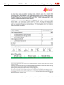
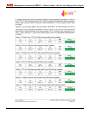
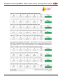
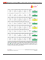
SIL-Safety Instructions SM/TTX200/TTX300/SIL-EN Temperature Transmitter TTH200, TTR200, TTH300, TTF300, TTF350 Information about functional safety Blinder Text Temperature Transmitter TTH200, TTR200, TTH300, TTF300, TTF350 SIL-Safety Instructions SM/TTX200/TTX300/SIL-EN 02.2011 Rev. A Translation of the original instruction Manufacturer: ABB Automation Products GmbH Borsigstraße 2 63755 Alzenau Germany Tel.: +49 551 905-534 Fax: +49 551 905-555 Customer service center Phone: +49 180 5 222 580 Fax: +49 621 381 931-29031 [email protected] © Copyright 2011 by ABB Automation Products GmbH Subject to changes without notice This document is protected by copyright. It assists the user in safe and efficient operation of the device. The contents of this document, whether whole or in part, may not be copied or reproduced without prior approval by the copyright holder. Contents 2 TTH200, TTR200, TTH300, TTF300, TTF350 SM/TTX200/TTX300/SIL-EN Contents 1 2 3 4 5 6 6.1 6.2 7 8 9 10 11 Field of Application ......................................................................................................................................4 Acronyms and abbreviations ......................................................................................................................4 Relevant standards ......................................................................................................................................7 Other applicable documents and papers...................................................................................................7 Terms and definitions ..................................................................................................................................8 Safety function .............................................................................................................................................9 Measuring point for SIL 2 – Single configuration .........................................................................................10 Measuring point for SIL 3 – Dual configuration ............................................................................................11 Periodic checks ..........................................................................................................................................12 Configuration..............................................................................................................................................13 SIL 2 TÜV-Certificate..................................................................................................................................16 Namur NE 93 ...............................................................................................................................................16 Management summary FMEDA – Failure modes, effects, and diagnostic analysis ...........................17 SM/TTX200/TTX300/SIL-EN TTH200, TTR200, TTH300, TTF300, TTF350 3 Field of Application 1 Field of Application Temperature monitoring of solids, fluids and gases of all types in containers and pipes according to the special safety engineering requirements of IEC 61508. The operating limits are defined in the data sheets and operating instructions for the separate models. In case of questions, please contact your ABB partner. 2 4 Acronyms and abbreviations Acronym/ Abbreviation English Description HFT Hardware Fault Tolerance Hardware error tolerance of the unit. Ability of a functional unit (hardware) to continue to perform a required function when faults or errors are prevailing. MTBF Mean Time Between Failures Mean Time Between Failures MTTR Mean Time To Repair Mean time between the occurrence of an error in a unit or system and its repair. PFD Probability of Failure on Demand Probability of hazardous failures for a safety function on demand PFDAVG Average Probability of Failure on Demand Average probability of hazardous failures for a safety function on demand λD Dangerous Rate of hazardous failures (per hour) affecting a channel of a subsystem, corresponds to 0.5 λ (assuming 50% hazardous failures and 50% non-hazardous failures) λDD Dangerous Detected Rate of detected hazardous failures (per hour) affecting a channel of a subsystem. (This is the total rate of hazardous failures within one channel of a subsystem.) λDU Dangerous Undetected Rate of undetected hazardous failures (per hour) affecting a channel of a subsystem. (This is the total rate of undetected hazardous failures within a subsystem.) λSD Safe Detected Rate of detected non-hazardous failures (per hour) affecting a channel of a subsystem. (This is the total rate of detected non-hazardous failures within one channel of a subsystem.) λSU Safe Undetected Rate of undetected non-hazardous failures (per hour) affecting a channel of a subsystem. (This is the total rate of undetected non-hazardous failures within one channel of a subsystem.) TTH200, TTR200, TTH300, TTF300, TTF350 SM/TTX200/TTX300/SIL-EN Acronyms and abbreviations Acronym/ Abbreviation English Description SIL Safety Integrity Level The international standard IEC 61508 defines four discrete Safety Integrity Levels (SIL 1 to SIL 4). Each level corresponds to a range of probability for the failure of a safety function. The higher the Safety Integrity Level of the safety-related systems, the lower the probability that they will not perform the required safety function. SFF Safe Failure Fraction Proportion of non-hazardous failures; in other words, the proportion of failures without the potential to put the safety-related system in a hazardous or impermissible state. Low Demand Mode Low Demand Mode of operation Measurement type with low request rate. Measurement type for which the request rate for the safety-related system is not more than once a year and not greater than twice the frequency of the retest. DCS Distributed Control System Control system used in industrial applications to monitor and control decentralized units. HMI Human Machine Interface In this case, the HMI is a combined module consisting of an LCD display with or without a local keyboard. DTM Device Type Manager A DTM is a software module that supports specific functions for accessing device parameters, the setup and the operation of devices, and diagnostics. The DTM is not executable software. It requires an FDT container program in order to be activated. LRV Lower Range Value Lower measuring range limit URV Upper Range Value Upper measuring range limit Multidrop Multidrop-Modus In multidrop mode, up to 15 field devices are connected in parallel to a single wire pair. The analog current signal simply serves to supply power to the devices in two-wire technology with a fixed current of ≤ 4 mA. SM/TTX200/TTX300/SIL-EN TTH200, TTR200, TTH300, TTF300, TTF350 5 Acronyms and abbreviations Acronym/ Abbreviation 6 English Description closed coupled Short connecting lead to the temperature sensor, less than 1 m (39.37 inches) in length and connecting lead laid with mechanical protection. extension wire Long connecting lead to the temperature sensor, more than 1 m (39.37 inches) in length or connecting lead laid without mechanical protection. low stress Low to medium load according to data sheet specification (sensor exposed to temperature and mechanical load) high stress High load according to data sheet specification (sensor exposed to temperature and mechanical load) Single Configuration Single configuration, i.e. use of one transmitter per measuring point. This results in an HFT = 0 (1oo1 architecture) for corresponding SIL2. Dual Configuration Dual configuration, i.e. use of two transmitters per measuring point. In this configuration the two current signals 4 … 20 mA have to be evaluated accordingly by the downstream logics unit (a DCS, for example). This results in an HFT = 1 (1oo2 architecture) for corresponding SIL3. TTH200, TTR200, TTH300, TTF300, TTF350 SM/TTX200/TTX300/SIL-EN Relevant standards 3 4 Relevant standards Standard Designation IEC 61508, Part 1 to 7 Functional safety of electrical/electronic/programmable electronic safety-related systems Other applicable documents and papers Please comply with the following documents in addition to observing the SIL safety instructions: Product designation Document name Document type TTH200 DS/TTH200 Data sheet TTH200 OI/TTH200 Operating instructions TTH200 CI/TTH200 Commissioning instructions TTR200 DS/TTR200 Data sheet TTR200 OI/TTR200 Operating instructions TTR200 CI/TTR200 Commissioning instructions TTH300 DS/TTH300 Data sheet TTH300 OI/TTH300 Operating instructions TTH300 CI/TTH300 Commissioning instructions TTF300 DS/TTF300 Data sheet TTF300 OI/TTF300 Operating instructions TTF300 CI/TTF300 Commissioning instructions TTF350 DS/TTF350 Data sheet TTF350 OI/TTF350 Operating instructions TTF350 CI/TTF350 Commissioning instructions The documents can be downloaded in the available languages from the ABB website at "www.abb.com/temperature". In addition, the user of this device is responsible for ensuring compliance with applicable legal regulations and standards. SM/TTX200/TTX300/SIL-EN TTH200, TTR200, TTH300, TTF300, TTF350 7 Terms and definitions 5 8 Terms and definitions Terms Definitions Dangerous failure A failure that has the potential to place the safety-related system in a dangerous state or render the system inoperative. Safety-related system A safety-related system carries out the safety functions that are required to achieve or maintain a safe state, e.g., for a system. Example: A pressure meter, a logics unit (e.g., limit transmitter) and a valve constitute a safety-related system. Safety-related functions A specified function that is carried out by a safety-related system with the goal, under consideration of a defined dangerous incident, of achieving or maintaining a safe state for the system. Example: limit temperature monitoring. TTH200, TTR200, TTH300, TTF300, TTF350 SM/TTX200/TTX300/SIL-EN Safety function 6 Safety function TTH200-.H, TTR200-.H, TTH300-.H, TTF300-.H, and TTF350-.H transmitters generate a linear temperature unit signal of 4 ... 20 mA. All safety functions refer strictly to the analog output signal. The entire valid range for the output signal must be configured between min. 3.8 mA and max. 20.5 mA (factory setting). WARNING! In safety mode, HART communication occurs only when write protection is activated. The HART master must comply with the safety requirements of the customer application. Alarm behavior and current output When a critical error is detected, the configured alarm current is generated and fed to a downstream logics unit (a DCS, for example), which checks for overshoots of a defined maximum value. There are two selectable modes for this alarm current: • HIGH ALARM (high alarm, maximum alarm current); this is the factory setting • LOW ALARM (low alarm, minimum alarm current) The low alarm current can be configured in a range from 3.5 … 4.0 mA. The factory setting is 3.6 mA. The high alarm current can be configured in a range from 20.0 … 23.6 mA. The factory setting is 22 mA. In the following cases, a detected error is displayed independently of the configured alarm current within the low alarm range: • Runtime errors • Memory error (non-volatile data, RAM, ROM) After switching on or restarting the transmitter electronics unit, the minimum low alarm time (LOW alarm, startup time) is 10 to 15 seconds. WARNING! To ensure accurate error monitoring, the following conditions must be fulfilled: • The low alarm must be configured to a value 3.6 mA. • • The high alarm must be configured to a value 21 mA. The DCS must identify the configured high and low alarms as malfunctions, and the alarm must be configured accordingly. WARNING! To ensure reliable functioning of the current output, the terminal voltage at the device must be between 11 V and 42 V DC (non-hazardous-area design) and 11 V and 30 V DC (hazardous area design). SM/TTX200/TTX300/SIL-EN TTH200, TTR200, TTH300, TTF300, TTF350 9 Safety function The DCS power supply for the transmitter must be capable of providing the required voltage level even when the current output is running with the configured high alarm. The device does not meet safety requirements under the following conditions: • During configuration • When write protection is deactivated • When HART multidrop mode is activated • During a simulation • When the safety function is being checked WARNING! The device's safety function includes the basic device TTH200-.H, TTR200-.H, TTH300-.H, TTF300-.H, and TTF350-.H with connected sensor, inclusive of the housing and the process connections used. The information in the corresponding documentation must be taken into consideration. Overall safety accuracy The value defined for the overall accuracy of the safety function for this device is ± 2% of the measuring range. The basic accuracy depends on the sensor model and is specified in the corresponding data sheets. Switch-on time and safety operating mode After switching on the device, all safety-relevant errors are detected after 2 minutes in low demand mode. 6.1 Measuring point for SIL 2 – Single configuration One transmitter DCS for SIL2 E D J A B C A00132 Fig. 1 A Sensor B Transmitter C DCS 10 D 4 ... 20 mA measurement circuit E Interface for LCD indicator TTH200, TTR200, TTH300, TTF300, TTF350 SM/TTX200/TTX300/SIL-EN Safety function 6.2 Measuring point for SIL 3 – Dual configuration Two transmitters DCS for SIL3 E D J A B E H J F G C A00264 Fig. 2 A Sensor 1 B Transmitter 1 C DCS D Measuring circuit 1 E Interface for LCD indicator F Sensor 2 G Transmitter 2 H Measuring circuit 2 Important (Note) The safety-relevant technical parameters are specified in chapter 11 „Management summary FMEDA – Failure modes, effects, and diagnostic analysis“, page 17. SM/TTX200/TTX300/SIL-EN TTH200, TTR200, TTH300, TTF300, TTF350 11 Periodic checks 7 Periodic checks Safety inspections The safety function for the entire safety loop must be checked regularly in accordance with IEC 61508. The inspection intervals are defined when calculating the individual safety loops for a system. Users are responsible for selecting the type of check and the intervals within the specified period. The PFDAV value depends on the selected inspection interval. For the PFDAV values in the SIL declaration of conformity, the inspection interval T[Proof] for checking the safety function is 1 year. For other inspection intervals with corresponding PFDAV values, refer to the section titled "Management summary FMEDA". Inspections must be conducted in a manner that enables users to verify the proper function of the safety equipment in combination with all components. One possible procedure for recurring tests to detect hazardous and unidentified device errors is described in the following section. This test is able to detect 99 % of the "Du" errors affecting the transmitter. Checking the safety function To check the safety function of the device, proceed as follows: 1. Bridge the safety DCS or take other appropriate measures to ensure the alarm is not triggered unintentionally. 2. Deactivate write protection (refer to the relevant operating instructions). 3. Use the EDD / DTM simulation command (Diagnostics / Simulation / Current Output) to set the transmitter's current output to a high alarm value. 4. Check whether the current output signal reaches this value. 5. Use the EDD / DTM simulation command to set the transmitter's current output to a low alarm value. 6. Check whether the current output signal reaches this value. 7. Activate write protection (refer to the relevant operating instructions) and wait at least 20 seconds. 8. Shut down and restart the device. 9. Check the current output with reference temperature; use 2-point calibration for the LRV value (lower measuring range limit 4 mA) and the URV value (upper measuring range limit 20 mA). 10.Remove the bridge from the safety DCS or use another method to restore normal operating conditions. 11.After performing the test, the events must be documented and archived accordingly. An appropriate simulator (Pt100 simulator, reference voltage sources) can also be used to check the transmitter without sensor. The sensor has to be tested in accordance with the SIL requirements of the customer application. SensyTemp TSP temperature sensors can be tested in accordance with the OI/TSP by means of a quick check. 12 TTH200, TTR200, TTH300, TTF300, TTF350 SM/TTX200/TTX300/SIL-EN Configuration K 8 Configuration The device has been configured and tested according to customer order. However, it can be configured via the LCD indicator with a local keyboard or via DTM / EDD through the HART interface. Other configuration tools such as mobile handheld terminals are not described in these instructions. Reliable operation of the device is not assured during configuration. WARNING! Checks: Before commissioning the device, check whether the device setup assures the system's safety function. Make sure that the correct device has been installed at the correct measuring point. Whenever the device is updated (if the device's mounting position is changed or the setup is modified, for example), the safety function of the device must be checked again. Once the safety function has been checked, the device must be write-protected to prevent changes to the setup, since any change to the measurement system or parameters will impair the safety function. To ensure safe operation, the device must be write-protected. To implement this, proceed as follows: Activating / Deactivating write protection 1. TTH300-.H, TTF300-.H, and TTF350-.H via the LCD display with local keyboard Go to "Device Setup", "Write Protection" and enter a password other than "0110" to activate write protection. Enter the password "0110" to disable write protection (see the operating instructions). 2. TTH200-.H, TTR200-.H, TTH300-.H, TTF300-.H, and TTF350-.H via DTM/EDD Go to "Device" and select "Write Protection" to activate the function. If the device is locked (write-protected), it cannot be configured. Write protection is applied for the entire device. Enter the password “0110” to disable write protection. 3. TTR200-.H, TTH300-.H, TTF300-.H, and TTF350-.H, HW write protection via DIP switches Configuration on/off (see the operating instructions) SM/TTX200/TTX300/SIL-EN TTH200, TTR200, TTH300, TTF300, TTF350 13 Configuration WARNING! Checks: Write protection must be checked as follows: 1. TTH300-.H, TTF300-.H, and TTF350-.H locking via the LCD display with local keyboard - Check whether the lock icon is displayed on the LCD display. - Select the "Fault Signaling" menu and make sure the edit icon is not showing on the LCD display. - Press the Edit button and check that there is no response on the LCD display. 2. TTH200-.H, TTR200-.H, TTH300-.H, TTF300-.H, and TTF350-.H protection via DTM / EDD: - LCD display and local keyboard available: Check as described under Point 1. - No LCD display and local keyboard available (checking write protection): Go to <Device>,<Parameterize> Current Output/Damping and change the damping value, for example. Then select "Save Device Data in Device" and check whether the message "Device is write-protected" is displayed. WARNING! The software write protection does not lock again automatically. It remains unlocked until it is specifically reset. Diagnostics setup The device's diagnostics setup meets safety requirements and includes the following error detections: • Sensor board communication error • Sensor board error • Sensor board A/D converter error • Measuring error device temperature • Sensor limit value alarm upper and lower • TTH300-.H, TTF300-.H, and TTF350-.H, sensor error ch. 1. and ch. 2. • Sensor configuration resistance thermometer, R in two-, three-, and four-wire circuit with wire break and short circuit • Sensor configuration thermocouple, mV with wire break • Redundancy mode ch. 1 and ch. 2 with drift monitoring activated 14 TTH200, TTR200, TTH300, TTF300, TTF350 SM/TTX200/TTX300/SIL-EN Configuration Configuration parameters affecting the safety function All configuration parameters that are changed via the LCD display with keyboard, DTM / EDD or HART communication when write protection is disabled affect the safety function of the device. The parameters are described in the operating instructions. The safety function is checked in accordance with the SIL safety instructions. For redundancy mode with drift monitoring, the following parameters must be set in DTM, EDD on the TTH300-.H TTF300-.H, and TTF350-.H: Redundancy mode on the TTH300-.H, TTF300-.H, and TTF350-.H • Pulse output Active • Pulse time 60 s, continuous pulse • Drift value Configured acc. to customer application • Drift duration Maximum 120 s Sensor type freestyle characteristic and Callendar-Van Dusen on the TTH300-.H, TTF300-.H, and TTF350-.H When using these two configurations, it is necessary to check at least 3 reference points to verify the configured characteristic. For complex curves, check more reference points according to complexity. SM/TTX200/TTX300/SIL-EN TTH200, TTR200, TTH300, TTF300, TTF350 15 SIL 2 TÜV-Certificate 9 SIL 2 TÜV-Certificate 10 Namur NE 93 TTH200-.H, TTR200-.H, TTH300-.H, TTF300-.H, requirements according to Namur NE 93. 16 and TTH200, TTR200, TTH300, TTF300, TTF350 TTF350-.H transmitters meet SM/TTX200/TTX300/SIL-EN Management summary FMEDA – Failure modes, effects, and diagnostic analysis 11 Management summary FMEDA – Failure modes, effects, and diagnostic analysis SM/TTX200/TTX300/SIL-EN TTH200, TTR200, TTH300, TTF300, TTF350 17 Management summary FMEDA – Failure modes, effects, and diagnostic analysis 18 TTH200, TTR200, TTH300, TTF300, TTF350 SM/TTX200/TTX300/SIL-EN Management summary FMEDA – Failure modes, effects, and diagnostic analysis SM/TTX200/TTX300/SIL-EN TTH200, TTR200, TTH300, TTF300, TTF350 19 Management summary FMEDA – Failure modes, effects, and diagnostic analysis 20 TTH200, TTR200, TTH300, TTF300, TTF350 SM/TTX200/TTX300/SIL-EN Management summary FMEDA – Failure modes, effects, and diagnostic analysis SM/TTX200/TTX300/SIL-EN TTH200, TTR200, TTH300, TTF300, TTF350 21 Management summary FMEDA – Failure modes, effects, and diagnostic analysis 22 TTH200, TTR200, TTH300, TTF300, TTF350 SM/TTX200/TTX300/SIL-EN The Company’s policy is one of continuous product improvement and the right is reserved to modify the information contained herein without notice. www.abb.com/temperature Printed in the Fed. Rep. of Germany (02.2011) © ABB 2011 3KXT200005R4801 ABB Limited Salterbeck Trading Estate Workington, Cumbria CA14 5DS UK Tel: +44 (0)1946 830 611 Fax: +44 (0)1946 832 661 ABB Inc. 125 E. County Line Road Warminster, PA 18974 USA Tel: +1 215 674 6000 Fax: +1 215 674 7183 ABB Automation Products GmbH Schillerstr. 72 32425 Minden Germany Tel: +49 551 905-534 Fax: +49 551 905-555 SM/TTX200/TTX300/SIL-EN Rev. A ABB has Sales & Customer Support expertise in over 100 countries worldwide.