1
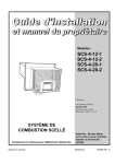
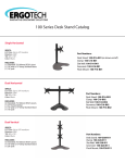
OPERATIONS MANUAL
& PARTS LIST
SC12
Fastracts Extractor
IPC Eagle • 3650 Dodd Rd, Eagan MN 55123 • 800.486.2775 • www.ipceagle.com
BEFORE OPERATING THE MACHINE
Read the manual carefully and completely before attempting to operate the unit. This manual has
important information for the use and safe operation of the machine. Keep this manual handy at all
times. This machine will ensure years of satisfactory service if operated and maintained according to
recommendations in the manual. If additional information is needed, please contact your local
distributor or write to:
IPC Eagle
3650 Dodd Rd
Eagan, MN 55123
All information and specifications printed in the manual and parts list are current at the time of
printing; however, because of Eagle Power’s policy of continual product improvement, we reserve
the right to make changes at any time without notice.
This machine is shipped with antifreeze in the solution line system to protect the pump and valves
from freezing during transport and storage. Before you use the unit, rinse the solution line system
with clean water (See Preparing The Machine).
WARNING
• The machine was designed for use on carpet and upholstery extraction applications as per
instructions and recommendations written in this manual. Any deviation from its proper use or
purpose and the consequential damage that may occur is the sole responsibility of the end
user.
• Disconnect the power cord from outlet before servicing. Do not leave machine connected to
an electrical outlet when unattended.
• Do not immerse or use this machine in standing water. Such use may cause electric shock.
• This equipment is not designed to handle or use combustible/volatile substance such as
gasoline or kerosene, in, on, or near the machine. The use of such materials will cause an
extreme hazard condition.
• When using an extension cord, use only a 3 conductor grounding cord-12 ga. wire or heavier.
• To avoid electric shock, do not expose the unit to rain-store it indoors only.
•
Do not use the machine for dry vacuuming. This machine is not outfitted with a fine dust filter
and it will damage the vacuum motor(s).
•
I
Use defoamer at all times to prevent damage to the vacuum motor(s).
•
Do not use water in excess of 140°F (62°C).
•
Use only commercially available carpet cleaners and defoamer intended for use with
machines of this type. Do not use dyes, bleaches, ammonia or other additives. The use of
powdered cleaning solution if not diluted properly made result in damage to the pump.
•
Do not expose machine to freezing temperatures.
•
All repairs must be done by an authorized Eagle Power repair station.
•
Do not use replacement parts other than those specified in the parts list.
FAILURE TO COMPLY WITH THE ABOVE WARNING INSTRUCTIONS WILL VOID THE
WARRANTY.
GROUNDING INSTRUCTIONS
The 120 V. A/C and the 220 V. A/C models have been outfitted with the appropriate grounded
connectors. Make sure the machine is connected to a grounded outlet having the same configuration
as the grounded plug. No adapter should be used with this machine. Any modification to the connectors
will void the warranty.
PREPARING THE MACHINE
1. Rinse then fill the recovery pail with clean hot tap water (not to exceed 140°F). When pouring
water, make sure drain hose is clipped in the upright position. Pour the water into the solution
tank.
2. Add recommended amount of cleaning solution to the tank, follow mixing directions on label for
best results.
3. Set the recovery pail back in place. Add recommended amount of defoamer to the recovery
pail. Close the lid.
TO CLEAN CARPET
1. Connect machine to a grounded electrical outlet.
2. Turn on the VACUUM, PUMP and BRUSH switches.
3. Lift up on the handle grips to insure that the front of the machine rests on the carpet. Slowly pull
the machine backwards while pressing on the carpet spray switch (below the left handle grip).
Monitor the extraction process through the vacuum lid. Release the spray switch 6 inches before
ending the stroke.
NOTE:
If dirty solution does not appear through the vacuum lid check to be sure if:
• The vacuum lid is resting properly on the recovery pails
• The machine’s nose is touching the carpet in the working mode.
• The solution tank is not empty.
4. Roll the machine forward on its four wheels for next stroke. Make overlapping passes to prevent
streaking. Check solution level from time to time (see solution indicator tube on rear left corner of
the back).
NOTE: If foam appears on vacuum lid, turn the VACUUM SWITCH OFF IMMEDIATELY. Add more
defoamer to the recovery pails to dissolve foam or empty the recovery pails.
5. When the solution tank runs empty, turn off the vacuum, pump and brush switches. Empty the
recovery pail and rinse thoroughly. Then repeat steps on PREPARING THE MACHINE.
TO ATTACH ACCESSORY HOSE
1. Remove 2" hose adapter connection from machine.
2. Attach 1 1/2" assembly with adapter plate to vacuum lid inlet.
3. Pull back female quick disconnect sleeve on the machine and insert male plug on the solution
hose.
Attach 1-1/2" assembly
Remove 2" hose adapter
TO EMPTY THE SOLUTION TANK
1. Unhook the drain nozzle (located on the side of the machine from the drain clips), placing the
end of the hose into the recovery pail.
AFTER EACH USE
• Empty and thoroughly rinse the recovery pail.
• Coil power cord onto the cord wrap.
• Remove dirt and lint build-up inside vacuum lid filter screen.
• Clean solution line filter.
• Wash the vacuum lid with a soap solution and sponge to prevent dirt from accumulating on
the surface. (To avoid scratching use soft cloth only).
• Lean the machine back on its 4 wheels during storage or when it’s not in use to prevent
brush distortion.)
MAINTENANCE
The upright extractor is engineered for minimum maintenance. But it does require some care to keep it in
optimum working condition. Careful attention to these maintenance instructions will give you maximum
operating performance and life expectancy of the machine.
•
Solution line, fittings and accessory tools. -Flush the machine and accessories at least once a
month with solution of 1 part water to 3 parts white vinegar to neutralize the alkaline residue left by
the cleaning solution.
•
Filter Solution screen. -Unscrew bowl and rinse screen in running tap water. If screen is clogged up
with soap, soak in vinegar solution and brush clean.
•
Vacuum lid screens. -Always keep the screen clean in order to maintain maximum suction and
airflow performance from the vacuum motor. The screens also prevent lint from accumulating in the
vacuum motor fan chamber thus increasing the productive life of the motor. Do not operate the unit
without the screen installed! If the screen gets lost or damaged, replace it immediately.
•
Quick disconnect coupler. -Spray with lubricant (WD-40) or equivalent to prevent coupler from
sticking.
TROUBLESHOOTING
ELECTRICAL SYSTEM
PROBLEM
POSSIBLE CAUSE
No electrical power.
1. Defective power cord.
2. House or building circuit breaker trips.
Switch is turned on.
Power is imtermittent to motor.
1. Faulty electrical cable.
2. Defective Switches.
3. Loose terminal or discolored terminal connections.
VACUUM SYSTEM
PROBLEM
POSSIBLE CAUSE
No Vacuum
1. Vacuum lid is not resting on recovery pail.
2. Loose vacuum hose, vacuum connection.
Low Vacuum
1. Accumulated dirt on lid screen.
2. Worn out vacuum lid gasket.
3. Lint & dirt build-up on suction head. (brush chamber).
4. Defective vacuum hose.
5. Loose connection in the vacuum motor.
SOLUTION SYSTEM
PROBLEM
Pump motor on, no
spray thru carpet
spray tips or
accessory tool
POSSIBLE CAUSE
1. Clogged spray tips.
2. Clogged solution intake filter screen.
3. Clogged solenoid valve or open solenoid coil.
4. If carpet spray works normally, plugged up female quick
disconnect coupler.
5. Punctured pump diaphragm
6. Defective pump check valve.
7. Crack in pump housing.
8. Debris in check valve.
Uneven or weak spray
from tips.
1.
2.
3.
4.
5.
6.
Carpet spray is
turned off solution
still drips from
spray tips.
1. Debris caught in between the 3 solenoid valve parts
andthe plunger.
Vacuum motor working
pump motor fails to
turn on.
1. Loose “Molex” plug connector. Loose wiring connection.
2. Defective pressure switch in pump motor (100 psi model).
3. Defective pump motor or rectifier.
Clogged or dirty spray tips.
Accumulated dirt on solution intake filter screen.
Accumulation of debris inside pump and plumbing.
Worn pump bearing (excessive noise).
Punctured pump diaphragm.
Defective rectified
ROTARY BRUSH SYSTEM
PROBLEM
Motor runs, brush
won’t spin.
Brush motor fails
to turn on after
circuit breaker has
been reset.
POSSIBLE CAUSE
1. Loose pulley tension.
2. String caught between walls.
1. Defective bridge rectifier.
2. Defective motor.
Floating brush won’t
move up and down.
1. Debris caught inside the slide block guide.
BRUSH DRIVE BELT SERVICE AND/OR REPLACEMENT (refer to parts diagram).
1. Remove 2 1/4-20 hex screws attaching lower frame to upper frame.
2. Remove (2) spring cover plate assemblies and carefully remove springs from the slide blocks.
3. Loosen (2) 1/4-20 hex screws that hold brush motor bracket in place. Push bracket toward the front of
the machine to loosen belt.
4. Remove right Open-End and left Pulley-End cover plates.
5. Slide brush assembly and slide blocks out from their guides. Replace worn and defective belt.
6. Reinstall above components. Clean accumulated lint or debris
inside the slide block guides and check for wear on the teflon
surfaces. Replace if necessary. The slide block washer (item
#36) must be installed between the slide block guide and inside
the divider wall. Adjust belt tension by moving motor bracket
toward the rear. Apply minimum belt tension when the hex
bolts are tightened to allow for a smooth vertical brush
movement. A belt too loose will cause the belt to skip when
brush is applied on the carpet. A belt too tight won’t allow for
up and down movement.
36
REPLACEMENT OF BRUSH ASSEMBLY AND/OR BEARINGS
1. Repeat steps 1 thru 4.
2. Remove slide blocks from the ends of the brush shaft.
3. Remove (4) screws from string guard. Tap the shaft toward the right open end to remove the bearing.
4. Remove (4) screws from slinger and pull off brush core. Scrape off old sealant build up on the slinger and
string guard. It is advisable to replace the two bearings every time the brush is replaced.
5. Reinstall the above component. CAUTION! Install shorter step on the shaft ends toward the left pulley
side. Apply silicon sealant such as GE Silicon auto seal onto the ends of the brush core before
reassembling the slinger and string guard.
Fastracts SC12
Fastracts SC12
Fig. 2
Fastracts SC12
Fig. 5
Fastracts SC12
Fig. 6
PARTS LIST
FASTRACTS SC7 and SC12
Item
Description
Part No.
Qty.
Fig.
1
2
CLIP, ADAPTER RETAINER
HOSE, ADAPTOR
D02391
D02359
1
1
1
1
3
4
SEAL, VACUUM INTAKE
SHAFT, LID PIVOT
E02431
D02373-1
1
2
1
1
5
SPRING, DOME PIVOT
SPRING, SLIDE BLOCK
D02372
D02372
1
4
1
2
6
7
VACUUM LID ASSEMBLY
GASKET, VACUUM LID
80491-1A
E03431
1
1
1
1
8
9
FILTER SCREEN ASSEMBLY, VACUUM LID
HOSE, VACUUM, 2" ID
82407A
J00618
1
2
1
1
10
11
PLUG, SOLUTION TANK
RECOVERY PAIL
L00767
F02465-7
1
1
1
1
12
RECOVERY PAIL
DRAIN NOZZLE, 1/2 BARB x 1/2 BARB
F02465-6
A00165
1
1
1
1
13
14
CLIP ASSEMBLY, DRAIN HOSE
HOSE, DRAIN, 5/8 OD x 1/8 WALL
80263-3A
J00598
2
1
1
1
15
16
90 ELBOW, 1/2 MP x 3/8 BARB
90 ELBOW, 1/2 MP x 5/8 BARB
A00138
A00099
1
1
1
1
17
18
CLAMP, HOSE, 5/8
CLAMP, HOSE, 7/8
J00637
J00652
2
1
1
1
19
21
HOSE, SOLUTION, 3/8 ID
DECAL KIT
J00613
H02561
1
1
1
1
22
DECAL KIT
SOLUTION TANK ASSEMBLY
H02552
F02463-12
1
1
1
1
23
24
SOLUTION TANK MOUNTING KIT
HOUSING, MOTOR, PLASTIC
82310A
F02470-G
1
1
1
1
26
27
BRUSH DRIVE MOTOR ASSEMBLY (220V)
82538-1A
WIRE ASSEMBLY, GROUND (VACUUM MOTOR) 00185-6A
1
1
2
2
28
29
PULLEY, BRUSH DRIVE MOTOR
BELT, TIMING
D00398-A
L00779-1
1
1
2
2
30
COVER PLATE ASSEMBLY, SPRING
82378A
1
2
PARTS LIST
FASTRACTS SC7 and SC12
Item
Description
Part No.
Qty
Fig.
31
BRUSH CHAMBER ASSEMBLY
82362A
1
2
32
33
90 ELBOW, 1/8 FP x 1/4 C
GLIDE, BACK, SS
A00144
D02366
2
1
2
2
34
35
GLIDE, FRONT, SS
SLIDE BLOCK ASSEMBLY
D02365
80500A
1
2
2
2
36
37
WASHER, SLIDE BLOCK, 1/16 THK, 25/64 ID, 2" OD F00504
STRING GUARD ASSEMBLY
82235A
1
1
2
2
38
39
BEARING, BRUSH
BRUSH
G00536
F00505
2
1
2
2
40
41
SHAFT, BRUSH STEEL 1/2” x 18”
SLINGER ASSEMBLY, ROTARY BRUSH
D02371
82376A
1
1
2
2
42
43
PULLEY, ROTARY BRUSH
WASHER, 3/32 THK, 7/16 ID, 5/8 OD (14")
D00398-2
C02298
1
4
2
2
44
45
SPRAY TIP , Brass 1/8” NPT
COVER PLATE ASSEMBLY, OPEN END
A00091-1
82368A
1
1
46
47
COVER PLATE ASSEMBLY, PULLEY END
LABEL KIT, ENGLISH
82367A
1
1
2
1,5,6
48
PIVOT, LID FRAME EXTENSION, STEEL
1” SQUARE TUBE
D02344-1
D02344
2
2
5
49
50
BRACKET ASSEMBLY, HOSE GUIDE
PIN ASSEMBLY, RETAINING
82361A
82383A
1
1
5
5
51
52
CLAMP ASSEMBLY, CORD
CAP, END
80187A
K00712-4
1
4
5
5
53
54
GASKET, COOLING AIR DUCT
HOSE, EXHAUST, 1” ID X 7”
E02450
J00654
2
1
5
5
55
56
DUCT, COOLING AIR, STEEL
FRAME, UPPER, STEEL
D02343
D02342-1
1
1
5
5
57
58
FOOT, RUBBER
WHEEL ASSEMBLY
K00705
82514A
2
1
5
5
59
60
BUSHING
AXLE, WHEEL
K00674
D00418-14
2
1
5
5
61
62
MUFFLER ASSEMBLY
CLIPS, MUFFLER, STEEL
80790A
D02380
1
2
5
5
2
2
PARTS LIST
FASTRACTS SC7 and SC12
Item
63
Description
VACUUM MOTOR MOUNTING ASSEMBLY (2 STAGE)
Part No.
82291A
Qty.
1
Fig
5
64
65
LOOM, CORRUGATED, 26”
VACUUM MOTOR, 2 STAGE, 5.7” DIA, 115V
F00463
00537A
1
2
5
5
66
W/MOLEX CONNECTOR
CAP, LATCH HANDLE
K00725
1
5
67
68
LATCH HANDLE ASSEMBLY
CAPSCREW, MACHINE STEEL HEX HEAD
82355A
C02310
1
1
5
5
69
1/4-20 X 1-1/4” LG
LATCH HANDLE SPRING ASSEMBLY
82357A
1
5
70
71
TEE, MALE BRANCH, BRASS, 1/8 MP x 1/4 C
90 ELBOW, 1/8 MP x 1/4 C
A00143
A00132
1
1
5
5
72
73
SOLENOID, 1/8 NPT (115V)
BRANCH TEE, MALE 1/8 NPT
G02536
A00135
1
1
5
5
74
75
NIPPLE, SHORT, 1/8 NPT
BUSHING, REDUCER, 3/8 NPT (50 PSI)
A00055
A00168-1
1
1
5
5
76
BUSHING, REDUCER, 1/4 NPT (100 PSI)
90 ELBOW, 1/4 MP x 1/4 C (100 PSI)
A00168-18
A00140
1
1
5
5
77
78
TUBE FITTING, BRASS 1/4”X1/4” C
NUT, HEX
A00145
A00124
1
2
5
5
80
81
SHAFT ASSEMBLY, HANDLE
TUBE, COPPER, 1/4” OD, LEFT TIPS
80418-6A
A00085-5
1
1
5
2
82
83
TUBE, COPPER, 1/4” OD, RIGHT TIPS
TUBE, COPPER, 1/4” OD X 25 7/8” LG
A00085-4
A00085-7
1
1
2
2
84
85
TUBE, COPPER, 1/4” OD X 16-9/16” LG
SPACER, 3/16 THK, 1/2 ID, 1" OD
A00085-6
C00240
1
5
2
2
86
87
GASKET, VACUUM MOTOR
BRACKET, BRUSH DRIVE MOTOR
E02448
D02370
1
1
5
2
88
PUMP MOTOR, INTERNAL BYPASS,
1240VAC, W/MOLEX CONNECTOR (100 PSI)
02513F-100A 1
5
89
90
LOWER FRAME ASSEMBLY
ADAPTER, 3/8 BARB x 1/4 FP
02341A
A00061
1
1
5
5
91
92
90 ELBOW, 1/4 FP x 1/4 MP
FILTER STRAINER, IN-LINE
A00052
K00709
2
1
5
5
93
94
QUICK DISCONNECT, 1/4 FP x 1/4 FP
SWITCH GUARD ASSEMBLY
A00102
82414A
1
1
5
6
95
96
COVER, ROCKER SWITCH
SWITCH, LIGHTED, ROCKER
B00214-2
B02211-1
3
3
6
6
PARTS LIST
FASTRACTS SC7 and SC12
Item
Description
Part No.
Qty.
Fig.
97
98
LIGHT, INDICATOR, GREEN LENS
GRIP, HANDLE, BLACK
B021916
K00715B-1
1
2
6
6
99
BOOT, FLEX, CIRCUIT BREAKER
(115v - 1REQ.)
B02193
1
6
100
101
SPRING, BRACKET, VACUUM VALVE, ASSEMBLY
SPRING, VACUUM VALVE SLIDE RETURN
102
103
HANDLE, ADJUSTABLE
SHAFT, VACUUM VALVE
D02403
D03356
1
1
6
104
105
CIRCUIT BREAKER, 3 A
OUTLET ASSY, ACCESSORY (OPTIONAL)
B02192
80188A
1
1
6
6
106
107
CORD WRAP ASSEMBLY
CORD ASSEMBLY, HANDLE TO LOWER FRAME
82408A
00185-32A
1
1
6
6
108
109
GASKET, HANDLE
COVER PLATE ASSEMBLY
E03432
82409A
1
1
6
6
110
111
LOCK NUT (115VAC)
CORD, POWER (115VAC)
B00201
B00221-2
1
1
6
6
112
113
SWITCH, 10 AMP, 250 FAC
STRAIN RELIEF, POWER CORD (115VAC)
B02213
1
1
6
7
120
HARNESS, RECTIFIER
00185-29A
1
2
121
RECTIFIER, FISH PAPER ASSEMBLY
B02171
1
2
163
RECTIFIER
M00843
1
2
1
2
Fastracts SC12
Warranty Policy
Limited Warranty
Eagle Power Products (EPP) warrants new cleaning equipment against defects in material and
workmanship under normal use and service to the original purchaser as detailed below.
10 Years
Subject to the conditions stated below, EPP warrants polyethylene tanks and housings to be
free from defects in materials and workmanship for a period of ten years.
3 Years
Subject to the conditions stated below, EPP warrants all automatic scrubber components to
be free from defects in materials and workmanship for a 3-year period. Parts replaced or
repaired are warranted for the remainder of the original warranty period.
1 Year
Subject to the conditions stated below, EPP warrants all other cleaning equipment
components to be free from defects in materials and workmanship for a 1-year period. Parts
replaced or repaired are warranted for the remainder of the original warranty period.
Batteries are prorated for one year.
EPP will furnish and charge for replacement parts, including transportation, to the original
owner through an EPP authorized service center. If the part is returned within 30 days and is
found defective, the owner will be credited for the cost of the replacement part including
shipping and handling.
Labor charges are covered for one year from the date of purchase if provided by an authorized
EPP service center. Travel is covered for 90 days for battery operated equipment only.
Wear items exempt from warranty include belts, carbon brushes, power cords, wheels, pad
drivers, clutch plates, brushes, pads, handle grips, filters, screens, throttle cables, and squeegees.
This warranty shall not apply to failures caused by misuse or abuse, improper
maintenance as stated in the operation manuals, use of unauthorized repair parts, repairs
by other than an EPP authorized service center, and damage in transit.
EPP disclaims and denies any liability for any direct, indirect, special incidental or consequential damage
which may be suffered as a result of sale, delivery, servicing, use, loss of any product, downtime, labor,
freight, or other charges not expressly included herein.
Date Purchased:
Model Number:
Serial Number:
Please be sure to record this information. This information will be necessary for future warranty claims.
IPC Eagle Products Sales and Service Provided by:
3650 Dodd Rd, Eagan MN 551213
800-486-2775, 651-686-5399
www.ipceage.com