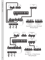
1
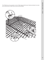
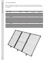
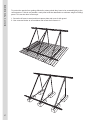
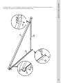
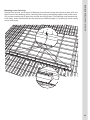
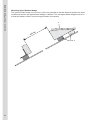
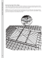
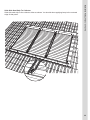
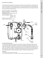
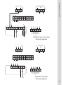
Instruction Manual
Issue 4
Note: These Instructions Should Be Read Carefully Before
Install, And Before Calling Technical Support.
Contents
Table Of Contents:
Introduction - Page 2
Health & Safety Information - Page 2
Post Installation - Page 2
Section 1 - Product Specifications S Class 10 Specification S Class 20 Specification S Class 20 Pro Specification - Page 3
- Page 3
- Page 4
- Page 5
Section 2 - Positioning & Piping Positioning The Panels Piping Schematics For Panels - Page 6
- Page 6
- Page 7
Section 3 - On Roof Frames Sharks Fin Frame Slate Bolt Frame A Frame Installation - Page 8
- Page 10
- Page 18
- Page 25
Section 4 - In Roof Frames S Class 20 In Roof Installation S Class 10 In Roof Installation - Page 34
- Page 34
- Page 52
Section 5 - Connections & Components - Page 77
System Piping- Page 77
Insulation- Page 77
Glycol- Page 77
Double Pump Station
- Page 78
Expansion Vessel- Page 79
Section 6 - Filling The System
- Page 80
Filling The System- Page 80
Section 7 - Controller Setup
Setting Up The SHE-02
Setting Up The Solastat
Setting Up The Resol (East/West Split)
Setting Up The Resol (2 Store System)
- Page 81
- Page 82
- Page 82
- Page 83
- Page 83
Section 8 - Commissioning & Maintenance
Commissioning Certificate
Product Guarantees
Maintenance
- Page 84
- Page 84
- Page 85
- Page 85
Section 9 - Service Log
- Page 86
Service Log- Page 86
1
This installation manual contains essential information for the effective and safe installation of RM
Solar products. It is essential that this kit is fitted by someone with relevant training or previous
experience in the field of Solar Thermal, if this kit is installed without prior training or qualification
your guaranteed may be void and your help limited.
This technical documentation should be available with you at all times during the installation, but
prior to installation please read these instructions as in many cases it will prevent problems from
occurring during the installation process.
Health & Safety Information
RM Solar panels are high quality thermal solar panels using selective coating technology to convert
light into heat. RM Solar panels should only be fitted by authorised, trained and qualified personnel.
They are not intended to be a “do it yourself” product. Panels are also sometimes called “solar
collectors”.
Introduction, Health & Safety, & Post Installation
Introduction
When fitting the panels installers shall comply with all relevant health and safety regulations and
shall carry out a suitable and sufficient risk assessment before any work commences.
Pre Installation
•
•
Please ensure all equipment is on site, and no parts are damaged.
Please make a note of any solar panel serial numbers.
Post Installation
After the correct and full installation and commissioning of the RM Solar system please make sure
you take the following steps:
In The Manual Please:
•
•
Complete the product guarantee form included with the solar kit.
Complete the product commissioning certificate.
Ensure that you:
•
•
•
Explain how the system works and how to get the best from the system to the customer.
Make sure these instructions are left with the customer.
Service the system in accordance with recommended guidance, and complete the log as
appropriate.
2
Section 1 - Product Specifications
S Class 10 Specification
RM Solar’s new S Class 10 panel comes in a variety of arrangements, including standard vertical,
oversized vertical, and horizontal panels.
Technical Information
Collector Casing:
Material: Colour: Back Plate: Aluminium Profile
Brown
AlZn 0.5mm
Transparent Cover:
Type: Standards: Dimensions: Young Factor: Poisson Factor: Expansion Factor: Light Transmittance: Glass Sealing: Temperated Glass, 4mm
prEN 12150, BS6206 Class A
1000 x 2000 / 1200 x 2000
E=70Gpa
μ=0.22
0.000009m/mok
>89% +/-0.5%
Silicone
Insulation:
Type:
Rockwool With Black Fleece
Thickness:40mm (back)
20mm (side)
Density:40kgr/m3
Thermal Conductivity:
0.044W/mK (100oC)
S Class 10
S Class 10 Horizontal
S Class 10 Pro
Overall Area (m )
2.09
2.09
2.49
Absorber Area (m2)
1.92
1.92
2.31
2
Aperture Area (m )
1.92
1.92
2.31
Length (mm)
2030
1030
2030
Width (mm)
1030
2030
1230
Height (mm)
87
87
87
2
Overall Weight (kg)
Collectors Installation
49.60
50.50
Horizontal
Vertical
Absorber Type
Grid
Grid
Grid
Absorber Capacity (l)
1.97
1.97
2.23
Selective
Selective
Selective
Coating
Thickness (mm)
0.50
0.50
0.50
Absorption
95% +/-2%
95% +/-2%
95% +/-2%
Emission
5% +/-2%
5% +/-2%
5% +/-2%
Laser
Laser
Laser
Welding Process
Stagnation Temperature
Certifications
Max Working Pressure (Bar)
191
191
193
Keymark
Keymark
Keymark
10
10
10
Glycol
Glycol
Glycol
S Class 10
S Class 10 Horizontal
S Class 10 Pro
78.6
75.9
74.5
a1 (W/m K)
3.62
3.038
3.556
a2 (W/m2k2)
0.028
0.042
0.017
Heat Transfer Medium
Type
Efficiency (%)
2
3
48.20
Vertical
RM Solar S Class 20 solar panel is a vertically mounted glazed collector with collection
pipes, intended for applications in systems equipped with circulating pumps.
The RM Solar S Class 20 panel is constructed with a single meander system piping without using
soldering or welding and is folded into the absorber plate; a single piece tray folded into the frame
holding the glazing.
The RM Solar S Class 20 panel is not intended to be used in drain-back systems.
Section 1 - Product Specifications
S Class 20 Specification
Technical Information
• Floor Space : 2.03 m2
• Dimensions : 1010 x 2010 mm
• Weight empty : 36.5 kg
• Fluid Volume : 1.3 litres
• Recommended flow of heat transfer fluid : 30 L/h/m2 collector
• Stagnation temperature : 170°C
• Panel connection : in series
• Maximum number of panels that can be linked in a series : 3
• Maximum number of series : 1
• Maximum number of panels in parallel: 10 - Please see page 20.
• Glazing : 4mm low iron hailstone resistant
Tested to EN 12975 (parts 1 & 2) and to Solar Rating & Certification Corporation Standards for the
United States of America and to all applicable Canadian test standards
Maintenance
The panels have been designed to withstand high temperatures; the glass does not require cleaning.
There are no user serviceable parts inside and due to the heat exchange process the panel does not
contact potable water or water to be heated.
Important
The panels must be covered for a minimum of 1 hour before filling the system with glycol.
4
Section 1 - Product Specifications
S Class 20 Pro Specification
The RM Solar S-Class Pro Panel has been specifically designed to meet the needs of large
industrial applications. Suitable for both Commercial Buildings, and Private applications, such as
large swimming pool installations.
The S-Class Pro panels are also available as a horizontal variant allowing installation on roofs where
space is a premium.
The RM Solar S-Class Pro panel is not intended to be used in drain-back systems.
Technical Information
• Floor Space : 2.03 m2
• Dimensions : 1010 x 2010 mm
• Weight empty : 36.5 kg
• Fluid Volume : 1.3 litres
• Recommended flow of heat transfer fluid : 30 L/h/m2 collector
• Stagnation temperature : 170°C
• Panel connection : in parallel
• Maximum number of panels that can be linked : 10
• Maximum number of series : Infinite
• Glazing : 4mm low iron hailstone resistant
Tested to EN 12975 (parts 1 & 2) and to Solar Rating & Certification Corporation Standards for the
United States of America and to all applicable Canadian test standards
Maintenance
The panels have been designed to withstand high temperatures; the glass does not require cleaning.
There are no user serviceable parts inside and due to the heat exchange process the panel does not
contact potable water or water to be heated.
Important
The panels must be covered for a minimum of 1 hour before filling the system with glycol.
5
South Facing Roofs
Positioning the collectors is important for optimum performance. Collectors should ideally be
mounting at an angle of between 30 degrees and 60 degrees on a south facing position that is not
shaded by overhanging trees, buildings, or structures. Good results can be obtained by positioning
the panels facing anywhere in an arc between south west and south east but due south facing provides optimum performance.
North Facing Roofs
It is not generally recommended that you install the panels on North facing roofs in the Northern
Hemisphere. South of the equator, north will provide the optimum performance and south facing the
worst performance.
Section 2 - Panel Positioning
Positioning the Panels
East / West Facing Roofs
Good results can be obtained by splitting the collector array on East / West elevations but this should
only be used when it is not possible to have a mainly southernly position for the collectors. If you are
installing an East / West split system you have to double the number of panels that would normally
be required, e.g. a 2 panel system would require 2 panels on the east and 2 panels on the west.
East / West Facing Roofs (Alternate Configuration)
Another option is to oversize the collector area on the side of the roof chosen to mount the collectors. E.g. If 2 panels would have been adequate had the roof orientation been south, then 3 collectors would be required on either the east side or the west side depending on which recieved the most
sunlight.
6
Section 2 - Piping Configurations
Piping Schematics For Panels
Typical S Class 10 (Parallel) (Maximum 10 Panels Per Bank)
Airvent
Stop End
Sensor Cable
Stop End
In
Out
Typical S Class 20 (Series) (Maximum 3 Panels Per Bank) (Maximum 10m Primary Circuit)
Sensor Cable
In
Out
Typical S Class 20 (Parallel) (Maximum 10 Panels Per Bank)
Sensor Cable
In
Out
Typical S Class Pro (Parallel) (Maximum 10 Panels Per Bank)
Sensor Cable
In
7
Out
The on roof frames from RM Solar come in the following two styles, choosing the correct frame for
your installation is paramount to an effective install.
Sharks Fin
Primarily suited to tile installs. For installation of this frame please see page 10
Section 3 - On Roof Frames
On Roof Frames
Slate Bolt
Primarily suited to slate installs, but will fit most roof types. For installation of this frame please see
page 18
Note: It is important to note that the S Class 10 Panel is bigger than the S Class 20 product, so
when using on roof products remember to select the correct hole when locating the ‘Z’ rails.
8
Section 3 - On Roof Frames
Roof Space Required
This is the roof space approximately required to install the panels on roof in millimeters.
8320
9360
9
10400
Before attempting to fit your equipment on the roof please ensure that you have all the equipment
required to complete the installation. The table below will tell you what pieces are included in each of
the packages.
Part
Name
1 Panel
1 Panel
Extension
2 Panel
Frame
Connector
-
1
Steel Pipe = 2000mm
-
-
2
2
Steel Pipe = 1000mm
2
2
-
-
3
Connection Bolt
-
-
-
2
4
Pipe Bracket
4
4
6
-
5
Shark Tail
4
2
4
-
6
U-Bolt Bracket M8
4
2
4
-
7
Washer M8
8
4
8
-
8
Nut M8
8
4
8
-
9
Adjustment Screw M8
5
2
5
-
10
L-Rail
2
1
2
-
11
Z-Rail Long - 2080mm
-
-
2
-
12
Z-Rail Short - 1040mm
2
2
-
-
13
Frame Connector
-
-
-
2
14
Wind Clamp
2
2
4
-
15
Screw M6 x 16
17
9
17
4
16
Wood Screw
14
8
14
-
Section 3 - Sharks Fin Installation
On Roof Sharks Fin
10
Section 3 - Sharks Fin Installation
11
1
11
10
17
1
4
14
15
13
15
The instructions show the installation of a 3 panel kit, be sure to only make the connections, and
holes in the roof that you require.
11
Section 3 - Sharks Fin Installation
Exploded View
3 Panel On Roof Tile Frame
(Comprising 2 Panel Frame and 1 Extension)
9
12
8
7
6
10
2
3
12
15
10
5
3
2
12
Section 3 - Sharks Fin Installation
Search for the rafters at the position of the collector field. Push up or remove tiles on the total length
of the collector field.
ca.
104
0m
m
m
0m
80
17
98
-1
ca.1
040
m
m
Using the wood screws provided mount the support pipe using the pipe brackets. The distance
between the lower batten and pipe centre should be 90mm. If more panels are added use the
extension bolts to join the pipes. Extensions must be mounted with 2 pipe brackets [4]. The end
brackets should not be more than 500mm from the end of the support pipe.
m
90 m
1
2
1
max 500mm
3
1
2
17
4
13
2
9
8
50
0m
7
m
Section 3 - Sharks Fin Installation
Screw the align screw [9] in the centre hole of the shark bracket. Now use the U-Bolt Bracket [6],
washer [7], and nut [8] to fix the hooks to the pipes. Choose so that the brackets are placed under
the centre of the panel. Note: The outside Sharks fin should not be more than 500mm from the
outer panel edge.
Ma
x
9
6
Warning: In areas of heavy snow: please replace roof tile with a metal tile, otherwise the roof
tile might break under heavy snow loads, or use the slate screw installation kit.
14
Section 3 - Sharks Fin Installation
Use screw kit M6 x 16 [15] to connect L-Rails [10] to the Sharks Fin. The end with the most predrilled
holes goes to the top of the roof frame.
15
10
5
10
10
15
5
15
A
B
Section 3 - Sharks Fin Installation
Screw the Z-Rail [11] [12] to the L-Rail [10] using two screws M6 and two washers [16] on each
connection. Maximum Distance from sharks fin to the end of the Z-Rail must not be more than
500mm! If more than 2 panels are to be mounted use the frame connector as shown in fig. C. Before
screws are tightened be sure that a cross measurement has been made. A = B.
15
15
16
16
max. 500 mm
11
12
A
11
B
12
11
12
C
13
15
16
Section 3 - Sharks Fin Installation
Place the panels in the correct position. In case of systems with more than two panels, mount
the panels starting in the middle. Do not forget to secure the panels together with any straight
connectors required (supplied in panel extension set) Mount the wind clamps [14] and connect the
panels.
Design of the wind clamps may vary - this will not effect the performance of the roof frame.
15
14
14
15
17
Before attempting to fit your equipment on the roof please ensure that you have all the equipment
required to complete the installation. The table below will tell you what pieces are included in each of
the packages.
Part
Name
1 Panel
1 Panel
Extension
2 Panel
Frame
Connector
1
Slate Bolt
4
2
4
-
2
L-Rail
2
1
2
-
3
Z-Rail Long - 2080mm
-
-
2
-
4
Z-Rail Short - 1040mm
2
2
-
-
5
Frame Connector
-
-
-
2
6
Wind Clamp
2
2
4
-
7
Screw M6 x 16
13
7
25
-
Section 3 - Slate Bolt Installation
On Roof Slate Bolt
M10 Bolt
2 x M10 Washers
M10 Spacer Nut
M10 Nut
Seal Cap
Weather Seal (Sponge)
Stainless Bolt
18
Section 3 - Slate Bolt Installation
3
7
8
3
2
6
7
7
5
The instructions show the installation of a 3 panel kit, be sure to only make the connections, and
holes in the roof that you require.
19
Section 3 - Slate Bolt Installation
Exploded View
3 Panel On Roof Tile Frame
(Comprising 2 Panel Frame and 1 Extension)
5
4
1
2
4
20
Section 3 - Slate Bolt Installation
Locate the rafters under the slates. Mark the slates where the holes should be drilled so that the
hole penetrates the centre of a rafter. Use the angle rail as a template. Note: The distance from the
slate bolt to the end of the Z-Rail should not be more than 500mm on each side.
ca.
70
-8
00
(*7
00
17
21
)
m
m
0
87
-1
104
0m
m
ca.
m
m
104
0m
m
Section 3 - Slate Bolt Installation
Drill the holes on each marked position with a high quality 25mm masonry bit. Make sure the drill
does not spin too fast or you may break the tile / slate. Do not penetrate beyond the tile / slate. After
drilling the holes into the slates, use an 8mm wood bit to make a hole through the rafters at each
position. Bolt the bottom part of the slate bolt into each hole. Note: The angle between rafter and
drill bit must be 90o.
90°
22
Section 3 - Slate Bolt Installation
Use the bolt kit M10 to connect the L-Rails to the self sealing bolt fitting. Note: The L-Rails must be
mounted into the long adjustable slot.
2
2
1.3
m
23
to
1.8
Ma
x
7
8
Section 3 - Slate Bolt Installation
The Z-Rails have to be screwed on to the L-Rails using the M6 screws. Maximum distance from slate
bolt to the end of the Z-Rail must not be more than 500mm
max. 500 mm
3
4
A
3
7
B
8
4
3
4
5
7
24
Section 3 - A Frame Installation
25
A Frame Installation
Before attempting to fit your equipment on the roof please ensure that you have all the equipment
required to complete the installation. The table below will tell you what pieces are included in each of
the packages.
Part
Name
1 Panel
2 Panel
Frame
Connector
1 Panel
Horizontsl
1
Rail A
1
2
-
2
2
Rail B
1
2
-
2
3
Rail C
1
2
-
2
4
Z-Rail Long
-
2
-
2
5
Z-Rail Short
1
-
-
-
6
Frame Connector
-
-
2
-
7
Rail D
-
1
-
1
8
Wind Clamp
2
4
4
4
9
Screw M6x16
10
19
-
19
10
Washer 8,4
5
9
-
9
11
Washer 6,4
-
2
-
2
12
Screw M8 x 20
-
2
-
-
13
Nut M8
-
2
-
-
Section 3 - A Frame Installation
Exploded View
3 Panel On Roof Tile Frame
(Comprising 2 Panel Frame and 1 Extension)
9
8
4
9
10
10
9
13
7
6
4
12
7
6
1
5
3
2
9
5
26
Section 3 - A Frame Installation
27
To protect the panels from getting affected by strong winds they have to be screwed tightly to the
rood structure. If this is not possible, each panel must be attached to a minimum weight of 220kg/
panel. This can be done in two ways:
1. Screw the A frame to an aluminium trapeze plate and cover it with gravel.
2. Use concrete blocks as a foundation and screw the A frame to it.
1
2
Section 3 - A Frame Installation
Screw the rails 1, 2, and 3 together using 6mm screws (9). The bottom rail has holes for ground or
roof fixing. The holes for wall fixing have to be drilled on site.
9
1
2
2
3
9
3
9
1
3
28
Section 3 - A Frame Installation
Mount the Z profile, the distance between the last triangle and the end of the Z rail must not be more
than 500mm. Pay attention that the triangles are aligned to each other. Use a string to check this,
the Z rails must be mounted without any tension. Check cross measurements (A=B). Mount frame
connectors if required.
10
9
max 500 mm
5
4
A
4
B
9
5
10
9
29
6
13
Section 3 - A Frame Installation
Drill holes 8.5mm on the appropriate place of the back rails. Use the cross rail (D) as a template.
Attach cross rail (D), using screws (12), washers (10) and nuts (13), to the back rail of the frame.
10
12
7
13
10
12
7
30
Section 3 - A Frame Installation
Mount the panels starting in the middle, mount the wind clamp (8) using screw (9) to the top and
bottom of the panel. 4 Wind clamps must be used per horizontal panel.
9
8
8
9
31
8
Section 3 - A Frame Installation
Proceed with the next panel. Place extension kit on connection before you place the panel. Make the
panel connections.
9
32
Section 3 - Slate Bolt Installation
Place the panels in the correct position. In case of systems with more than two panels, mount
the panels starting in the middle. Do not forget to secure the panels together with any straight
connectors required (supplied in panel extension set) Mount the wind clamps [14] and connect the
panels.
Design of the wind clamps may vary - this will not effect the performance of the roof frame.
15
14
14
15
33
The In roof frames from RM Solar come in the following two styles, choosing the correct frame for
your installation is paramount to an effective install. Minimum roof pitch for installation is 28o
Tile In Roof
The tile in roof has a shallower profile to accommodate the panels with the thicker roof covering, a
flexible corrugated lead flashing is also present to allow moulding to a rolling tile.
Section 4 - In Roof Frame Installation
In Roof Frames - S Class 20
Slate In Roof
The slate in roof has a deeper profile to accommodate the panels with the thinner roof covering.
Currently the S Class 20 Panel can only be installed In Roof up to 3 panels, and cannot be installed
using the “parallel” method.
34
2540m m
3580m m
4620m m
2550 m m
Section 4 - In Roof Frame Installation
Preparation
The following is the area space required by a set of in roof panels, please ensure you have this area
available to you before attempting installation of your equipment.
5660m m
2550 m m
5660m m
2550 m m
6700m m
2550 m m
7740m m
2550 m m
8780m m
Note: Additional materials and tools necessary and not included in the equipment supplied:
35
•
Minimum of 3 battens in the same size as the ones used in the roof, it can be possible to use
battens from the area under where the collector will be mounted.
•
Wood Screws 4 x 80 to fix the battens to the roof.
•
Battery drill with 2.5mm HSS drill bit, hammer, measuring tape, wood saw, grinder with stone
blade, plumbers tools, ladder, and rope with lashings.
25
20
23
26
23
1
12
Section 4 - In Roof Frame Installation
22
23
3
8
22
2
7
9
10
24
8
4
25
21
23
15 23
10
16
26
23
11
2
8
7
8
9
24
25
5
20
23
10
17
15 23
26
11
23
8
2
8
7
9
6
24
23
8
23
18
10
15 23
8
26
13
25
21
14
22
19
22
20
36
Section 4 - In Roof Frame Installation
37
Important
When unpacking the in-roof frame package please check if any pieces are missing using the list
below. The pack should contain the following pieces:
No.
1
2
3
4/5
6
7/14
8
9
10
11
12/13
15
16
17/18
19
20
21
22
23
24
25
26
Item
Angle Bracket
Lower Wooden Slat
Bottom L/H Flashing
Bottom Center Flashing
Bottom R/H Flashing
Seal Strip 20x20
High Load Support Brackets
Wood Wedge
Side Seal Strip
Center Flashing
Side Flashing
Wind Protection Rail
Top L/H Flashing
Top Center Flashing
Top R/H Flashing
Nail Strips
Triangular Seal
Sealed Screws (4.5x35)
Wood Screws (4x30)
Wood Screws (5x110)
Sealed Screws (4x80)
Wood Block with Hole
Single Frame
2
1
1
N/A
1
2.8m
4
1
4m
N/A
2
1
1
N/A
1
10
1.8m
4
36
3
2
2
Extension
2
1
N/A
1
N/A
2.2m
2
1
4m
1
N/A
1
N/A
1
N/A
2
1.2m
N/A
15
3
2
1
Attach the lower support batten, screw the lower support batten to the rafter along where the
collectors are going to be placed. Use screws (4.5x80)
Note: These battens and screws are not included.
A
Section 4 - In Roof Frame Installation
Installation
Remove the tiles / slates required for installation:
2 Panel Flashing Set = 260 x 260
110cm for every further panel in the same row
A = 8,5 - 12 cm
38
Section 4 - In Roof Frame Installation
Mount Angle Brackets
Mount angle brackets (1) in equal distance with each 4 screws 4x30 (23) to the support batten. With
more than 2 collectors, mount first and last angle bracket. Now use a string to level the rest of the
brackets by stretching it from one to the other. Now place the lower wooden slat (2) with the cut edge
showing upward and screw to angle brackets with each 4 screws 4x30 (23). If the battons are narrow
please use 2 battons to mount the brackets.
B
1
23
39
B = 0,5 cm
2
2
23
1
4
23
5
Section 4 - In Roof Frame Installation
Mounting Lower Flashings
Starting from left side, screw lower left flashing (3) at left end to lower slat (2) with screws 4x30 (23).
Mount rest of lower flashing (4/5/6) continuing left to right, push flashing together and fit with screw
(23) to lower wooden slat (2) where the overlap and on right end. (The flashings must interlock with
each other). When finished stick the seal strip at top of flashing edge (7) (covering the screw heads)
across total length.
3
4
5
7
6
40
Section 4 - In Roof Frame Installation
Mounting Upper Wooden Wedge
The upper wooden wedge (no in set incl.) has to be mounted so that the distance between the lower
wooden slat and the top angled timber wedge is 1950mm. The top angled timber wedge must sit on
at least two battens. Mount a second support batten if necessary.
9
m
c
5
9
5
191
m
0m
mind. 2
41
Section 4 - In Roof Frame Installation
Place and Align Collectors
Distance A = 10cm, Distance B = 10cm
Place 2 high load support brackets (8) under each collector side.
8
A
B
42
Section 4 - In Roof Frame Installation
Mounting Top Angled Timber Wedge
Place top timber wedge (9) under each collector, align them and secure each with 2 screws 5x110
(24). Connect collector connections as shown in the collector installation manual. Make sure to do a
quick A = B measurements on the panels to ensure they are square.
NOTE: Pressure test the panels and insert temperature sensor into R/H panel. The panels should
be pressure tested to 6.5 bar using either compressed air, or glycol, DO NOT USE WATER. If using
glycol cover the panels for the duration of the test.
24
9
A
B
43
Section 4 - In Roof Frame Installation
Stick Side Seal Strip To Collector
Stick side seal strip to the collector sides as shown. You should when applying keep to the external
edge of that panel.
10
10 mm
44
Section 4 - In Roof Frame Installation
Mount Center Flashings
Place center flashing (11) on the lower collector edge and snap in starting from the bottom to the top.
Ensure the flashing snaps in tight, if required adjust the gap on the underside of the flashing. Secure
flashing into wooden block (26) using screws supplied (25).
N.B. Do not over tighten screw (25) this will deform the flashing.
11
25
11
26
45
12 13
Section 4 - In Roof Frame Installation
Mount Side Flashings
Push the side flashing (12/13) from the side over the collector edge. Use sealing screws (25) to fix
the flashings as shown. Be Careful! Do not bend the flashings. The 8” long slit on the side flashings
goes at the bottom of the collectors and allows the flashing to flex onto the roof covering.
12
13
25
22
13
46
Section 4 - In Roof Frame Installation
47
Place Top Seal Strip
Stick top seal strip (14) across the total length.
14
23
Section 4 - In Roof Frame Installation
Wind Protection Rail
Place wind protection rail (15) and fix with wood screws 4x30 (23) each 4 times. Note that the buckle
must be placed direct over the edge of the wooden wedge (9). Each end of the wind protection rail
should overlap the vertical flashings and pin the top of the vertical flashings in place.
15
48
Section 4 - In Roof Frame Installation
Top Flashings
Starting from the left side. Push top corner flashing (16) under the wind protection rail (15), when
located correctly you should no be able to lift the leading edge. Fix with wood screw 5x30 (23) on the
right joint and with sealing screw (22) from the left side. Continue with parts (17/18/19).
16
17
Lead
ing E
dge
23
23
18
22
22
49
NOTE: Seal (21) must be placed at least 10cm down the side flashings (16/19).
Additional seal can be ordered from the outlet where the kit was purchased.
Section 4 - In Roof Frame Installation
Nail Straps
Fix top flashings (16/17/18/19) with 2 nail strips and side flashing (12/13) with 4 nail strips (20) each.
Stick wedge formed seal (21) across the total length. It must be placed so that after replacing the
tiles it will be approximately 5cm under the bottom tile edge.
21
min. 10 cm
20
50
Section 4 - In Roof Frame Installation
51
Place Tiles
If necessary, cut tiles to make them fit. Please use the diagram as a guide as to where to tile up to.
min.
The In roof frames from RM Solar for the S Class 10 Panel only come in one style which is
suitable for all roof coverings regardless of whether they are tile or slate. Minimum roof pitch for
installation is 28o.
This style comes complete with the flexible corrugated lead flashing for molding to a rolling tile.
Section 4 - In Roof Frame Installation
In Roof Frames - S Class 10
52
2615m m
3700m m
4785m m
2610 m m
Section 4 - In Roof Frame Installation
Preparation
The following is the area space required by a set of in roof panels, please ensure you have this area
available to you before attempting installation of your equipment.
5870m m
2610 m m
5870m m
2610 m m
6955m m
2610 m m
8040m m
2610 m m
9125m m
Note: Additional materials and tools necessary and not included in the equipment supplied:
53
•
Minimum of 3 battens in the same size as the ones used in the roof, it can be possible to use
battens from the area under where the collector will be mounted.
•
Wood Screws 4 x 80 to fix the battens to the roof.
•
Battery drill with 2.5mm HSS drill bit, hammer, measuring tape, wood saw, grinder with stone
blade, plumbers tools, ladder, and rope with lashings.
Item
Small Wood Screws (4x30)
Large Wood Screws (5x110)
Sealing Screws (4x80)
Small Self Tapping Screws
Side Seal Strip
Top Square Seal
Triangular Seal
Bottom L/H Flashing
Bottom R/H Flashing
Bottom Centre Flashing
Colour Coded Bottom L/H
Colour Coded Bottom R/H
Colour Coded Bottom Centre
Middle Flashing
L/H Side Flashing
R/H Side Flashing
Top L/H Flashing
Top R/H Flashing
Top Centre Flashing
Wind Retaining Rail
Nail Strips & Nails
Top Wooden Wedge
Wood Side Section
Single Frame
20
10
14
7
4.3m
1.5m
1.8m
1
1
N/A
1
1
N/A
N/A
1
1
1
1
N/A
1
10
1
2
Extension
15
7
7
1
4
1.2
1.2
N/A
N/A
1
N/A
N/A
1
1
N/A
N/A
N/A
N/A
1
1
2
1
1
Section 4 - In Roof Frame Installation
Important
When unpacking the in-roof frame package please check if any pieces are missing using the list
below. The pack should contain the following pieces:
54
Section 4 - In Roof Frame Installation
55
Installation
Remove the tiles / slates required for installation:
2 Panel Flashing Set = 270 x 270
110cm for every further panel in the same row
Section 4 - In Roof Frame Installation
Secure Battens
Attach 2 battens using (4.5x80 - not supplied) 450mm and 350mm from the top of the batten
beneath.
56
Section 4 - In Roof Frame Installation
Mounting The Flashings
Starting from the left hand side, place the left hand apron flashing onto the top batton (450mm) and
screw into position (just use the top screw holes to secure in place at this point).
Note: Please remove the protective plastic coating from the pieces of flashing before it is installed.
57
Section 4 - In Roof Frame Installation
Mounting The Flashings
Connect the right hand apron flashing to the left hand apron flashing as illustrated (below) ensuring
that they interlock correctly.
58
Section 4 - In Roof Frame Installation
59
Mounting The Flashings
Note: If the system is larger than 1 panel then the apron from the extension kit is placed between the
right hand and left hand flashing of the 1 panel flashing frame.
Section 4 - In Roof Frame Installation
Mounting The Flashings
Slide the colour coded flashings over the galvanized section of the apron, start with the middle
sections first (the left hand and right hand corners are always found in the one panel kit box and not
on the extension boxes).
60
Section 4 - In Roof Frame Installation
61
Mounting The Flashings
These pieces also interlock.
Section 4 - In Roof Frame Installation
Mounting The Flashings
When interlocking correctly the colour coded cover flashing will butt up to the galvanized fixing plates
at each end.
62
Section 4 - In Roof Frame Installation
Mounting The Flashings
Now insert the rest of the fixing screws into the galvanized fixing plates. (approx 100mm from the
top).
Place the left hand panel into the galvanised fixing plate so it is positioned as shown (below).
63
Section 4 - In Roof Frame Installation
Mounting The Flashings
Insert the pipe reinforcers (supplied in the install and extension kits) into the panel connections, also
put a capnut and olive on to the connection.
Now put the neighboring panel (if 2 or more panels) in place, insert pipe reinforcers, capnuts and
olives into the panel connections and join the 2 panels together using 2 x 22mm straight connections
supplied.
The panels at both ends of the collector array should be just lapped by the apron flashing at the
bottom when sighted correctly.
64
Section 4 - In Roof Frame Installation
Mounting The Flashings
At this point measure diagonally across the panels. The two measurements should be the same to
ensure the panels are square. A must equal B.
A
B
Mount the wooden latts supplied down the sides (and middle is using 2 or more panels) of the
panels using the 3 x large wood screws supplied (5x110mm). The wooden latts should be positioned
200mm from the bottom of the panels and should screw to the battens with a screw at the top middle
and bottom. The latts require pilot holes to prevent splitting.
The latts are tapered and the 90mm end goes to the top of collector array with the 95mm end going
to the bottom.
65
Section 4 - In Roof Frame Installation
Mounting The Flashings
The panels can now be piped up and the pipework inserted through the roof felt.
The panels should now be pressure tested to 6.5bar using either compressed air or glycol.
Note: If using glycol cover the panels for at least an hour before and at all times during the test.
The picture shown above assumes the panel doesn’t have an in built stat pocket. RM are gradually
introducing them across the range. If your panel doesn’t have a stat pocket please attach as photo
above. If there is a pocket in the panel please insert the probe into this and secure, the above fitting
is then replaced with a T-Piece complete with airvent.
66
Section 4 - In Roof Frame Installation
67
Mounting The Flashings
For every panel there will be 1 x wedge shaped wooden section, this needs to be mounted on 2
battens directly above the panel, and secure in place using 2 x (5x110mm) wood screws.
Section 4 - In Roof Frame Installation
Mounting The Flashings
Stick the weather seal (supplied on a roll) to the colour coded apron flashing at both corners and up
the vertical edges of the panels. (This foam expands to 10mm deep).
68
Section 4 - In Roof Frame Installation
Mounting The Flashings
Mount the left hand side flashings starting with the bottom screw, use 1 x small self tapping seal
screw (4.5x35mm) at the bottom and 6 x larger sealing screws (4x80mm) up the length, ensure the
flashing runs parallel to the panel.
Mount the middle vertical flashing (for 2 or more panels) and the right hand side flashings in the
same manner.
Note: the middle apron flashing will need a 3mm pilot hole drilling on the upstand to enable the small
self tapping seal screws (5x35mm) to be fitted.
69
Section 4 - In Roof Frame Installation
Mounting The Flashings
Stick the square seal along the top of the panels also over the face of the side and middle vertical
flashings.
70
Section 4 - In Roof Frame Installation
71
Mounting The Flashings
Screw the wind retaining rails into place, the angel should run parallel with the edge of the wooden
wedge and should lap over the vertical flashings at either side using small wood screws (4x30).
Leading
Section 4 - In Roof Frame Installation
Mounting The Flashings
Starting at the left hand side mount the top flashing ensuring that the leading edge hooks under
the wind retaining rail. When located correctly you will not be able to lift the leading edge by hand.
Secure in place using 1 x (4x30mm) wood screws (this screw needs to be located as indicated so as
not to compromise the water tightness of the flashings.
Edge
72
Section 4 - In Roof Frame Installation
73
Mounting The Flashings
The top flashings interlock in the same way the apron flashings interlock, continue from left to right.
The clips and galvanized nails are used to secure the side flashings and the top flashings to the
battens.
Section 4 - In Roof Frame Installation
Mounting The Flashings
Stick the triangular seal along the top of the top flashings and down each side by at least 150mm (if
required additional seal is available to order through your merchant from RM Solar).
74
Section 4 - In Roof Frame Installation
75
Mounting The Flashings
A small seal screw (4.5x35mm) is used to secure the four corners of the flashings in place, you may
need a 3mm HSS drill to pilot these holes.
Section 4 - In Roof Frame Installation
Mounting The Flashings
The roof covering can now be installed at least to the ridge on the side flashings and to the angle on
the top flashings.
76
Section 5 - Piping System, Insulation & Glycol
System Piping
Once you have made the connections in accordance with page 7 be sure to seal and pressure test
to at least 1 and a half times the proposed working pressure of the system (suggested working
pressure 3 - 4 Bar), normal testing pressure will be 6.5 Bar. Once the system has been tested
connections can be taken from the roof space to the proposed location of the double pump station.
Be sure to use 22mm Copper Pipe, and Compression fittings. If required using a small amount of
sealing compound on the outside of the olive is suggested in order to give a good seal for glycol.
Important: Plastic pipe should NEVER be used.
Insulation
The use of the correct insulation is critical. Normal central heating insulation will melt and become
brittle at the very high solar generated temperatures in the system. Insulation materials must endure
the highest occurring temperature, which will be more than 170oC near the collector.
When the insulation is to be used outside it must be:
• Resistant to temperatures up to 170oC
• Must have a flexibility in - 30oC conditions
• Resistant to air pollution
• Resistance to UV radiation
• Resistance to pests, such as mice and birds that may eat it
• Insulation should be externally sealed to prevent it carrying moisture.
RM Solar carry a range of suitable insulation in stock that can be purchashed through your plumbers
merchant.
Glycol
The glycol is used as heat exchange fluid with a very low freezing point, already pre-mixed to allow
give a freezing point of -20oC. RM Solar only recommend using the glycol supplied by ourselves and
that comes as part of the kit purchased. RM Solar glycol has the following properties:
•
•
•
•
•
•
Premixed to give protection down to -20oC (Do not dilute further).
Contains anti-corrosion inhibitors for pipe protection
Glycol is a low toxic polypropylene product approved for use in solar systems by all major
countries including the USA & EU
The glycol has a notably more intensive creeping property than water
Glycol is not compatible with Zinc, so pipes with internal zinc galvanising should not be used
As with all chemicals, normal precautions should be taken in handling the glycol to prevent
ingestion and delivery into the water system.
Important
Under no circumstances should any ethylene based glycol be used in solar systems. The material
safety data sheet for the RM Solar glycol is available from RM Solar on request.
77
The double pump station ensures a continuous circulation of the glycol inside the closed solar loop
when useful energy is available in the solar panels. The double pump station recommended by RM
Solar is constructed so as to be unaffected by the operating temperatures of the loop for many years,
however it is always recommended that in order to protect the pump that the cooler glycol returning
to the panel passes through the pump.
Double Pump Station - Technical Data
Maximum working excess pressure: 6 bar
Safety valve: 6 bar
Circulation pump: Solar Circulating Pump
Nominal voltage: AC 230V
Power consumption: Speed 1 - 45w
Speed 2 - 65w
Speed 3 - 90w
Maximum pump head: 6m
Maximum pump capacity: 6Ltr/Min
Temp.
Gauge 2
Temp.
Gauge 1
Pressure
Relief Valve
Pump
Section 5 - Double Pump Station
Double Pump Station
Expansion
Hose
(Do Not
Insulate)
Pressure
Gauge
Filling Point 2
Expansion
Vessel
Connection
Vessel
Bracket
Filling Point 1
Flow Gauge
Location Of Double Pump
The double pump station must always be mounted at a level that is lower than the panels so that
no steam may penetrate the expansion vessel in case of stagnation. Stagnation occurs when the
solar panels have heat energy which is not needed by the system and the panels stagnate at around
180oC. If the expansion vessel is mounted at the same level or at a higher level than the panels, an
anti-gravity loop must be installed. To install an anti gravity loop the pipe work from the double pump
to the expansion vessel should be hard piped in 22mm copper pipe, the pipe should be allowed to
fall for approximately 1m from the pump, before rising 1m to enter the expansion vessel.
Important
1. Never flush the solar system with water.
2. The double pump station is not suitable for direct contact with swimming pool water.
78
Section 5 - Expansion Vessel
Expansion Vessel
The expansion vessel protects the solar system during pressure changes and temperature
fluctuations. For example, in very hot conditions when energy is not being drawn off, the system may
overheat causing the glycol to expand.
Technical information (Standard 18L Vessel):
Maximum pressure: 10 bar
Working pressure: 3.0 - 4.0 bar (20oC)
Gas pressure: 2.5 bar
Maximum working temperature: 130oC
Membrane: Nytril (butyl) rubber
Resistance: 40% glycol
Sizing
It is of critical importance to have the correct size of expansion vessel in your solar system. The
volume of the expansion vessel is determined by the number of RM Solar solar panels connected
within the one solar heating system. Approximately for one collector 6 litres of expansion vessel
volume is required. When fitting a system larger than 3 panels RM Solar should be consulted on
expansion vessel sizing.
Location
The pressure vessel should be located in a position where it can be easily accessed. It should be
fitted with isolating valve for ease of replacement. The isolating valve should not be accessible
without a tool so that an unqualified person cannot shut it off. The expansion vessel should be fitted
on the return run of the system.
Where the expansion vessel is sited at the same level as the panels or above, a thermal loop should
be present.
Maintenance
Once an expansion vessel is pressurised correctly it will require yearly maintenance and a visual
inspection by a qualified person. Monthly checking of the pressure gauge on a double pump station
is also very important, as well as pressure testing the expansion vessel at each maintenance
inspection. A pressure drop might indicate:
•
•
•
A leak on the pipes connections or
A leak on the panels connections or
A faulty expansion vessel or loss of pressure in the expansion vessel
In the case of any unexpected changes, the customer must contact the installer immediately and the
installer should inform the customer of this when explaining the system.
Important
When installing your expansion vessel ensure that you have not mixed the expansion vessel with
another one from somewhere else. The solar expansion vessel has been carefully designed to work
with glycol without corrosion. The solar expansion vessel should be clearly marked as being a solar
expansion vessel.
79
This guide assumes the use of an RM Solar Filling Pump, no other methods are supported by RM
Solar as they can often lead to excess air in the system.
Prior To Filling The System
Cover the panels 30 minutes before filling the system, and leave covered whilst filling. (If it is not
possible to cover the panels, fill the system when there is little solar energy, e.g. early morning, late
evening.
Ensure the expansion vessel pressure has been set correctly at 2.5 bar.
Section 6 - Filling The System
Filling The System
Connecting The Filling Pump
At the Pump Station:
1. Connect the right hand hose (Side with the pressure gauge) of the pumping station to the top
filling pump connection of the filling pump.
2. Connect the left hand hose of the filling pump to the bottom filling connection on the solar
pumping station.
3. Twist the red and blue temperature gauges on the solar pump station 45o clockwise.
4. Close the grub screw (twist all the way in) on the solar pump station, this is between the pump
and the flow gauge.
5. Open the butterfly valves on the pump station where the filling pump hoses are connected,
manually open any zone valves ect on the solar primary pipe work.
At the Filling Pump:
1. Open the right hand isolation valve, close the left hand isolation valve and open the isolation
valve beneath the white tank.
2. Fill the white tank at least half full.
Running The Filling Pump
1. Switch on the filling pump - keep the tank topped up to half full.
2. The pressure can be adjusted using the fill pressure regulator on the filling pump.
Whilst Filling:
1. Whilst filling open the bleed screw on the solar circulating pump, expel all the air and then reclose.
2. Allow the filling pump to circulate for approximately 1 hour.
3. Check in the filling tank that no air bubbles are returning with the glycol.
4. Close the isolating valve on the solar pump station beneath the circulating pump.
5. Allow the system to pressurise to between 3-4 bar.
6. Close the isolation valve beneath the pressure gauge beneath the pressure gauge on the solar
pump station.
7. Switch off the filling pump and close the isolation valves.
8. Remove and drain the hoses from the solar pump station.
80
Section 7 - Controller Setup
81
Control Setup
RM Solar provide the original instruction book from the manufacturer for each of the solar controllers
supplied, however provided are the recommended wiring details for the controllers most scenarios
available. Please check carefully to see which diagrams apply to the controllers being used.
The Stelflow hot water cylinder as supplied by RM Solar is designed to work perfectly in conjunction
with any RM Solar controller we supply, when using hot water cylinders other than those supplied by
RM Solar a pipestat/control stat may be required to enable the solar controller to function correctly.
L
N
E
6
Energy Cut
Out
1
C
2
4
1
2
3
4
5
6
7
8
9 10
1
2
3
4
5
6
7
8
9 10
L
N
E
COM
T2 AL AL P1
N
E
6
2
2
3
L
N
E
5
3
Br Bl G O Gy
2 Port Valve
(Fitted Below Pump)
(If not required link 6 & 5
together)
SHE-02 Solar Controller
Wiring Diagram
3
5
1
6
Energy Cut
Out
1
C
4
2
3
4
5
6
7
8
9 10
1
2
3
4
5
6
7
8
9 10
L
N
E
+
-
+
2
3
4
L N
E
P
Roof Cyl
6
Solar Controller
1
1
2
1
5
2
E
Stat
L T1
Solar Pump 1
N
3
4
Solar Controller
1
E
Section 7 - Controller Setup
3
Stat
Solar Pump 1
5
3
3
Br Bl G O Gy
2 Port Valve
(Fitted Below Pump)
(If not required link 6 & 5
together)
Solastat Controller
Wiring Diagram
82
L
N
Energy Cut
Out
E
1
C
1
2
3
4
5
6
7
8
9 10
1
2
3
4
5
6
7
8
9 10
L
N
E
4
2
6
4
S1
3
S3
4
5
L
6
1
5
3
9
3
L
N
E
1
C
N
E
5
6
7
8
9 10
1
2
3
4
5
6
7
8
9 10
L
N
E
2
6
3
1
C
2
E
3
1
6
Solar Controller
5
E
Energy Cut
Out
7
4
S3
4
(If not required link 6 & 7
together)
L
4
Tank Sensor 2
3
Tank Sensor 1
Panel Sensor 1
2
3
2 Port Valve
(Fitted Below Pump 2)
Energy Cut
Out
3
12 13 14 15 16 17 18 19 20
1
7
2 Port Valve
(Fitted Below Pump 1)
6
2
S2
1
Br Bl G O Gy
3 Port Valve
10 15 3
1
10
S1
2
Br Bl G O Gy
4
3
6
Resol BS Plus - East / West Split
Wiring Diagram
Solar Pump 1
Tank Sensor 1
2
(If not required link 4 & 5
together)
Panel Sensor 2
2
Panel Sensor 1
1
S2
N
Solar Controller
12 13 14 15 16 17 18 19 20
E
E
1
3
83
2
Stat
E
3
Stat
Store 1
N
5
Stat
Store 2
L
3
Solar Pump 1
Solar Pump 2
Section 7 - Controller Setup
7
2
Store 1
1 7
3
2
Store 2
1
9
3
Br Bl G O Gy
Br Bl G O Gy
2 Port Valve
(Fitted Below Pump)
2 Port Valve
(If not required link 6 & 7
together)
Resol BS Plus - 2 Store Priority
Wiring Diagram
The following steps are important when ensuring the system has been installed correctly and has
been setup to run correctly under normal operating circumstances.
1. Ensure the red and blue valves on the solar pumping station are twisted as far anti clockwise as
possible (usually inline with the pipework).
2. Open the grub screw beneath the circulating pump fully by turning anti clockwise as far as
possible.
3. Set the circulating pump on speed 1, power up the RM Solar Controller and adjust the settings if
required. Never run the solar pump dry, doing so will invalidate any pump guarantees.
4. Put the RM Controller into manual operation (ensure any motorised valves ect. on the solar
primary pipework have opened).
Section 8 - Commissioning & Maintenance
Commissioning
5. Set the flow rate between 0.5-1L/m per panel, e.g. a 2 panel system requires a flowrate of
between 1-2L/m.
6. To slow the flowrate slowly close the grub screw beneath the solar pump by twisting clockwise.
7. To increase the flowrate switch the circulating pump speed setting up at the pump.
8. When the desired flow rate has been achieved put the controller into automatic mode.
The system has now been correctly commissioned.
84
Section 8 - Commissioning & Maintenance
Product Guarantee
RM Solar Products are guaranteed by RM Solar Ltd as follows:
Thermal Solar Panels (Performance) - S Class 20 Only
Thermal Solar Panels (Manufacture & Corrosion) - S Class 20 Only
Thermal Solar Panels (Manufacture & Corrosion) - S Class 10 Only
Pump Station, Controller & Heat Exchanger
Other RM Solar Products
20 Years
20 Years
10 Years
1 Years
1 Years
In all cases from the day the system was installed & commissioned.
The Guarantee is conditional upon:
• The solar system is installed by an approved RM Solar installer in accordance with recommended
RM Solar techniques & practices, and is serviced in line with our recommendations, and a full
service history is recorded.
• The installation is paid for in full.
• Customer completing the registration form available at the RM Solar website within 28 days of
installation.
• RM Solar being notified of any circumstance giving rise to a claim hereunder within 28 days of
such circumstance arising.
The Guarantee DOES NOT cover:
• Hot water cylinders and thermal stores, which are separately guaranteed by their own
manufacturers.
• Workmanship which is separately guaranteed by the installer.
All statutory rights are not effected by this guarantee and every subsequent owner of the property at
which the thermal solar installation is installed will be recognised hereunder RM Solar Ltd.
Maintenance
These requirements are recommended by RM Solar Ltd and must be adhered to and must be logged
in the service records. Any failure to do so will nullify any manufacturers guarantees, and possibly
installer guarantees. In addition these requirements are separate from any regime for the prevention
of legionella.
The following checks should be carried out at least once every 12 months:
• Visual inspection for weeps, leaks, and fluid escapes
• Manually operate all valves and pumps to ensure they are working correctly
• Visual inspection that system pressure has not dropped into the red zone
• Visual inspection that flow gauges indicate correct flow levels
• Visual inspection that there is no damage to panels or fixings, this can be done from ground level
• If there is pre heating used, regular checks of the heating system for the final heated cylinder
should be made
• Check the pre-charge of the expansion vessel(s)
• Check the whole system for signs of corrosion
• Test glycol with approved testing kit
• Visual inspection that all insulation is in good condition and not becoming brittle or cracked
• If vacuum panels are used, check that the vacuum guage shows that there is still sufficient
vacuum, the pointer should be in the green zone.
Storage vessels should be checked in accordance with manufacturers recommendations.
85
SERVICE 1
DATE:
SERVICE 2
ENGINEER NAME:
ENGINEER NAME:
COMPANY NAME:
COMPANY NAME:
TEL NO.
TEL NO.
COMMENTS:
COMMENTS:
SIGNATURE:
SIGNATURE:
SERVICE 3
DATE:
SERVICE 4
ENGINEER NAME:
ENGINEER NAME:
COMPANY NAME:
COMPANY NAME:
TEL NO.
TEL NO.
COMMENTS:
COMMENTS:
SIGNATURE:
SIGNATURE:
SERVICE 5
DATE:
SERVICE 6
ENGINEER NAME:
ENGINEER NAME:
COMPANY NAME:
COMPANY NAME:
TEL NO.
TEL NO.
COMMENTS:
COMMENTS:
SIGNATURE:
SIGNATURE:
SERVICE 7
DATE:
SERVICE 8
ENGINEER NAME:
ENGINEER NAME:
COMPANY NAME:
COMPANY NAME:
TEL NO.
TEL NO.
COMMENTS:
COMMENTS:
SIGNATURE:
SIGNATURE:
SERVICE 9
DATE:
SERVICE 10
ENGINEER NAME:
ENGINEER NAME:
COMPANY NAME:
COMPANY NAME:
TEL NO.
TEL NO.
COMMENTS:
COMMENTS:
SIGNATURE:
SIGNATURE:
SERVICE 11
DATE:
SERVICE 12
ENGINEER NAME:
ENGINEER NAME:
COMPANY NAME:
COMPANY NAME:
TEL NO.
TEL NO.
COMMENTS:
COMMENTS:
SIGNATURE:
SIGNATURE:
DATE:
Section 9 - Service Record
Service Record
DATE:
DATE:
DATE:
DATE:
DATE:
86