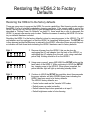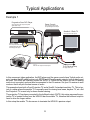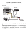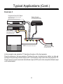
1
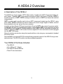
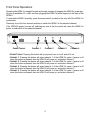
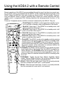
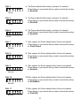
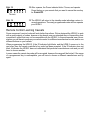
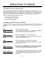
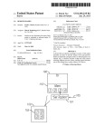
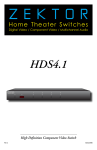
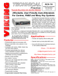
ZEKTOR
TM
HDS4.2
Component Video / Audio Switch
Owner’s Manual
www.zektor.com
Rev: 4
03/11/04
Important Safety Instructions!
Read all instructions for prior to installation of your product.
Retain this User's Manual for future reference.
Adhere to all safety and operation instructions.
Before cleaning this product, unplug from the wall outlet. Do not use liquid cleaning products. Use
a damp cloth for cleaning.
Do not use this product on an unstable cart, stand, or table. The product may fall, causing serious
injury to a child, and serious damage to the product. Ensure that any attached cables cannot be
tripped over.
This product is supplied with a UL Class 2 power supply as indicated on the product packaging. Use
this product only with the supplied power supply. If you are unsure about the type of AC power in
your home, consult your product dealer or a local power company.
Power cords should be routed so they will not be stepped on or rolled over.
If your product is not operating properly, do not attempt to service this product yourself. Refer to a
qualified service personnel.
2
A HDS4.2 Overview
A Description of the HDS4.2
The HDS4.2 is a 4 input, Audio / HDTV Video switch. It supplies two HDTV Component Video outputs. Output 1 (labelled: OUT1) is a passive non-buffered output, and Output 2 (labelled: OUT2) is
a buffered version of OUT1. OUT2 is always a buffered version of OUT1 and cannot be switched
independently.
OUT1 is passive and is usually used to drive a HDTV component located near the HDS4.2, using
short cables. OUT2 is buffered and can be used to drive much longer lengths of cables, such as
those needed to drive an, across the room, projector.
Included are three 75 ohm, RCA jack, terminators. Since the OUT1 is the output of a passive switch,
it relies upon the HDTV to terminate the signals. In cases where OUT1 is not used, such as using
only OUT2 to drive a projector, located across the room, OUT1 must be terminated for proper operations. Whenever OUT1 is left unused, the three supplied 75 ohm terminators must be plugged
into the OUT1 RCA jacks.
Channel selection can be done using front panel switches, or by using any, user supplied, standard
IR remote control.
Also available is an optional RS-232 module allowing extended control of the HDS4.2 using a standard serial port. The RS-232 module must be purchased separately.
Your HDS4.2 Purchase Includes:
•
•
•
•
The HDS4.2.
A 9v, 500ma A.C. Adapter.
The HDS4.2 Owners Manual.
Three 75 ohm terminators.
3
Front Panel Operations
Operating the HDS4.2 is straight forward and simply a matter of plugging the HDS4.2’s power supply into an available A.C. outlet, and then plugging the HDS4.2’s power supply into the back of the
HDS4.2.
To operate the HDS4.2 manually, press the power switch, located on the very left of the HDS4.2 to
cycle power.
Press any one of the four channel switches to switch the HDS4.2 to the selected channel.
If the HDS4.2’s power is turned off, selecting any one of the four inputs will cause the HDS4.2 to
power on and switch to the selected channel.
ZEKTOR
POWER TOGGLE
1
CHANNEL 1
2
3
CHANNEL 2
4
CHANNEL 3
CHANNEL 4
• POWER TOGGLE. Pressing this button will cycle power from on to off, and off to on.
• CHANNEL 1. Pressing this button will select channel 1 of the HDS4.2’s inputs, if power
when this button is pressed, then the HDS4.2 will power on, and select channel 1.
• CHANNEL 2. Pressing this button will select channel 2 of the HDS4.2’s inputs, if power
when this button is pressed, then the HDS4.2 will power on, and select channel 2.
• CHANNEL 3. Pressing this button will select channel 3 of the HDS4.2’s inputs, if power
when this button is pressed, then the HDS4.2 will power on, and select channel 3.
• CHANNEL 4. Pressing this button will select channel 4 of the HDS4.2’s inputs, if power
when this button is pressed, then the HDS4.2 will power on, and select channel 4.
4
is off
is off
is off
is off
Using the HDS4.2 with a Remote Control
Remote operations of the HDS4.2 are accomplished through the use of just about any remote control. A remote control is not supplied with the HDS4.2, yet the versatile programming modes of the
HDS4.2 allows the HDS4.2 to work with virtually any remote control. The next section "Programming your Remote Control" on page 6, describes how to setup your remote controller. After your
remote control is programmed the following describes the pre-programmed functions of the
HDS4.2.
There are 10 separate remote controlled commands understood by the HDS4.2. They are:
POWER
TV
VCR
CBL /
SAT
DVD
RCVR
1
2
3
4
5
6
7
8
9
0
ENT
PIP
VOL
+_
CH
+
_
• POWERTOGGLE.The HDS4.2 can be toggled from standby to power on, and back to standby using a single button of the remote.
• SELECTIN1. Select input 1. If the HDS4.2 is in standby mode, it will
power on and then select input 1.
• SELECTIN2. Select input 2. If the HDS4.2 is in standby mode, it will
power on and then select input 2.
• SELECTIN3. Select input 3. If the HDS4.2 is in standby mode, it will
power on and then select input 3.
• SELECTIN4. Select input 4. If the HDS4.2 is in standby mode, it will
power on and then select input 4.
• POWEROFF. The HDS4.2 can be set to standby mode by pressing
a single button of the remote. Once the HDS4.2 is in standby mode,
further presses of the POWEROFF button will be ignored. This command is useful when using the “macro” feature of some programmable remote controls, and is used when it is unknown whether the
HDS4.2 is already in standby mode or not.
• POWERON. The HDS4.2 can be powered on from standby by pressing a single button of the remote. Once the HDS4.2 is powered on,
further presses of the POWERON button will be ignored. This command is useful when using remote controls that allow “macro” programming, where it is unknown whether the HDS4.2 is already power
on or not.
• SETDIMMODE. Toggles through three different bright/dim display
modes. They are: Bright all the time. Dim all the time. Bright for 4 seconds after any keypress, and then automatically dim.
• SELECT+. Select the next higher input. If input 4 is currently selected,
then this command will cause input 1 to be selected.
• SELECT-. Select the next lower input. If input 1 is currently selected,
then this command will cause input 4 to be selected.
5
Programming your Remote Control
Setting up your Universal Remote Control
For remote control operations, the HDS4.2 requires either a Universal Remote control to be programmed as one of eight pre-programmed devices, or alternatively, the HDS4.2 can be taught to
use most existing remote controls.
The simplest way to begin using the HDS4.2, is to program your Universal Remote control to act
like the remote used to control a Yamaha VCR. Once this is done you will be able to immediately
start using your HDS4.2.
Check your remote’s user manual for instructions on programming your remote control.
The following table shows the Yamaha VCR codes for a few different brands of Universal Remote
Controllers:
Make
Device
Code
Sony
VCR
040
One For All
VCR
0038
Sanyo
VCR
238
GE / RCA
VCR
009
X10
VCR
022
Zenith / Phillips /
Magnavox
VCR
025
6
Using Different Remote Codes
Using Alternate Component Keys on your Remote
The HDS4.2 will also respond to alternate component key codes. Allowing you to use an unused
TV, VCR, RCVR or one of the added AUX positions many remotes include.
Setting up the HDS4.2 to respond to alternate component codes is a two step process. You must
first program your universal remote control to behave as one of the alternate components. You must
then teach the HDS4.2 to respond to the alternate component codes.
Programming your remote to different components
The HDS4.2 will respond to eight different pre-programmed component codes, they are: Yamaha
VCR, Hitachi Satellite, Sony TV, Go Video VCR, Awia DVD, Nakamichi Receiver, Jerrold Cable Box
and a Symphonic TV. The following table shows the different component buttons and codes used
to program a few different universal remotes.
One For
Sanyo RCA
All
Make
Device
Sony
Zenith
X10
Yamaha
VCR
040
0038
238
009
025
022
Symphonic
TV
023
0171
104
189
520
202
Sony
TV
001
0000
110
002
708
015
Hatachi
SAT
N/A
0819
N/A
084
N/A
N/A
Go Video
VCR
N/A
0432
248
138
139
013
Awia
DVD
015
0641
N/A
350
N/A
N/A
Nakamichi
RCVR
086
N/A
N/A
N/A
N/A
N/A
Jerrold
CBL
001
0476
303
046
552
062
If your remote control’s model matches one of the above, read your remote’s user manual for instructions on programming your remote control, then use the above device and manufacturer codes
to setup your remote.
If your remote is not included above list, or the manufacturer code given does not work, then you
will have to follow your remote controls instructions for programming one of the above components
and search for a proper match. See the next section. Or teach the HDS4.2 a new set of codes, See:
"Learning New Remote Codes" on page 9.
Teaching the HDS4.2 a new component code
After your remote control has been programmed to act like one of the 8 built in code-sets, teaching
the HDS4.2 to use the new code set is simple.
7
STEP 1
ZEKTOR
1
2
3
4
1
2
3
4
1
2
3
4
STEP 2
ZEKTOR
STEP 3
ZEKTOR
1 Place the HDS4.2 in standby mode. This is the factory default
mode on power up, and if it has not been changed, you can unplug
the HDS4.2 and plug it back in and it will power up in standby mode
(at this point only the power indicator light is lit and glowing RED).
If the HDS4.2 does not power up in standby mode, follow the steps
given in "Restoring the HDS4.2 to Factory Defaults" on page 14.
2 On your remote control press the buttons in the following
sequence, after each button press verify that the remote IR
indicator flashes. (If you make a mistake, you can start over by
pressing POWER twice.):
• POWER
• CHANNEL +
• POWER
• CHANNEL 3 The HDS4.2 will power up indicating the new component codes
have been accepted.
Searching for a component code in your remote
Assuming you do not have a remote listed in this user manual you will have to follow your remote
control’s programming sequences to find a compatible component that the HDS4.2 understands, or
you can go to the section "Learning New Remote Codes" on page 9, to teach the HDS4.2 new keys
for individual commands.
To search for compatible component codes you must place the HDS4.2 in standby mode and try
manufacturer codes in your remote control until one of them causes the HDS4.2’s IR indicator LED
to flash.
STEP 1
ZEKTOR
1
2
3
4
1
2
3
4
STEP 2
ZEKTOR
1 Place the HDS4.2 in standby mode. This is the factory default
mode on power up, and if it has not been changed, you can unplug
the HDS4.2 and plug it back in and it will power up in standby mode
(at this point only the power indicator light is lit and glowing RED).
If the HDS4.2 does not power up in standby mode, follow the steps
given in "Restoring the HDS4.2 to Factory Defaults" on page 14.
2 Try different manufacturer codes until one of them causes the IR
indicator light on the HDS4.2 to blink when pressing the
POWERTOGGLE key. When found, go to back to "Teaching the
HDS4.2 a new component code" on page 7, to teach the HDS4.2
to use the new component code.
8
Learning New Remote Codes
Teaching the HDS4.2 to use new remote control keys
If your remote does not have one of the pre-programmed component codes, or you simply want to
re-map the HDS4.2 functions to other keys on your remote, the HDS4.2 can be taught to use new
keys.
To teach the HDS4.2 to respond to new keys, you need to have the remote control(s) you want to
use ready, and setup in the manner you want it to be used.
STEP 1
ZEKTOR
1
2
3
4
1
2
3
4
STEP 2
ZEKTOR
1 Place the HDS4.2 in standby mode. This is the factory default
mode on power up, and if it has not been changed, you can unplug
the HDS4.2 and plug it back in and it will power up in standby mode
(at this point only the power indicator light is lit and glowing RED).
If the HDS4.2 does not power up in standby mode, follow the steps
given in "Restoring the HDS4.2 to Factory Defaults" on page 14.
2 Using a pen or pencil, press and HOLD the SETUP button on the
back panel of the HDS4.2 (located near the power jack) for around
4 seconds, until the HDS4.2 powers up, and the Power indicator on
the front panel of the HDS4.2 will turn GREEN and begin to blink
RED.
The HDS4.2 is now ready to accept new remote control key codes. For
each of the following steps:
ZEKTOR
1
2
3
4
1
2
3
4
3 The Power indicator blinks slowly, and input 1 is selected.
STEP 3
ZEKTOR
• You may press a key on your Remote Control, if accepted, the IR
indicator light will blink, and the key will be learned as the new key
for the given function. The HDS4.2 will advance to the next step.
• Or you may press and release the SETUP key on the back panel
of the HDS4.2, this indicates to the HDS4.2 to skip this key, and
the whatever key was previously programmed for that function
will be retained. The HDS4.2 will advance to the next key.
• Or you may press and hold the SETUP key on the back panel until the HDS4.2 returns to standby mode. This will end learn mode,
all keys already programmed will be remembered, and all the
keys skipped will retain their previously programmed values. The
HDS4.2 will advance to Step 13.
Press the key on your remote that you want to use as the new key
for SELECTIN1.
1 BLINK
9
4 The Power indicator blinks slowly, and input 2 is selected.
STEP 4
ZEKTOR
1
2
3
4
2
3
4
1
2
3
4
1
2
3
4
2
3
4
2
3
4
2
3
4
2
3
4
Press the key on your remote that you want to use as the new key
for SELECTIN2.
1 BLINK
5 The Power indicator blinks slowly, and input 3 is selected.
STEP 5
ZEKTOR
1
Press the key on your remote that you want to use as the new key
for SELECTIN3.
1 BLINK
6 The Power indicator blinks slowly, and input 4 is selected.
STEP 6
ZEKTOR
Press the key on your remote that you want to use as the new key
for SELECTIN4.
1 BLINK
7 After a pause, the Power indicator blinks 2 times, and repeats.
STEP 7
ZEKTOR
Press the key on your remote that you want to use as the new key
for POWERTOGGLE.
2 BLINKS
8 After a pause, the Power indicator blinks 3 times, and repeats.
STEP 8
ZEKTOR
1
Press the key on your remote that you want to use as the new key
for SELECTIN-.
3 BLINKS
9 After a pause, the Power indicator blinks 4 times, and repeats.
STEP 9
ZEKTOR
1
Press the key on your remote that you want to use as the new key
for SELECTIN+.
4 BLINKS
10 After a pause, the Power indicator blinks 5 times, and repeats.
STEP 10
ZEKTOR
1
Press the key on your remote that you want to use as the new key
for SETDIMMODE.
5 BLINKS
11 After a pause, the Power indicator blinks 6 times, and repeats.
STEP 11
ZEKTOR
1
Press the key on your remote that you want to use as the new key
for POWERON.
6 BLINKS
10
12 After a pause, the Power indicator blinks 7 times, and repeats.
STEP 12
ZEKTOR
1
2
3
4
2
3
4
Press the key on your remote that you want to use as the new key
for POWEROFF.
7 BLINKS
STEP 13
ZEKTOR
1
13 The HDS4.2 will return to the standby mode indicating a return to
normal operations. The newly programmed codes will now operate
your HDS4.2.
Remote Control Learning Caveats
Some component’s control codes will work better than others. We’ve designed the HDS4.2 to work
with a great majority of codes, however a few brands use non-standard ways of transmitting their
component’s codes that may not be compatible with the HDS4.2. In these somewhat rare circumstances you will have to program your remote control to a different manufacturer’s code, and/or use
different buttons on your remote.
When programming the HDS4.2, if the IR indicator light blinks, and the HDS4.2 moves on to the
next step, then the remote controller’s key code has been accepted. If the IR indicator does not
blink, it indicates the HDS4.2 does not understand that particular manufactures code and you will
have to choose another.
In some cases the remote key code will be accepted, however the range will be limited. If the range
of a programmed key is unacceptable, you will have to choose a different manufacturer and try
again.
11
Bright / Dim / Auto-dimming Modes
Setting the Display intensity modes of the HDS4.2
The front panel display of the HDS4.2 can be set to Bright, Dim or an Auto-dimming mode where
the display brightens for 4 seconds after any function is selected and then auto-dims.
Setting the mode is simply a matter of toggling between the three modes:
• Bright Mode. When pressing the SETDIMMODE key to toggle to this state, the display will turn
bright and remain that way.
• Dim Mode. When pressing the SETDIMMODE key to toggle to the Dim mode, the display will go
dim and remain that way.
• Auto-dimming Mode. When pressing the SETDIMMODE key to toggle to the Auto-dimming
mode, the display will turn bright, then flash to dim, then flash back to bright, indicating the
Auto-dimming mode has been selected. After 4 seconds of no activity, the display will smoothly
dim to the dim setting.
12
Setting Power On Defaults
The HDS4.2 power on default mode
When toggling between Standby mode and PowerOn the HDS4.2 will remember all it’s current settings. After completely powering down the HDS4.2 (by unplugging the AC wall adapter), upon restoring power (by plugging the AC wall adapter back in), it will power up in a user settable default
mode. This is useful in situations where the HDS4.2 is externally switched by a power strip.
The factory default settings for initial power on are:
• Initial power up in Standby mode.
• Input 1 selected when powered on.
• Auto-dimming mode selected.
Changing the HDS4.2 power on defaults
Teaching the HDS4.2 new power on default settings consists of placing the HDS4.2 in the preferred
initial power on mode, and pressing and releasing the SETUP button on the back panel of the
HDS4.2.
1 Select an initial power on input.
STEP 1
ZEKTOR
1
2
3
4
1
2
3
4
1
2
3
4
1
2
3
4
1
2
3
4
2 Select the initial Bright / Dim / Auto-dimming mode.
STEP 2
ZEKTOR
STEP 4
ZEKTOR
or
ZEKTOR
Using the SETDIMMODE key, choose the desired power on default
Bright / Dim / Auto-dimming mode.
3 Select the initial power mode, Standby or Powered on.
STEP 3
ZEKTOR
Using the SELECTIN1 - SELECTIN4 keys, or the SELECT+ or SELECTkeys, choose the desired power on default input.
Using the POWERTOGGLE, POWERON or POWEROFF keys, choose
the initial power on mode.
4 Press and release the SETUP button located on the back panel of
the HDS4.2. The power indicator light on the HDS4.2 will blink once
to indicate the new power on setting have been saved.
The previous picture shows the default power up mode, as being
set to the standby mode. It may also be set to the power on mode,
by pressing and releasing the setup key while power is on, as
shown here.
13
Restoring the HDS4.2 to Factory
Defaults
Restoring the HDS4.2 to the factory defaults
There are many ways to program the HDS4.2’s remote capabilities. Most learning modes require
the HDS4.2 to be in standby mode before learning can begin. If the remote used to control the
HDS4.2 were to be lost, and the HDS4.2 were programmed to power on during initial power up (as
described in "Setting Power On Defaults" on page 13), there would be no way to reprogram the
HDS4.2 to accept new remote control codes. Therefore a means of resetting the HDS4.2 to its factory on defaults has been included.
Resetting the HDS4.2 to the factory defaults is done by removing power to the HDS4.2. The AC
wall adapter must be unplugged, so that the HDS4.2 is completely without power. The SETUP key
is then pressed and held while power is restored to the HDS4.2, after about three seconds the power indicator will flash three times indicating the HDS4.2 has been reset to factory defaults.
STEP 1
ZEKTOR
1
2
3
4
1
2
3
4
1
2
3
4
STEP 2
ZEKTOR
STEP 3
ZEKTOR
1 Remove all power from the HDS4.2, this can be done by
unplugging the AC wall adapter from the back of the HDS4.2, or
unplugging the AC adapter from the wall, or by using a switched
power strip. Nothing should be lit on the HDS4.2.
2 Using a pen or pencil, press AND HOLD the SETUP button on the
back panel of the HDS4.2. While continuing to HOLD the SETUP
key, reapply power to the HDS4.2. When power is applied, the
power indicator light will light up indicating standby mode.
3 Continue to HOLD the SETUP key and after about three seconds
the power indicator will blink GREEN three times indicating the
HDS4.2 has been reset to its factory defaults.
The HDS4.2 factory defaults, are:
• Control codes used are the Yamaha VCR codes.
• Default power up mode is standby.
• Default selected input when powered on is input 1.
• Default brightness mode is Auto-dimming.
14
Typical Applications
Example 1
Progressive Scan DVD Player
Game Console
with component video output and optical
digital audio output
with component video output
and optical digital audio output
Smaller 4:3 Ratio TV
with component video inputs
HDTV Cable
with component video ouput,
coaxial digital audio output
and analog audio output
1
2
3
4
OUT1
OUT2
FPTV with component video inputs
To AV Receiver/Amp
with digital audio input
In this component video application, the DVD player and the game console have Toslink audio outputs, however the HD cable box has only SPDIF and L/R analog audio outputs, both of which must
be used. The HDS4 will internally convert the SPDIF to Toslink for the output, but the L/R analog
audio is not converted, and must also be connected to the AV receiver. Set your AV receiver to auto
mode so that it will pick the best source of audio.
This example shows both a Front Projection TV and a Small 4:3 standard resolution TV. This is typical of a setup where the smaller TV is normally used for viewing local news, daytime TV, etc. and
the Projection TV is used only for home theater viewing.
The projection TV has been connected to the buffered output (OUT2), this setup assumes the projection TV is located further from the HDS4.2 than the smaller TV, therefore the buffered output is
used to drive the longer cables.
In this setup the smaller TV also serves to terminate the HDS4.2’s passive output.
15
Typical Applications (Cont.)
Example 2
Progressive Scan DVD Player
Game Console
with component video output and optical
digital audio output
with component video output
and optical digital audio output
HDTV Cable
with component video ouput,
coaxial digital audio output
and analog audio output
1
2
3
4
OUT1
OUT2
FPTV with component video inputs
To AV Receiver/Amp
with digital audio input
This example is similar to previous example, with the difference being the exception of the smaller
TV.
Because of the length of cables used to drive the projection TV, the OUT2 outputs are still used to
drive the projector.
Since the smaller TV is no longer present, the HDS4.2’s passive component outputs of OUT1 (Pr,
Pb, Y) need termination. This is accomplished by using the supplied 75 ohm RCA terminators,
which are plugged into the OUT1’s Pr, Pb and Y jacks.
16
Typical Applications (Cont.)
Example 3
Progressive Scan DVD Player
Game Console
with component video output and optical
digital audio output
with component video output
and optical digital audio output
HDTV Cable
with component video ouput,
coaxial digital audio output
and analog audio output
1
2
3
4
OUT1
OUT2
RPTV with component video inputs
To AV Receiver/Amp
with digital audio input
In this example a rear projection TV has taken the place of the front projector.
Since the distance to the rear projection TV allows the use of relatively short cables, we take advantage of the passively switched output (OUT1) and use this output to drive the rear projection TV.
There is never a need to terminate the buffered output (OUT2) and in this setup the buffered output
is left unterminated.
17
18
Warranty Information
Warranty Policy
ZEKTOR, LLC warrants this product against defects in material and workmanship under normal use
and service for one year from the original date of purchase. ZEKTOR, at its option, shall repair or
replace the defective unit covered by this warranty.
In order to keep this warranty in effect, the product must have been handled and used as prescribed
in the instructions accompanying this warranty. This warranty does not cover any damage due to
accident, misuse, abuse, or negligence. This warranty is valid only if the product is used as specified in the product documentation.
Repair or replacement, as provided under this warranty, is your exclusive remedy. ZEKTOR shall
not be liable for any incidental or consequential damages. Implied warranties of merchantability and
fitness for a particular purpose on this product are limited in duration to the duration of this warranty.
Some states/countries do not allow the exclusion or limitation of incidental or consequential damages, so the above limitation or exclusion may not apply to you. Some states/countries do not allow
limitations on how long an implied warranty lasts, so the above limitation may not apply to you. This
warranty gives you specific legal rights, and you may also have other rights that vary from state to
state and country to country.
Return & Exchange
Shipment of product is as advertised by product. Upon receipt of merchandise inspect product carefully, should you find that the product does not meet your expectations, or satisfaction, contact us
at once and tell us your concerns, so we may make every effort to satisfy your purchase.
Instructions for returning items
Please retain the dated sales receipt as evidence of the date of purchase. You will need it for any
warranty service. If you bought the product through a dealer, installer, or reseller, you will need to
return the product to the point of sale.
E-Mail us, or call us, using the information listed under “Customer Service Contact Information” on
the following page, for a Return to Manufacturer Authorization (RMA) number. Describe briefly the
reasons for your requested return. You must receive an RMA # before you return any goods to us,
the RMA # must appear on your return packing label or on the outside of the box, Merchandise without a RMA # will be refused, and no credit will be issued. RMA's are valid for ten (10) days from
date of issuance. All returned merchandise must be shipped in the original packaging. If it is not in
the original packaging, ZEKTOR will not be held liable for damage during shipment. Shipments of
returns must be prepaid, and we will not accept COD returns.
19
Customer Service Contact Information:
ZEKTOR, LLC
12675 Danielson Court
Suite 401
Poway, CA 92064
Phone: (858) 748-8250
Email: [email protected]
20