1
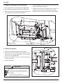
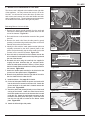
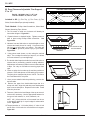
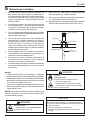
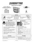
Installation Manual
Installation & Appliance Set-Up
INSTALLER: Leave this manual with party responsible for use and operation.
OWNER: Retain this manual for future reference.
NOTICE: DO NOT DISCARD THIS MANUAL
WARNING
If the information in these instructions is not followed exactly, a
fire may result causing property
damage, personal injury, or death.
3100-I ACC WOOD INSERT
Automatic Combustion Control (ACC)
Model(s):
31-I ACC
• Do not store or use gasoline or other flammable vapors and liquids in the vicinity of
this or any other appliance.
• Do not overfire - If heater or chimney connector glows, you are overfiring. Overfiring
will void your warranty.
• Comply with all minimum clearances to
combustibles as specified. Failure to
comply may cause house fire.
WARNING
Tested and
Listed by
O-T L
C
HOT SURFACES!
Glass and other surfaces are hot
during operation AND cool down.
Hot glass will cause burns.
• Do not touch glass until it is cooled
• NEVER allow children to touch glass
• Keep children away
• CAREFULLY SUPERVISE children in same room as
fireplace.
• Alert children and adults to hazards of high temperatures
• High temperatures may ignite clothing or other
flammable materials.
• Keep clothing, furniture, draperies and other flammable
materials away.
Portland
Oregon USA
US
OMNI-Test Laboratories, Inc.
WARNING
Fire Risk.
For use with solid wood fuel only.
Other fuels may overfire and generate
poisonous gases (i.e. carbon monoxide).
NOTE
Installation and service of this appliance should
be performed by qualified personnel. Hearth &
Home Technologies recommends NFI certified
professionals, or technicians supervised by an
NFI certified professional.
1
To obtain a French translation of this manual, please contact
your dealer or visit www.quadrafire.com
Pour obtenir une traduction française de ce manuel, s’il vous
plaît contacter votre revendeur ou visitez www.quadrafire.com
7044-225
November 6, 2013
31-I ACC
Safety Alert Key:
• DANGER! Indicates a hazardous situation which, if not avoided will result in death or serious injury.
• WARNING! Indicates a hazardous situation which, if not avoided may result in death or serious injury.
• CAUTION! Indicates a hazardous situation which, if not avoided, may result in minor or moderate injury.
• NOTICE: Indicates practices which may cause damage to the appliance or to property.
TABLE OF CONTENTS
1 Important Safety Information
A. Insert Certification..............................................................3
B. BTU & Efficiency Specifications........................................3
C. Mobile Home Approved.....................................................3
D. Glass Specifications..........................................................3
E. Non-Combustible Materials................................................3
F. Combustible Materials.........................................................3
2 Getting Started
A. Design and Installation Considerations...................................4
B. Draft ...............................................................................4
C. Negative Pressure.............................................................5
D. Tools And Supplies Needed...............................................5
E. Inspect Appliance and Components...................................5
F. Install Checklist...................................................................6
3 Dimensions and Clearances
A. Appliance Dimensions.......................................................7
B. Clearances to Combustibles...............................................8
C. Calculating Alternate Floor Protection...............................9
D. Locating Your Stove & Chimney........................................10
E. Chimney Termination Requirements..................................10
F. 2-10-3 Rule .......................................................................11
4 Chimney Systems
A. Venting Systems................................................................12
B. Inspections........................................................................12
C. Larger Chimneys...............................................................12
D. Masonry Chimney.............................................................12
E. Metal Heat Circulating Masonry........................................14
F. Prefabricated Metal Chimney.............................................14
G. Securing Chimney Components.......................................15
H. Altering the Fireplace.........................................................15
I. Zero-Clearance Fireplace...................................................16
J. Ovalizing Round Stainless Steel Liners.............................16
K. Chimney Height / Rise and Run........................................16
5 Appliance Set-Up
A. Outside Air Kit Installation...................................................17
B. Disassemble Firebox and Outer Can................................18
C. Securing Stove Pipe/Liner to Flue Collar..........................19
D. Optional Offset Adapter Installation...................................19
E. Installing Outer Can & Leveling Bolts................................20
F. Surround & Trim Kit Installation..........................................20
G. Installing Firebox into Outer Can.......................................21
H. Securing Appliance to Stove Pipe/Liner............................21
I. Leveling Legs .....................................................................21
J. Snap Disc and Side Panel Installation...............................22
K. Blower Installation.............................................................22
L. Blower Cord Installation on Left Side.................................23
M. Zero Clearance Adjustable Trim Support, 2” to 10” ..........24
6 Mobile Home Installation
7 Accessory List
2
7044-225
November 6, 2013
1
31-I ACC
Important Safety Information
A. Insert Certification
WARNING
Model:
3100-I (ACC) Insert
Laboratory:
OMNI Test Laboratories, Inc.
Report No:
061-S-74-6.2
Type:
Solid Fuel Type, Listed Room Heater
Standard:
UL1482 and ULC S628-93 and
(UM) 84-HUD, Mobile Home
Approved.
Fire Risk.
NOTE: This installation must conform with local codes. In the
absence of local codes you must comply with the UL1482, (UM)
84-HUD and NPFA211 in the U.S.A. and the ULC S628-93 and
CAN/CSA-B365 Installation Codes in Canada.
B. BTU & Efficiency Specifications
EPA Certified:
2.0 grams per hour
Efficiency:
up to 79.8%
EPA BTU Output:
11,800 to 32,000
Heating Capacity:
up to 1800 sq ft depending
on climate zone
Vent Size:
6 inches
Firebox Size:
1.9 cubic feet
Max Wood Length:
18 inches
Max First Hour BTUs:
57,100 @ 75.3% B415
Tested Efficienty
Fuel:
Cord Wood
Shipping Weight:
345 lbs
• Installation and use of any damaged appliance.
• Modification of the appliance.
• Installation other than as instructed by Hearth & Home
Technologies.
• Installation and/or use of any component part not approved by
Hearth & Home Technologies.
• Operating appliance without fully assembling all components.
• Operating appliance without legs attached (if supplied with unit).
• Do NOT Overfire - If appliance or chimney connector glows, you
are overfiring.
Any such action that may cause a fire hazard.
Improper installation, adjustment, alteration, service or
maintenance can cause injury or property damage.
For assistance or additional information, consult a qualified
installer, service agency or your dealer.
NOTE: Hearth & Home Technologies, manufacturer of
this appliance, reserves the right to alter its products, their
specifications and/or price without notice.
Hearth & Home Technologies WILL NOT warranty stoves
that exhibit evidence of over-firing. Evidence of over-firing
includes, but is not limited to:
The Quadra-Fire 3100 Wood Insert (ACC) meets the U.S. Environmental Protection Agency’s 1990 particulate emission standards.
• Warped air tube
• Deteriorated refractory brick retainers
• Deteriorated baffle and other interior components
C. Mobile Home Approved
Hearth & Home Technologies disclaims any
responsibility for, and the warranty will be voided
by, the following actions:
• This appliance is approved for mobile home installations when not installed in a sleeping room and when
an outside combustion air inlet is provided.
E. Non-Combustible Materials
• The structural integrity of the mobile home floor, ceiling, and walls must be maintained.
• The appliance must be properly grounded to the frame
of the mobile home with #8 copper ground wire, and
chimney must be listed to UL103 HT or a listed UL1777 full length six inch (152mm) diameter liner must
be used.
Material which will not ignite and burn, composed of any
combination of the following:
- Steel- Plaster
- Brick- Iron
- Concrete
- Tile
- Glass- Slate
Materials reported as passing ASTM E 136, Standard
Test Method for Behavior of Metals, in a Vertical Tube
Furnace of 750° C.
• Outside Air Kit, part OAK-ACC must be installed in a
mobile home installation.
F. Combustible Materials
D. Glass Specifications
This stove is equipped with 5mm ceramic glass. Replace
glass only with 5mm ceramic glass. Please contact your
dealer for replacement glass.
Quadra-Fire is a registered trademark of Hearth & Home
Technologies.
November 6, 2013
Material made of/or surfaced with any of the following materials:
- Wood
- Compressed Paper
- Plant Fibers
- Plastic
- Plywood/OSB - Sheet Rock (drywall)
Any material that can ignite and burn: flame proofed or not,
plastered or un-plastered.
7044-225
3
31-I ACC
2
Install Guide
Getting Started
B.Draft
A. Design and Installation Considerations
Draft is the pressure difference needed to vent appliances
successfully. When a appliance is drafting successfully, all
combustion byproducts are exiting the home through the
chimney.
CAUTION
Check building codes prior to installation.
• Installation MUST comply with local, regional, state and
national codes and regulations.
Considerations for successful draft include:
• Consult insurance carrier, local building, fire officials or
authorities having jurisdiction about restrictions, installation
inspection, and permits.
• Location of appliance and chimney
To be sure that your appliance burns properly:
• During a low burn, the chimney draft (static pressure) should
be approximately -.04 inch water column (W.C.)
Before installing, determine the following:
•
•
•
• Preventing negative pressure
Type of chimney connector to be used
· single wall, 6 inch (152mm) diameter, stainless steel, or
· double wall, 6 inch (152mm) diameter, stainless steel
Consult page 28 for clearances to combustibles
Power outlet located close by for optional blower
WARNING
• During a high burn the chimney draft should be approximately
-.10 inch (W.C.)
• Measure the W.C at 6 inches (152mm) above the top of the
appliance after one hour of operation at each burn setting.
NOTICE: Hearth & Home Technologies assumes no
responsibility for the improper performance of the
appliance system caused by:
Asphyxiation Risk.
• DO NOT CONNECT THIS UNIT TO A CHIMNEY
FLUE SERVICING ANOTHER APPLIANCE.
• DO NOT CONNECT TO ANY AIR DISTRIBUTION
DUCT OR SYSTEM.
May allow flue gases to enter the house.
• Inadequate draft due to environmental conditions
• Downdrafts
• Tight sealing construction of the structure
• Mechanical exhausting devices
• Overdrafting caused by excessive chimney heights
WARNING
Fire Risk.
Hearth & Home Technologies disclaims any
responsibility for, and the warranty will be
voided by, the following actions:
• Ideal performance is with height of chimney between
14-16 feet (4.26-4.88m) measured from the base of
the appliance.
• Installation and use of any damaged appliance.
• Modification of the appliance.
• Installation other than as instructed by Hearth & Home
Technologies.
• Installation and/or use of any component part not approved
by Hearth & Home Technologies.
• Operating appliance without fully assembling all components.
• Operating appliance without legs attached (if supplied with
unit).
• Do NOT Overfire - If appliance or chimney connector glows,
you are overfiring.
Any such action that may cause a fire hazard.
4
7044-225
November 6, 2013
31-I ACC
C. Negative Pressure
D. Tools And Supplies Needed
Before beginning the installation be sure the following tools
and building supplies are available:
WARNING
Asphyxiation Risk.
• Negative pressure can cause spillage of combustion fumes, soot and carbon monoxide.
• Appliance needs to draft properly for safety.
Negative pressure results from the imbalance of air available for the appliance to operate properly. It can be strongest in lower levels of the house.
Causes include:
• Combustion air requirements for furnaces, water heaters
and other combustion appliances
• Clothes dryers
• Location of return-air vents to furnace or air conditioning
• Imbalances of the HVAC air handling system
• Upper level air leaks such as:
- Attic hatch
- Duct leaks
Pliers
High temp caulking material
Hammer
Gloves
Phillips screwdriver
Framing square
Flat blade screwdriver
Electric drill and bits
Plumb line
Safety glasses
Level
Tape measure
Misc. screws and nails
• Range hoods
- Recessed lighting
Framing material
1/2-3/4 in. length, #6 or #8 self-drilling screws
• Exhaust fans (kitchen, bath, etc.)
Reciprocating saw
E. Inspect Appliance and Components
• Remove appliance and components from packaging and
inspect for damage.
• Vent system components and doors are shipped in
separate packages.
• Report to your dealer any parts damaged in shipment.
• Read all the instructions before starting the
installation. Follow these instructions carefully during
the installation to ensure maximum safety and benefit.
To minimize the effects of negative air pressure:
• Install the outside air kit with the intake facing prevailing
winds during the heating season
• Ensure adequate outdoor air for all combustion appliances
and exhaust equipment
• Ensure furnace and air conditioning return vents are not
located in the immediate vicinity of the appliance
• Avoid installing the appliance near doors, walkways or
small isolated spaces
WARNING
Fire Risk.
Inspect appliance and components for damage.
Damaged parts may impair safe operation.
• Do NOT install damaged components.
• Do NOT install incomplete components.
• Do NOT install substitute components.
Report damaged parts to dealer.
• Recessed lighting should be a “sealed can” design
• Attic hatches weather stripped or sealed
• Attic mounted duct work and air handler joints and seams
taped or sealed
• Basement installations should be avoided
November 6, 2013
7044-225
5
31-I ACC
F. Install Checklist
ATTENTION INSTALLER:
Follow this Standard Work Checklist
This standard work checklist is to be used by the installer in conjunction with, not instead of, the instructions contained in this installation manual.
Customer: Date Installed:
Lot/Address:
Location of Fireplace:
Installer:
Dealer/ Distributor Phone #:
Serial #:
Model (circle one): 31I-ACC
WARNING! Risk of Fire or Explosion! Failure to install fireplace according to these instructions can lead to a fire or explosion.
Appliance Install
Verified clearances to combustibles. (Pg. 8)
Fireplace is leveled and liner is secured to appliance. (Pg. 18)
Hearth extension size/height decided. (Pg. 22)
Outside air kit installed. (Pg. 16)
Floor protection requirements have been met.
The masonry chimney is inspected by a professional and is clean or the
factory built metal chimney is installed according to the manufacturer’s
instructions and clearances.
YES
IF NO, WHY?
Chimney Section 4 (Pg. 11)
Chimney configuration complies with diagrams.
Chimney installed, locked and secured in place with proper clearance.
Chimney meets the minimum height requirements.
Roof flashing installed and sealed.
Terminations installed and sealed.
Clearances Section 3 (Pg. 7)
Combustible materials not installed in non-combustible areas.
Verified all clearances meet installation manual requirements.
Mantels and wall projections comply with installation manual requirements.
Protective hearth strips and hearth extension installed per manual requirements.
Appliance Setup Section 5 (Pg. 16)
All packaging and protective materials removed.
Firebrick, baffle and ceramic blanket installed correctly.
All labels have been removed from the door.
All packaging materials are removed from inside/under the fireplace.
Manual bag and all of its contents are removed from inside/under the fireplace
and given to the party responsible for use and operation.
Hearth & Home Technologies recommends the following:
• Photographing the installation and copying this checklist for your file.
• That this checklist remain visible at all times on the fireplace until the installation is complete.
Comments: Further description of the issues, who is responsible (Installer/Builder/Other Trades, etc.) and corrective action needed:
Comments communicated to party responsible
by
on
(Builder/Gen. Contractor) (Installer) (Date)
Part # 4017-254 • Rev B • 01/29/13
6
7044-225
November 6, 2013
3
31-I ACC
Dimensions and Clearances
A. Appliance Dimensions
NOTE: Flue Collar size is 6 inch (152mm) diameter (ID)
A
27-5/8 in (702mm)
23-13/16 in (589mm)
5-11/16 in (144mm)
CL
8-1/2 in (216mm)
5-1/2 in (140mm)
B
38-9/16 in (979mm)
Figure 7.1 Top View
Figure 7.2 Front View
A
Surround Sizes
23-1/4 in (591mm)
B
Standard
43 in. (1092mm)
31 in. (787mm)
Large
53 in. (1346mm)
34 in. (864mm)
16-5/16 in. to 19-5/8 in.
(414mm to 498mm)
14-1/4 in
(362mm)
11-7/8 in. to 15-3/16 in.
(302mm to 386mm)
4 in.
(102mm)
CL
21-1/2 in
(546mm)
20-7/16 in
(519mm)
24-3/16 in.
(614mm)
12-1/2 in
(318mm)
7-3/4 in (197mm)
26-3/4 in (679mm)
Figure 7.3 - Side View
November 6, 2013
Figure 7.4 - Side View With Optional Offset Adapter
7044-225
7
31-I ACC
B. Clearances to Combustibles
United States and Canada (UL and ULC)
32-1/4
819mm
27-1/4
692mm
SIDE TRIM
SIDE WALL
TOP TRIM
40-11/16
1033mm
USA 16-3/4
CANADA
24-3/4 (629mm)
HEARTH
EXTENSION
MANTEL
USA 23-1/2
CANADA 25-1/2 (648mm)
43-11/16
1110mm
FIREPLACE FRONT SURFACE
12in max
THERMAL PROTECTION
USA & CANADA
Floor height 0” to 6-1/2”
(6mm to 165mm) below
insert base
1-1/2 inch (38) of k=3.06
Floor height greater than
6-1/2” (165mm) below insert
base
1 inch (25) of k = 0.49, R = 2.04
HEARTH EXTENSION
See next page for thermal protection
calculations
In Canada a full length 6 inch (152mm) S635 flue liner required as per ULC S628.
In USA a minimum 5 ft length (1.82m), 6 inch (152mm) diameter flue liner is required as per UL 1482.
WARNING
Fire Risk.
• Comply with all minimum clearances to
combustibles as specified.
• Failure to comply may cause house fire.
8
NOTE: Clearances may only be reduced by
means approved by the regulatory authority
having jurisdiction
7044-225
November 6, 2013
31-I ACC
Zero Clearance Floor Thermal Protection
C. Calculating Alternate Floor Protection
Material
Thermal Conductivity: k value
The k value indicates the amount of heat (in BTU’s) that will flow
in 1 hour through 1 square foot of a uniform material 1 inch thick
for each degree (F) of temperature difference from one side of
the material to the other.
ZERO
CLEARANCE
ONLY
The LOWER the k factor means less heat is being conducted
through the non-combustible material to the combustible material beneath it.
Required
Thermal
Protection
1 inch (25mm)
1-1/2 inch (38mm)
Adj. Hearth
Support
0 to 6-1/2 inch
(0 to 165mm)
The k value of a material must be equal or smaller then the required k value to be acceptable.
(BTU) (inch)
(foot2 (hour) (oF)
Thermal Resistance: R value
The R value is a measure of a material’s resisteance to heat
transfer.
1-1/2 inch (38mm)
R value is convenient when more than one material is used
since you can add the R values together, whereas you can
not do this for k value.
The HIGHER the R factor means less heat is being conducted through the non-combustible material to the combustible
material beneath it.
Figure 9.1
The R value of a material must be equal or larger then the
required R value to be acceptable.
Converting k to R:
Divide 1 by k and multiply the results times the thickness in inches of the material.
ZERO
CLEARANCE
ONLY
Converting R to k:
Divide the inches of thickness by R.
Required
Thermal
Protection
6-1/2 inch
(165mm)
Adj. Hearth
Support
k = inches of thickness/R
Calculatons:
Example: Floor protection requires k value of 0.84 and 3/4 inch
thick.
1 inch (25mm)
1 inch
(25mm)
R = 1/k x inches of thickness
Alternative material has a k value of 0.6 and is 3/4 inch thick.
Divide 0.6 by .75 = k value of 0.80. This k value is smaller than
0.84 and therefore is acceptable.
1-1/2 inch (38mm)
Figure 9.2
November 6, 2013
7044-225
9
31-I ACC
D. Locating Your Stove & Chimney
Location of the appliance and chimney will affect performance. As shown in Figure 10.1 the chimney should:
• Install through the warm space enclosed by the building envelope. This helps to produce more draft, especially during lighting and die down of the fire.
• Penetrate the highest part of the roof. This minimizes
the affects of wind turbulence and down drafts.
Recommended
Location
Location
Not
Recommended
• Consider the appliance location in order to avoid floor
and ceiling attic joists and rafters.
• Locate termination cap away from trees, adjacent
structures, uneven roof lines and other obstructions.
Your local dealer is the expert in your geographic area and
can usually make suggestions or discover solutions that will
easily correct your flue problem.
Recommended
Location
Marginal
Location
Location NOT
Recommended
Windward
Leeward
Outside Termination Cap
Multi-level Roofs
Figure 10.1
E. Chimney Termination Requirements
Follow manufacturer’s instructions for clearance, securing
flashing and terminating the chimney.
• Must have an approved and Listed cap
• Must not be located where it will become plugged by
snow or other material
• Must terminate at least 3 feet (91cm) above the roof
and at least 2 feet (61cm) above any portion of the
roof within 10 feet (305cm).
• Must be located away from trees or other structures
NOTICE: Locating the appliance in a basement or in a
location of considerable air movement can cause intermittent
smoke spillage from appliance. Do not locate appliance near
• Frequently open doors
• Central heat outlets or returns
NOTICE:
• Chimney performance may vary.
• Trees, buildings, roof lines and wind conditions affect
performance.
• Chimney height may need adjustment if smoking or
overdraft occurs.
10
7044-225
November 6, 2013
31-I ACC
F. 2-10-3 Rule
These are safety requirements and are not meant to assure proper flue draft.
This appliance is made with a 6 inch (152mm) diameter chimney connector as the flue collar on the unit.
• Changing the diameter of the chimney can affect draft and cause poor performance.
• It is not recommended to use offsets and elbows at altitudes above 4000 feet above sea level and or when there are other factors that affect flue draft.
Less than 10 ft. (305cm)
2 ft. (61cm)
2 ft. (61cm)
10 ft. (305cm) To Nearest Roofline
3 ft. (91cm)
Minimum
3 ft. (91cm)
Minimum
Pitched Roof
Figure 11.1
10 ft. (305cm) or more
Less than 10 ft. (305cm)
Wall or Parapet
2 ft. (61cm) Minimum
3 ft. (91cm) Minimum
3 ft. (91cm) Minimum
Flat Roof
Figure 11.2
November 6, 2013
7044-225
11
31-I ACC
4
Chimney Systems
A. Venting Systems
D. Masonry Chimney
It is also known as flue pipe or stove pipe. It must be 6 inches
(152mm) minimum diameter stainless steel connector pipe.
•Must have at least 5/8 inch (16mm) fireclay lining joined
with refractory cement. (Installations into a clay flue
without a stainless steel liner may reduce draw which
affects performance, will cause the glass to darken and
produce excessive creosote).
Chimney Connector:
•Must meet minimum standards of NFPA 211.
Chimney:
The chimney can be new or existing, masonry or prefabricated
and must meet the following minimum requirements as
specified below.
•The masonry wall of the chimney, if brick or modular
block, must be a minimum of 4 inches (102mm) nominal
thickness.
•A chimney of rubble stone must be at least 12 inches
(305mm) thick.
WARNING! Risk of Fire!
•Cross-sectional area shall conform to NFPA 211-2006
Section 12.4.5.1.
Follow venting manufacturer’s clearances and
instructions when installing venting system.
B. Inspections
Existing chimneys should be inspected and cleaned by a
qualified professional prior to installation. The chimney must
not have cracks, loose mortar or other signs of deterioration
and blockage. Hearth & Home recommends a NFI or CSIA
certified professional or a technician, under the direction of
a certified professional, conduct a Level II inspection per
NFPA 211.
•Should be lined with a 6 inch (152mm) stainless steel
flue liner to improve performance and reduce creosote
build-up.
•An equivalent liner must be a listed chimney liner system
or other approved material.
•No dilution air is allowed to enter the chimney.
1. Secure the fireplace damper in the open position. If
this cannot be accomplished, it will be necessary to
remove the damper
2.Seal damper area of chimney around chimney
connector with a high temperature sealant or seal
insert against the face of the fireplace.
WARNING
Fire Risk
Inspection of Chimney:
• Chimney must be in good condition.
• Meets minimum standard of NFPA 211
• Factory-built chimney must be 6 inch
(152mm) UL103 HT.
3.Both methods must be removable and replaceable
for cleaning and re-installation.
•When possible, install an airtight clean-out door to the
rear of the smoke shelf.
C. Larger Chimneys
It is recommended that chimneys with larger diameters
than 6 inches (152mm) be relined. An oversized flue can
affect draft and impair performance and will allow increased
build-up of creosote.
NOTICE: Check with your local building authorities
and/or consult the National Fire Protection Association
(NFPA 211).
12
7044-225
November 6, 2013
31-I ACC
Masonry Chimney (Cont’d)
This insert conforms with the UL 1482 and ULC S628
(Canada) in all respects, and is approved to UL & ULC
safety standards for installation and use within a fireplace
with a masonry chimney in accordance with NFPA 211 and
CAN/CSA-B365-01.
UL 1777 Insulated Stainless Steel
Liner or Other Approved Lining System
Follow Manufacturer’s Instructions
on Insulation and Support
For Zero or Other Non-Code Clearances,
Follow Approved Liner Manufacturer’s Specific
Insulation Requirements: Different Clearances
May Require Different Specifications
NOTE: In Canada, this fireplace insert must be installed
with a continuous chimney liner of a 6 inch (152mm) diameter extending from the fireplace insert to the top of the
chimney. The chimney liner must conform to the Class 3
requirements of CAN/ULC-S635, Standard for Lining Systems for Existing Masonry or Factory-Built Chimneys and
Vents, or CAN/ULC-S640, Standard for Lining Systems
for New Masonry Chimneys.
Follow Manufacturer’s
Instructions for Maximum
Liner Extension Above
Chimney
Maximum 30 Degrees
Offset in Chimney
Masonry Chimney Must
Have Structural Integrity
UL 1777 Insulated Stainless Steel
Liner or Other Approved Lining System
Minimum 8 in. (203mm) Masonry
Thickness in Front of Smoke Chamber
Minimum Clearance in Accordance
with Insert Listing
Floor Protection in
Accordance with Insert
Listing
Damper Plate Removed or
Fastened in Open Position
Seal with Non-Combustible Material
Combustible Floor
Figure 13.1
Generic Insert Model Shown in Illustration
November 6, 2013
7044-225
13
31-I ACC
E. Metal Heat Circulating Masonry
This insert conforms with the safety standard UL-1482 and
ULC S628 (Canada) in all respects and is approved to UL &
ULC safety standards for installation and use within a fireplace with masonry chimney, in accordance with NFPA 211,
with a direct flue collar connection. F. Prefabricated Metal Chimney
The chimney can be new or existing, masonry or prefabricated
and must meet the following minimum requirements:
•Must be minimum 6 inch (152mm) inside diameter of
high temperature chimney listed to UL 103 HT (2100oF)
or ULC S628.
•Must use components required by the manufacturer for
installation.
•Must maintain clearances required by the manufacturer
for installation.
•Refer to manufacturers instructions for installation
•This insert is listed to UL 1482 Standard and is approved
for installation into listed factory-built zero clearance fireplaces listed to UL 127 conforming to the following specifications and instructions:
•The original factory-built clearance fireplace chimney
cap must be re-installed after installing the approved
chimney liner meeting type UL 103 HT requirements
(2100°F) per UL 1777.
•If the chimney is not listed as meeting HT requirements,
or if the factory built fireplace was tested prior to 1998, a
full height listed chimney liner must be installed from the
appliance flue collar to the chimney top.
•The liner must be securely attached to the insert flue collar
and the chimney top.
•The air flow of the factory-built zero-clearance fireplace
system must not be altered. The flue liner top support
attachment must not reduce the air flow for the existing
air-cooled chimney system.
•No dilution air is allowed to enter the chimney.
1. Secure the fireplace damper in the open position. If
this cannot be accomplished, it will be necessary to
remove the damper
2.Seal damper area of chimney around chimney
connector with a high temperature sealant or seal
insert against the face of the fireplace.
3.Both methods must be removable and replaceable
for cleaning and re-installation.
Flue Liner with Required Air Space
Stainless Steel Chimney Connector
Must Extend to Flue Liner
Minimum 8” (203mm) Masonry Thickness
in Front of Smoke Chamber
Airtight Insulated Clean-Out
Minimum Clearance in Accordance with
Insert Listing
Damper Plate Removed or
Fastened in Open Position
Floor Protection in
Accordance with Insert
Listing
Seal with NonCombustible Material
Combustible Floor
Figure 14 .1
Generic Insert Model Shown in Illustration
14
7044-225
November 6, 2013
31-I ACC
Prefabricated Metal Chimney (Cont’d)
H. Altering the Fireplace
Inches
Millimeters
Minimum Width of Cavity Opening - Front
29-1/16
738
Minimum Width of Cavity Opening - Rear
25-1/2
648
Minimum Height
20-3/4
528
Minimum Depth from Front to Rear
17-9/16
446
NOTE: Refer to chimney liner manufacturer for recommendations on supporting the liner. Installation into
fireplaces without a permit will void the listing.
NOTICE: In Canada when using a factory-built chimney it must be safety listed, Type UL103 HT (2100oF)
[1149oC] CLASS “A” or conforming to CAN/ULCS629M, STANDARD FOR 650oC FACTORY-BUILT
CHIMNEYS.
WARNING
Fire Risk.
When lining air-cooled factory-built chimneys:.
• Run chimney liner approved to UL 1777 Type
HT requirements (2100 degrees F)
• Re-install original factory built chimney cap
ONLY
• DO NOT block cooling air openings in chimney
• Blocking cooling air will overheat the chimney
Damper
Smoke Shelf or Baffle
Ember Catches
Fire Grate
Viewing Screen/Curtain
Doors
• The fireplace must not be altered. Cutting any sheet metal
parts of the fireplace in which the fireplace insert is to be
installed is prohibited per ANSI Z21.88 except that the
damper may be removed to accommodate a direct-connect
starter pipe or chimney liner,
• External trim pieces which do not affect the operation of
the fireplace may be removed providing they can be stored
on or within the fireplace for reassembly if the insert is
removed.
• The permanent metal warning label provided in the
component pack must be attached to the back of the
fireplace, with screws or nails, stating that the fireplace may
have been altered to accommodate the insert, and must
be returned to original condition for use as a conventional
fireplace. Figure 15.2.
• If the hearth extension is lower than the fireplace opening,
the portion of the insert extending onto the hearth must be
supported.
• Manufacturer designed adjustable support kit can be
ordered from your dealer.
G. Securing Chimney Components
All joints should be secured with 3 sheet metal screws or
rivets per pipe manufacturers instructions. The sections must
be attached to the insert and to each other with the crimped
(male) end pointing toward the insert. Figure 15.1.
• Final approval of this installation type is contingent upon
the authority having jurisdiction.
WARNING
THIS FIREPLACE MAY HAVE BEEN ALTERED
TO ACCOMMODATE AN INSERT. IT MUST BE
RETURNED TO ITS ORIGINAL CONDITION
BEFORE USE AS A SOLID FUEL BURNING
FIREPLACE.
250-2061
250-2061
LINER CONNECTOR
CRIMPED
END
TOWARDS
STOVE
The following modifications of factory-built fireplaces are
permissible:
The following parts may be removed:
Figure
15.3
Heath
& Home
Technologies
250-2061
5.5 in. width x 2 in. height
FLUE
GAS
DIRECTION
NON. ANOD. ALUM BLACK LETTERS ON SILVER
with 1/8 in. holes on both sides.
Black letters
Figure 15.1
WARNING! Risk of Fire!
Follow venting manufacturer’s clearances and instructions
when installing venting system.
November 6, 2013
7044-225
15
31-I ACC
I. Zero-Clearance Fireplace
J. Ovalizing Round Stainless Steel Liners
A permit may be required for installations, final approval is
contingent of the authority having local jurisdiction. Consult
insurance carrier, local building, fire officials or authorities
having jurisdiction about restrictions, installation inspection,
and permits.
Ovalizing round stainless steel liners to accommodate the
liner passing through the damper region of a fireplace is an
allowable and acceptable practice.
Inspect the existing fireplace and chimney for any damage
or flaws such as burnouts, metal or refectory warping.
K. Chimney Height / Rise and Run
Inspection to a minimum of NFPA 211 Level II is recommended. All repairs must be made prior to installing an
insert. The fireplace must be structurally sound and be able
to support the weight of the solid-fuel insert
The factory-built chimney must be listed per UL 127 or ULC
610-M87 for all installations. Install thermal protection per
this appliance listing requirements.
A full height 6 inch diameter stainless steel full height
listed chimney liner must be installed meeting type HT
(2100°F) requirements per UL 1777 (USA) or ULC S635
with “0” clearance to masonry (Canada). The full liner
must be attached to the insert flue collar and to the top
of the existing chimney.
The flue liner top support attachment must not reduce the air
flow for the existing air-cooled chimney system. Re-install
original factory-built chimney cap only. (See Section F.,
Prefabricated Metal Chimney)
To prevent room air passage to the chimney cavity of the
fireplace, seal either the damper area around the chimney
liner or the insert surround. Circulating air chamber (i.e. in
a steel fireplace liner or metal hearth circulator) may not be
blocked. The air flow within and around the fireplace shall
not be altered, blocked by the installation of the insert. (i.e.
no louvers or cooling air inlet or outlet ports may be blocked
by the insert or the insert surround.
See “H. Altering the Fireplace” for modifications allowed for
factory-built fireplaces.
Ensure that the ovalization is minimized to the extent
required to fit through the damper.
To be sure that your Quadra-Fire insert burns properly, the
chimney draft (static pressure) should be approximately -0.10
inches water column (W.C.) during a high burn and -0.04
inches W.C. during a low burn, measured 6 inches (152mm)
above the top of the insert after one hour of operation at each
burn setting.
NOTE: These are guidelines only, and may vary somewhat
for individual installations.
• This product was designed for and tested on a 6 inch
(152mm) chimney, 14 to 16 feet (4.27-4.87m) high, (includes appliance height) measured from the base of the
appliance.
• The further your stack height or diameter varies from this
configuration, the possibility of performance problems exists.
• Chimney height may need to be increased by 2 - 3% per
each 1000 feet (304.8m) above sea level.
• It is not recommended to use offsets or elbows at altitudes
above 4000 feet (1219.2m) above sea level or when there
are other factors that affect flue draft.
WARNING
Fire Risk.
Do NOT pack insulation or other combustibles
between spacers.
• ALWAYS maintain specified clearances around
venting and spacers.
• Install spacers as specified.
Failure to keep insulation or other material away
from vent pipe may cause fire.
WARNING! Risk of Asphyxiation!
• DO NOT CONNECT THIS APPLIANCE TO
A CHIMNEY FLUE SERVICING ANOTHER
APPLIANCE OR TO ANY AIR DISTRIBUTION
DUCT OR SYSTEM.
This may allow flue gases to enter the house.
WARNING
Fire Risk.
This appliance relies upon natural draft to operate
properly.
• Chimney heights exceeding 25 feet (7.62m) from
base of appliance may create an over-draft
situation.
• Overdraft condition may create over-firing.
Over-firing may ignite creosote and/or damage
appliance and chimney
16
7044-225
November 6, 2013
5
31-I ACC
Appliance Set-Up
A. Outside Air Kit Installation
A source of air (oxygen) is necessary in order for combustion
to take place. Whatever combustion air is consumed by the
fire must be replaced. Air is replaced via air leakage around
windows and under doors. In homes that have tightly sealed
doors and windows, an outside air source is needed. An optional
Outside Air Kit is available.
Fire Risk.
Asphyxiation Risk.
Do not draw outside combustion air from:
• Wall, floor or ceiling cavity
• Enclosed space such as an attic or garage
• Close proximity to exhaust vents or
chimneys
Fumes or odor may result
Items Needed for Installation (not supplied)
• 4 inch flex aluminum pipe, or if using alternate material,
then it shall be made from durable, non-combustible, heat
resistant material up to 350oF. Cut the pipe to the required
length for your installation.
• Phillips head screw driver
• 5/32 Allen Wrench
• Silicone sealant
Option One - Installation Instructions
The outside air cover comes packaged with the component
pack. It is necessary to remove the blower housing and block
off the room air with the outside air cover.
WARNING
Asphyxiation Risk.
Outside air inlet must be located to prevent blockage from:
• Leaves, snow, ice or other debris
Block may cause combustion air starvation
Smoke spillage may set off alarms or irritate sensitive individuals.
1. Remove the appliance cover plate on outer can and discard
and reuse the 4 screws.
2. Install optional flex adapter to outer can with the same
screws. Do not use plastic wire ties that come with the kit
as they will melt. NOTE: You may need to install the flex
pipe into the firebox first depending on installation. Attach
flex to adapter with at least 2 screws.
3. Ensure existing access hole in fireplace is sufficient to feed
the 4 inch flex.
WARNING
WARNING
Asphyxiation Risk.
Length of outside air supply duct shall NOT exceed
the length of the vertical height of the exhaust flue.
• Fire will not burn properly
• Smoke spillage occurs when door is opened due
to air starvation.
4. After sliding can into fireplace, feed flex into cut opening to
obtain outside combustion air.
5. Level outer can and install appliance. See page 20.
Outside Air
Cover Plate
6. Remove 4 bolts from both sides of the blower housing and
remove the housing.
(Discard)
7. Remove 2 Phillips head screws from housing and save.
8. Attach outside air cover to the back of the blower using the
same 2 screws.
9. Ensure all wires are properly attached and then re-install
the blower housing to the appliance.
Flex Adapter
Option Two - Installation Instructions
Termination
Cap
Rectangular Outside Air
Cover (included with Side
1. Remove the outside air cover plate on outer can and discard and reuse the 4 screws
Panel Assembly)
2. Ensure existing access hole in fireplace will not be covered
by the outer can. Existing outside air intake hole may be
under at the rear or side of outer can. Outside air may also
enter down existing chimney chase in some situations.
3. Repeat steps 5 through 9 above with one exception. After
installing the appliance in the outer can, seal the fireplace
opening and trim package with insulation to prevent air leakage into the room.
November 6, 2013
Figure 17.1
7044-225
17
31-I ACC
B. Disassemble Firebox and Outer Can
For easier field installation the outer can is installed without the firebox so connecting to the flue has greater access. The firebox slides into the outer can once the flue collar is
attached to the stove pipe/liner and optional outside air flex
pipe is installed.
1. Remove the flue collar by cutting the wire ties. Set the
flue collar and attachment bar aside.
2. Remove the 2 screws holding the timer assembly in place
and remove the timer. Figure 18.1.
3. Remove the 2 Phillips head bolts underneath the ashlip
which holds the firebox in place.
Timer Screws
4. Slide the firebox out of the outer can.
5. Remove the 2 pallet lag bolts.
Figure 18.1
Flue Collar
Attachment Bar
Outer Can
Pallet
Lag
Bolts
Timer Assembly
Firebox
Phillips Head Bolts
Figure 18.2
18
7044-225
November 6, 2013
31-I ACC
C. Securing Stove Pipe/Liner to Flue Collar
Cast Iron Flue Located on Appliance
1.There are 4 pre-drilled holes in the flue collar 90 degrees
apart. Attach the flue collar to the stove pipe/liner. If the
seal is questionable use high temperature sealant such
as stove mastic Figure 19.1.
2.Attach gasket to bottom side of flue collar with a thin coat
of silicone.
Drill through all 8 countersunk
locations
Figure 19.2
Gasket
Flue Collar
Stove Pipe/Liner
Figure 19.1
D. Optional Offset Adapter Installation
In some installations the flue collar and stove pipe/liner do
not always align properly. This situation may be remedied
by using the optional offset adapter. See Appliance Dimensions page for the amount of distance this accessory can
telescope between the flue collar and stove pipe/liner.
Figure 19.3
1.Remove the cast iron flue collar from the appliance and
flip it upside down. Using the larger #7 drill bit supplied,
drill through all 8 countersunk locations. Figure 19.2.
2.Slide the gasket over the flue collar and attach it to the
offset adapter using the 8-32 flathead screws provided. Figure 19.3.
3.Adjust the offset adapter to desired distance. Drill holes
through the lower chamber as shown in Figure 19.4
using the small drill bit #26 provided.
4.Cut the gasket to the proper length and slide in between
the upper and lower chambers centered on the screw
holes. Attach the upper and lower chambers with screws
provided. Figure 19.5.
Once distance is established, drill holes
and secure both chambers together.
Figure 19.4
5.Repeat the process on the bottom side.
Figure 19.5
November 6, 2013
7044-225
19
31-I ACC
E. Installing Outer Can & Leveling Bolts
F. Surround & Trim Kit Installation
1. Align the back of surface of outer can side panels to the
front wall surface for proper placement. Figure 20.2.
Use the leveling bolts to level the outer can. Figure 20.1.
1. Lay surround face down on a protected surface to prevent scratching.
3. Thread the horizontal support bolts in until they hit the
back wall of the fireplace to help secure in place. Figure
20.3.
4. It is recommended that you use the pallet mounting holes
to lag the outer can into the fireplace floor for extra support, however it is not required.
2.Using a Phillips head screw driver attach the side surrounds to the top surround using 2 #8 sheet metal screws
provided with the kit. Figure 20.4.
3. Lay the trim face down and place the corner brackets into
position.
4. Using a standard flat screw driver tighten the corner
brackets. Figure 20.5.
5. Slide the trim over the surround set.
6.Install the surround set and trim set to the outer can.
Secure the top and side surrounds as shown in Figure
20.6.
Outer Can Side Panels
Wall
Horizontal
Support Bolts
Leveling Bolts
Figure 20.1
Wall
Secure 2 Side Surrounds to
Top Surround
Attachment Holes to Outer Can
Figure 20.4
Wall
Outer Can
Side Panel
Figure 20.5
Corner Brackets
Figure 20.2
Back Wall
Top Surround
Side Surround
# 8 Screws
Horizontal Support
Bolts
Figure 20.3
20
Figure 20.6
7044-225
November 6, 2013
31-I ACC
G. Installing Firebox into Outer Can
H. Securing Appliance to Stove Pipe/Liner
For easier installation, remove the baffle protection channel, tube channel assembly, baffle board and ceramic blanket from the appliance before installing into the outer can.
See Owner’s Manual for instructions.
1. Once you have the appliance in place and secured, reach
up through the flue opening and grab the attachment bar
and pull down inside flue opening. Figure 21.3.
1.Slide the appliance into the outer can. Secure with
Phillips head bolts previously removed from under the
ashlip. Figure 21.1.
2. Re-install the timer assembly. The timer arm must be
between the first and second control arm tabs. Figure
21.2.
3. Attach the timer arm to the timer door.
2. Insert the 5/16 bolts inside the cast flue and through the
chimney mounting bar. Securely tighten the nuts. Fasteners are provided.
3. Re-install the tube channel assembly, baffle board,
ceramic blanket and baffle protection channel.
Chimney Mounting Bar
Attachment Bar
4. Test the controls to ensure the timer operates correctly.
Figure 21.3
I. Leveling Legs
1. Remove the 2 screws already installed on each leg.
Phillips Head Bolts
2. Move legs to the desired height.
3. Re-install the screws to secure in place.
Figure 21.1
Timer Arm
Timer Door
Control Arm Tabs
Figure 21.2
November 6, 2013
Figure 21.4
Remove 2 screws from both sides.
Adjust the legs up or down to level
appliance.
7044-225
21
31-I ACC
J. Snap Disc and Side Panel Installation
1. Place snap disc box in location shown in Figure 22.1.
2. Secure the wires through the wire clip to keep in place.
3. Route the blower wires underneath appliance through the
wire channel to the other side of the appliance.
4. Tilt the side panel forward under the top and push the
panel onto the pegs on the face.
5. Attach the side panel to the appliance with 2 screws, 1 at
the top and 1 at the bottom on the right side of panel.
6. Repeat for other side once the blower has been installed.
Side Panel
Screws
Face Pegs
Blower Wires
Figure 22.1
Wire Clip
Wire Channel
Snap Disc Box
K. Blower Installation
1. Remove top and bottom screw from inner panel.
2. Slide blower mount with blower attached behind the face
and secure with 5 screws provided, 3 on the right side
and 2 on the left. Figure 22.2.
3.Connect the blower to the wire harness and secure
through the wire clip.
Blower
Mounting
Screws
Left Side
Panel Screws
4. Install left side panel.
CAUTION
Shock Risk.
• Do NOT remove grounding prong from plug.
• Plug directly into properly grounded 3 prong
receptacle.
• Route cord away from appliance.
• Do NOT route cord under or in front of appliance.
22
Inner Panel
Wire Clip
Figure 22.2
7044-225
November 6, 2013
31-I ACC
L. Blower Cord Installation on Left Side
The blower cord is shipped to be installed on the right side
of the appliance. You may relocate the cord so it is on the
left side. You will need to remove the wires, flip them over
and remove and reverse the male and female terminals
and re-install the wires. The wire harness and components
are located on the back side of the right side panel.
Green Ground
Wire & Nut
Strain
Relief
Relocating Blower Cord to Left Side
1.Remove the green ground terminal from the stud and
unhook the neutral (white) and line power wires from the
rest of the harness. Figure 23.1.
Disconnect wires
from wire harness
Figure 23.1
Clip all 3 zip ties
2. Re-install the nut on the stud after removal of the ground
terminal.
3.Remove the strain relief from the side panel by gently
pressing in the tabs using needle nose pliers on the wire
harness side portion the strain relief.
4. Identify the wire with the male spade terminal (this was
originally connected to the white (neutral) lead on the
power cord) and carefully clip the three small zip ties that
connect it to the rest of the harness. Figure 23.2
Male Spade
Terminal
Figure 23.2
5. Once this wire is removed from the harness reverse the
wire so that the female spade terminal is pointing towards
the rest of the harness.
6.Re-attach this wire using the small zip ties supplied in
roughly the same locations that you removed earlier.
Leave the male spade terminal 5 inches (127mm) longer
than the female spade terminal that is already attached to
the harness. Figure 23.3.
Male Terminal Wire 5
inches (127mm) Longer
Male Terminal
Female Terminal
Figure 23.3
7. Attach the female spade terminal to the black wire that
comes out of the speed control. Figure 23.4.
Speed
Control
8. Route the long lead wires from the right side of the unit in
the wire channel that is under the unit.
9. Install the blower. See page 21 for details.
10. On the left side panel attach the power cord strain relief
into the hole that is located on the lower left. Attach the
ground terminal to the stud that is located nearest the
power cord. Figure 23.5.
11. Attach the white lead (neutral) directly to one of the leads
coming off the blower. Attach the other blower lead to
the female spade connector to the harness that is routed
under the unit. Attach the male spade connector on the
harness to the black power wire (line). Route the wires
into the wire clip that is located on the blower mount
plate. Figure 23.5.
Attach Female Terminal
to Black Wire
Figure 23.4
Strain Relief
White (neutral) Wire
12. Attach the left and right side panels.
Green Ground
Wire & Nut
Figure 23.5
November 6, 2013
7044-225
23
31-I ACC
M. Zero Clearance Adjustable Trim Support,
2” to 10”
EXPLODED VIEW OF SCISSORS
Part No. 841-0990, size 9” x 45” and
Part No. ADJSPT-12, size 12” x 50”
SCREWS ARE CIRCLED
Included in Kit: (1) Trim Top, (1) Trim Front, (2) Trim
Sides, Double-Sided Tape (already installed)
Tools Needed: Phillips Head Screwdriver, Sheet Metal
Shears, Measuring Tape, Gloves
DOUBLE-SIDED TAPE
DOUBLE-SIDED TAPE
Figure 24.1
1. The 10 screws on each set of scissors will already be
loose when shipped. Figure 24.1.
2. Expand scissors to desired height. Tighten screws to
hold in place using Phillips Head screwdriver. See
Figure 24.2.
3. Measure front and side trims to required height to cover
scissors and mark pieces for cutting. Cut excess material from top of trims edge, not bottom. This edge will
be sharp; wear gloves to prevent injury to your hands.
Figure 24.2.
4. Using sheet metal shears, cut trim along the marked
edge. The cut edge fits under lip of top trim, so it allows
for some variance in your straight edge.
EXPAND SCISSORS TO DESIRED HEIGHT
INSTALL FRONT TRIM LAST.
CORNERS OVERLAP SIDE
TRIM PIECES
Figure 24.2
5. The double-sided tape that holds front and side trims to scissors has a particularly powerful bonding adhesive.
Adjustments are extremely difficult once trim has adhered
to tape. Do a dry run first without removing paper from
tape.
Decorative tile may
be installed
6. Place cut edge of trim under top lip and into position on
scissors. Place side pieces on first and then front piece. The front piece overlaps side pieces. NOTE: The trim in
the Flush Mount Kit is one piece.
7. Once you are satisfied with the positioning, remove trim
and set aside.
CUT TOP EDGE OF TRIM,
NOT BOTTOM EDGE
Figure 24.3
8. Remove the paper from double-sided tape that is to
accept trim side. Align side and then press hard against
tape to secure side piece. Repeat for other side. Install
front trim piece last.
9. There are 3 holes in the back flange of the top to secure it
to the wall if necessary. Use the appropriate fastener for
the type of wall material, i.e., brick, sheetrock, etc.
NOTE: 3/8” ( 9.5mm) thick tile or like material can be cut
to size and fit under lip of top trim edge for a decorative
touch. Figure 24.3.
10.Thermal protection of 1-1/2 inches (38mm), “k” value of 0.49
and R value of 3.06 under the zero-clearance trim support.
Figure 24.4.
24
Thermal
Protection
Figure 24.4
7044-225
November 6, 2013
6
1.
31-I ACC
Mobile Home Installation
An outside air inlet must be provided for combustion and
must remain clear of leaves, debris, ice and/or snow. It
must be unrestricted while unit is in use to prevent room
air starvation which can cause smoke spillage and an
inability to maintain a fire. Smoke spillage can also set
off smoke alarms.
2. Unit must be secured to the mobile home structure at
two attachment points. Remove bolts from each side
of insert and use plumbers tape to secure to structure
(a washer may be required). Re-install bolts.
3.
Unit must be grounded with #8 solid copper grounding
wire or equivalent and terminated at each end with N.E.C.
approved grounding device.
4.
The factory-built fireplace must meet (UM)84-HUD
requirements for outside combustion air supply to
the fireplace fire chamber and the chimney must be
listed to UL103 HT or a listed UL-1777 full length six
inch (152mm) diameter liner must be used. It must be
equipped with a spark arrestor cap and the outside air
must be installed on the insert.
8.
Burn wood only. Other types of fuels may generate
poisonous gases (e.g., carbon monoxide).
9.
If unit burns poorly while an exhaust blower is on in home,
(i.e., range hood), increase combustion air.
10. Installation shall be in accordance with the Manufacturers
Home & Safety Standard (HUD) CFR 3280, Part 24.
Spark Arestor Cap
Storm Collar
Roof Flashing
Joist Shield/Firestop
Double Wall
Connector Pipe
5. Refer to pages 7-8 of this manual for clearance to
combustibles and floor protections requirements. All
clearances must be followed precisely.
6. Use silicone to create an effective vapor barrier at
the location were the chimney or other component
penetrates to the exterior of the structure.
7.
Figure 25.1
Follow the chimney and chimney connector manufacturer’s
instructions when installing the flue system for use in a
mobile home.
NOTICE:
• Offsets from the vertical, not exceeding 45°, are allowed
per Section 905(a) of the Uniform Mechanical Code (UMC).
• Offsets greater than 45° are considered horizontal and are
also allowed, providing the horizontal run does not exceed
75% of the vertical height of the vent.
• Construction, clearance and termination must be in compliance with the UMC Table 9C. This installation must also
comply with NFPA 211.
WARNING
Fire Risk.
Asphyxiation Risk.
Do not draw outside combustion air from:
• Wall, floor or ceiling cavity
• Enclosed space such as an attic or garage
• Close proximity to exhaust vents or chimneys.
Fumes or odor may result
NOTICE: Top sections of chimney must be removable to allow
maximum clearance of 13.5 feet (411cm) from ground level
for transportation purposes.
CAUTION
WARNING
Asphyxiation Risk.
• NEVER INSTALL IN A SLEEPING ROOM.
Consumes oxygen in the room.
November 6, 2013
THE STRUCTURAL INTEGRITY OF THE MOBILE HOME
FLOOR, WALL AND CEILING/ROOF MUST BE MAINTAINED
Do NOT cut through:
• Floor joist, wall, studs or ceiling trusses.
• Any supporting material that would affect the structural
integrity.
7044-225
25
31-I ACC
7
Accessory List
ACCESSORIES
AdjustableHearthSupport-12inx50in,2-10”H
ADJSPT-12
Black
SDPNL-31I-BK
SidePanel(W/Blower)
GoldTrim
SDPNL-31I-GD
NickelTrim
SDPNL-31I-NL
Surround,Large
51”x34”
SP-31IACC-LRG
Surround,Standard
43”x31”
SP-31IACC-STD
Component Pack
SRV7044-036
SurroundTrimAssembly43X31
SurroundTrimAssembly51X34
Black
TRIMKIT-4331-BK
Gold
TRIMKIT-4331-GD
Nickel
TRIMKIT-4331-NL
Black
TRIMKIT-5134-BK
Gold
TRIMKIT-5134-GD
Nickel
TRIMKIT-5134-NL
FASTENERS
AvkRivnutRepairKit-1/4-20&3/8-16RivnutTools
RIVNUT-REPAIR
Y
Bolt,Shoulder,5/16X1/4-20
Pkgof20
223-0170/20
Y
Nut,SerFlangeSmall1/4-20
Pkgof24
226-0130/24
Y
Screw,PanHeadPhilips8-32X3/4
Pkgof24
229-1100/24
Y
Screw,PanHeadPhilips8-32X3/8
Pkgof40
225-0500/40
Y
Screw,SheetMetal#8X1/2S-Grip
Pkgof40
12460/40
Y
26
7044-225
November 6, 2013
31-I ACC
November 6, 2013
7044-225
27
CONTACT INFORMATION
Hearth & Home Technologies
1445 North Highway
Colville, WA 99114
Division of HNI INDUSTRIES
Please contact your Quadra-Fire dealer with any questions or concerns.
For the number of your nearest Quadra-Fire dealer
log onto www.quadrafire.com
CAUTION
DO NOT DISCARD THIS MANUAL
• Important operating and • Read, understand and
follow these instrucmaintenance instructions for safe installations included.
tion and operation.
• Leave this manual with
party responsible for use
and operation.
D
DI O N
SC O
AR T
D
We recommend that you record the following pertinent
information for your 31-I ACC WOOD STOVE
Date purchased/installed: Serial Number: Location on appliance: Dealership purchased from: Dealer phone: Notes: This product may be covered by one or more of the following patents: (United States) 5341794, 5263471, 6688302, 7216645, 7047962
or other U.S. and foreign patents pending.
28
7044-225
November 6, 2013