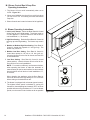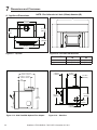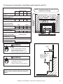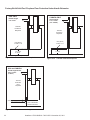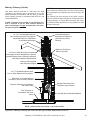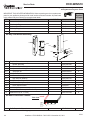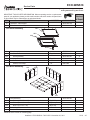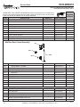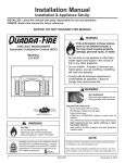
1
Owner’s Manual Installation and Operation Model: ECO-WINS18 WOOD BURNING INSERT CAUTION DO NOT DISCARD THIS MANUAL • Important operating and maintenance instructions included. • Read, understand and follow these instructions for safe installation and operation. WARNING If the information in these instructions is not followed exactly, a fire may result causing property damage, personal injury, or death. • Do not store or use gasoline or other flammable vapors and liquids in the vicinity of this or any other appliance. • Do not overfire - If heater or chimney connector glows, you are overfiring. Overfiring will void your warranty. • Comply with all minimum clearances to combustibles as specified. Failure to comply may cause house fire. • Leave this manual with party responsible for use and operation. WARNING HOT SURFACES! Glass and other surfaces are hot during operation AND cool down. Hot glass will cause burns. • Do not touch glass until it is cooled • NEVER allow children to touch glass • Keep children away • CAREFULLY SUPERVISE children in same room as fireplace. • Alert children and adults to hazards of high temperatures. High temperatures may ignite clothing or other flammable materials. • Keep clothing, furniture, draperies and other flammable materials away. WARNING Fire Risk. For use with solid wood fuel only. Other fuels may overfire and generate poisonous gases (i.e. carbon monoxide). Installation and service of this appliance should be performed by qualified personnel. Hearth & Home Technologies recommends NFI certified professionals, or technicians supervised by an NFI certified professional. www.heatilatorecochoice.com Consumer Care 1-877-427-3316 - Prior to calling, please have the model and serial number of the unit you are calling about. This information can be found at the front of the unit. 7065-132D • November 22, 2011 Read this manual before installing or operating this appliance. Please retain this owner’s manual for future reference. Congratulations! Congratulations on selecting a Heatilator wood burning appliance. The wood burning appliance you have selected is designed to provide the utmost in safety, reliability and efficiency. As the owner of a new wood burning appliance, you’ll want to read and carefully follow all of the instructions contained in this owner’s manual. Pay special attention to all cautions and warnings. This owner’s manual should be retained for future reference. We suggest you keep it with your other important documents and product manuals. Your new wood burning appliance will give you years of durable use and trouble-free enjoyment. Welcome to the Heatilator family of wood burning products! NOTE: Clearances may only be reduced by means approved by the regulatory authority having jurisdiction SAMPLE OF SERIAL NUMBER / SAFETY LABEL LOCATION: UNDER ASH LIP, PULL OUT TO VIEW HOT WHILE IN OPERATION DO NOT TOUCH, KEEP CHILDREN, CLOTHING AND FURNITURE AWAY. CONTACT MAY CAUSE SKIN CAUTION: BURNS. SEE NAMEPLATE AND INSTRUCTIONS. CHAUD LORS DE L'OPÉRATION. NE PAS TOUCHER. GARDEZ LES ENFANTS ET LES VÊTEMENTS LOIN DE L'ESPACE DÉSIGNÉ DE ATTENTION: L'INSTALLATION. LE CONTACT PEUT CAUSER DES BRÛLURES À LA PEAU. VOIR L'ÉTIQUETTE ET LES INSTRUCTIONS. Test Lab & Report Number ETL4001508 Model / Modèle: W/N 20514 LISTED ROOM HEATER, SOLID FUEL TYPE. "For Use with Solid Wood Fuel Only." Also For Use In Mobile Homes M Maximum Mantel Depth - 11.5" (292mm) Profondeur Maximum de la Manteau de Cheminée - 11.5" (292mm) Mantel / Manteau de Cheminée B S A Fascia or Trim / Panneau ou Moulure C A D Fuel Door F E Model Name ATTENTION! Inspectez et nettoyez la cheminée fréquemment. Sous certaines conditions, il se peut que la créosote s'accumule rapidement. Ne pas connecter cet appareil à une cheminée servant un autre appareil. DANGER: Il y a risque de décharge électrique. Déconnectez le fil électrique de la prise de contact avant le service. Éloignez le fil électrique de l'appareil. Ne pas faire passer le fil électrique au dessus ou en dessous de l'appareil. Puissance Électrique: 115 VAC, .63 Amps, 60 Hz. N'élevez pas le feu. Bâtissez le feu de bois directement sur l'âtre. Ne pas surchauffer. Si l'appareil de chauffage ou le tuyau de cheminée rougissent, vous surchauffez. Opérez l'appareil seulement lorsque la porte de chargement est fermée. Ouvrez la porte seulement lorsque vous devez ajouter des combustibles dans le feu. Remplacez la vitre seulement avec une vitre céramique de 5 mm disponible chez votre fournisseur. PIÈCES OPTIONNELLES: Déflecteur de cheminée d Piéce 7044-214 P operating instructions. CONTACT YOUR LOCAL BUILDING OR FIRE OFFICIALS ABOUT RESTRICTIONS AND INSTALLATION INSPECTION IN YOUR AREA. Refer to manufacturer's instructions and local codes for precautions required for passing chimney through a combustible wall or ceiling. When used as a masonry insert stove, install only in a masonry fireplace built to national and/or local codes. Do not remove brick or mortar to accommodate insert. Installation requires minimum of a starter pipe into existing chimney with airtight face seal. Install only on a non-combustible hearth. Approved for installation and use in factory built zero-clearance fireplaces conforming to minimum fire chamber specifications, follow instructions in the owner’s manual. Components required for installation: listed vent liner only. In Canada a full length 6 inch (152mm) S635 flue liner is required as per ULC S628-93. WARNING - Inspect and clean chimney frequently. Under certain conditions of use, creosote buildup may occur rapidly. Do not connect this unit to a chimney serving another appliance. DANGER: Risk of electrical shock. Disconnect power supply before servicing. Route power cord away from unit. Do not route cord under or in front of appliance. Electrical Rating: 115 VAC .63 AMPS 60 Hz Do not use grate or elevate fire. Build wood fire directly on hearth(firebrick). Do not overfire. If heater or chimney connector glows, you are overfiring. Operate only with doors closed. Open only to add fuel to the fire. Replace glass only with 5mm ceramic available from your dealer. OPTIONAL COMPONENTS: Mantel Deflector, Part MNTL-18-DFLCTR Serial Number PRÉVENTION DES FEUX DE MAISON E Install and use only in accordance with manufacturer's installation, venting and APPAREIL DE CHAUFFAGE DE PIÈCE, DE TYPE DE COMBUSTIBLE SOLIDE. Installez et utilisez en accord avec les instructions d'installation et d'opération du fabricant. Contactez le bureau de la construction ou le bureau des incendies au sujet des restrictions et des inspections d'installation dans votre voisinage. Référez vous aux instructions du fabricant et des codes locaux pour les précautions requises pour passer une cheminée à travers un mur ou un plafond combustibles, et les compensations maximums. Lorsque vous utilisez un poêle inséré fabriqué en briques, installez un foyer en briques fabriqué selon des codes national et/ou locaux. Ne pas enlever de la brique ou du mortier pour accommoder la pièce insérée. L'installation demande un tuyau allant de la cheminée existante avec un couvert hermétique. Installez seulement sur un foyer incombustible. Approuvé pour l'installation et l'usage dans les cheminées avec espace libre de zéro, fabriquées en usine et se conformant aux spécifications minimum de chambre de feu. Composants requis pour l'installation: aération homologué revêtement seulement. Au Canada, un tuyau doublé de grandeur de 6 inch (152mm) S635 est exigé par le code ULC S628-93. L PREVENT HOUSE FIRES SideWall / Mur de Côté Serial No / Numéro De Série 007026 ECO-WINS18 WOOD INSERT Tested to / Testé a: UL 1482, ULC S628-93 Minimum Clearances To Combustible Material Espaces Libres Minimum Des Matériaux Combustibles Masonry, Heat Exchanger & Zero Clearance En briques, Circulant la chaleur & d'espace libre MANTEL CLEARANCES Espace Libre Manteau de Cheminée No Mantel Deflector Pas de protection de cheminée with Mantel Deflector avec un déflecteur de cheminée USA/États-Unis A 18” (457) n/a B n/a A 18” (457) C D n/a 18” (457) 18" 26" (660) (457) n/a 21.25” 18” n/a (540) (457) n/a FLOOR PROTECTION / PROTECTION DU PLANCHER Floor height 0" to 7" (0 to 178mm) below Insert Base Hauteur du sol de 0” à 7” (0 à 178mm) sous la base de l’insert Floor height greater than 7" (178mm) below Insert Base Hauteur de sol supérieure à 7” (178mm) sous la base de l’insert B n/a CANADA D 18" (457) n/a 26" (660) 18" (457) n/a n/a 21.25” (540) 18” (457) n/a CANADA USA/États-Unis F 8" (203) 8” (203) E 16" (406) 16" (406) C n/a E 18" (457) 18" (457) THERMAL PROTECTION / Protection Thermique Floor height 0" to 7" (0 to-178mm) below Insert Base Hauteur du sol de 0” à 7” (0 à 178mm) sous la base de l’insert 1 inch (25) of k=0.47, R = 2.13 Floor height greater than 7" (178) below Insert Base Hauteur de sol supérieure à 7” (178) sous la base de l’insert Only ember protection required F 12" (305) 12” (305) USA/États-Unis & Canada Hearth Extension / Extension de l'âtre Manufactured by / Fabriqué par: U.S. ENVIRONMENTAL PROTECTION AGENCY - Certified to comply with July 1990 particulate emission standards. 2011 2012 2013 JAN FEB MAR APR MAY JUN JUL AUG SEP OCT NOV DEC 1445 N. Highway, Colville, WA 99114 www.heatilatorecochoice.com 2 Made in U.S.A. of US and imported parts. Fabriqué aux États-Unis-d’Amérique par des pièces d’origine américaine et pièces importées. DO NOT REMOVE THIS LABEL / NE PAS ENLEVER L'ÉTIQUETTE Heatilator • ECO-WINS18 • 7065-132D • November 22, 2011 7065-134 Mfg Date ! Safety Alert Key: • DANGER! Indicates a hazardous situation which, if not avoided will result in death or serious injury. • WARNING! Indicates a hazardous situation which, if not avoided may result in death or serious injury. • CAUTION! Indicates a hazardous situation which, if not avoided, may result in minor or moderate injury. • NOTICE: Indicates practices which may cause damage to the appliance or to property. TABLE OF CONTENTS Congratulations ...............................................................2 Sample of Safety/Serial Number Label ...........................2 Warranty Policy ...............................................................4-5 Section 1: Listing and Code Approvals A. B. C. D. Appliance Certifications.....................................6 Mobile Home Approved.....................................6 Glass Specifications ..........................................6 BTU & Efficiency Specifications ........................6 User’s Guide Section 2: Operating Instructions A. B. C. D. E. F. G. H. I. J. K. L. M. N. O. P. Q. R. Your Wood Appliance .......................................7 Fire Safety .........................................................8 Overfiring...........................................................8 Combustible/Non-combustible Material ............8 Seasoned Wood................................................8 Chimney Fire .....................................................8 Burning Process ................................................9 Burn Rate Air Control ........................................10 Burn Rates and Operating Efficiency ................10 Correct Baffle & Blanket Placement ..................11 Building a Fire ...................................................12 Wood Fuel & Storage ........................................13 Blower Control Box Snap Disc Operations .......14 Blower Operating Instructions ...........................14 Clear Space ......................................................15 Frequently Asked Questions .............................15 Opacity (Smoke) ...............................................15 Quick Start Guide ..............................................16 Section 3: Maintenance and Service A. B. C. D. E. F. Disposal of Ashes .............................................17 Chimney & Chimney Connector Inspection/Cleaning...........................................17 Appliance Inspection - Routine .........................17 Glass Cleaning ..................................................18 Firebrick Inspection & Replacement Instruction 18 Quick Reference Maintenance Guide ...............19 Section 4: Troubleshooting Guide ..................... 21 Section 5: Service Parts Replacement A. B. C. D. E. F. G. Glass Replacement ...........................................21 Snap Disc Replacement....................................21 Wiring Diagram .................................................21 Blower Replacement .........................................22 Baffle & Ceramic Blanket Removal ...................23 Door Handle Assembly .....................................23 Tube Channel Assembly Replacement .............24 Installer’s Guide Section 6: Getting Started A. B. C. D. E. F. G. H. I. Design, Installation & Location Considerations ..................................................25 Draft ..................................................................25 Negative Pressure.............................................26 Locating Your Appliance and Chimney .............27 Chimney Termination Requirements.................27 2-10-3 Rule .......................................................28 Tools and Supplies Needed ..............................29 Fire Safety .........................................................29 Inspect Appliance and Components and Pre-Burn Checklist .....................................29 Section 7: Dimensions and Clearances A. B. C. Appliance Dimensions.......................................30 Clearances to Combustibles (UL and ULC) and Hearth Protection Requirements ................31-32 Alternate Floor Protection Calculation...............33 Section 8: Chimney Systems A. B. C. D. E. F. G. H. I. J. K. Venting Systems ...............................................34 Inspections ........................................................34 Larger Chimneys ...............................................34 Masonry Chimney .............................................34-35 Metal Heat Circulating Chimney........................36 Prefabricated Metal Chimney ............................36 Securing Chimney Components .......................37 Altering the Fireplace ........................................37 Factory-Built Solid Fuel Fireplaces ...................37 Ovalizing Round Stainless Steel Liners ............38 Chimney Height / Rise and Run ........................38 Section 9: Appliance Set-up A. B. C. D. E. Outside Air Kit Installation .................................39 Securing Stove Pipe/Liner to Flue Collar ..........40 Optional Offset Adapter Installation ..................40 Securing Appliance to Stove Pipe/Liner ............41 Standard Surround & Cast Trim, .......................41 Section 10: Moble Home Installation ................. 42 Section 11: Reference Materials Service Parts & Accessories .....................................43-46 Service Maintenance Log..........................................47 Contact Information ...................................................48 Heatilator • ECO-WINS18 • 7065-132D • November 22, 2011 3 Hearth & Home Technologies Inc. HEATILATOR ECO-CHOICE WARRANTY Hearth & Home Technologies Inc., on behalf of its hearth brands (“HHT”), extends the following warranty for ECOCHOICE by heatilator wood and pellet hearth appliances that are purchased from an HHT authorized dealer. WARRANTY COVERAGE: HHT warrantes to the original owner of the HHT appliance at the site of installation, and to any transferree taking ownership of the appliance at the site of installation within two years following the date of original purchase, that the HHT appliance will be free from defects in materials and workmanship at the time of manufacture. After installation, if covered components manufactured by HHT are found to be defective in materials or workmanship during the applicable warranty period, HHT will, at its option, repair or replace the covered components. HHT, at its own discretion, may fully discharge all of its obligations under such warranties by replacing the product itself or refunding the verified purchase price of the product itself. The maximum amount recoverable under this warranty is limited to the purchaser price of the product. This warranty is subject to conditions, exclusions and limitations as described below. WARRANTY PERIOD: Warranty coverage begins on the date of original purchase. In the case of new home construction, warranty coverage begins on the date of first occupancy of the dwelling or six months after the sale of the product by an independent, authorized HHT dealer/distributor, whichever occurs earlier. The warranty shall commence no later than 24 months following the date of product shipment from HHT, regardless of the installation or occupancy date. The warranty period for parts and labor for covered components is produced in the following table. Warranty Period Parts Labor Heatilator ECO-CHOICE Appliances Pellet EPA Wood 1 year X X 3 years X 3 years 1 year 5 years 3 years 5 years 3 years 90 days X Components Covered All parts and material except as covered by Conditions, Exclusions, and Limitations listed Firepots and burnpots X Castings X Manifold tubes X X Firebox and heat exchanger X X All replacement parts beyond warranty period See conditions, exclusions,and limitations on next page 7014-212B 4 Page 1 of 2 1-10-11 Heatilator • ECO-WINS18 • 7065-132D • November 22, 2011 WARRANTY COVERAGE: • • • • This warranty only covers HHT appliances that are purchased through an HHT authorized dealer or distributor. A list of HHT authorized dealers is available on th HHT branded websites. This warranty is only valid while the HHT appliance remains at the site of original installation. Contact your installing dealer for warranty service. If the installing dealer is unable to provide necessary parts, contact the nearest HHT authorized dealer or supplier. Additional service fees may apply if you are seeking warranty service from a dealer other than the dealer from whom you originally purchased the product. Check with your dealer in advance for any costs to you when arranging a warranty call. Travel and shipping charges for parts are not covered by this warranty. WARRANTY EXCLUSIONS: This warranty does not cover the following: • Changes in surface finishes as a result of normal use. As a heating appliance, some changes in color of interior and exterior surface finishes may occur. This is not a flaw and is not covered under warranty. • Damage to printed, plated, or enameled surfaces caused by fingerprints, accidents, misuse, scratches, melted items, or other external sources and residues left on the plated surfaces from the use of abrasive cleaners or polishes. • Repair or replacment of parts that are subject to normal wear and tear during the warranty period. These parts include: paint, wood, pellet and coal gaskets; firebricks; grates; flame guides; light bulbs; batteries and the discoloration of glass. • Minor expansion, contraction, or movement of certain parts causing noise. These conditions are normal and complaints related to this noise are not covered by this warranty. • Damages resulting from: (1) failure to install, operate, or maintain the appliance in accordance with the installation instructions, operating instructions, and listing agent identification label furnished with the appliance; (2) failure to install the appliance in accordance with local building codes; (3) shipping or improper handling; (4) improper operation, abuse, misuse, continued operation with damaged, corroded or failed components, accident, or improperly/incorrectly performed repairs; (5) environmental conditions, inadequate ventilation, negative pressure, or drafting caused by tightly sealed constructions, insufficient make-up air supply, or handling devices such as exhaust fans or forced air furnaces or other such causes; (6) use of fuels other than those specified in the operating instructions; (7) installation or use of components not supplied with the appliance or any other components not expressly authorized and approved by HHT; (8) modification of the appliance not expressly authorized and approved by HHT in writing; and/or (9) interruptions or fluctuations of electrical power supply to the appliance. • Non-HHT venting components, hearth components or other accessories used in conjunction with the appliance. • Any part of a pre-existing fireplace system in which an insert or a decorative gas appliance is installed. • HHT’s obligation under this warranty does not extend to the appliances’ capability to heat the desired space. Information is provided to assist the consumer and the dealer in selecting the proper appliance for the application. Consideration must be given to appliance location and configuration, environmental conditions, insulation and air tightness of the structure. This warranty is void if: • • • The appliance has been over-fired or operated in atmospheres contaminated by chlorine, fluorine, or other damaging chemicals. Overfiring can be identified by, but not limited to, warped plates or tubes, rust colored cast iron, bubbling, cracking and discoloration of steel or enamel finishes. The appliance is subjected to prolonged periods of dampness or condensation. There is any damage to the appliance or other components due to water or weather damage which is the result of, but not limited to improper chimney or venting installation. WARRANTY EXCLUSIONS: • The owner’s exclusive remedy and HHT’s sole obligation under this warranty, under any other warranty, express or implied, or in contract, tort or otherwise, shall be limited to replacement, repair, or refund, as specified above. In no event will HHT be liable for any incidiental or consequential damages caused by defects in the appliance. Some states do not allow exclusions or limitation of incidental or consequential damages, so these limitations may not apply to you. This warranty gives you specifice rights; you may also have other rights, which vary from state to state. EXCEPT TO THE EXTENT PROVIDED BY LAW, HHT MAKES NO EXPRESS WARRANTIES OTHER THAN THE WARRANTY SPECIFIED HEREIN. THE DURATION OF ANY IMPLIED WARRANTY IS LIMITED TO DURATION OF THE EXPRESSED WARRANTY SPECIFIED ABOVE. 7014-212B Page 2 of 2 1-10-11 Heatilator • ECO-WINS18 • 7065-132D • November 22, 2011 5 1 Listing and Code Approvals A. Appliance Certification D. BTU & Efficiency Specifications Model: ECO-WINS18 EPA Certified: 2.6 grams per hour Laboratory: Intertek Efficiency: 88% Report No: 100398890PRT-001 BTU Output: 10,900 to 22,600 / hr Type: Solid Fuel Type, Listed Room Heater Heating Capacity: Standard: UL1482 and ULC S628-93 and (UM) 84-HUD, Mobile Home Approved. 1,130 to 2,060 sq ft depending on climate zone Vent Size: 6 inches Firebox Size: 2.0 cubic feet Max Wood Length: 18 inches Fuel: Cord Wood Shipping Weight: 337 lbs NOTE: This installation must conform with local codes. In the absence of local codes you must comply with the UL1482, (UM) 84-HUD and NPFA211 in the U.S.A. and the ULC S62893 and CAN/CSA-B365 Installation Codes in Canada. WARNING The Heatilatro ECO-WINS18 meets the U.S. Environmental Protection Agency’s 1990 particulate emission standards. Intertek Testing Laboratory is a National Recognized Test Lab (NRTL) approved by OSHA. B. Mobile Home Approved • This appliance is approved for mobile home installations when not installed in a sleeping room and when an outside combustion air inlet is provided. • The structural integrity of the mobile home floor, ceiling, and walls must be maintained. • The appliance must be properly grounded to the frame of the mobile home with #8 copper ground wire, and use only listed double-wall connector pipe. • Outside Air Kit, part OAK-ACC must be installed in a mobile home installation. C. Glass Specifications This stove is equipped with 5mm ceramic glass. Replace glass only with 5mm ceramic glass. Please contact your dealer for replacement glass. Fire Risk. • • • • • • • Hearth & Home Technologies disclaims any responsibility for, and the warranty will be voided by, the following actions: Installation and use of any damaged appliance. Modification of the appliance. Installation other than as instructed by Hearth & Home Technologies. Installation and/or use of any component part not approved by Hearth & Home Technologies. Operating appliance without fully assembling all components. Operating appliance without legs attached (if supplied with unit). Do NOT Overfire - If appliance or chimney connector glows, you are overfiring. Any such action that may cause a fire hazard. Improper installation, adjustment, alteration, service or maintenance can cause injury or property damage. For assistance or additional information, consult a qualified installer, service agency or your dealer. NOTE: Hearth & Home Technologies, manufacturer of this appliance, reserves the right to alter its products, their specifications and/or price without notice. ECO-CHOICE is a registered trademark of Hearth & Home Technologies. 6 Heatilator • ECO-WINS18 • 7065-132D • November 22, 2011 2 User Guide Operating Instructions WARNING HOT SURFACES! Glass and other surfaces are hot during operation AND cool down. Hot glass will cause burns. • DO NOT touch glass until it is cooled • NEVER allow children to touch glass • Keep children away • CAREFULLY SUPERVISE children in same room as appliance. • Alert children and adults to hazards of high temperatures. High temperatures may ignite clothing or other flammable materials. • Keep clothing, furniture, draperies and other flammable materials away. NOTICE: If you expect that children may come into contact with this appliance, we recommend a barrier such as a decorative screen. See your dealer for suggestions. A. Your Wood Appliance WARNING! DO NOT operate appliance before reading and understanding operating instructions. Failure to operate appliance according to operating instructions could cause fire or injury. SURROUND & TRIM SET BURN RATE CONTROL DOOR HANDLE SERIAL LABEL POWER CORD BLOWER CONTROL PANEL Figure 7.1 General Operating Parts Heatilator • ECO-WINS18 • 7065-132D • November 22, 2011 7 B. Fire Safety D. Combustible/Non-combustible Materials To provide reasonable fire safety, the following should be given serious consideration: • 1. Install at least one smoke detector on each floor of your home to ensure your safety. They should be located away from the heating appliance and close to the sleeping areas. Follow the smoke detector manufacturer’s placement and installation instructions, and be sure to maintain regularly. 2. A conveniently located Class A fire extinguisher. 3. A practiced evacuation plan, consisting of at least two escape routes. 4. In the event of a chimney fire: a. b. Non-combustible Material Material which will not ignite and burn. Such materials are those consisting entirely of steel, iron, brick, tile, slate, glass or plasters, or any combination thereof. • Non-combustible Sealant Material Sealants which will not ignite and burn: Rutland, Inc. Fireplace Mortar #63, Rutland 76R, Nuflex 304, GE RTV106 or GE RTB116 (or equivalent). Burn only dry seasoned wood. Do not over-fire. Over-firing may ignite creosote or will damage the stove and chimney. To prevent over-firing your stove, DO NOT: • Use flammable liquids • Overload with wood • Burn trash or large amounts of scrap lumber • Permit too much air to the fire 1. Symptoms of Over-Firing Symptoms of over-firing may include one or more of the following: Chimney connector or appliance glowing Roaring, rumbling noises Loud cracking or banging sounds Metal warping Chimney fire 2. What To Do if Your Stove is Over-Firing • Immediately close the door and air controls to reduce air supply to the fire. • If you suspect a chimney fire, call the fire department and evacuate your house. • Contact your local chimney professional and have your stove and stove pipe inspected for any damage. • Do not use your stove until the chimney professional informs you it is safe to do so. Hearth & Home Technologies WILL NOT warranty stoves that exhibit evidence of over-firing. Evidence of over-firing includes, but is not limited to: • Warped air tube • Deteriorated refractory brick retainers • Deteriorated baffle and other interior components 8 • E. Seasoned Wood WARNING! Risk of Fire! • • • • • Material made of or surfaced with wood, compressed paper, plant fibers, plastics, or any material capable of igniting and burning, whether flame-proofed or not, plastered or unplastered. Prepare occupants for immediate evacuation Notify fire department C. Overfiring Combustible Material • Store wood under cover, out of the rain and snow. • Dry and well-seasoned wood will not only minimize the chance of creosote formation, but will give you the most efficient fire. • Even dry wood contains at least 15% moisture by weight, and should be burned hot enough to keep the chimney hot for as long as it takes to dry the wood out - about one hour. • It is a waste of energy to burn unseasoned wood of any kind. Dead wood lying on the forest floor should be considered wet, and requires full seasoning time. • Standing dead wood can be considered to be about 2/3 seasoned. • To tell if wood is dry enough to burn, check the ends of the logs. • If there are cracks radiating in all directions from the center, it is dry. • If your wood sizzles in the fire, even though the surface is dry, it may not be fully cured. F. Chimney Fire WARNING! Risk of Fire! A chimney fire can permanently damage your chimney system and nearby structures. In the event of a chimney fire, Hearth & Home Technologies Inc. recommends • Replacement of the chimney, and • Inspection of the adjacent structure to the provisions of NFPA Level III inspection criteria Heatilator • ECO-WINS18 • 7065-132D • November 22, 2011 G. Burning Process 2. Second Stage In recent years there has been an increasing concern about air quality. Much of the blame for poor air quality has been placed on the burning of wood for home heating. In the secondary stage wood gives off flammable gases which burn above the fuel with bright flames. In order to improve the situation, we have developed cleanerburning wood appliances that surpass the requirements for emissions established by our governing agencies. • The flames must be maintained and not allowed to go out to ensure the cleanest possible fire. These wood appliances must be properly operated in order to ensure that they perform the way they are designed to perform. NOTICE: Improper operation can turn any wood appliance into a smoldering environmental hazard. 1. Kindling or First Stage It helps to know a little about the actual process of burning in order to understand what goes on inside the appliance. The first stage of burning is called the kindling stage. In this stage: During this stage of burning: • If the flames tend to go out, it is set too low for your burning conditions. The air control located at the upper right hand corner is used to adjust for burn rates. This is called the Burn Rate Air Control. Figure 10.1 on page 10. 3. Final Stage The final stage of burning is the charcoal stage. This occurs when the flammable gases have been mostly burned and only charcoal remains. This is a naturally clean portion of the burn. The coals burn with hot blue flames. • It is very important to reload your appliance while enough lively hot coals remain in order to provide the amount of heat needed to dry and rekindle the next load of wood. • Wood is heated to a temperature high enough to evaporate the moisture present in all wood. • It is best to open the Burn Rate Air Control before reloading. This livens up the coalbed and reduces excessive emissions (opacity/smoke). Figure 10.1 on page 10. • Wood will reach the boiling point of water (212°F) and will not get any hotter until the water is evaporated. • Open door slowly so that ash or smoke does not exit appliance through opening. This process takes heat from the coals and tends to cool the appliance. • Break up any large chunks and distribute the coals so that the new wood is laid on hot coals. Fire requires three things to burn: • Fuel • Air • Heat If heat is robbed from the appliance during the drying stage, the new load of wood has reduced the chances for a good clean burn. Air quality is important to all of us, and if we choose to use wood to heat our homes we should do so responsibly. We need to learn to burn in the cleanest way possible allowing us to continue using our wood appliances for many years to come. It is always best to burn dry, seasoned firewood. When the wood isn’t dry, you must open the air controls and burn at a high burn setting for a longer time to start it burning. The heat generated from the fire should be warming your home and establishing the flue draft, not evaporating the moisture out of wet, unseasoned wood, resulting in wasted heat. Heatilator • ECO-WINS18 • 7065-132D • November 22, 2011 9 H. Burn Rate Air Control • The air supply enters at the upper front of the firebox, near the top of the glass door. • This preheated air supplies the necessary fresh oxygen to mix with the unburned gases, helping to create second, third and fourth combustions • This air is regulated by the Burn Rate Air Control. • There are four settings High, Medium-High, Medium-Low and Low. • When the control is raised all the way up it is on the High setting and when pushed all the down it is on the Low setting. Figure 10.1. I. Burn Rates and Operating Efficiency For maximum operating efficiency 1. Follow the instructions below for each burn rate for the Burn Rate Air Control. Figure 10.1. 2. Burn dry, well-seasoned wood. Burn Rates 1. Starting a Fire • Open the Burn Rate Air Control by raising it all the way to the top for the High setting. • The blower tends to cool the appliance. Leave the blower off until the burn is well established, i.e., 30 minutes. • After loading the appliance with wood and starting the fire, set the Burn Rate Air Controls to the desired setting by following the burn rate instructions below. 2. High Burn Rate - Maximum Heat* - 30,000+ BTU/hr • Raise the Burn Rate Air Control all the way up until it stops (top marker) to a fully open position. • Be sure and monitor the fire closely while in this setting to avoid overfiring your stove. -HIGH -MEDIUM HIGH -MEDIUM -LOW 3. Medium-High Burn Rate* - 15,000 to 30,000 BTU/hr • Raise the Burn Rate Air Control to the Medium High marker. Blower may remain on. 4. Medium-Low Burn Rate* - 10,000 to 15,000 BTU/hr • Raise the Burn Rate Air Control to the Medium marker. Leave the blower off until the burn is well established, i.e., 30 minutes. 5. Low Burn Rate* - Below 10,000 BTU/hr • Leave the Burn Rate Air Control at the bottom marker. Leave the blower off until the burn is well established, i.e., 30 minutes. *NOTE: These are approximate settings, and will vary with type of wood or chimney draft. Due to altitude and other environmental circumstances, this operational information is a guideline only. Figure 10.1 - Burn Rate Air Control 10 Heatilator • ECO-WINS18 • 7065-132D • November 22, 2011 J. Correct Baffle & Blanket Placement INCORRECT POSITIONS WARNING Fire Risk Improper baffle placement may cause: • Overheating of firebox • Overheating the chimney Baffle must be placed properly (see instructions) Replace baffle if damaged or missing. NOTE: A missing, damaged or improperly positioned baffle is dangerous and may cause damage and poor efficiency. It will also void your warranty. Ceramic Blanket and Baffle Board are NOT in contact with the back of the firebox. Note: This are generic drawings and may not represent your specific model. CORRECT POSITION Ceramic Blanket Back of Firebox Ceramic Blanket is NOT in contact with the back of the firebox and NOT even with the Baffle Board in the front. Ceramic Blanket Back of Firebox Baffle Board Ceramic Blanket and Baffle Board MUST be in contact with the back of the firebox and even with each other in the front. Figure 12.1 - Correct Baffle and Blanket Positions Baffle Board Ceramic Blanket is bunched up at the back of the firebox and NOT even with the Baffle Board in the front. Figure 12.2 - Incorrect Baffle and Blanket Positions Heatilator • ECO-WINS18 • 7065-132D • November 22, 2011 11 K. Building A Fire WARNING Fire Risk. Keep combustible materials, gasoline and other flammable vapors and liquids clear of appliance. • Do NOT store flammable materials in the appliance’s vicinity. • DO NOT USE GASOLINE, LANTERN FUEL, KEROSENE, CHARCOAL LIGHTER FLUID OR SIMILAR LIQUIDS TO START OR “FRESHEN UP” A FIRE IN THIS HEATER. • Keep all such liquids well away from the heater while it is in use. • Combustible materials may ignite. Before lighting your first fire in the appliance: 1. Confirm the baffle and ceramic blanket are correctly positioned. See page 11 for detailed diagrams. They should be even with the front tube and resting on both tubes. Figure 12.1. 2. Remove all labels from glass. There are many ways to build a fire. The basic principle is to light easily-ignitable tinder or paper, which ignites the fast burning kindling, which in turn ignites the slow-burning firewood. Here is one method that works well: 9. When ready to reload, It is best to set the Burn Rate Air Control in the High position before reloading. • This livens up the coalbed and reduces excessive emissions (opacity/smoke). • Open door slowly so that ash or smoke does not exit appliance through opening. • Large logs burn slowly, holding a fire longer. • Small logs burn fast and hot, giving quick heat. 10. As long as there are hot coals, repeating steps 6 through 8 will maintain a continuous fire throughout the season. NOTE: • Build fire on brick firebox floor only. • Do NOT use grates or other methods to support fuel. It will adversely affect emissions. CAUTION Odors and vapors released during initial operation. • Curing of high temperature paint. • Open windows for air circulation. Odors may be irritating to sensitive individuals. 1. Raise the Burn Rate Air Control to the High Setting. 2. Place several wads of crushed paper on the firebox floor. Heating the flue with slightly crumpled newspaper before adding kindling keeps smoke to a minimum. 3. Lay small dry sticks of kindling on top of the paper. 4. Make sure that no matches or other combustibles are in the immediate area of the appliance. Be sure the room is ventilated and the flue unobstructed. 5. Light the paper in the appliance. NEVER light or rekindle fire with kerosene, gasoline, or charcoal lighter fluid; the results can be fatal. 6. Once the kindling is burning quickly, add several full-length logs 3 to 4 inches (76 to 102mm) in diameter. Be careful not to smother the fire. Stack the pieces of wood 1/2 inch to 1 inch apart; near enough to keep each other hot, but far enough away from each other to allow air flow between them. 7. Once there is an established bed of coals, set the Burn Rate Air Control to the desired setting following the instructions found in the Section: Burn Rates and Operating Efficiency. 8. If you have installed the optional blower, please note that the blower tends to cool the appliance. Leave the blower off until the burn is well established, i.e., 30 minutes. 12 Heatilator • ECO-WINS18 • 7065-132D • November 22, 2011 Moisture L. Wood Fuel & Storage WARNING Fire Risk. • DO NOT BURN GARBAGE OR FLAMMABLE FLUIDS SUCH AS GASOLINE, NAPTHA OR ENGINE OIL. The majority of the problems appliance owners experience are caused by trying to burn wet, unseasoned wood. • Wet, unseasoned wood requires energy to evaporate the water instead of heating your home, and • Causes evaporating moisture which cools your chimney, accelerating formation of creosote. • DO NOT USE CHEMICALS OR FLUIDS TO START A FIRE. • Do NOT burn treated wood or wood with salt (driftwood). • May generate carbon monooxide if burn material other than wood. May result in illness or possible death. WARNING Fire Risk. • Do NOT burn wet or green wood. • Store wood in dry location. • Stack wood so both ends are exposed to air. Wet, unseasoned wood can cause accumulation of creosote. Hardwood vs Softwood Seasoned Wood Your appliance performance depends on the quality of the firewood you use. • Cut logs to size • Seasoned wood contains about 8,000 BTUs per pound . • Split to 6 inches (152 mm) or less in diameter • Hard woods are more dense than soft woods. • Air dry to a moisture content of not more than 20% • Hard woods contain 60% more BTUs than soft woods. - Soft wood - about nine months to dry • Hard woods require more time to season, burn slower and are harder to ignite. - Hard wood - about eighteen months to dry • Soft woods require less time to dry, burn faster and are easier to ignite. • Start the fire with softwood to bring the appliance up to operating temperature and to establish draft. • Add hardwood for slow, even heat and longer burn time. NOTICE: Seasoning time may vary depending on drying conditions. Storing Wood Steps to ensure properly seasoned wood: Soft woods Hard woods • • • • • • • • • • • Douglas Fir Pine Spruce Cedar Oak Maple Apple Birch Poplar Aspen Alder Processed Solid Fuel Fire Logs • • Stack wood to allow air to circulate freely around and through woodpile. • Elevate wood pile off ground to allow air circulation underneath. • Smaller pieces of wood dry faster. Any piece over 6 in. (152 mm) in diameter should be split. • Wood (whole or split) should be stacked so both ends of each piece are exposed to air. More drying occurs through the cut ends than the sides. • Store wood under cover to prevent water absorption from rain or snow. Avoid covering the sides and ends completely. NOT permitted for use in this appliance WARNING Fire Risk Do NOT store wood: • In front of the appliance. • In space required for loading or ash removal. Heatilator • ECO-WINS18 • 7065-132D • November 22, 2011 13 M. Blower Control Box & Snap Disc Operating Instructions 1. The blower will turn on/off automatically when set to AUTO. Figure 14.1. 2. When set to MANUAL, the fan will turn on/off only when you turn it on or off. This setting over-rides the internal snap disc. 3. Blower Controls are located on bottom left of appliance. N. Blower Operating Instructions 1. Initial (cold) startup: Raise the Burn Rate Air Control all the way up to the High setting. The blower tends to cool the appliance. Leave the blower off until the burn is well established, i.e., 30 minutes. 2. High Burn Setting: Raise the Burn Rate Air Control all the way up to the High setting. The blower may remain on. 3. Medium or Medium High Burn Setting: Burn Rate Air Control is closed then opened to 1 inch (pull up). The blower may remain on. 4. Medium Low Burn Setting: Burn Rate Air Control is closed then opened to 1/4 inch to 1/2 inch (pull up). Leave the blower off for the first 30 minutes until the burn is well established. 5. Low Burn Setting: Burn Rate Air Control is closed (down position). Leave the blower off for the first 30 minutes until the burn is well established. NOTE: For maximum efficiency and lowest emissions, when operating the blower in either the automatic or manual setting for the low and medium low burn settings leave the blower off until the burn is well established, i.e., 30 minutes, When reloading the appliance, raise the Burn Rate Air Control all the wall to the High setting for 5 to 15 minutes before setting to the desired burn rate. 6. The blower is equipped with a rheostat (speed control). The highest blower speed is obtained by turning the rheostat on, then adjusting back towards “OFF” as far as possible without turning the blower off. For a low blower speed, turn the control knob clockwise as far as possible Figure 14.1 14 Heatilator • ECO-WINS18 • 7065-132D • November 22, 2011 O. Clear Space Q. Opacity (Smoke) • Opacity is the measure of how cleanly your appliance is burning. Do NOT place combustible objects within 4 ft (1.2 m) of the front of fireplace. Figure 15.1. Opacity is measured in percent: • 100% opacity is when an object is totally obscured by the smoke column from a chimney, and WARNING Fire Risk. • • Do NOT place combustible objects within 48 inches in front of the appliance. High temperatures may ignite clothing, furniture or draperies. • 0% opacity means that no smoke column can be seen. As you become familiar with your appliance, you should periodically check the opacity. This will allow you to know how to burn as nearly smoke-free as possible (goal of 0% opacity). NOTICE! Do NOT operate a circulating fan within close proximity, approximately 4 ft (1.2m), of appliance • Can reverse air flow, blowing hot air into appliance cavity. • Can damage appliance blower due to overheating. Maintain 4 ft (1.22m) clearance to combustible in front of appliance Figure 15.1 - Clear Space P. Frequently Asked Questions ISSUES SOLUTIONS Odor from appliance When first operated, this appliance may release an odor for the first several hours. This is caused by the curing of the paint and the burning off of any oils remaining from manufacturing. Metallic noise Noise is caused by metal expanding and contracting as it heats up and cools down, similar to the sound produced by a furnace or heating duct. This noise does not affect the operation or longevity of the appliance. Whirring sound The blower may produce a whirring sound which increases in volume as the speed is increased. CAUTION Odors and vapors released during initial operation. • Curing of high temperature paint. • Open windows for air circulation. Odors may be irritating to sensitive individuals. Heatilator • ECO-WINS18 • 7065-132D • November 22, 2011 15 R. Quick Start Guide Note: This are generic drawings and may not represent your specific model. FIRST FIRE ITEMS NEEDED: OPEN AIR CONTROL 10 Pieces of Newspaper, 10-20 Pieces of Dry Kindling and a Few Pieces of Dry Split Wood. ADD NEWSPAPER LOAD WOOD HIGH LOW 3 2 1 ADD KINDLING WARNING! Risk of Fire Close and securely latch the door after the fire has started, and after refueling, to prevent: • Spillage of smoke, flame and carbon monoxide • Spillage of sparks, coals and logs • Over-firing DO NOT leave the stove unattended with the door open. LIGHT THE PAPER Starting a fire may not require an open door for draft. The air control should supply adequate draft. 5 4 ADD MORE WOOD REDUCE AIR CONTROL Set to desired heat output HIGH The stove is ready for normal operation. LOW 6 16 7 Heatilator • ECO-WINS18 • 7065-132D • November 22, 2011 3 Maintenance and Service A. Disposal of Ashes • • Frequency: When ash is within 1-3/4 inch (44mm) of firebox lip. Leave 1/4 to 1/2 inch (6-13mm) of ash in the bottom of the firebox. Creosote - Formation and Need for Removal • When wood is burned slowly, it produces tar and other organic vapors, which combine with expelled moisture to form creosote. • The creosote vapors condense in the relatively cool chimney flue of a slow-burning fire. • As a result, creosote residue accumulates on the flue lining. When ignited this creosote makes an extremely hot fire. • The chimney and chimney connector shall be inspected every two months during the heating season to determine when a creosote buildup has occurred. • When creosote has accumulated it shall be removed to reduce the risk of a chimney fire. By: Homeowner WARNING! Risk of Fire! Ashes could contain hot embers. • Place ashes in a metal container with a tight-fitting lid. • The closed container should be placed on a noncombustible floor or on the ground, well away from all combustible materials, pending final disposal. • If the ashes are disposed of by burial in soil or otherwise locally dispersed, they should be retained in the closed container until all cinders have thoroughly cooled C. Appliance Inspection - Routine B. Chimney and Chimney Connector Inspection/Cleaning • Frequency: Every 2 months at the same time the chimney and chimney connector are inspected. • Frequency: Every 2 months during heating season or as recommended by a certified chimney sweep; more frequently if chimney exceeds or is under 14-16 ft (4.34.8m). (measured from bottom of appliance). • By: Homeowner By: Certified Chimney Sweep • Door handle - smooth cam operation • Check for: • Cracks in glass • Baffle and ceramic blanket correct placement WARNING! Risk of Fire! Ignited creosote is extremely HOT. Prevent creosote buildup. • Remove all ash from the firebox and extinguish all hot embers before disposal. • Allow the appliance to cool completely. • Disconnect flue pipe or remove baffle and ceramic blanket from appliance before cleaning chimney. Otherwise residue can pile up on top of the baffle and ceramic blanket. (See Baffle Removal on page 23). • Close the door tightly. • The creosote or soot should be removed with a brush specifically designed for the type of chimney in use. • Clean out fallen ashes from the firebox. • It is also recommended that before each heating season the entire system be professionally inspected, cleaned and repaired if necessary. • Baffle for cracks • Firebrick for cracks, broken or crumbly • Door gasket. (Dollar bill test). Place a dollar bill between the stove and the door and then shut the door. If you can pull the dollar bill out, remove one spacing washer from the door handle behind the latch cam and try the test again. See Figure 22.1 on page 22. If you can still pull the dollar bill out, replace the door gasket. • Glass frame for loose screws WARNING! Risk of Fire! Do not use chimney cleaners or flame colorants in your appliance. It will corrode your pipe. Heatilator • ECO-WINS18 • 7065-132D • November 22, 2011 17 • Frequency: As desired E. Inspect Firebrick & Replacement Instructions • By: Homeowner • Frequency: After each ash removal • Clean glass with a non-abrasive glass cleaner. Abrasive cleaners may scratch and cause glass to crack. • By: Homeowner • If the deposits on the glass are not very heavy, normal glass cleaners work well. Heavier deposits may be removed by using a damp cloth dipped in wood ashes or by using a commercially available oven cleaner. D. Glass Cleaning • After using an oven cleaner, it is advisable to remove any residue with a glass cleaner or soap and water. Oven cleaner left on during the next firing can permanently stain the glass and damage the finish on plated metal surfaces. • A portion of the combustion air entering the firebox is deflected down over the inside of the door glass. • This air flow “washes” the glass, helping to keep smoke from adhering to its surface. • When operated at a low burn rate, less air will be flowing over the glass and the smoky, relatively cool condition of a low fire will cause the glass to become coated. • Operating the appliance with the Burn Rate Air Control all the way open for 15-20 minutes should remove the built up coating. CAUTION! Handle glass assembly with care. Glass is breakable. • • • 18 Replace the firebrick if they become crumbly and/or if there is a 1/4 inch (6.35mm) gap between the bricks. The firebox is lined with firebrick, which has exceptional insulating properties. Do not use a grate; simply build a fire on the firebox floor. Do not operate appliance without firebrick. 1. After the coals have completely cooled, remove all old brick and ash from unit and vacuum firebox. 2. Remove new brick set from box and lay out to the diagram shown in the instructions that come with the replacement brick set. 3. Lay bottom bricks in unit. 4. Install rear bricks on the top of the bottom bricks. 5. Install side bricks. Slide top of brick under clips on side of firebox and push the bottom of the brick until it is flush with the side of the unit. Use Part 832-0550 when ordering individual brick. Provide brick dimension or copy the page in the service parts list, mark the desired brick and take it to your authorized dealer. Avoid striking, scratching or slamming glass Avoid abrasive cleaners Do not clean glass while it is hot Heatilator • ECO-WINS18 • 7065-132D • November 22, 2011 F. Quick Reference Maintenance Guide CAUTION! Allow the appliance to completely cool down before performing any cleaning or maintenance. Baffle & Blanket Blanket Baffle Optional Blower Chimney System Frequency Start the first inspection after the first 2 months of use, or if performance changes, and adjust your schedule accordingly. Maintenance is required for safe operation and must be performed to maintain your warranty. Task MONTHLY or After Every Cord of Wood Baffle and blanket placement is critical to heat output, efficiency and overall life of the unit. Make sure the baffle is pushed all of the way to the back of the firebox and the blanket is laying flat. Inspect baffle for cracks. YEARLY or After Every 4 Cords of Wood Vacuum the blower impellers. EVERY 2 MONTHS or After Every 4 Cords of Wood The chimney and chimney cap must be inspected for soot and creosote every two months during the burn season or more frequency if chimney exceeds or is under 14-16 ft (4.3m-4.8m) measured from bottom of appliance. This will prevent pipe blockage, poor draft, and chimney fires. Always burn dry wood to help prevent cap blockage and creosote build-up. Firebrick & Ash Removal WEEKLY or After Every 25 Loads of Wood Door & Glass Assemblies Door Handle Latch Cam Spacing Washers WEEKLY or After Every 25 Loads of Wood WEEKLY or After Every 25 Loads of Wood Ashes must be cool before you can dispose of the ashes in a non-combustible container. Firebrick is designed to protect your firebox. After ashes are removed, inspect the firebrick and replace firebricks that are crumbling, cracked or broken. Keep door and glass gasket in good shape to maintain good burn times on a low burn setting. To test: place a dollar bill between the stove and door and then shut the door. If you can pull the dollar out, remove one washer from door handle behind latch cam and try again. If you can still pull it out, replace the door gasket. Check the glass frame for loose screws to prevent air leakage. Check glass for cracks. Check the door latch for proper adjustment. This is very important especially after the door rope has formed to the stove face. Check door handle for smooth cam operation. Note: These are generic drawings and may not represent your specific model. Heatilator • ECO-WINS18 • 7065-132D • November 22, 2011 19 4 Troubleshooting Guide With proper installation, operation, and maintenance your woodstove will provide years of trouble-free service. If you do experience a problem, this troubleshooting guide will assist you or a qualified service person in the diagnosis of a problem and the corrective action to be taken. Start Fire Problems Possible Cause Solution Can not get fire started Excessive smoke or spillage Burns too slowly Not enough heat output Not enough kindling/paper or no kindling/paper Use dry kindling, more paper. Arrange kindling & wood for air movement. Check for restricted termination cap Check for blockage of outside air kit (if installed). Check for flue blockage. Not enough air for fire to ignite Pre-warm flue before starting fire (refer to Building a Fire Section). Check for adequate vent height (refer to Chimney Height Section). Open window below the appliance towards the wind. Wood condition is too wet, too large Use dry, seasoned wood (refer to Seasoned Wood Section). Bed of coals not established before adding wood Start with paper & kindling to establish bed of coals (refer to Building a Fire Section). Flue blockage such as birds’ nests or leaves in termination cap Have chimney inspected for creosote and cleaned by a certified chimney sweep. Down draft or negative pressure Competition with exhaust devices Do not use exhaust fans during start-up (refer to Negative Pressure Section). Fire burns too fast Open window below the appliance towards the wind. Mix in hardwood. Extremely dry or soft wood Mix in less seasoned wood after fire is established (refer to Wood Fuel Section). Check for correct vent height; too much vertical height creates overdrafting. Overdrafting 20 Check location of vent termination (refer to Chimney Termination Requirement Section). Heatilator • ECO-WINS18 • 7065-132D • November 22, 2011 5 Service Parts Replacement UNPLUG APPLIANCE FROM ANY POWER SOURCE BEFORE REPLACING ANY COMPONENTS A. Glass Replacement (Replace with 5mm ceramic glass only) 1. Ensure that the fire is out and the appliance is cool to the touch. 2. Protect a table or counter top with padding or towels. Protect your hands and wear gloves to prevent injury. 3. Remove the door with the broken glass by lifting the door up and off of the hinges. 4. Lay door face down on a table or counter making sure the handle hangs over the edge so the door lays flat, on a soft surface. 5. Remove the screws from each glass retainer and remove the glass. (If screws are difficult to remove, soak with penetrating oil first). 6. Center the glass with edges evenly overlapping the opening in the door, (i.e. same space top and bottom, left and right sides). 7. Replace the glass retainers. Be careful not to cross thread the screws. 8. Tighten each retainer just a few turns until each is secured. Check again for centering of glass in door frame. Continue to tighten each retainer alternately, a few turns at a time, until the glass is secure. DO NOT OVERTIGHTEN - can cause glass to break. 9. Replace the door on the appliance. WARNING! Risk of Fire or Injury! Use only glass that is specified in the manual, DO NOT replace with any other material. Glass breakage will occur. CAUTION! B. Snap Disc Replacement (Cont;d) 3. Slide snap disc out of bracket and unplug from wire harness. 4. Reinstall in reverse order. ATTACHMENT HARDWARE LEFT SIDE PANEL SNAP DISC Figure 21.1 Snap Disc Location C. Wiring Diagram Handle glass with care. • Inspect the gasket to ensure it is undamaged. • Do NOT strike, slam or scratch glass. • Do NOT operate appliance with glass & door assembly removed. • Do NOT operate with glass cracked, broken or scratched. Heatilator appliances are equipped with ceramic super heatresistant glass, which can only be broken by impact or misuse. Blower Black White White Snap Disc Power Cord Black White Black B. Snap Disc Replacement 1. Remove surround from unit. 2. Using a phillips head screwdriver, remove 8-32 screw, washer and bushing assemblies holding left side panel in place. Remove panel. Figure 21.1 Switch Rheostat Figure 21.2 Heatilator • ECO-WINS18 • 7065-132D • November 22, 2011 21 D. Blower Replacement 1. Remove surround from unit. 2. Using a phillips head screwdriver, remove 8-32 screw, washer and bushing assemblies holding left side panel in place. Remove panel. Figure 21.1 8-32 MACHINE SCREWS (x4) 3. Disconnect the wires from the blower. 4. Remove three wing nuts as shown. Figure 22.1 5. Remove blower assembly from unit 6. Using phillips head screwdriver, remove two 8-32 sheetmetal holding the blower mount bracket to the blower shield. Figure 22.2 7. Remove four 8-32 machine screws holding blower to blower mount bracket. 8. Re-install in reverse order. Be certain that the hold down bracket’s screws are completely seated in the gromments and insulation board is place properly. 8-32 SHEETMETAL SCREWS (x2) BLOWER MOUNT BRACKET BLOWER SHIELD Figure 22.2 CAUTION Shock Risk. • Do NOT remove grounding prong from plug. • Plug directly into properly grounded 3 prong receptacle. • Route cord away from appliance. • Do NOT route cord under or in front of appliance. WING NUTS WARNING Fire Risk. Do NOT allow hot coals or embers to overflow ash lip • May melt protective wire coating on fan power cord causing electrical short, fire or injury Figure 22.1 22 Heatilator • ECO-WINS18 • 7065-132D • November 22, 2011 E. Baffle & Ceramic Blanket Removal 1. Remove all ash from the firebox, and extinguish all hot embers before disposal into a metal container. 2. Remove the baffle protection channel by rotating it down from the front tube. Figure 23.1. 3. The baffle board has 2 pieces. With the ceramic blanket still in place, slide one baffle piece over the top of other one and pull out top piece through the door opening and then remove bottom baffle piece. Figure 23.2. 4. Remove the ceramic blanket. 5. Re-install the ceramic blanket and smooth out the blanket. 6. Slide the baffle pieces one piece at a time underneath the blanket. Be sure the baffle boards are even with the front manifold tube and is resting on all tubes. Figure 22.1 and 22.2. 7. Re-install the baffle protection channel by rotating it up and around the front tube so the bottom flange of the channel rests behind the manifold tube. The baffle boards and blanket are tucked inside the rear of the baffle protection channel. Figure 23.2 F. Door Handle Assembly 1. Install washer on door handle shaft. Baffle Boards & Blanket even with front tube and resting on back tube 2. Slide door handle through door. 3. Install additional washer(s) as shown in Figure 23.3. 4. Install key in groove. 5. Align groove in latch cam with key; slide latch cam over shaft 6. Install locknut but do not overtighten, the handle needs to move smoothly. 7. Install handle turning in a counter-clockwise motion to desired location on door handle rod. Figure 23.3. Baffle Protection Channel Ceramic Blanket on Top CAUTION! Do not overtighten lock nut. The door handle needs to move smoothly. Latch Cam Door Cross Section (example) Locknut Spring Handle Door Handle Manifold Tubes 2 pc Baffle Board Spacing Washers Square Key Figure 23.1 Figure 23.3 Heatilator • ECO-WINS18 • 7065-132D • November 22, 2011 23 G. Tube Channel Assembly Replacement Removing Tube Channel Assembly is off the threads. Drop the right side down, then slide the assembly back to right. 1. Remove the right side bricks (3 pieces). 2. Remove the baffle protection channel by rolling forward and out of the firebox. 5. The ceramic blanket and both baffle boards can be removed at the same time you remove the tube channel assembly. 3. Locate the 3 channel nuts inside of chamber and remove using a 7/16 socket wrench. NOTE: Soak the bolts with penetrating oil for at least 15 minutes before trying to remove them. 6. When the tube channel assembly is free of the left side support, rotate clockwise and pull assembly, blanket and baffles out through the front opening. 4. Slide the tube channel assembly all the way to left until it 7. Re-install in reverse order. 1 TUBE CHANNEL NUTS 3 4 CERAMIC BLANKET BAFFLE PROTECTION CHANNEL BAFFLE BOARDS Figure 24.1 24 Heatilator • ECO-WINS18 • 7065-132D • November 22, 2011 2 Installer’s Guide 6 Getting Started A. Design and Installation Considerations CAUTION Check building codes prior to installation. • Installation MUST comply with local, regional, state and national codes and regulations. • Consult insurance carrier, local building, fire officials or authorities having jurisdiction about restrictions, installation inspection, and permits. Heatilator wood inserts are designed for factory-built noncombustible fireplaces that have been installed in accordance with the National, Provincial, State and local building codes. 1. Prior to installing the wood insert: • Have the chimney and adjacent structure inspected and cleaned by qualified professionals. Heart & Home Technologies recommends that NFI or CSIA certified professionals, or technicians under the direction of certified professionals, conduct a minmum of a NFPA 211 Level 2 inspection of the chimney. • Replace component parts of the chimney and fireplace as specified by the professionals. • Ensure all joints are properly engaged and the chimney is properly secured. B. Draft Draft is the pressure difference needed to vent appliances successfully. When a appliance is drafting successfully, all combustion byproducts are exiting the home through the chimney. Considerations for successful draft include: • Preventing negative pressure • Location of appliance and chimney To be sure that your appliance burns properly: • During a low burn, the chimney draft (static pressure) should be approximately -.04 inch water column (W.C.) • During a high burn the chimney draft should be approximately -.10 inch (W.C.) • Measure the W.C at 6 inches (152mm) above the top of the appliance after one hour of operation at each burn setting. NOTICE: Hearth & Home Technologies assumes no responsibility for the improper performance of the appliance system caused by: • • • Inadequate draft due to environmental conditions Downdrafts Tight sealing construction of the structure • • • Mechanical exhausting devices Overdrafting caused by excessive chimney heights Ideal performance is with height of chimney between 14-16 feet (4.26-4.88m) measured from the base of the appliance. 2. Prior to installing, determine the following: • • • Type of chimney connector to be used · single wall, 6 inch (152mm) diameter, stainless steel, or · double wall, 6 inch (152mm) diameter, stainless steel Consult pages 32 and 33 for clearances to combustibles Power outlet located close by for optional blower WARNING Fire Risk. • • • • WARNING • Asphyxiation Risk. • DO NOT CONNECT THIS UNIT TO A CHIMNEY FLUE SERVICING ANOTHER APPLIANCE. • DO NOT CONNECT TO ANY AIR DISTRIBUTION DUCT OR SYSTEM. May allow flue gases to enter the house. • • Hearth & Home Technologies disclaims any responsibility for, and the warranty will be voided by, the following actions: Installation and use of any damaged appliance. Modification of the appliance. Installation other than as instructed by Hearth & Home Technologies. Installation and/or use of any component part not approved by Hearth & Home Technologies. Operating appliance without fully assembling all components. Operating appliance without legs attached (if supplied with unit). Do NOT Overfire - If appliance or chimney connector glows, you are overfiring. Any such action that may cause a fire hazard. Heatilator • ECO-WINS18 • 7065-132D • November 22, 2011 25 C. Negative Pressure WARNING Asphyxiation Risk. • Negative pressure can cause spillage of combustion fumes, soot and carbon monoxide. • Appliance needs to draft properly for safety. Negative pressure results from the imbalance of air available for the appliance to operate properly. It can be strongest in lower levels of the house. Causes include: • Exhaust fans (kitchen, bath, etc.) • Range hoods • Combustion air requirements for furnaces, water heaters and other combustion appliances • Clothes dryers • Location of return-air vents to furnace or air conditioning • Imbalances of the HVAC air handling system • Upper level air leaks such as: - Recessed lighting - Attic hatch - Duct leaks To minimize the effects of negative air pressure: • Install the outside air kit with the intake facing prevailing winds during the heating season • Ensure adequate outdoor air for all combustion appliances and exhaust equipment • Ensure furnace and air conditioning return vents are not located in the immediate vicinity of the appliance • Avoid installing the appliance near doors, walkways or small isolated spaces • Recessed lighting should be a “sealed can” design • Attic hatches weather stripped or sealed • Attic mounted duct work and air handler joints and seams taped or sealed • Basement installations should be avoided 26 Heatilator • ECO-WINS18 • 7065-132D • November 22, 2011 D. Locating Your Appliance & Chimney • Location of the appliance and chimney will affect performance. As shown in Figure 28.1 the chimney should: Consider the appliance location in order to avoid floor and ceiling attic joists and rafters. • Locate termination cap away from trees, adjacent structures, uneven roof lines and other obstructions. • Install through the warm space enclosed by the building envelope. This helps to produce more draft, especially during lighting and die down of the fire. • Penetrate the highest part of the roof. This minimizes the affects of wind turbulence and down drafts. Recommended Location Your local dealer is the expert in your geographic area and can usually make suggestions or discover solutions that will easily correct your flue problem. Recommended Location Marginal Location Location Not Recommended Location NOT Recommended Windward Outside Termination Cap Leeward Multi-level Roofs Figure 28.1 E. Chimney Termination Requirements Follow manufacturer’s instructions for clearance, securing flashing and terminating the chimney. • Must have an approved and Listed cap • Must not be located where it will become plugged by snow or other material • Must terminate at least 3 feet (91cm) above the roof and at least 2 feet (61cm) above any portion of the roof within 10 feet (305cm). • Must be located away from trees or other structures NOTICE: Locating the appliance in a basement or in a location of considerable air movement can cause intermittent smoke spillage from appliance. Do not locate appliance near • Frequently open doors • Central heat outlets or returns NOTICE: • • • Chimney performance may vary. Trees, buildings, roof lines and wind conditions affect performance. Chimney height may need adjustment if smoking or overdraft occurs. Heatilator • ECO-WINS18 • 7065-132D • November 22, 2011 27 F. 2-10-3 Rule These are safety requirements and are not meant to assure proper flue draft. This appliance is made with a 6 inch (152mm) diameter chimney connector as the flue collar on the unit. • Changing the diameter of the chimney can affect draft and cause poor performance. • It is not recommended to use offsets and elbows at altitudes above 4000 feet above sea level and or when there are other factors that affect flue draft. Less than 10 ft. (305cm) 2 ft. (61cm) 2 ft. (61cm) 10 ft. (305cm) To Nearest Roofline 3 ft. (91cm) Minimum 3 ft. (91cm) Minimum Pitched Roof Figure 29.1 10 ft. (305cm) or more Less than 10 ft. (305cm) Wall or Parapet 2 ft. (61cm) Minimum 3 ft. (91cm) Minimum 3 ft. (91cm) Minimum Flat Roof Figure 29.2 28 Heatilator • ECO-WINS18 • 7065-132D • November 22, 2011 G. Tools And Supplies Needed Pre-Burn Check List Before beginning the installation be sure the following tools and building supplies are available: 7/16 Socket Framing materia 1. Place the appliance in a location near the final installation area and follow the procedures below: Reciprocating saw High temp caulking material l 2. Pliers Gloves Hammer Framing square Open the appliance and remove all the parts and articles packed inside the Component Pack. Inspect all the parts and glass for shipping damage. Contact your dealer if any irregularities are noticed. Phillips screwdriver Electric drill and bits 3. All safety warnings have been read and followed. Flat blade screwdriver Safety glasses 4. This Owner’s Manual has been read. Tape measure 5. Floor protection requirements have been met. 6. Venting is properly installed per vent manufacturing instructions. 7. The proper clearances from the appliance and chimney to combustible materials have been met. 8. The masonry chimney is inspected by a professional and is clean, or the factory built metal chimney is installed according to the manufacturer’s instructions and clearances. 9. The chimney meets the required minimum height. 10. All labels have been removed from the glass door. 11. Plated surfaces have been wiped clean, if applicable. 12. A power outlet is available nearby for use of the blower assembly. Plumb line Level Wire Cutters to remove from pallet 1/2-3/4 in. length, #6 or #8 self-drilling screws Misc. screws and nails H. Fire Safety To provide reasonable fire safety, the following should be given serious consideration: 1. 2. Install at least one smoke detector on each floor of your home to ensure your safety. They should be located away from the heating appliance and close to the sleeping areas. Follow the smoke detector manufacturer’s placement and installation instructions, and be sure to maintain regularly. A conveniently located Class A fire extinguisher to contend with small fires resulting from burning embers. I. Inspect Appliance and Components • Remove appliance and components from packaging and inspect for damage. • Vent system components and surrounds are shipped in separate packages. • Report to your dealer any parts damaged in shipment. • Read all the instructions before starting the installation. Follow these instructions carefully during the installation to ensure maximum safety and benefit. WARNING Fire Risk. Inspect appliance and components for damage. Damaged parts may impair safe operation. • Do NOT install damaged components. • Do NOT install incomplete components. • Do NOT install substitute components. Report damaged parts to dealer. Heatilator • ECO-WINS18 • 7065-132D • November 22, 2011 29 7 Dimensions and Clearances A. Appliance Dimensions NOTE: Flue Collar size is 6 inch (152mm) diameter (ID) A 24-1/4 in. (616mm) 15-11/16 in. (398mm) 10-1/2 in. (267mm) B 9-7/16 in. (240mm) 33-1/4 in. (845mm) Figure 31.1 Top View Figure 31.2 Front View with Surround A Surround Sizes Standard 43 in. (1092mm) 31 in. (787mm) Large 51 in. (1295mm) 34 in. (864mm) 7-5/16 in. (186mm) 18-3/8 in. to 21-5/8 in. (467mm to 549mm) 13-7/8 in. to 17-3/16 in. (352mm to 437mm) B 10-1/2 in. (267mm) 5-3/16 in. (132mm) 6 in. (152mm) 15-11/16 in. 23-3/4 (603mm) 9-7/16 in. (240mm) 21-1/16 in. (534mm) 20 in. (508mm) 6-1/16 in. (154mm) 4-1/2 in. (114mm) Figure 31.3 - Side View With Optional Flue Adapter 30 Figure 31.4 - Side View Heatilator • ECO-WINS18 • 7065-132D • November 22, 2011 B. Clearances to Combustibles, United States and Canada (UL and ULC) Minimum Clearances to Combustible Material NOTE: All measurements are from the fuel loading door opening. USA and Canada Masonry, Heat Exchanger & Zero Clearance A B C D 18” (457) n/a n/a 18” (457) n/a 26” (660) 18” (457) n/a n/a 21.25” (540) 18” (457) n/a Maximum Mantel Depth - 11.5 inch (292mm) MANTEL CLEARANCES with Mantel Deflector (Figure 31.1) FLOOR PROTECTION (EMBER PROTECTION) USA Floor height 0” to 7” (0 to 178mm) below Insert Base Canada E F E F 16” (406) 8” (203) 18” (457) 12” (305) Mantel B SideWall No Mantel Deflector Fascia or Trim C Insert A Floor height greater than 7” (165mm) below Insert Base 16” (406) 8” (203) 18” (457) E F THERMAL PROTECTION USA and Canada See Figure 32.1 and 32.2 Floor height 0” to 7” (0 to 178mm) below Insert Base Floor height greater thant 7” (178mm) below Insert Base D Fuel Door 12” (305) Hearth Extension 1 inch (25) of k = 0.47, R = 2.13 See Figure 32.3 Only ember protection required WARNING Mantel Fire Risk. • Do NOT operate appliance with the Mantel Heat Deflector removed when used for clearance reduction. • Failure to comply may cause house fire. WARNING Optional Mantel Deflector 21.25in. (540mm) Minimum from Top of Fuel Loading Door Opening Fire Risk. • Comply with all minimum clearances to combustibles as specified. • Failure to comply may cause house fire. NOTE: Clearances may only be reduced by means approved by the regulatory authority having jurisdiction Figure 31.1 - Mantel Clearance Heatilator • ECO-WINS18 • 7065-132D • November 22, 2011 31 Factory-Build Solid Fuel Fireplace Floor Protection Under Hearth Extension USA ONLY CANADA ONLY Hearth Height 0 to 7 inch Hearth Height 0 to 7 inches (0 to 178mm) Thermal Protection Required Thermal Protection Required 1 inch (25)mm) R value = 2.13 1 inch (25)mm) R value = 2.13 0 to 7inch (0 to 178mm) 0 to 7 inch (0 to 178mm) Figure 32.1 - Thermal Protection Required Figure 32.2 - Thermal Protection Required USA and CANADA Hearth Height Greater than 7 inches (178mm) Thermal Protection NOT Required Greater than 7 inch (178mm) Non-Combustible Ember Protection Figure 32.3 - Ember Protection Only 32 Heatilator • ECO-WINS18 • 7065-132D • November 22, 2011 C. Alternate Floor Protection Calculation Material Thermal Conductivity: k value The k value indicates the amount of heat (in BTU’s) that will flow in 1 hour through 1 square foot of a uniform material 1 inch thick for each degree (F) of temperature difference from one side of the material to the other. The LOWER the k factor means less heat is being conducted through the non-combustible material to the combustible material beneath it. The k value of a material must be equal or smaller then the required k value to be acceptable. (BTU) (inch) (foot2 (hour) (oF) Thermal Resistance: R value The R value is a measure of a material’s resistance to heat transfer. R value is convenient when more than one material is used since you can add the R values together, whereas you can not do this for k value. The HIGHER the R factor means less heat is being conducted through the non-combustible material to the combustible material beneath it. The R value of a material must be equal or larger then the required R value to be acceptable. Conversion Procedure 1. Convert specification to R-value a. R-value given - no conversion needed b. k-factor is given with a required thickness (T) in inches. [R = 1/k X T] c. K-factor is given with a required thickness (T) in inches. [R = (1/K X 12) X T] d. r-factor is given with a required thickness (T) in inches. [R = r X T] 2. Determine the R-value of the proposed alternate floor protector a. Use the formula in step 1 to convert values not expressed as “R”. b. For multiple layers, add R-values of each layer to determine overall R-value. 3. If the overall R-value of the system is greater than the R-value of the specified floor protector, the alternate is acceptable. Heatilator • ECO-WINS18 • 7065-132D • November 22, 2011 33 8 Chimney Systems A. Venting Systems D. Masonry Chimney Chimney Connector: • Must meet minimum standards of NFPA 211. It is also known as flue pipe or liner. It must be 6 inches (152mm) minimum diameter stainless steel liner meeting minimum standards of UL1777. • Must have at least 5/8 inch (16mm) fireclay lining joined with refractory cement. Chimney: The chimney can be new or existing, masonry or prefabricated and must meet the following minimum requirements as specified below. WARNING! Risk of Fire! Follow venting manufacturer’s clearances and instructions when installing venting system. B. Inspections Existing chimneys should be inspected and cleaned by a qualified professional prior to installation. The chimney must not have cracks, loose mortar or other signs of deterioration and blockage. Hearth & Home recommends a NFI or CSIA certified professional or a technician, under the direction of a certified professional, conduct a Level II inspection per NFPA 211. NOTE: Installations into a clay flue without a stainless steel liner may reduce draw which affects performance, will cause the glass to darken and produce excessive creosote and create start-up issues. • The masonry wall of the chimney, if brick or modular block, must be a minimum of 4 inches (102mm) nominal thickness. • A chimney of rubble stone must be at least 12 inches (305mm) thick. • Cross-sectional area shall conform to NFPA 211-2006 Section 12.4.5.1. • Should be lined with a 6 inch (152mm) stainless steel flue liner to improve performance and reduce creosote build-up and difficulty starting a fire. • An equivalent liner must be a listed chimney liner system or other approved material. • No dilution air is allowed to enter the chimney. WARNING Fire Risk Inspection of Chimney: • Chimney must be in good condition. • Meets minimum standard of NFPA 211 • Factory-built chimney must be 6 inch (152mm) UL103 HT. 1. Secure the fireplace damper in the open position. If this cannot be accomplished, it will be necessary to remove the damper 2. Seal damper area of chimney around chimney connector with a high temperature sealant or seal insert against the face of the fireplace. 3. Both methods must be removable and replaceable for cleaning and re-installation. • When possible, install an airtight clean-out door to the rear of the smoke shelf. C. Larger Chimneys Hearth & Home recommends that chimneys with larger diameters than 6 inches (152mm) be fully relined. An oversized flue can affect draft and impair performance and will allow increased build-up of creosote which is why a full reline is stongly recommended. NOTE: Masonry chimneys are significantly less than ideal for venting solid fuel appliances. A masonry chimney is not subject to any temperature limit test, therefore a full reline is strongly recommended. NOTICE: Check with your local building authorities and/or consult the National Fire Protection Association (NFPA 211). 34 Heatilator • ECO-WINS18 • 7065-132D • November 22, 2011 Masonry Chimney (Cont’d) This insert conforms with the UL 1482 and ULC S628 (Canada) in all respects, and is approved to UL & ULC safety standards for installation and use within a fireplace with a masonry chimney in accordance with NFPA 211 and CAN/CSA-B365-01. In USA a minimum 5 foot length, 6 inch diameter flue liner is required as per UL 1482, however Hearth & Home Technologies strongly recommends a full reline for optimum performance. UL 1777 Insulated Stainless Steel Liner or Other Approved Lining System Follow Manufacturer’s Instructions on Insulation and Support For Zero or Other Non-Code Clearances, Follow Approved Liner Manufacturer’s Specific Insulation Requirements: Different Clearances May Require Different Specifications NOTE: In Canada, this fireplace insert must be installed with a continuous chimney liner of a 6 inch (152mm) diameter extending from the fireplace insert to the the top of the chimney. The chimney liner must conform to the Class 3 requirements of CAN/ULC-S635, Standard for Lining Systems for Existing Masonry or Factory-Built Chimneys and Vents, or CAN/ULC-S640, Standard for Lining Systems for New Masonry Chimneys. Follow Manufacturer’s Instructions for Maximum Liner Extension Above Chimney Maximum 30 Degrees Offset in Chimney Masonry Chimney Must Have Structural Integrity UL 1777 Insulated Stainless Steel Liner or Other Approved Lining System Minimum 8 in. (203mm) Masonry Thickness in Front of Smoke Chamber Minimum Clearance in Accordance with Insert Listing Floor Protection in Accordance with Insert Listing Damper Plate Removed or Fastened in Open Position Seal with Non-Combustible Material Combustible Floor NOTE: Generic wood insert shown - not model specific Figure 35.1 - Masonry Chimney with a Full Liner Kit Type UL103HT Rquirement per UL1777 Heatilator • ECO-WINS18 • 7065-132D • November 22, 2011 35 E. Metal Heat Circulating Masonry This insert conforms with the safety standard UL-1482 and ULC S628 (Canada) in all respects and is approved to UL & ULC safety standards for installation and use within a fireplace with masonry chimney, in accordance with NFPA 211, and CAN/CSA-B365-01. F. Prefabricated Metal Chimney The chimney can be new or existing, masonry or prefabricated and must meet the following minimum requirements: • Must be minimum 6 inch (152mm) inside diameter of high temperature chimney listed to UL 103 HT (2100oF) or ULC S628. • Must use components required by the manufacturer for installation. Inches Millimeters Minimum Width of Cavity Opening - Front 24 1/2* 622* Minimum Width of Cavity Opening - Rear 24 1/2* 622* Minimum Height 21-1/2* 546* 16* 467* Minimum Depth from Front to Rear *You will need to add additional clearances to these dimensions for your specific installation. Also allow sufficient clearance if you are installing an outside air kit. NOTE: Refer to chimney liner manufacturer for recommendations on supporting the liner. Installation into fireplaces without a permit will void the listing. NOTICE: In Canada when using a factory-built chimney it must be safety listed, Type UL103 HT (2100oF) [1149oC] CLASS “A” or conforming to CAN/ULC-S629M, STANDARD FOR 650oC FACTORY-BUILT CHIMNEYS. • Must maintain clearances required by the manufacturer for installation. • Refer to manufacturers instructions for installation •This insert is listed to UL 1482 Standard and is approved for installation into listed factory-built solid fuel fireplaces listed to UL 127 conforming to the following specifications and instructions: •The original factory-built clearance fireplace chimney cap must be re-installed after installing the approved chimney liner meeting type UL 103 HT requirements (2100°F) per UL 1777. •The liner must be securely attached to the insert flue collar and the chimney top. •The air flow of the factory-built solid fuel fireplace system must not be altered. The flue liner top support attachment must not reduce the air flow for the existing air-cooled chimney system. •No dilution air is allowed to enter the chimney. 1. Secure the fireplace damper in the open position. If this cannot be accomplished, it will be necessary to remove the damper. 2. Seal damper area of chimney around chimney connector with a high temperature sealant or seal insert against the face of the fireplace. 3. Both methods must be removable and replaceable for cleaning and re-installation. 36 WARNING Fire Risk. When lining air-cooled factory-built chimneys:. • Run chimney liner approved to UL 1777 Type HT requirements (2100 degrees F) • Re-install original factory built chimney cap ONLY • DO NOT block cooling air openings in chimney • Blocking cooling air will overheat the chimney To maintain the functionality of the fireplace’s chimney system you may use a Simpson Dura-Vent DuraLiner Slip Hanger, Part # 4671, and attach to the bottom of the fireplace chimney cap to support the liner. You have two options to completing the installation. Option one - Not required to use liner cap: Re-attach the existing top of the chimney cap. Option two - Using liner cap: Re-attach the existing top of the chimney cap and install a new storm collar and a new liner cap. WARNING! Risk of Fire! Follow venting manufacturer’s clearances and instructions when installing venting system. Heatilator • ECO-WINS18 • 7065-132D • November 22, 2011 G. Securing Chimney Components All joints should be secured with 3 sheet metal screws or rivets per pipe manufacturers instructions. The sections must be attached to the insert and to each other with the crimped (male) end pointing toward the insert. Figure 38.1. LINER CONNECTOR I. Factory-Built Sold Fuel Fireplace A permit may be required for installations, final approval is contingent of the authority having local jurisdiction. Consult insurance carrier, local building, fire officials or authorities having jurisdiction about restrictions, installation inspection, and permits. Inspect the existing fireplace and chimney for any damage or flaws such as burnouts, metal or refectory warping. CRIMPED END TOWARDS STOVE FLUE GAS DIRECTION Figure 38.1 H. Altering the Fireplace The following modifications of factory-built fireplaces are permissible: The following parts may be removed: • Damper Smoke Shelf or Baffle Ember Catches Fire Grate Viewing Screen/Curtain Doors The fireplace must not be altered. Cutting any sheet metal parts of the fireplace in which the fireplace insert is to be installed is prohibited per ANSI Z21.88 except that the damper may be removed to accommodate a directconnect starter pipe or chimney liner, • External trim pieces which do not affect the operation of the fireplace may be removed providing they can be stored on or within the fireplace for reassembly if the insert is removed. • The permanent metal warning label provided in the component pack must be attached to the back of the fireplace, with screws or nails, stating that the fireplace may have been altered to accommodate the insert, and must be returned to original condition for use as a conventional fireplace. Figure 38.2. • Manufacturer designed adjustable support kit can be ordered from your dealer. • Final approval of this installation type is contingent upon the authority having jurisdiction. WARNING Inspection to a minimum of NFPA 211 Level II is recommended. All repairs must be made prior to installing an insert. The fireplace must be structurally sound and be able to support the weight of the solid-fuel insert The factory-built chimney must be listed per UL 127 or ULC 610-M87 for all installations. Install thermal protection per this appliance listing requirements. A full height 6 inch diameter stainless steel full height listed chimney liner must be installed meeting type HT (2100°F) requirements per UL 1777 (USA) or ULC S635 with “0” clearance to masonry (Canada). The full liner must be attached to the insert flue collar and to the top of the existing chimney. The flue liner top support attachment must not reduce the air flow for the existing air-cooled chimney system. Reinstall original factory-built chimney cap only. (See Section F., Prefabricated Metal Chimney) To prevent room air passage to the chimney cavity of the fireplace, seal either the damper area around the chimney liner or the insert surround. Circulating air chamber (i.e. in a steel fireplace liner or metal hearth circulator) may not be blocked. The air flow within and around the fireplace shall not be altered, blocked by the installation of the insert. (i.e. no louvers or cooling air inlet or outlet ports may be blocked by the insert or the insert surround. See “H. Altering the Fireplace” for modifications allowed for factory-built fireplaces. WARNING! Risk of Asphyxiation! • DO NOT CONNECT THIS APPLIANCE TO A CHIMNEY FLUE SERVICING ANOTHER APPLIANCE OR TO ANY AIR DISTRIBUTION DUCT OR SYSTEM. This may allow flue gases to enter the house. THIS FIREPLACE MAY HAVE BEEN ALTERED TO ACCOMMODATE AN INSERT. IT MUST BE RETURNED TO ITS ORIGINAL CONDITION BEFORE USE AS A SOLID FUEL BURNING FIREPLACE. 250-2061 250-2061 Figure 38.2 Heatilator • ECO-WINS18 • 7065-132D • November 22, 2011 37 J. Ovalizing Round Stainless Steel Liners WARNING Ovalizing round stainless steel liners to accommodate the liner passing through the damper region of a fireplace is an allowable and acceptable practice. Fire Risk. Ensure that the ovalization is minimized to the extent required to fit through the damper. • Creosote accumulation creating increased risk of chimney fire. K. Chimney Height / Rise and Run To be sure that your Heatilator insert burns properly, the chimney draft (static pressure) should be approximately -0.10 inches water column (W.C.) during a high burn and -0.04 inches W.C. during a low burn, measured 6 inches (152mm) above the top of the insert after one hour of operation at each burn setting. Failure to install a full reline may cause: • Lose protection to combustible surfaces from the liner in case of fire. • Poor performance and start-ups. • Less access to chimney for required maintenance. NOTE: These are guidelines only, and may vary somewhat for individual installations. • This product was designed for and tested on a 6 inch (152mm) chimney, 14 to 16 feet (4.27-4.87m) high, (includes appliance height) measured from the base of the appliance. • The further your stack height or diameter varies from this configuration, the possibility of performance problems exists. • Chimney height may need to be increased by 2 - 3% per each 1000 feet (304.8m) above sea level. • It is not recommended to use offsets or elbows at altitudes above 4000 feet (1219.2m) above sea level or when there are other factors that affect flue draft. WARNING Fire Risk. Do NOT pack insulation or other combustibles between spacers. • ALWAYS maintain specified clearances around venting and spacers. • Install spacers as specified. Failure to keep insulation or other material away from vent pipe may cause fire. WARNING Fire Risk. This appliance relies upon natural draft to operate properly. • Chimney heights exceeding 25 feet (7.62m) from base of appliance may create an over-draft situation. • Overdraft condition may create over-firing. Over-firing may ignite creosote and/or damage appliance and chimney. 38 Heatilator • ECO-WINS18 • 7065-132D • November 22, 2011 9 Appliance Set-up A. Outside Air Kit Installation A source of air (oxygen) is necessary in order for combustion to take place. Whatever combustion air is consumed by the fire must be replaced. Air is replaced via air leakage around windows and under doors. In homes that have tightly sealed doors and windows, an outside air source is needed. An optional Outside Air system is available. Outside Air Installation Instructions 1. Remove the Rear Outside Air Cover Plate on outer can and discard and reuse 2 screws. Figure 39.1. 2. Install Front Outside Air Plate using 2 screws from the Rear Plate. (This part is located in the component pack) 3. Ensure existing acces hole in fireplace will not be covered by the outer can. Existing outside air intake hole may be under at the rear or side of outer can. Outside air may also enter down existing chimney chase in some situations. 4. Install appliance. WARNING Fire Risk. Asphyxiation Risk. Do not draw outside combustion air from: • • • Wall, floor or ceiling cavity Enclosed space such as an attic or garage Close proximity to exhaust vents or chimneys Fumes or odor may result WARNING Asphyxiation Risk. Outside air inlet must be located to prevent blockage from: • Leaves, snow, ice or other debris Block may cause combustion air starvation Smoke spillage may set off alarms or irritate sensitive individuals. Outside Air Kit Option 1. Remove the outside air cover plate B on outer can and discard. Figure 39.1. 2. Install Front Outside Air Plate using 2 screws from the Rear Plate. (This part is located in the component pack) 3. Install optional flex adapter to outer can with the same screws. Do not use plastic wire ties that come with the kit as they will melt. NOTE: You may need to install the flex pipe into the firebox first depending on installation. Attach flex to adapater with at least 2 screws. WARNING Asphyxiation Risk. Length of outside air supply duct shall NOT exceed the length of the vertical height of the exhaust flue. • Fire will not burn properly • Smoke spillage occurs when door is opened due to air starvation. 4. Ensure existing access hole in fireplace is sufficient to feed the 4 inch flex. 5. After sliding can into fireplace, feed flex into cut opening to obtain outside combustion air. 6. Install appliance. Rear Outside Air Cover Plate Front Outside Air Cover Plate Optional Outside Air Venting Kit OAK-ACC Figure 39.1 Heatilator • ECO-WINS18 • 7065-132D • November 22, 2011 39 B. Securing Stove Pipe/Liner to Flue Collar Cast Iron Flue Located on Appliance 1. There are 4 pre-drilled holes in the flue collar 90 degrees apart. Attach the flue collar to the stove pipe/liner. If the seal is questionable use stove mastic Figure 40.1. 2. Attach gasket to bottom side of flue collar with a thin coat of silicone. Drill through all 8 countersunk locations Figure 40.2 Gasket Flue Collar Stove Pipe/Liner Figure 40.1 C. Optional Offset Adapter Installation In some installations the flue collar and stove pipe/liner do not always align properly. This situation may be remedied by using the optional offset adapter. See Appliance Dimensions page for the amount of distance this accessory can telescope between the flue collar and stove pipe/liner. Figure 40.3 1. Remove the cast iron flue collar from the appliance and flip it upside down. Using the larger #7 drill bit supplied, drill through all 8 countersunk locations. Figure 40.2. 2. Slide the gasket over the the flue collar and attach it to the offset adapter using the 8-32 flathead screws provided. Figure 40.3. 3. Adjust the offset adapter to desired distance. Drill holes through the lower chamber as shown in Figure 40.4 using the small drill bit #26 provided. 4. Cut the gasket to the proper length and slide in between the upper and lower chambers centered on the screw holes. Attach the upper and lower chambers with screws provided. Figure 40.5. Once distance is established, drill holes and secure both chambers together. Figure 40.4 5. Repeat the process on the bottom side. Figure 40.5 40 Heatilator • ECO-WINS18 • 7065-132D • November 22, 2011 D. Securing Appliance to Stove Pipe/Liner 1. Once you have the appliance in place and secured, remove the tube channel assembly, baffle board and ceramic blanket. Detailed instructions are found on page 24. 2. Reach up through the flue opening and grab the attachment bar and pull down inside flue opening. Figure 42.1. 3. Insert the 5/16 bolts inside the cast flue and through the chimney mounting bar. Securely tighten the nuts. Fasteners are provided. 4. Re-install the tube channel assembly, baffle board, ceramic blanket and baffle protection channel. E. Standard Surround & Trim Kit Installation Standard Size: 43 in. W x 31 in. H Large Size: 51 in. W x 34 in. H 1. Lay surround face down on a protected surface to prevent scratching. 2. Using a 4 to 6 inches long Phillips head screw driver attach the side surrounds to the top surround using (2) #8 sheet metal screws on each side provided with the kit. Figure 42.2. 3. Lay the trim face down and place the corner brackets into position. 4. Using a standard flat screw driver tighten the corner brackets. Figure 42.3. 5. Slide the assembled trim set over the surround set. and then over the appliance matching the mounting tabs on the side pieces with the slots on the appliance. Secure 2 Side Surrounds to Top Surround Figure 42.2 5/16 Bolts Attachment Bar Corner Brackets 5/16 Nuts Figure 42.3 Figure 42.1 Heatilator • ECO-WINS18 • 7065-132D • November 22, 2011 41 10 1. Mobile Home Installation An outside air inlet must be provided for combustion and must remain clear of leaves, debris, ice and/or snow. It must be unrestricted while unit is in use to prevent room air starvation which can cause smoke spillage and an inability to maintain a fire. Smoke spillage can also set off smoke alarms. 2. Unit must be secured to the mobile home structure. Remove bolts from each side of insert and use plumbers tape to secure to structure (a washer may be required). Re-install bolts. 3. Unit must be grounded with #8 solid copper grounding wire or equivalent and terminated at each end with N.E.C. approved grounding device. 4. 5. 6. The factory-built fireplace must meet (UM)84-HUD requirements for outside combustion air supply to the fireplace fire chamber and the chimney must be listed to UL103 HT or a listed UL-1777 full length six inch (152mm) diameter liner must be used. It must be equipped with a spark arrestor cap and the outside air must be installed on the insert (see page 37 for details). Refer to page 30 of this manual for clearance to combustibles and floor protections requirements. All clearances must be followed precisely. Use silicone to create an effective vapor barrier at the location were the chimney or other component penetrates to the exterior of the structure. 7. Follow the chimney and chimney connector manufacturer’s instructions when installing the flue system for use in a mobile home. 8. Burn wood only. Other types of fuels may generate poisonous gases (e.g., carbon monoxide). 9. If unit burns poorly while an exhaust blower is on in home, (i.e., range hood), increase combustion air. WARNING Asphyxiation Risk. • NEVER INSTALL IN A SLEEPING ROOM. Consumes oxygen in the room. WARNING Fire Risk. Asphyxiation Risk. Do not draw outside combustion air from: • Wall, floor or ceiling cavity • Enclosed space such as an attic or garage • Close proximity to exhaust vents or chimneys. Fumes or odor may result CAUTION THE STRUCTURAL INTEGRITY OF THE MOBILE HOME FLOOR, WALL AND CEILING/ROOF MUST BE MAINTAINED Do NOT cut through: • Floor joist, wall studs, or ceiling trusses. • Any supporting material that would affect the structural integrity. 10. Installation shall be in accordance with the Manufacturers Home & Safety Standard (HUD) CFR 3280, Part 24. NOTICE: • Construction, clearance and termination must be in compliance with the UMC Table 9C. This installation must also comply with NFPA 211. NOTICE: Top sections of chimney must be removable to allow maximum clearance of 13.5 feet (411cm) from ground level for transportation purposes. 42 Heatilator • ECO-WINS18 • 7065-132D • November 22, 2011 11 Reference Materials ECO-WINS18 Service Parts Beginning Manufacturing Date: May 2011 Ending Manufacturing Date: Active Wood Insert 1 2 3 4 5 22 21 20 24 23 6 19 16 17 7 18 15 8 14 13 10 12 9 11 Part number list on following page. Heatilator • ECO-WINS18 • 7065-132D • November 22, 2011 05/11 43 ECO-WINS18 Service Parts Beginning Manufacturing Date: May 2011 Ending Manufacturing Date: Active IMPORTANT: THIS IS DATED INFORMATION. When requesting service or replacement parts for your appliance please provide model number and serial number. All parts listed in this manual may be ordered from an authorized dealer. ITEM DESCRIPTION COMMENTS Stocked at Depot PART NUMBER 1 Convection Air Channel SRV7065-105 2 Flue Attach Ring SRV7044-154 3 Gasket, Flue Collar SRV7044-194 4 Chimney Ring Attach SRV7044-181 5 Outer Shield LH SRV7065-113 Y #6 Bay Side/Blower Assembly 6.7 6.1 6.2 6.3 6.8 6.9 6.10 6.4 6.5 6.11 6.6 6 Bay Side/Blower Assembly Y 6.1 Blower Assembly SRV7065-005 6.2 Blower Replacement SRV7044-210 Y 6.3 Speed Control Only (Rheostat) 842-0370 Y 6.4 Snap Disc #1 SRV230-0470 Y 6.5 Strain Relief 7000-463/20 6.6 Blower Cord Only 832-2410 6.7 Bay Side LH (W/label) SRV7065-107 6.8 Blower Control Label SRV7065-120 6.9 Rocker Switch (Round) SRV7000-515 Y 6.10 Knob, Speed Control 200-2041 Y 6.11 Wire Harness Y SRV7046-184 Y 7 Ceramic Fiber Blanket, (19.35" x 13.69") 832-3390 Y 8 Baffle Board (9.44" x 13.69") SRV7033-209 Y Front, looking into unit #9 Baffle Protection Channel Side view Ceramic blanket Fiber baffle Baffle protection Channel sits In between Front tube and Fiber baffle. 9 Baffle Protection Channel This tab sits behind the front tube. SRV7056-147 Additional Service Parts on following page. 44 Heatilator • ECO-WINS18 • 7065-132D • November 22, 2011 05/11 ECO-WINS18 Service Parts Beginning Manufacturing Date: May 2011 Ending Manufacturing Date: Active IMPORTANT: THIS IS DATED INFORMATION. When requesting service or replacement parts for your appliance please provide model number and serial number. All parts listed in this manual may be ordered from an authorized dealer. ITEM DESCRIPTION COMMENTS Stocked at Depot PART NUMBER 10 Retainers -Tube Support SRV7056-132 11 Tube Channel Assembly SRV7065-007 #12 Door Assembly 12.1 12.2 12.3 12.4 12 Door Assembly 12.1 Glass Frame 12.2 Glass Assembly 12.3 Hinge Pins 12.4 Door Hardware SRV7056-011 Gasket, Door Rope Pkg of 2 SRV7044-191 SRV7044-027 Y Pkg of 2 7000-606/2 Y SRV7056-012 Y 7 Ft 832-1680 #13 Brick Assembly 13.3 13.1 13.1 13.1 13.1 13.1 13.1 13.1 13.1 13.1 13.1 13.1 13.1 13.2 13.1 13.1 13.2 13.1 13.1 13.3 13 Brick Assembly SRV7056-007 13.1 Brick 1 (9 X 4.35 X 1.25) Qty 16 Req 13.2 Brick 2 (9 X 3.25 X 1.25) Qty 2 req. 13.3 Brick 3 (9 x 2.5 x 1.25) Qty 2 req. Brick, Single Uncut 832-0550 Y Brick, 6 Pack Uncut 832-3040 Y Additional Service Parts on following page. Heatilator • ECO-WINS18 • 7065-132D • November 22, 2011 05/11 45 ECO-WINS18 Service Parts Beginning Manufacturing Date: May 2011 Ending Manufacturing Date: Active IMPORTANT: THIS IS DATED INFORMATION. When requesting service or replacement parts for your appliance please provide model number and serial number. All parts listed in this manual may be ordered from an authorized dealer. ITEM DESCRIPTION COMMENTS Stocked at Depot PART NUMBER 14 Outisde Air Cover Plate SRV7065-118 15 Bottom Air Pan SRV7065-108 16 Door Gasket 7033-282 17 Inlet Door Assembly SRV7056-009 18 Bay side RH SRV7065-106 19 Outside Air Cover Plate SRV7044-217 20 Outer shield RH SRV7065-112 21 Tube Channel Assembly SRV7056-125 22 Tube Channel Chamber SRV7065-128 23 Inlet Lever SRV7056-130 #24 Burn Rate Control Assembly 24 24.1 24.4 24.2 24.3 24 Burn Rate Control Assembly SRV7056-008 24.1 Spring Handle, 1/4" Black SRV7000-614 Y 24.2 Door Gasket 7033-282 Y 24.3 Inlet Door Assembly SRV7056-009 24.4 Inlet Lever SRV7056-130 Fastener Packs 46 Nut, Ser Flange Small 1/4-20 226-0130/4 Y Nut, Wing 8-32 226-0160/24 Y Screw Hwh Ms 1/4 X 34 Ns 220-0080/25 Y Screw Pan Head Phillips Tc 8-32X1/2 220-0030/25 Y Screw, Pan Head Phillips 8-32 X 3/8 225-0500/40 Y Washer, SAE 227-0080/24 Y Heatilator • ECO-WINS18 • 7065-132D • November 22, 2011 05/11 Service And Maintenance Log Date of Service Performed By Description of Service Heatilator • ECO-WINS18 • 7065-132D • November 22, 2011 47 CONTACT INFORMATION: Hearth & Home Technologies 1445 North Highway Colville, WA 99114 Division of HNI INDUSTRIES Please contact your Heatilator dealer with any questions or concerns. For the number of your nearest Heatilator dealer, please visit www.heatilator.com or www.heatilatorecochoice.com. For Consumer Care 1-866-427-3316 Prior to calling, please have the model and serial number of the unit you are calling about. This information can be found on the front of the unit under the ashlip NOTICE DO NOT DISCARD THIS MANUAL • Important operating and maintenance instructions included. • Read, understand and follow these instructions for safe installation and operation. D O ISC NO AR T D D • Leave this manual with party responsible for use and operation. We recommend that you record the following pertinent information for your ECO-WINS18 Wood Stove Date purchased/installed: Serial Number: Location on appliance: Dealership purchased from: Dealer phone: Notes: This product may be covered by one or more of the following patents: (United States) 5341794, 5263471, 6688302, 7216645, 7047962 or other U.S. and foreign patents pending. 48 Heatilator • ECO-WINS18I • 7065-132D • November 22, 2011