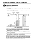
1
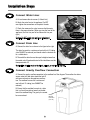
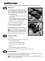
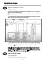
Installation Steps
STEP 1
P repare th e P lac em ent A rea
A. Clean the placement area.
B . Ex amine the inlet plumbing to ensure that the pipe is not plug g ed with lime, iron, or any other substance. Clean or replace plug g ed plumbing .
Note: A minimum three-quarter-inch plumbing is required between the pressure tank and the filter for
the filter to function properly.
C. Place your appliance in the desired location using the following diag ram as a g uide. The diag ram
applies to basement, slab, crawl space, and outside installations.
D . F or most installations, install the filter after the pressure tank or water meter and before the water
heater and any water softener appliance unless otherwise recommended. W hen installing the 9 00CF
Carbon F ilter for well water, place the filter after any water softener appliance unless otherwise recommended. Contact the H elpL ine for further assistance in determining the proper installation sequence.
Caution: If less than 10 feet of pipe connects the water treatment appliance(s) to the water heater,
then a check valve must be installed between the water treatment appliance and the water heater.
Install the check valve as close to the water heater as possible. Ensure that the water heater has an
adequately rated temperature and pressure safety relief valve.
STEP 2
T u rn O ff W ater Su pply
A. Turn off the water supply.
B . O pen the hot and cold water to depressuriz e the lines.
5
Installation Steps
STEP 3
Connect Water Lines
A. Lift and remove the valve cover. (Lift back first.)
B. Attach the water lines to the appliance. Do NOT
over– tighten the connections on the plastic threads.
C. Check the arrows on the valve to ensure that the water
flows in the proper direction. (When you view the front of the
appliance, the inlet is to your left and the outlet is to your
right.)
Caution: Do NOT plumb your appliance in backward.
STEP 4
See Installation Tips for
more information about
connecting water lines.
Connect D rain Line
A. Connect the drain line as shown in the figure to the right.
The drain line must be a minimum of one-half-inch I.D. tubing
(size CANNOT be reduced) and should make the shortest run
to a suitable drain.
B. The end of the drain line must be equal in height or lower than
the control valve. All overhead drains for filter installations must be
three-quarter-inch I.D.
Caution: The drain line must not be kinked, crimped, or restricted in any way.
STEP 5
Connect G rav ity Ov erflow Connection
A. Connect the gravity overflow connection to the overflow line. See diagram. The overflow line drains
excess water to a floor drain should the tank fill
with too much water or the appliance malfunction. The overflow line must be a minimum of
one-half-inch I.D. tubing (size CANNOT be
reduced).
B. Ensure that the overflow line ends at a drain
that is at least three inches lower than the bottom of the overflow fitting. The gravity line cannot
be run overhead.
6
G ravity
Overflow
Connection
(1/2” I.D.)
Installation Steps
STEP 6
F lush Lines
A. Ensure that the appliance is in bypass mode. See
diagram. The bypass valve can isolate the appliance should
the system malfunction or leak. The bypass valve enables
you to use untreated water for watering plants, shrubs, or
lawns. To engage the bypass
1. Locate the dial-shaped knob located on the rear of the
main control valve.
2. Turn the knob counter-clockwise until it stops and the
arrow points to "BY PASS". The appliance will be bypassed,
and all water to the home is raw, untreated water.
B. Turn on the water supply at a cold water tap.
C. R un the water for two to three minutes until the water
runs clear to flush the lines of any debris.
D. R eturn the appliance to service. Turn the knob
clockwise until it stops and the arrow points to "SER V ICE".
Note: To prevent untreated water from entering your home,
remember to not use water for inside home uses when the
appliance is in bypass mode. Ensure that you return the
appliance to service mode when watering is complete.
STEP 7
Check for Leak s
A. Close all faucets.
B. Check all lines and connections for leaks. If leaks are found
1. Turn off the main water supply.
2. Open a cold water tap to depressurize the lines.
3. Close the tap to eliminate any siphoning action.
4. R epair all leaks.
5. Turn on the main water supply and recheck for leaks.
C. R eplace valve cover. (Hook front first, then push down back to lock in place.)
STEP 8
F lush Appliance
A. Open a cold water tap and allow the appliance to flush for 20 minutes or until approximately 72 gallons
of water have passed through the appliance per NSF requirements.
Note: Do NOT plug in the transformer. See Start-U p Procedures for information about how to prepare and
program your appliance for proper operation.
7
Helpful Installation Tips
Q est Fitting s
Qest connection fittings are provided with your appliance. Qest fittings
provide a convenient easy-to-use three-piece assembly for three-quarterinch copper plumbing or three-quarter-inch CTS CPVC plastic tubing.
Ensure that the three components (1: collar, 2: metal retaining ring, and
3: nylon sleeve) are correctly installed in sequence on the pipe. See diagram.
3
2
1
Hard Plumb ing the B ypass With Copper
Fitting s
Do not use Qest fittings for hard plumbing the bypass connections with copper fittings. Instead, when preparing
male threaded fittings of the bypass valve, use the following guidelines to avoid damage to the plastic pipe threads.
A. Wrap the threads three times with one-half-inch wide Teflon tape. Place each consecutive wrap on top of the
previous wrap.
B. Use Teflon paste on the first two male threads only to prevent tearing of the tape. The paste lubricates the tape
and fills the small void areas that might exist between the threads. When the joint is complete, there will be a small
bead of sealant at the fitting interface, which indicates a properly joined connection.
C. Use a union with a threaded connection to facilitate repair of potential leaks in soldered joints.
D. Prepare the copper tail assemblies in advance to enable them to cool prior to final assembly. Advance preparation and cooling will prevent heat damage to the plastic pipe threads of the adapter.
E. Ensure that the copper tube is at least 3.5 inches long.
F. Turn the fitting counter-clockwise until you feel the threads engage and then tighten to prevent cross threading.
Do NOT over-tighten the fittings.
Caution: Do NOT allow heat from the torch to transfer to the plastic valve component, which could be damaged.
Plastic (PV C/CPV C) Pipe J oining Proced ures
To ensure reliable joint integrity when using solvent cement for pvc/cpvc plumbing, follow these recommendations:
A. Cutting— The pipe must be cut square to allow for the proper interfacing of the pipe end and the fitting socket
bottom. Use a wheel cutter, miter saw, or a ratchet shear for best results.
B. Deburring and Beveling— Use a knife, plastic pipe deburring tool, or a file to remove burrs from the end of the
pipe. Be sure to remove all burrs from the inside as well as the outside of the pipe. All pipe ends should be beveled
to permit easier insertion of the pipe into the fitting. Failure to bevel the pipe end may cause a "wiping" effect in the
fitting where the cement is forced to the end of the fitting socket. This creates a weak joint.
C. Test Dry Fit of the Joint— Tapered fitting sockets are designed so that an interference fit should occur when the
pipe is inserted about one-third to two-thirds of the way into the socket. Occasionally, when pipe and fitting dimensions are at the tolerance extremes, it will be possible to fully insert dry pipe to the bottom of the fitting socket.
When this happens, a sufficient quantity of cement must be applied to the joint to fill the gap between the pipe and
fitting.
8
Helpful Installation Tips
Plastic (PVC/CPVC) Pipe Joining Procedures (cont.)
D. Inspection, Cleaning, and Priming—Inspect the inside of the pipe and fitting sockets and remove dirt, grease, or
moisture with a clean dry cloth. If wiping fails to clean the surfaces, use a chemical cleaner. Check for possible
damage such as splits or cracks and replace if necessary. Use purple primer to penetrate and soften the bonding
surfaces of the PVC or CPVC pipe and fittings. Proceed without hesitation to the cementing procedure while the
primed surfaces are still wet.
E. Application of Solvent Cement—Apply the solvent cement evenly and quickly around the outside of the pipe
while the primer is still wet. Apply a light coat of cement evenly around the inside of the fitting socket. Do not allow
excess cement to "puddle" in the fitting. Apply a second coat of cement to the pipe end.
F. Joint Assembly—Working quickly, insert the pipe into the fitting socket and give a one-quarter turn of the pipe or
fitting while pushing toward the fitting stop. This action will evenly distribute the cement. Do NOT continue to rotate
the pipe or fitting after the stop has been reached. Hold the joint tightly together for about 15 seconds to prevent
the pipe from "creeping" out of the fitting. A good joint will have sufficient cement to make a small bead all the way
around the outside of the fitting hub. The joint should not be disturbed immediately after the cementing procedure.
Allow adequate time for the joint to cure properly. Exact drying time is hard to predict because of environmental
variables. Follow the recommended joint curing times on the primer and cement container labels.
Note: The next step is Start Up. Start-up procedures are provided for each of the following units
• 900CF Carbon Filter
• 900NF Acid Neutralizing Filter
• 900IF Iron Filter
Be sure to follow the Start-Up Procedure for your specific appliance.
9
Start-Up Procedures—900CF Carbon Filter
Important
The WaterBoss® 900CF Carbon Filter is capable of treating a combination of undesirable constituents (chlorine,
taste, and odor) in water. Install, set up, and use the filter within the operating limits outlined in this manual.
Failure to comply with these specifications may decrease the effectiveness of the backwash and cause control
valve malfunction.
STEP 1
Soak the Carbon Filter M edia
The granular activated carbon in the filter has been shipped dry. The filter media must soak for 24 hours
to prevent media loss to the drain during backwash. To soak the filter media, wait for 24 hours after completing the eight-step installation procedures as described in Installation Steps before you plug in the
transformer or use the appliance.
STEP 2
Plug in the Transformer
A. After 24 hours, plug the transformer into an appropriate outlet.
The transformer is 120 volt, 60 cycle ac for locations in the USA or 220 volt,
50 cycle ac for locations outside the USA.
B. Ensure that the outlet selected is NOT operated by an on/off switch.
STEP 3
Program the R egeneration Cycle
To ensure reliable performance and optimum efficiency, program the regeneration cycle (backwash) to
occur every one to four days based on local conditions. On the controller, set the frequency and time of
day for regeneration to occur. Follow the instructions provided in Setting the Controller.
STEP 4
Start the R egeneration Cycle
A. Press and hold the REGENERATE button until the controller indicates 01 (flashing). The regeneration
cycle begins.
B. Regeneration is complete after seven minutes and the appliance is returned to service mode. The
controller will display a number between 01 to 04. This number is the days until the next regeneration.
10
Start-Up Procedures —900NF Acid Neutralizing
Filter
Important
The WaterBoss® 900NF Neutralizing Filter is capable of elevating a low pH condition (acid) in your water. Install,
set up, and use the filter within the operating limits outlined in this manual. Failure to comply with these specifications may decrease the effectiveness of the backwash and cause control valve malfunction.
STEP 1
Plug in the Transformer
A. Plug the transformer into an appropriate outlet. The transformer is 120 volt,
60 cycle ac for locations in the USA or 220 volt, 50 cycle ac for locations outside
the USA.
B. Ensure that the outlet selected is NOT operated by an on/off switch.
STEP 2
Program the Regeneration Cycle
To ensure reliable performance and optimum efficiency, program the regeneration cycle (backwash) to
occur every one to two days based on local conditions. On the controller, set the frequency and time of
day for regeneration to occur. Follow the instructions provided in Setting the Controller.
STEP 3
Start the Regeneration Cycle
Before placing the filter in service, backwash the filter to remove fine media particles in the filter bed.
To backwash the filter, start the regeneration cycle as follows:
A. Press and hold the REGENERATE button until the controller indicates 01 (flashing). The regeneration cycle begins.
B. Regeneration is complete after seven minutes, and the appliance returns to service mode. The controller will display a number between 01 to 02. This number is the days until the next regeneration.
STEP 4
Adjust Water Softener Hardness Setting
Typically, hardness will increase by two to four grains after passing through the neutralizing filter. If you
have a water softener, after implementing the start-up steps for the acid neutralizing filter
A. Test the hardness of the water before it enters the water softener.
B. Reset the hardness setting appropriately on the water softener.
Note: The 900NF appliance requires periodic (annual) replenishment of the neutralizing media that
adjusts the pH level of the water. See Replenishment Procedure.
11
Start-Up Procedures—900IF Iron Filter
Important
The WaterBoss® 900IF Iron Filter is capable of treating a combination of undesirable constituents (iron and/or
hydrogen sulfide) in water. Install, set up, and use the filter within the operating limits outlined in this manual.
Failure to comply with these specifications may decrease the effectiveness of the backwash and cause control
valve malfunction.
Water Testing—The 900IF Iron Filter, like any other appliance, requires correct installation and setting for optimum
performance. To ensure proper settings, you need to have a sample of your untreated water tested for iron and pH.
To find a facility to test your water sample, check your Yellow Pages under Water Analysis or Water Testing or contact the company below to conduct a test for you.
WATERSCREEN
National Testing Laboratories, Inc.
1-800-458-3330 from 9 a.m. to 5 p.m. EST
A pH of seven or above is necessary for the 900IF Iron Filter to function properly.
STEP 1
Add Water
A. Slowly fill the media tank until water flows steadily at the outlet.
B. Once filled, turn off water and allow the water to set for 10 minutes.
C. After 10 minutes, backwash for up to 25 minutes.
D. Put the controller back into service position.
STEP 2
Add Potassium Permanganate
A. Open the port lid and add three
gallons of water.
B. Slowly add three pounds of potassium
permanganate. Coarse granular
potassium permanganate (P/N 97804)
is recommended. Do not use fine
granular potassium permanganate since
it can be drawn into the filter as a solid
rather than as a liquid.
Caution: Use care when handling potassium permanganate. Refer to the product label for further operating and handling instructions.
C. Thoroughly mix with a clean wooden paint paddle. (Do NOT use plastic.) Stir the potassium permanganate until the color is a dark walnut.
Note: Stir the potassium permanganate and water mixture every two weeks. If the water is a pink color,
add another three pounds of potassium permanganate. Potassium permanganate will last approximately three to six months.
12
Start-Up Procedures—900IF Iron Filter
STEP 3
Plug in the Transformer
A. Wait 15 minutes after adding potassium permanganate.
B. Plug the transformer into an appropriate outlet. The transformer is
120 volt, 60 cycle ac for locations in the USA or 220 volt, 50 cycle ac for
locations outside the USA.
C. Ensure that the outlet selected is NOT operated by an on/off switch.
STEP 4
Start the Regeneration Cycle
A. Press and hold the REGENERATE button until the controller indicates 01
(flashing). The regeneration cycle begins.
During regeneration, water bypasses the appliance to allow iron and
sediment to wash down the drain through the following six-step process:
1. First Upflow Backwash—A rapid upflow of water flushes out the media
bed.
2. Regeneration—Regenerant is drawn out of the solution cabinet and up through the media tank,
cleaning the media bed and releasing accumulated iron and hydrogen sulfide.
3. Slow Rinse—A slow upflow rinse process that flushes out the regenerant and iron.
4. Second Upflow Backwash—This upflow backwash flushes out any remaining regenerant and
sediment from regeneration.
5. Downflow Clean Water Refill—Filtered water is directed to the solution cabinet to prepare the
regenerant for the next regeneration sequence.
6. Return to Service—Regeneration is complete after approximately 45 minutes and the appliance is
returned to service mode. The controller will display a number between 01 to 14. This number is the
days to next regeneration.
13
Start-Up Procedures—900IF Iron Filter
STEP 5
Program the Regeneration Cycle
A. To ensure reliable performance and optimum efficiency, program the regeneration cycle to occur every
one to fourteen days. Use the following worksheet to determine the appropriate frequency for scheduling
the regeneration cycle for your appliance. Use the example as a guide.
Regeneration Cycle Frequency Worksheet
Your Water
Total Iron
Example
_2.4_ ppm × 1 =
2.4 ppm
+ Manganese*
_____ ppm × 1 = ____ ppm
_____ ppm × 3 = ____ ppm
_0.2_ ppm × 3 =
0.6 ppm
+ Sulfur
_____ ppm × 5 = ____ ppm
_1.0_ ppm × 5 =
5.0 ppm
= Total compensated ppm
____ ppm
8.0 ppm
75 gal
75 gal
____ ppm
600 ppm
× Number of people in household
____ people
_3 people
= Daily ppm capacity
____ ppm
1800 ppm
× Gallons per day for one person
= ppm per person per day
=
Iron filter capacity
=
5600 ppm
5600 ppm
÷ Daily ppm capacity
=
____ ppm
1800 ppm
____ days
3.1 days
@ ____ days
_3_ days
= Frequency of regeneration
Set regeneration frequency
*If manganese is unknown, multiply the iron and sulfur total by 1.15 to adjust total compensated ppm.
B. On the controller, set the frequency and time of day for regeneration to occur. Follow the instructions
provided in Setting the Controller.
STEP 6
Determine Monthly Potassium Permanganate Usage
A. Use the regeneration cycle frequency determined in Step 5 and the following worksheet to determine the monthly potassium permanganate usage. Use the example as a guide.
Monthly Potassium Permanganate Usage Worksheet
Your Water
Example
Total days per month
____ days
30 days
÷ Frequency of regeneration
____ days
_ 3 days
= Regenerations per month
____ regenerations
_ 10 regenerations
× 2.8 oz per regeneration =
oz potassium permanganate per month
____ oz
÷ 16 = lb per month
____ lb
14
_ 28 oz
1.75 lb
Setting the Controller
To ensure that your WaterBoss® Filter operates properly, set the controller as follows:
STEP 1
Set the Freq uency of Regeneration or Backwash
A. Press and hold the SET button for three seconds. When “01” displays, release the SET button.
B. Press and release the CHANGE button until the desired frequency number displays.
C. Press the SET button to return to the main screen. The number you selected will be displayed. This
number indicates the number of days until the next regeneration or backwash.
STEP 2
Set the Time
A. Press and hold the SET and CHANGE buttons simultaneously for three seconds. Release when the
number “12” appears in the display. The number 12 indicates standard time in AM or PM.
Note: To change to military time, press the CHANGE button and the “12” will change to “24”. For military time, be sure to set the correct time of day after 12 noon. For example, 2:00 p.m. will be set as
14:00.
B. Press and release the SET button to set the time (to the nearest hour). The display will read “set
time”.
STEP 3
Set the Time of Regeneration/Backwash
A. Press the SET button to toggle to the final setting. The display will read, “set reg. time” 02 AM. This
setting is 2:00 a.m.
B. Press the CHANGE button to select the desired regeneration time.
C. Press the SET button to save the program you have entered.
Note: If you have a softener installed with the filter, stagger the regeneration times. Set the softener to
regenerate first, followed by the filter.
15
Replenishment Procedure —900NF Acid
Neutralizing Filter
The 900NF appliance requires periodic (annual) replenishment of the neutralizing media that adjusts the pH level
of the water. Use the freeboard distance as described in the following section and the diagram to determine the
amount of media needed to adjust the bed depth to maintain optimum performance of the neutralizer.
Tools and Materials Needed
The following tools and materials are needed to replenish the acid neutralizer:
• Analog scale (do NOT use a digital scale)
• Replacement media (P/N M050)
• Five-gallon bucket with handle
• Funnel with one-inch fill tube
• 0.5-inch, four-foot long siphon hose
• Three-quarter-inch socket with ratchet
• 12-inch wooden ruler (or wooden dowel rod and a
tape measure)
Replenishment Procedure
The replenishment procedure is as follows:
STEP 1
Turn Off the Water
A. Turn off the water to the appliance.
B. Open a tap to depressurize the appliance.
C. Close the tap.
STEP 2
*
Siphon Off All Water
A. Use the three-quarter-inch socket to
remove the fill plug from the media tank.
A dd 9 lb s .
B. Insert a siphon hose into the fill port and
siphon off all water down to the media level in
the tank into a five-gallon bucket.
STEP 3
Determine Amount of
Replenishment Media
Required
R ec o m m en ded freeb o ard
Media Bed
A. Use a wooden ruler to measure the freeboard distance from the top of the fill plug to the media.
B. The recommended freeboard is 6.5 inches. Add 4.5 lb of media per inch below 6.5 inches.
Example:
Measured Freeboard
8.5 in.
6.5 in.
Minus Factory Freeboard
Equals Adjusted Freeboard
2.0 in.
Replenishment equals 4.5 lb media X 2.0 in. (adjusted freeboard) = 9 lb media
16
Replenishment Procedure —900NF Acid
Neutralizing Filter
STEP 4
Add Replenishment Media
A. Measure the required amount of media (P/N M050) by weight on an analog scale.
B. Place a funnel into the fill port and pour the media into the tank.
STEP 5
Fill the Tank With Water
A. Open the main water valve and slowly fill the tank with water up to the bottom of the fill port.
B. Turn off the water.
C. Make sure the threads of the fill port are clean and replace the fill plug.
Caution: Do NOT over-tighten the fill plug.
STEP 6
Check For Leaks
A. Turn on the water to re-pressurize the appliance and check for leaks. See Installation Steps for
further information about how to check for leaks.
B. Correct any evident leaks.
17