1
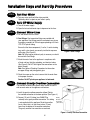
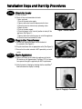
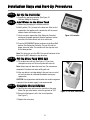
Installation Steps and StartUp Procedures
STEP 1
Prepare the Placement Area
A . C lean the placement area.
B . T urn off the electricity and w ater supply to the w ater heater. F or g as w ater heaters, turn the g as
cock to “P IL O T .”
C . E x amine the inlet plumbing to ensure that the pipe is not plug g ed w ith lime, iron, or any other
substance. C lean or replace plug g ed plumbing .
A ir G a p
F ig u re 1 : A p p lia n c e P la c e m e n t
D. Make sure the inlet/outlet and drain connections meet the applicable state and local codes.
E . C heck the arrow s on the by pass v alv e to ensure that the w ater flow s in the proper direction.
C a u tio n : Do not plumb the appliance in backw ard.
F . P lace y our appliance in the desired location using F ig ure 1 as a g uide. T he diag ram applies to
basement, slab, and craw l space.
G . F or most installations, install the appliance after the pressure tank and any w ater filter appliance or
w ater meter and before the w ater heater unless otherw ise recommended.
W a te r H e a te rs : If less than 1 0 feet (3 .0 m) of pipe connects the w ater treatment appliance(s) to the
w ater heater, then a check v alv e must be installed betw een the w ater treatment appliance and the
w ater heater. Install the check v alv e as close to the w ater heater as possible. E nsure that the w ater
heater has an adeq uately rated temperature and pressure safety relief v alv e.
5
Installation Steps and Start-Up Procedures
STEP 2
Test Your Water
A. Test your water quality with the strips provided.
Optionally, obtain a report on your water's quality.
STEP 3
Turn Off Water Supply
A. Turn off the water supply.
B. Open the hot and cold water taps to depressuriz e the lines.
STEP 4
Connect Water Lines
A. Lift and remove the valve cover.
B. Qest fittings. Q est connection fittings are provided with
your appliance. Q est fittings provide a convenient easy-to-use
three-piece assembly for 3/4 -inch copper plumbing or 3/4 -inch
CTS CPV C plastic tubing.
3
Ensure that the three components (1: collar, 2 : metal retaining
ring, and 3: nylon sleeve) are correctly installed in sequence
on the pipe. (S ee Figure 2 .)
N ote: N o Teflon tape or plumber's putty is necessary or should
be used with Q est fittings.
2
1
Figure 2: Qest Fittings
C. Attach the water lines to the appliance in compliance with
all state and local, building, plumbing, and electrical codes.
(S ee Figure 3.) Do N OT over tighten the connections on the
plastic threads.
N ote: S ee Optional Plumbing Procedures for information
on copper fittings and joining plastic pipe.
D. Check the arrows on the valve to ensure that the water flows
in the proper direction.
Figure 3: Connect Water L ines
Caution: D o N O T plumb y our appliance in b ack w ard .
STEP 5
Connect Gravity Overflow Connection
The overflow line drains away excess water should the tank fill
with too much water or the appliance malfunctions.
A. Install the gravity overflow connection (elbow). R otate
the overflow connection to the down position. (S ee Figure 4 .)
B. Connect 1/2 -inch I.D. tubing (siz e CAN N OT be
reduced) to the gravity overflow connection. This tubing
is not supplied with the appliance. R oute the overflow
line to a drain that is at least three inches (7 6 mm)
lower than the bottom of the overflow connection.
The gravity overflow line cannot be run overhead.
Gravity
Overflow
Connection
(1/2 -inch I.D.)
Figure 4 : Grav ity O v erflow Connection
6
Installation Steps and Start-Up Procedures
STEP 6
Connect Drain Line
The drain line drains away the backwash water as
part of the regeneration cycle.
A. Connect the drain line to the drain end cap (as shown in
Figure 5 ) with a minimum of 1/2-inch I.D. tubing (size CANNOT
be reduced). This tubing is supplied with the appliance.
B. Route the drain line to a floor drain, laundry tub, or other
suitable waste receptor. Maintain a minimum 2-inch (5 0 mm)
air gap between the drain line and the flood level rim of the
waste receptor to prevent back-siphoning. This drain line
should make the shortest run to the suitable drain.
Figure 5: Connect Drain Line
C. The drain line may be elevated up to 8 feet (2.4 m) from the
discharge on the appliance as long as the water pressure in
your system is 40 psi (2.8 bar) or more.
D. If the drain line is 25 feet (7.6 m) or longer, increase the drain line
to 3/4-inch I.D. The end of the drain line must be equal to or lower
in height than the control valve.
Caution: The drain line must not be kinked, crimped, or restricted in any way.
STEP 7
Flush Lines
A. Place the appliance in the bypass position and turn on the
main water supply. (See Figure 6.)
B. Open the nearest cold water faucet to flush the plumbing
of any excess soldering flux, air, or any other foreign material.
Figure 6: B ypass Position
7
Installation Steps and Start-Up Procedures
STEP 8
Check for Leaks
A. Close all faucets.
B. Check all lines and connections for leaks.
If leaks are found
1. Turn off the main water supply.
2. Open a cold water faucet to depressurize the lines.
3. Close the faucet to eliminate any siphoning action.
4. Repair all leaks.
5. Turn on the water supply.
6. Place the bypass in the “service” position to slowly fill the
appliance. (See Figure 7.)
7. Open a cold water faucet to purge air out of the appliance.
8. Close the faucet and recheck for leaks.
STEP 9
Figure 7: Service Position
Plug in the Transformer
A. Connect the transformer power cord to the back of
the controller. (See Figure 8.)
B. Plug the transformer into an appropriate outlet.(See Figure 9 .)
C. Ensure that the outlet selected is NOT operated by an on/off
switch.
STEP 10
Flush Appliance
A. Open a cold water tap and allow the appliance to flush for
20 minutes or until approximately 72 gallons (273 L) of water
have passed through the appliance per NSF requirements.
Figure 8: Connect power cord
B. Verify that water is flowing by checking that the waterMizer™
flow indicator on the display is rotating.
Figure 9 : Plugging in Transformer
8
Installation Steps and Start-Up Procedures
STEP 11
Set Up the Controller
A. Program the appliance controller (See Figure 10.
Also see Setting the Controller).
STEP 12
Add Water to the Brine Tank
A. Remove any packaging or installation materials.
B. Add 2 gallons (7.6 L) of water to the brine tank. After the first
regeneration, the appliance will automatically refill the correct
amount of water into the brine tank.
C. Initiate a manual regeneration (See Setting the Controller)
and inspect for proper operation. Allow the appliance to draw
water out of the brine cabinet until the air check sets.
Figure 10: Controller
D. Press the REGENERATE button to advance to the Brine Refill
position (See Setting the Controller). The tank fills with the
proper amount of water. The controller will then step the valve
to the H ome position.
Note: This initial start up is the ONLY time you will add water to the
brine tank. Do NOT add water at any other time.
STEP 13
Fill the Brine Tank With Salt
A. Fill the brine tank with salt. (See Figure 11.) U se clean,
white pellet or solar salt. Do not mix pellet with solar salt.
Note: Always keep salt above the water level. For convenience,
completely fill the brine tank when refilling with salt.
B. After you add salt, including adding it after you have run out of
salt, wait two hours for saturated brine before starting any
regeneration.
CAU TION: U se of potassium chloride when iron and/or manganese
is present in the raw water supply is not recommended.
STEP 14
Complete the Installation
A. Open the inlet valve and turn on the electricity to the water
heater. For gas water heaters, return the gas cock to “ON.”
B. Ensure that the bypass is left in the “service” position.
(See Figure 7.)
C. Replace the valve cover.
9
Figure 11: Fill Brine Tank With Salt
Optional Plumbing Procedures
This section provides information on plumbing with copper fittings and with plastic pipe.
Hard Plumbing the Bypass With Copper Fittings
Do not use Qest fittings for hard plumbing the bypass connection with copper fittings. Instead, when preparing
male threaded fittings of the bypass valve, use the following guidelines to avoid damage to the plastic pipe threads.
A. W rap the threads three times with 1/2-inch wide Teflon tape. Place each consecutive wrap on top of the
previous wrap.
B. Use Teflon paste on the first two male threads only to prevent tearing of the tape. The paste lubricates the tape
and fills the small void areas that might exist between the threads. W hen the joint is complete, there will be a
small bead of sealant at the fitting interface, which indicates a properly joined connection.
C. Use a union with a threaded connection to facilitate repair of potential leaks in soldered joints.
D. Prepare the copper tail assemblies in advance to enable them to cool prior to final assembly. Advance
preparation and cooling will prevent heat damage to the plastic pipe threads of the adapter.
E. Ensure that the copper tube is at least 4 inches (10 cm) long.
F. Turn the fitting counter-clockwise until you feel the threads engage and then tighten to prevent cross threading.
Do NOT over tighten the fittings.
Caution: Do NOT allow heat from the torch to transfer to the plastic valve component, which could be
damaged.
10
Optional Plumbing Procedures
Plastic (PVC/CPVC) Pipe Joining Procedures
To ensure reliable joint integrity when using solvent cement for PVC/CPVC plumbing, follow these
recommendations:
A. Cutting— The pipe must be cut square to allow for the proper interfacing of the pipe end and the fitting socket
bottom. Use a wheel cutter, miter saw, or a ratchet shear for best results.
B. Deburring and Beveling— Use a knife, plastic pipe deburring tool, or a file to remove burrs from the end of the
pipe. Be sure to remove all burrs from the inside as well as the outside of the pipe. All pipe ends should be
beveled to permit easier insertion of the pipe into the fitting. Failure to bevel the pipe end may cause a “wiping”
effect in the fitting where the cement is forced to the end of the fitting socket. This creates a weak joint.
C. Test Dry Fit of the J oint— Tapered fitting sockets are designed so that an interference fit should occur when
the pipe is inserted about one-third to two-thirds of the way into the socket. Occasionally, when pipe and fitting
dimensions are at the tolerance extremes, it will be possible to fully insert dry pipe to the bottom of the fitting
socket. When this happens, a sufficient quantity of cement must be applied to the joint to fill the gap between
the pipe and fitting.
D. Inspection, Cleaning, and Priming— Inspect the inside of the pipe and fitting sockets and remove dirt, grease,
or moisture with a clean dry cloth. If wiping fails to clean the surfaces, use a chemical cleaner. Check for
possible damage such as splits or cracks and replace if necessary. Use purple primer to penetrate and soften
the bonding surfaces of the PVC or CPVC pipe and fittings. Proceed without hesitation to the cementing
procedure while the primed surfaces are still wet.
E. Application of Solvent Cement— Apply the solvent cement evenly and quickly around the outside of the pipe
while the primer is still wet. Apply a light coat of cement evenly around the inside of the fitting socket. Do not
allow excess cement to “puddle” in the fitting. Apply a second coat of cement to the pipe end.
F. J oint Assembly— Working quickly, insert the pipe into the fitting socket and give a one-quarter turn of the pipe or
fitting while pushing toward the fitting stop. This action will evenly distribute the cement. Do NOT continue to
rotate the pipe or fitting after the stop has been reached. Hold the joint tightly together for about 15 seconds to
prevent the pipe from “creeping” out of the fitting. A good joint will have sufficient cement to make a small bead
all the way around the outside of the fitting hub. The joint should not be disturbed immediately after the
cementing procedure. Allow adequate time for the joint to cure properly. Exact drying time is hard to predict
because of environmental variables. Follow the recommended joint curing times on the primer and cement
container labels.
11
Setting the Controller
STEP 1
Determine the Controller Setting Number
A. For municipal water, call the water department to determine
the hardness and pH of your water supply.
B. For well water, use the hardness test strips provided with your
appliance or have a sample of your untreated water tested by a
water testing laboratory.
1. Test Strips—Follow the instructions on the test strips.
If the color on your test strip is between two readings,
use the higher number. This number gives the hardness
in grains per gallon and parts per million (mg/L).
Figure 12: Hardness Test Strips
2. Testing Laboratory—To ensure proper settings, have a sample of your untreated water tested
for iron and pH. To find a facility to test your water sample, check your Yellow Pages under Water
Analysis or Water Testing or contact the company below to conduct a test for you.
WATERSCREEN
National Testing Laboratories, Inc.
1-800-458-3330 from 9 a.m. to 5 p.m. EST
3. If the pH is below seven and you have a 700 or 900 unit, call the HelpLine listed in Questions.
C. Determine the controller setting as follows:
Y our Water
Enter hardness grains per gallon (mg/L)
If your water contains iron, add 15 (257)
The sum is your controller setting number
+
+
Ex ample
20
15
35
M etric Ex ample
342
257
600 (rounded)
D. If your water supply has an excessive amount of iron, do not add 15 to the grains per gallon
hardness (257 mg/L). Instead enter the hardness grains per gallon (mg/L) as your controller setting
Note: See the powerClean™ feature in Understanding the Controller.
STEP 2
Enter Your Setting Number Into the Controller
A. Press and hold the SET button for about 5 seconds until the digits 25
appear in the display.
B. Press the CHANGE button until the display matches your
compensated number.
Once you pass “70” (models 700 and 950) or “90” (model 900),
the display will reset to “03”.
C. Press the SET button to save the hardness setting number.
D. To recheck the hardness setting number, hold down the SET button
for about 5 seconds.
Figure 13: Controller
Note: Refer to Specifications for the maximum water hardness that your appliance can handle. Your
controller is now set.
12
Understanding the Controller
Demand Mode
The controller is now in Demand Mode which means you will not have to worry about
vacation settings or extra guests because the controller measures water usage and
regenerates based on need. The appliance will regenerate using only the necessary
amount of water and salt. If your power has been off, the appliance will retain
programmed settings indefinitely.
Note: You should not need to change from Demand Mode.
Soft Water Remaining
After setting water hardness, the display shows the gallons (or litres) of soft water
remaining until the next automatic regeneration. Typically, each person in the household
uses about 75 gallons (284 L) per day. Water remaining is in gallons in hundreds
(or litres in thousands), for example 88 = 8,800 gallons (33 = 33,000 litres).
Figure 14: Controller
Recharge/Regeneration Status
Regeneration cycle numbers are shown during regeneration. The read-out will flash with the cycle number. The
flashing regeneration numbers are:
First cycle
Second and Third cycles
Fourth cycle
Fifth cycle
Sixth cycle
(01) First Backwash
(02) Brine/Slow Rinse
(03) Second Backwash
(04) Brine Refill
(HO) Service
To quickly advance through the regeneration cycles, press and hold the REGENERATE button for 2 to 5 seconds
until the cycle begins. After 20 seconds press and hold the REGENERATE button until the cycle number changes
(about 2 seconds). Each cycle can be advanced in this manner.
waterMizer™
The waterMizer™ indicator will turn whenever water is being used.
Regenerate Button
To start an immediate regeneration, press the REGENERATE button and hold for 2 to 5 seconds. The
REGENERATE button is used when starting your water conditioner, to start an immediate regeneration, or to restore
capacity if you run out of salt.
Out of Salt
Should your appliance run out of salt, you may not have soft water available.
A. Open the salt lid and add salt.
B. Wait two hours, then press the REGENERATE button and hold for 2 to 5 seconds.
C. Regeneration takes approximately 12 to 45 minutes. After regeneration the appliance is returned to service mode.
13
Understanding the Controller
powerClean™ Feature
The powerClean™ feature is a service/maintenance step for water supplies that have an excessive amount of iron.
Activate this feature by pushing the POWERCLEAN button on the controller. When this feature is activated,
powerClean™ will appear in the display.
The appliance will regenerate every other day with five pounds (2.3 kg) of salt. Leave the powerClean™ feature on
for a minimum of two weeks. The frequent regeneration will eliminate iron buildup in the resin bed. The use of salt
with an iron cleaning agent or iron out cleaner is recommended for continuous use as a preventive measure against
iron fouling of the resin bed.
Deactivate this feature by pushing the POWERCLEAN button. Use this feature every six months as a part of your
routine maintenance procedure to ensure a long service life for your water treatment appliance.
Advanced Customer Settings
You can use the digital display to reset the controller settings if the factory default settings are not suitable for your
needs. Most customers will want to use the factory default settings.
Set High Capacity or High Efficiency
Your appliance can be programmed for High Capacity (HC) or High Efficiency (HE). High Capacity means the
appliance will regenerate less often, but use more salt. High Efficiency will make the appliance regenerate more
often and use less salt. This is the default. High efficiency setting meets or exceeds the requirement some states
have for salt efficiency.
A. Hold down the SET button and CHANGE buttons for 3 seconds to enter advanced customer settings mode.
While SET and CHANGE are being held down, the display should show only the controller type. After 3 seconds,
the entire screen is lit for a half second, and then “HC” will appear.
B. Press and release the CHANGE button to toggle the digit display between “HC” and “HE”.
C. When the desired value is displayed, press and release the SET button.
Note: Choosing HE will make sure the appliance chooses salt settings that get 4,000 grains per pound
(570 grams/kg) of salt for each regeneration or better. This choice meets or exceeds the requirement some
states currently have in regards to salt efficiency.
All Models Are Eq uipped With Patented Capacity Guard
Set Demand and Delay Mode
D. The controller will display “Demand Mode”. Each press of the CHANGE button will switch between
“Demand Mode” and “Delay Mode”.
• Delay Mode allows regeneration at a specific time (for example, at 2 a.m. when less water is typically
being used).
• Demand Mode triggers a regeneration as soon as softening capacity is exhausted. This is the default.
E. When the desired setting is displayed, press and release the SET button.
14
Understanding the Controller
Advanced Customer Settings (cont.)
Set Hours Until R egeneration
F. “96 Hours” is now displayed. Press and release the CHANGE button to toggle this on and off. If “96 Hours” is
selected, the appliance will work no more than 4 days without a regeneration. Default is for “96” Hours” to be ON.
Note: If there is iron in your water, select this option.
G. When the desired setting is displayed, press and release the SET button.
Set Gallons or Litres
H. “Gallons X 100” is now displayed. Press and release the CHANGE button to toggle between “Gallons X 100” and
“Litres X 1000”. Choosing “Gallons” sets the controller to English units, and choosing “Litres” sets it to metric
units.
I. When the desired setting is displayed, press and release the SET button.
Set Time Format
J . If “Gallons” were chosen, “12” is now displayed. If “Litres” were chosen, “24” is displayed. Pressing and releasing
the CHANGE button will toggle between “24” and “12”. This controls the selection of a 12-hour (AM/PM) or
24-hour clock. If 24-hour, 00=midnight.
K . When the desired setting is displayed, press and release the SET button.
Set Time
L. “Set Time” and “12” is now displayed. To set the time, press and release the CHANGE button until the correct
time is displayed. Default is 12 PM.
Note: Set the time to the nearest hour.
M. When the desired setting is displayed, press and release the SET button.
Set R egeneration Time
N. “Set Reg. Time” and “02” is now displayed. To set the regeneration time, press and release the CHANGE button
to advance the numerical display. Default is 2 AM.
O. When the desired setting is displayed, press and release the SET button to save the “regen. time” displayed.
P. The appliance has been placed into operation.
Programming Is Now Complete
15