1
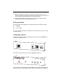
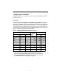
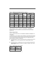
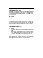
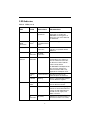
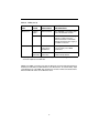
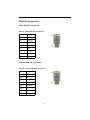
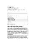
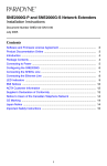
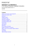
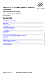
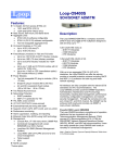
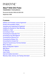
SNE2000-P, SNE2000-S, SNE2000Q-P and SNE2000Q-S Network Extenders Installation Instructions Document Number SNE2-A2-GN10-00 October 2004 Contents Software and Firmware License Agreement ................................................. 1 Package Contents ........................................................................................ 3 Connecting to Power .................................................................................... 3 Configuring the SNE2000 ............................................................................. 4 Connecting the SDSL Line ........................................................................... 6 Connecting the Ethernet Line ....................................................................... 6 LED Indicators .............................................................................................. 7 EMI Notices .................................................................................................. 10 Important Safety Instructions ........................................................................ 10 Product Documentation Online ..................................................................... 11 Software and Firmware License Agreement ONCE YOU HAVE READ THIS LICENSE AGREEMENT AND AGREE TO ITS TERMS, YOU MAY USE THE SOFTWARE AND/OR FIRMWARE INCORPORATED INTO THE PARADYNE PRODUCT. BY USING THE PARADYNE PRODUCT YOU SHOW YOUR ACCEPTANCE OF THE TERMS OF THIS LICENSE AGREEMENT. IN THE EVENT THAT YOU DO NOT AGREE WITH ANY OF THE TERMS OF THIS LICENSE AGREEMENT, PROMPTLY RETURN THE UNUSED PRODUCT IN ITS ORIGINAL PACKAGING AND YOUR SALES RECEIPT OR INVOICE TO THE LOCATION WHERE YOU OBTAINED THE PARADYNE PRODUCT OR THE LOCATION FROM WHICH IT WAS SHIPPED TO YOU, AS APPLICABLE, AND YOU WILL RECEIVE A REFUND OR CREDIT FOR THE PARADYNE PRODUCT PURCHASED BY YOU. The terms and conditions of this License Agreement (the “Agreement”) will apply to the software and/or firmware (individually or collectively the “Software”) incorporated into the Paradyne product (the “Product”) purchased by you and any derivatives obtained from the Software, including any copy of either. If you have executed a separate written agreement covering the Software supplied to you under this purchase, such separate written agreement shall govern. 1 Paradyne Corporation (“Paradyne”) grants to you, and you (“Licensee”) agree to accept a personal, non-transferable, non-exclusive, right (without the right to sublicense) to use the Software, solely as it is intended and solely as incorporated in the Product purchased from Paradyne or its authorized distributor or reseller under the following terms and conditions: 1. Ownership: The Software is the sole property of Paradyne and/or its licensors. The Licensee acquires no title, right or interest in the Software other than the license granted under this Agreement. 2. Licensee shall not use the Software in any country other than the country in which the Product was rightfully purchased except upon prior written notice to Paradyne and an agreement in writing to additional terms. 3. The Licensee shall not reverse engineer, decompile or disassemble the Software in whole or in part. 4. The Licensee shall not copy the Software except for a single archival copy. 5. Except for the Product warranty contained in the manual, the Software is provided “AS IS” and in its present state and condition and Paradyne makes no other warranty whatsoever with respect to the Product purchased by you. THIS AGREEMENT EXPRESSLY EXCLUDES ALL OTHER WARRANTIES, WHETHER EXPRESS OR IMPLIED, OR ORAL OR WRITTEN, INCLUDING WITHOUT LIMITATION: a. Any warranty that the Software is error-free, will operate uninterrupted in your operating environment, or is compatible with any equipment or software configurations; and b. ANY AND ALL IMPLIED WARRANTIES, INCLUDING WITHOUT LIMITATION IMPLIED WARRANTIES OF MERCHANTABILITY, FITNESS FOR A PARTICULAR PURPOSE AND NON-INFRINGEMENT. Some states or other jurisdictions do not allow the exclusion of implied warranties on limitations on how long an implied warranty lasts, so the above limitations may not apply to you. This warranty gives you specific legal rights, and you may also have other rights which vary from one state or jurisdiction to another. 6. IN NO EVENT WILL PARADYNE BE LIABLE TO LICENSEE FOR ANY CONSEQUENTIAL, INCIDENTAL, PUNITIVE OR SPECIAL DAMAGES, INCLUDING ANY LOST PROFITS OR LOST SAVINGS, LOSS OF BUSINESS INFORMATION OR BUSINESS INTERRUPTION OR OTHER PECUNIARY LOSS ARISING OUT OF THE USE OR INABILITY TO USE THE SOFTWARE, WHETHER BASED ON CONTRACT, TORT, WARRANTY OR OTHER LEGAL OR EQUITABLE GROUNDS, EVEN IF PARADYNE HAS BEEN ADVISED OF THE POSSIBILITY OF SUCH DAMAGES, OR FOR ANY CLAIM BY ANY THIRD PARTY. 7. The rights granted under this Agreement may not be assigned, sublicensed or otherwise transferred by the Licensee to any third party without the prior written consent of Paradyne. 8. This Agreement and the license granted under this Agreement shall be terminated in the event of breach by the Licensee of any provisions of this Agreement. 2 9. Upon such termination, the Licensee shall refrain from any further use of the Software and destroy the original and all copies of the Software in the possession of Licensee together with all documentation and related materials. 10. This Agreement shall be governed by the laws of the State of Florida, without regard to its provisions concerning conflicts of laws. Package Contents Unpack and Inspect the Equipment. The following components should be included: 1 SNE2000 1 Power supply If there is any visible damage, do not attempt to connect the device. Contact your sales or service provider. Connecting to Power Plug the power supply into the Power Adapter port on the back of the SNE2000 and connect it to your power source. Power Adapter Configuration 1 2 3 4 Ethernet Connection 5V DC SDSL Connection 04-17587 Verify that the Power LED on the front of the SNE2000 is illuminated. SDSL Network Extender 2000 SNE2000 Available SDSL Connection Power Collision Rx Tx Ethernet Connection Lnk 04-17586 Upon startup, the Ethernet link will remain disabled (as indicated by solid illumination of the Ethernet Rx, Tx, and Lnk LEDs) until the SDSL connection has been established. 3 Configuring the SNE2000 Configuration switches for the SDSL port are on the back of the SNE2000, numbered from left to right, 1-4. Bandwidth Switches 1–3 configure bandwidth on the SNE2000-P and SNE2000Q-P. Switches 1–3 on the SNE2000-P and SNE2000Q-P provide eight bandwidth options for the SDSL port. Distance capabilities listed in the following tables assume the use of 26 American Wire Gauge (AWG) cable. Connections made with cable of a heavier gauge will link up at greater distances. Your SNE2000 may not link up if the cable is in poor condition or if the cable distance is greater than a particular bandwidth will support; if a link is acheived under such conditions, traffic quality may be affected. Table 1. SNE2000-P Bandwidth and Distance Options Switch Position Bandwidth (kbps) Feet Distance 1 2 3 down down down 2,320 11,000 3,353 down down up 2,064 11,900 3,627 down up down 1,552 12,600 3,840 down up up 1,040 15,500 4,724 up down down 784 16,000 4,877 up down up 528 17,900 5,456 up up down 400 18,900 5,761 up up up Adaptive* Varies Meters Varies * Adaptive mode allows the SNE2000-P to train up to the best possible speed supported by the SNE2000-P, the remote modem to which it is connected, and the copper cable pair connecting the two. The maximum distance for an SNE2000-P in Adaptive mode is 24,700 feet (at 144 kbps). The SNE2000Q-P does not have Adaptive capability. 4 Table 2. SNE2000Q-P Bandwidth and Distance Options Switch Position Distance 1 2 3 Bandwidth (kbps) Feet down down down 2,320 10,400 3,170 down down up 2,064 10,800 3,292 down up down 1,552 13,400 4,084 down up up 1,040 14,800 4,511 up down down 784 15,800 4,816 up down up 528 17,400 5,304 up up down 400 18,200 5,547 up up up 272 19,200 5,852 Meters NOTE: Bandwidth cannot be configured on the SNE2000-S or SNE2000Q-S. Subscriber units determine bandwidth via communication with their partner SDSL provider units. Ethernet Duplex Mode Switch 4 configures Duplex Mode on the SNE2000-P, SNE2000-S, SNE2000Q-P and SNE2000Q-S. The Ethernet link can be configured at either Full Duplex or Half Duplex mode. Although both ends of the Ethernet connection must have the same duplex mode configuration, it is not necessary for partner providers and subscribers to be configured the same; duplex mode does not apply to the SDSL link. Half Duplex Ethernet – Receive and transmit functions are mutually exclusive. Data transmission occurs in only one direction at a time. Packet collisions are not unusual. Full Duplex Ethernet – The Ethernet line can receive and transmit simultaneously, effectively upping aggregate bandwidth from 10 Mbps to 20 Mbps and preventing packet collisions. Table 3. Duplex Settings Using Switch 4 Position Setting down Half Duplex up Full Duplex 5 Connecting the SDSL Line An SNE2000-S must be connected via an SDSL line to an SNE2000-P, a Mini DSLAM, a Micro DSLAM or an IP DSLAM interface module. Likewise, an SNE2000Q-S must be connected via SDSL line to an SNE2000Q-P, Mini DSLAM, Micro DSLAM or IP DSLAM interface module. Neither a subscriber-to-subscriber nor a provider-to-provider connection will function. Procedure 1. Plug your SDSL cable into the SDSL RJ45 port on the back of the SNE2000. 2. Verify the connection: the SDSL Connection LED on the front of the SNE2000 will pulse green to indicate the connection is established and operational. Link up time between local and remote SDSL network extenders can vary from one to five minutes depending on the quality, gauge and distance of the copper cable. If cable distance is greater than a particular bandwidth will support, the units may not link up or, if they do achieve a link, traffic quality may be affected. Connecting the Ethernet Line Procedure 1. Plug the Ethernet cable into the Ethernet Connection RJ45 port on the back of the SNE2000. 2. Verify the connection: solid illumination of the Ethernet Connection Lnk LED on the front of the SNE2000 indicates a link has been established, if an SDSL connection has already been made. If an SDSL connection has not yet been made, the Ethernet link will remain disabled (as indicated by solid illumination of the Ethernet Rx, Tx and Lnk LEDs) until the SDSL link has been established. NOTE: For most applications, the SNE2000 connects to a PC using a straight-through Ethernet cable and to a hub or a switch using a crossover Ethernet cable. 6 LED Indicators Table 4. LEDs (1 of 2) ADDITIONAL INFORMATION LED STATE INDICATION Power Solid Green SNE2000 is operational If the Power LED is not illuminated, it is unlikely the SNE2000 is receiving power, in which case none of the LEDs will be illuminated: Available SDSL Connection Pulsing Green* SDSL connection is established and active Traffic is flowing. Solid Green Problematic SDSL connection A connection exists but there is indication of a problem with the SDSL line. No Illumination No SDSL connection No Illumination Standard Ethernet Collision Either there is no traffic or traffic is flowing without any collisions. If there is no Ethernet connection, the Ethernet Collision LED will remain unlit by default. An SNE2000 in Full Duplex mode does not have collisions; the Ethernet Collision LED is only applicable in Half Duplex mode. Ethernet Rx Flashing Red Packet collision(s) The Ethernet packet(s) will automatically be retransmitted. Solid Red Warning There is a potential traffic problem over the Ethernet segment. Flashing Amber Ethernet activity The SNE2000 is receiving data from the Ethernet network. Solid Amber Heavy Rx traffic The SNE2000 is receiving large amounts of data from the Ethernet network. A solid amber Ethernet Rx LED can also signify a lost SDSL connection. No Illumination No activity Either there is no Ethernet link or a link exists but there is no activity. 7 Table 4. LEDs (2 of 2) ADDITIONAL INFORMATION LED STATE INDICATION Ethernet Tx Flashing Amber Ethernet activity The SNE2000 is transmitting data across the Ethernet network. Solid Amber Heavy Tx traffic The SNE2000 is transmitting large amounts of data across the Ethernet network. A solid amber Ethernet Tx LED can also signify a lost SDSL connection. Solid Green Ethernet connection is established A solid green Ethernet Lnk LED can also signify a lost SDSL connection. No Illumination No Ethernet connection The Ethernet Rx and Tx LEDs will remain unlit by default. Ethernet Lnk * A pulsing LED blinks steadily at a rate of once per second. A flashing LED blinks at a more rapid, less constant rate. NOTE: If the SDSL connection loses link, the Ethernet connection will automatically be disabled (as indicated by solid illumination of the Ethernet Rx, Tx and Lnk LEDs). Upon reestablishment of at the SDSL link, the Ethernet connection will be reinstated and the Ethernet LEDs will reflect current Ethernet status. 8 RJ45 Pin Assignments SDSL RJ45 Pin Assignments Table 5. SDSL RJ45 Pin Assignments Pin Function 1 not used 2 not used 3 not used 4 Ring 5 Tip 6 not used 7 not used 8 not used Ethernet RJ45 Pin Assignments Table 6. Ethernet RJ45 Pin Assignments Pin Function Pin 1 Rx+ Pin 2 Rx– Pin 3 Tx+ Pin 4 not used Pin 5 not used Pin 6 Tx– Pin 7 not used Pin 8 not used 9 ! EMI Notices United States – EMI Notice: This equipment has been tested and found to comply with the limits for a Class A digital device, pursuant to Part 15 of the FCC rules. These limits are designed to provide reasonable protection against harmful interference when the equipment is operated in a commercial environment. This equipment generates, uses, and can radiate radio frequency energy and, if not installed and used in accordance with the instruction manual, may cause harmful interference to radio communications. Operation of this equipment in a residential area is likely to cause harmful interference in which case the user will be required to correct the interference at his own expense. The authority to operate this equipment is conditioned by the requirements that no modifications will be made to the equipment unless the changes or modifications are expressly approved by Paradyne Corporation. If the equipment includes a ferrite choke or chokes, they must be installed per the installation instructions. Canada – EMI Notice: This Class A digital apparatus meets all requirements of the Canadian interference-causing equipment regulations. Cet appareil numérique de la classe A respecte toutes les exigences du réglement sur le matérial brouilleur du Canada. ! Important Safety Instructions 1. Read and follow all warning notices and instructions marked on the product or included in the manual. 2. Slots and openings in the cabinet are provided for ventilation. To ensure reliable operation of the product and to protect it from overheating, these slots and openings must not be blocked or covered. 3. Do not allow anything to rest on the power cord and do not locate the product where persons will walk on the power cord. 4. Do not attempt to service this product yourself, as opening or removing covers may expose you to hazardous voltage or to other risks. Refer all servicing to qualified service personnel. 5. General purpose cables are used with this product for connection to the network. Special cables, which may be required by the regulatory inspection authority for the installation site, are the responsibility of the customer. Use a UL Listed, CSA certified, minimum No. 26 AWG line cord for connection to the Digital Subscriber Line (DSL) network. 10 6. When installed, the product must comply with the applicable Safety Standards and regulatory requirements of the country in which it is installed. If necessary, consult with the appropriate regulatory agencies and inspection authorities to ensure compliance. 7. A rare phenomenon can create a voltage potential between the earth grounds of two or more buildings. If products installed in separate buildings are interconnected, the voltage potential may cause a hazardous condition. Consult a qualified electrical consultant to determine whether or not this phenomenon exists and, if necessary, implement corrective action prior to interconnecting the products. 8. Input power to this product must be provided by one of the following: (1) a UL Listed/CSA certified power source with a Class 2 or Limited Power Source (LPS) output for use in North America, or (2) a certified power source, with a Safety Extra Low Voltage (SELV) output having a maximum of 240 VA available, for use in the country of installation. 9. In addition, since the equipment is to be used with telecommunications circuits, take the following precautions: — Never install telephone wiring during a lightning storm. — Never install telephone jacks in wet locations unless the jack is specifically designed for wet locations. — Never touch uninsulated telephone wires or terminals unless the telephone line has been disconnected at the network interface. — Use caution when installing or modifying telephone lines. — Avoid using a telephone (other than a cordless type) during an electrical storm. There may be a remote risk of electric shock from lightning. — Do not use the telephone to report a gas leak in the vicinity of the leak. Product Documentation Online Complete documentation for Paradyne products is available at www.paradyne.com. Select Support → Technical Manuals. To order a paper copy of a Paradyne document, or to speak with a sales representative, please call 1-727-530-2000. Copyright © 2004 Paradyne Corporation. Printed in U.S.A. 11 '"" *SNE2-A2-GN10-00* 12