1
34450A UG.book Page I Tuesday, July 23, 2013 2:43 PM
Agilent 34450A
5½ Digit Multimeter
User’s Guide
Agilent Technologies
34450A UG.book Page II Tuesday, July 23, 2013 2:43 PM
Notices
© Agilent Technologies, Inc. 2012–2013
Warranty
No part of this manual may be reproduced in
any form or by any means (including electronic storage and retrieval or translation
into a foreign language) without prior agreement and written consent from Agilent
Technologies, Inc. as governed by United
States and international copyright laws.
The material contained in this document is provided “as is,” and is subject to being changed, without notice,
in future editions. Further, to the maximum extent permitted by applicable
law, Agilent disclaims all warranties,
either express or implied, with regard
to this manual and any information
contained herein, including but not
limited to the implied warranties of
merchantability and fitness for a particular purpose. Agilent shall not be
liable for errors or for incidental or
consequential damages in connection with the furnishing, use, or performance of this document or of any
information contained herein. Should
Agilent and the user have a separate
written agreement with warranty
terms covering the material in this
document that conflict with these
terms, the warranty terms in the separate agreement shall control.
Manual Part Number
34450-90000
Edition
Third Edition, July 21, 2013
Agilent Technologies, Inc.
5301 Stevens Creek Blvd.
Santa Clara, CA 95051 USA
Microsoft ® is a U.S. registered trademark
of Microsoft Corporation.
Software Revision
This guide is valid for A.01.xx revisions of
the Agilent 34450A 5½ Digit Multimeter
software, where xx refers to minor revisions
of the software that do not affect the technical accuracy of this guide.
Technology Licenses
The hardware and/or software described in
this document are furnished under a license
and may be used or copied only in accordance with the terms of such license.
Restricted Rights Legend
U.S. Government Restricted Rights. Software and technical data rights granted to
the federal government include only those
rights customarily provided to end user customers. Agilent provides this customary
commercial license in Software and technical data pursuant to FAR 12.211 (Technical
Data) and 12.212 (Computer Software) and,
for the Department of Defense, DFARS
252.227-7015 (Technical Data - Commercial
Items) and DFARS 227.7202-3 (Rights in
Commercial Computer Software or Computer Software Documentation).
II
Safety Notices
CAUTION
A CAUTION notice denotes a hazard. It calls attention to an operating procedure, practice, or the like
that, if not correctly performed or
adhered to, could result in damage
to the product or loss of important
data. Do not proceed beyond a
CAUTION notice until the indicated
conditions are fully understood and
met.
WA R N I N G
A WARNING notice denotes a
hazard. It calls attention to an
operating procedure, practice, or
the like that, if not correctly performed or adhered to, could result
in personal injury or death. Do not
proceed beyond a WARNING
notice until the indicated conditions are fully understood and
met.
34450A User’s Guide
34450A UG.book Page III Tuesday, July 23, 2013 2:43 PM
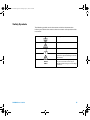
Safety Symbols
The following symbols on the instrument and in the documentation
indicate precautions that must be taken to maintain safe operation of the
instrument.
Earth (ground) terminal
Caution, risk of electric shock
Frame or chassis terminal
Caution, risk of danger (refer to this
manual for specific Warning or Caution
information)
CAT II
300 V
34450A User’s Guide
IEC Measurement Category II. Inputs
may be connected to mains (up to
300 VAC) under Category II overvoltage
conditions.
III
34450A UG.book Page IV Tuesday, July 23, 2013 2:43 PM
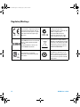
Regulatory Markings
IV
The CE mark is a registered trademark
of the European Community. This CE
mark shows that the product complies
with all the relevant European Legal
Directives.
The C-tick mark is a registered
trademark of the Spectrum
Management Agency of Australia. This
signifies compliance with
the Australia EMC Framework
regulations under the terms of the
Radio Communication Act of 1992.
ICES/NMB-001 indicates that this ISM
device complies with the Canadian
ICES-001.
Cet appareil ISM est confomre a la
norme NMB-001 du Canada.
This instrument complies with the
WEEE Directive (2002/96/EC) marking
requirement. This affixed product label
indicates that you must not discard
this electrical/electronic product in
domestic household waste.
The CSA mark is a registered
trademark of the Canadian Standards
Association.
This symbol indicates the time period
during which no hazardous or toxic
substance elements are expected to
leak or deteriorate during normal use.
Forty years is the expected useful life
of the product.
34450A User’s Guide
34450A UG.book Page V Tuesday, July 23, 2013 2:43 PM
General Safety Information
The following general safety precautions must be observed during all
phases of operation, service, and repair of this instrument. Failure to
comply with these precautions or with specific warnings elsewhere in this
manual violates safety standards of design, manufacture, and intended
use of the instrument. Agilent Technologies assumes no liability for the
customer’s failure to comply with these requirements.
WA R N I N G
34450A User’s Guide
• Do not defeat the power cord safety ground feature. Plug in to a grounded
(earthed) outlet.
• Do not use the instrument in any manner that is not specified by the
manufacturer.
• To avoid electric shock or injury, do not operate the multimeter without panels or
case in place.
• Do not substitute parts or modify the instrument to avoid the danger of
introducing additional hazards. Return the instrument to Agilent Technologies
Sales and Service Office for service and repair to ensure the safety features are
maintained.
• Main Power and Test Input Disconnect: Unplug the instrument from the wall
outlet, remove the power cord, and remove all probes from all terminals before
servicing. Only qualified, service-trained personnel should remove the cover from
the instrument.
• Line and Current Protection Fuses: For continued protection against fire, replace
the line fuse and the current-protection fuse only with fuses of the specified type
and rating.
• IEC Measurement Category II. The HI and LO input terminals may be connected to
mains in IEC Category II installations for line voltages up to 300 VAC. To avoid the
danger of electric shock, do not connect the inputs to mains for line voltages
above 300 VAC. See “IEC Measurement Category II Overvoltage Protection” on
the following page for further information.
• Protection limits: To avoid instrument damage and the risk of electric shock, do
not exceed any of the Protection Limits defined in the following section.
• If the Test Lead Set is used in a manner not specified by Agilent Technologies, the
protection provided by the Test Lead Set may be impaired. Also, do not use a
damaged or worn Test Lead Set. Instrument damage or personal injury may
result.
V
34450A UG.book Page VI Tuesday, July 23, 2013 2:43 PM
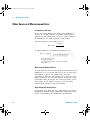
Protection Limits
The Agilent 34450A 5½ Digital Multimeter
provides protection circuitry to prevent
damage to the instrument and to protect
against the danger of electric shock, provided that the Protection Limits are not
exceeded. To ensure safe operation of the
instrument, do not exceed the Protection
Limits shown on the front panel, as defined
below:
E
A
B
C
D
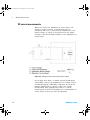
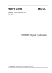
Note: The front-panel terminals and current
protection fuse are shown above.
Input Terminal Protection
Limits
Protection Limits are defined for the input
terminals:
Main Input (HI and LO) Terminals. The HI
and LO input terminals are used for voltage,
resistance, capacitance, and diode test
measurements. Two Protection Limits are
defined for these terminals:
HI to LO Protection Limit. The Protection
Limit from HI to LO ("A" in the figure
above) is 1000 VDC or 750 VAC, which is
also the maximum voltage measurement.
This limit can also be expressed as
1000 Vpk maximum.
VI
LO to Ground Protection Limit. The LO
input terminal can safely "float" a maximum of 500 Vpk relative to ground. This is
Protection Limit "B" in the figure.
Although not shown on the figure, the Protection Limit for the HI terminal is a maximum of 1000 Vpk relative to the ground.
Therefore, the sum of the “float” voltage
and the measured voltage must not exceed
1000 Vpk
Current Input Terminal. The current input
("I") terminal has a Protection Limit of
100 mA (rms) maximum current flowing
from the LO input terminal. This is Protection Limit "C" in the figure. Note that the
current input terminal will be at approximately the same voltage as the LO terminal.
Note: The current-protection circuitry
includes a fuse on the back panel. To maintain protection, replace this fuse only with a
fuse of the specified type and rating.
10 A Current Input Terminal. The 10 A current input terminal has a Protection Limit of
10 A (rms) maximum current flowing from
the LO input terminal. This is Protection
Limit "D" in the figure. Note that the current
input terminal will be at approximately the
same voltage as the LO terminal.
Note: The current-protection circuitry
includes an internal fuse. To maintain protection, service-trained personnel should
replace this fuse only with a fuse of the
specified type and rating.
Sense Terminal Protection
Limits
The HI and LO sense terminals are used
only for four-wire resistance measurements
(" Ω 4W"). The Protection Limit is 200 Vpk
for all of the terminal pairings ("E" in the figure):
LO sense to LO input.
HI sense to LO input.
HI sense to LO sense.
Note: The 200 Vpk limit on the sense terminals is the Protection Limit. Operational
voltages in resistance measurements aremuch lower - less than 5 V in normal operation.
IEC Measurement Category II
Overvoltage Protection
To protect against the danger of electric
shock, the Agilent 34450A 5½ Digital Multimeter provides overvoltage protection for
line-voltage mains connections meeting
both of the following conditions:
The HI and LO input terminals are connected to the mains under Measurement
Category II conditions, defined below, and
The mains are limited to a maximum line
voltage of 300 VAC.
IEC Measurement Category II includes electrical devices connected to mains at an outlet on a branch circuit. Such devices include
most small appliances, test equipment, and
other devices that plug into a branch outlet
or socket. The 34450A may be used to make
measurements with the HI and LO inputs
connected to mains in such devices, or to
the branch outlet itself (up to 300 VAC).
However, the 34450A may not be used with
its HI and LO inputs connected to mains in
permanently installed electrical devices
such as the main circuit-breaker panel,
sub-panel disconnect boxes, or permanently
wired motors. Such devices and circuits are
subject to overvoltages that may exceed the
protection limits of the 34450A.
Note: Voltages above 300 VAC may be measured only in circuits that are isolated from
mains. However, transient overvoltages are
also present on circuits that are isolated
from mains. The 34450A is designed to
safely withstand occasional transient overvoltages up to 2500 Vpk. Do not use this
multimeter to measure circuits where transient overvoltages could exceed this level.
34450A User’s Guide
34450A UG.book Page VII Tuesday, July 23, 2013 2:43 PM
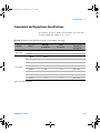
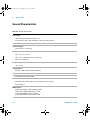
Environmental Conditions
This instrument is designed for indoor use and in an area with low
condensation. The table below shows the general environmental
requirements for the instrument.
NOTE
34450A User’s Guide
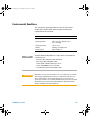
Requirement
Operating temperature
Full accuracy at 0 °C to 55 °C
Operating humidity
Full accuracy up to 80% RH at 30 °C
(non-condensing)
Storage temperature
–40 °C to 70 °C
Altitude
Operating up to 3,000 meters
Pollution degree
Pollution Degree 2
The Agilent 34450A 5½ Digit Multimeter complies with the following EMC and
safety requirements:
•
•
•
•
•
CAUTION
Environmental Condition
IEC 61010-1:2001 / EN 61010-1:2001 (2nd Edition)
IEC 61326-2-1:2005 / EN61326-2-1:2006
CISPR 11:2003 / EN 55011:2007 Group 1 Class A
Canada: ICES/NMB-001:Issue 4, June 2006
Australia/New Zealand: AS/NZS CISPR 11:2004
Degradation of some product specifications can occur in the presence of ambient
electromagnetic (EM) fields and noise that are coupled to the power line or I/O
cables of the instrument. The instrument will self-recover and operate to all
specifications when the source of ambient EM field and noise are removed or when
the instrument is protected from the ambient EM field or when the instrument
cabling is shielded from the ambient EM noise.
VII
34450A UG.book Page VIII Tuesday, July 23, 2013 2:43 PM
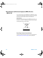
Waste Electrical and Electronic Equipment (WEEE) Directive
2002/96/EC
This instrument complies with the WEEE Directive (2002/96/EC) marking
requirement. This affixed product label indicates that you must not discard
this electrical/electronic product in domestic household waste.
Product Category:
With reference to the equipment types in the WEEE directive Annex 1, this
instrument is classified as a “Monitoring and Control Instrument” product.
The affixed product label is shown as below:
Do not dispose in domestic household waste
To return this unwanted instrument, contact your nearest Agilent office, or
visit www.agilent.com/environment/product for more information.
VIII
34450A User’s Guide
34450A UG.book Page IX Tuesday, July 23, 2013 2:43 PM
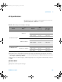
Additional Notices
The Agilent 34450A is provided with an Agilent 34138A Test Lead Set,
described below.
Test Lead Ratings
Test Leads - 1000 V, 15 A
Fine Tip Probe Attachments - 300 V, 3 A
Mini Grabber Attachment - 300 V, 3 A
SMT Grabber Attachments - 300 V, 3 A
Operation
The Fine Tip, Mini Grabber, and SMT Grabber attachments plug onto the
probe end of the Test Leads.
Maintenance
If any portion of the Test Lead Set is worn or damaged, do not use. Replace
with a new Agilent 34138A Test Lead Set.
WA R N I N G
34450A User’s Guide
If the Test Lead Set is used in a manner not specified by Agilent Technologies, the
protection provided by the Test Lead Set may be impaired. Also, do not use a
damaged or worn Test Lead Set. Instrument damage or personal injury may result.
IX
34450A UG.book Page X Tuesday, July 23, 2013 2:43 PM
Declaration of Conformity (DoC)
The Declaration of Conformity (DoC) for this instrument is available on the
Web site. You can search the DoC by its product model or description.
http://regulations.corporate.agilent.com/DoC/search.htm
NOTE
X
If you are unable to search for the respective DoC, please contact your
local Agilent representative.
34450A User’s Guide
34450A UG.book Page XI Tuesday, July 23, 2013 2:43 PM
In This Guide…
This guide contains information to install the Agilent 34450A
5½ Digit Multimeter.
1
Getting Started Tutorial
This chapter provides a quick tutorial showing you how to
get started and use the front panel in order to make
measurements.
2
Functions and Features
This chapter contains information on the functions and
features of the multimeter and how to use the front panel to
operate these settings.
3
Measurement Tutorial
The Agilent 34450A multimeter is capable of making very
accurate measurements. In order to achieve the greatest
degree of accuracy, you must take the necessary steps to
eliminate potential measurement errors. This chapter
describes the common errors found in measurements and
gives suggestions on what you can do to avoid these errors.
4
Specifications
This chapter describes the Agilent 34450A 5½ Digit
Multimeter’s specifications and operating specifications
34450A User’s Guide
XI
34450A UG.book Page XII Tuesday, July 23, 2013 2:43 PM
THIS PAGE HAS BEEN INTENTIONALLY LEFT BLANK.
XII
34450A User’s Guide
34450A UG.book Page XIII Tuesday, July 23, 2013 2:43 PM
Contents
Figures
Tables
1
XVII
XIX
Getting Started Tutorial
1
The Front Panel at a Glance 2
The display at a glance 3
Single display screen 3
Dual display screen 3
The Keypad at a Glance
Feature Upgrades
6
9
The Rear Panel at a Glance
10
Making Measurements 11
Using the keys 11
Digit masking 12
Selecting current input terminals and measurement range
Measuring AC (RMS) or DC voltage 13
Measuring resistance 15
Measuring AC (RMS) or DC current up to 100 mA 16
Measuring AC (RMS) or DC current up to 10 A 17
Measuring frequency for voltage 18
Measuring frequency for current 19
Testing continuity 20
Checking diodes 21
Measuring temperature 22
Measuring capacitance 23
34450A User’s Guide
13
XIII
34450A UG.book Page XIV Tuesday, July 23, 2013 2:43 PM
Contents
Selecting a Range
24
Remote Operation 25
USB interface 25
Serial interface 26
GPIB IEEE-488 (Optional)
Code compatibility mode
SCPI commands 28
2
Functions and Features
27
28
31
Math Operations 32
Null measurement 33
Hold measurement 35
Limit measurement 36
Accessing math menu 37
Editing single statistics 38
Editing all statistics 39
Editing dB measurement 40
Editing dBm measurement 41
Math annunciators 42
Editing math functions reference values
Editing values 43
The Dual Display 44
Using the dual display
42
45
Using the Utility Menu 47
RS232 utility sub-menu 51
GPIB Utility Sub-Menu 53
Reading error messages 54
The beeper 55
Storing and Recalling Instrument States
Reset/Power-On State
Triggering the Multimeter
XIV
56
58
60
34450A User’s Guide
34450A UG.book Page XV Tuesday, July 23, 2013 2:43 PM
Contents
Data Logging 65
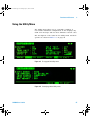
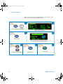
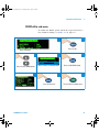
Viewing the log info 69
Viewing the log list 70
Viewing the log histogram 71
Viewing the log statistics 72
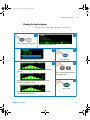
Fluke 45/Fluke 8808A Code Compatibility Mode 73
Enabling the code compatibility function 73
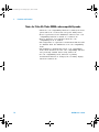
Notes for Fluke 45/Fluke 8808A code compatibility mode
3
Measurement Tutorial
75
DC Measurement Considerations
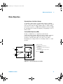
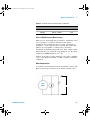
Noise Rejection
74
76
77
Measurement Speed Consideration
80
Dual Measurement Considerations 81
DC voltage dynamic range in dual measurement
Voltage and current in dual measurement 82
Resistance Measurement Considerations
True RMS AC Measurements
81
84
87
Other Primary Measurement Functions 91
Frequency measurement errors 91
DC current measurements 92
Capacitance measurements 93
Temperature measurements 95
Other Sources of Measurement Error
4
Specifications
99
Test Considerations
34450A User’s Guide
96
100
DC Specifications
101
AC Specifications
103
XV
34450A UG.book Page XVI Tuesday, July 23, 2013 2:43 PM
Contents
Temperature and Capacitance Specifications
Operating Specifications 106
Supplemental measurement specifications
105
108
General Characteristics 112
To calculate total measurement error 114
Accuracy specifications 115
Configuring for highest accuracy measurements
XVI
116
34450A User’s Guide
34450A UG.book Page XVII Tuesday, July 23, 2013 2:43 PM
Figures
Figure 1-1
Figure 1-2
Figure 1-3
Figure 1-4
Figure 1-5
Figure 1-6
Figure 1-7
Figure 1-8
Figure 1-9
34450A front panel 2
Typical single display screen 3
Typical dual display screen 3
34450A Keypad 6
Rear panel at a glance 10
ACV rms and DCV terminal connection and display 14
2-wire W terminal connection and display 15
4-wire W terminal connection and display 15
ACI rms or DCI (mA) terminal connection and
display 16
Figure 1-10 ACI rms or DCI (A) terminal connection and
display 17
Figure 1-11 Frequency terminal connection and display 18
Figure 1-12 Frequency terminal connection and display for ACI
(mA) 19
Figure 1-13 Frequency terminal connection and display for ACI
(A) 19
Figure 1-14 Continuity test terminal connection and display 20
Figure 1-15 Forward-biased diode terminal connection and
display 21
Figure 1-16 Reverse-biased diode terminal connection and
display 21
Figure 1-17 Temperature terminal connection and display 22
Figure 1-18 Capacitance terminal connection and display 23
Figure 1-19 Serial interface connector diagram 27
Figure 2-1 Accessing the null measurement 34
Figure 2-2 Accessing hold measurement 35
Figure 2-3 First page of the Utility menu 47
Figure 2-4 Second page of the Utility menu 47
34450A User’s Guide
XVII
34450A UG.book Page XVIII Tuesday, July 23, 2013 2:43 PM
Figures
Figure 2-5
Figure 2-6
Figure 3-1
Figure 3-2
Figure 3-3
Figure 3-4
Trigger in connector 62
Trigger out connector 63
Common Mode Rejection (CMR) 77
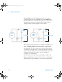
Noise caused by ground loops 79
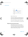
ADC Dynamic Range 82
Example of measuring voltage and current in dual
measurement 83
Figure 3-5 Wiring resistance and current shunt resistance 92
Figure 3-6 Applying current to the capacitor 93
XVIII
34450A User’s Guide
34450A UG.book Page XIX Tuesday, July 23, 2013 2:43 PM
Tables
Table 1-1
Table 1-2
Table 1-3
Table 2-1
Table 2-2
Table 2-3
Table 2-4
Table 2-5
Table 2-6
Table 2-7
Table 2-8
Table 3-1
Display annunciators 4
Keypad functions 6
License details 9
Math operations 32
Math value annunciators 42
Measurements available in dual display mode 44
Measurement operation frequencies for DCV-ACI 45
Utility menu available settings 48
RS232 utility sub-menu 52
Reset/Power-on state 58
Data log menu options 67
Common thermoelectric voltages for connections
between dissimilar metals 76
Table 3-2 Examples of measurement ranges 84
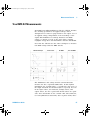
Table 3-3 Typical errors for various pulse waveforms as a function
of input pulse frequency 89
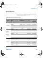
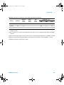
Table 4-1 DC accuracy ± (% of reading + % of range) 101
Table 4-2 AC accuracy ± (% of reading + % of range) 103
Table 4-3 Frequency accuracy ± (% of reading + count) 104
Table 4-4 Frequency resolution 104
Table 4-5 Temperature and capacitance accuracy ± (% of reading +
% of range) 105
Table 4-6 Operating specifications on single display
(approximate) 106
Table 4-7 Supplemental measurement specifications 108
Table 4-8 General characteristics 112
34450A User’s Guide
XIX
34450A UG.book Page XX Tuesday, July 23, 2013 2:43 PM
Tables
THIS PAGE HAS BEEN INTENTIONALLY LEFT BLANK.
XX
34450A User’s Guide
34450A UG.book Page 1 Tuesday, July 23, 2013 2:43 PM
Agilent 34450A 5½ Digit Multimeter
User’s Guide
1
Getting Started Tutorial
The Front Panel at a Glance 2
The Keypad at a Glance 6
The Rear Panel at a Glance 10
Feature Upgrades 9
Making Measurements 11
Selecting a Range 24
Remote Operation 25
This chapter provides a tutorial on how to get started using
the Agilent 34450A 5½ Digit Multimeter and using the front
panel in order to make measurements.
Agilent Technologies
1
34450A UG.book Page 2 Tuesday, July 23, 2013 2:43 PM
1
Getting Started Tutorial
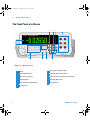
The Front Panel at a Glance
10
7
9
11
1
4
2
3
6
5
8
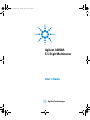
Figure 1-1 34450A front panel
2
1
Display
7
Auto range and Manual range
2
Power ON/OFF Switch
8
Resolution, Measurement Speed
3
Measurement functions
9
SHIFT (selects blue shifted keys) and Local Key
4
Math Operations
10
Secondary Display Key
5
State Store/Recall, Utility Menu
11
Input Terminals
6
Data Log, View
34450A User’s Guide
34450A UG.book Page 3 Tuesday, July 23, 2013 2:43 PM
Getting Started Tutorial
1
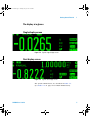
The display at a glance
Single display screen
Figure 1-2 Typical single display screen
Dual display screen
Figure 1-3 Typical dual display screen
The system annunciators are described in Table 1- 1.
(See Table 2- 2 on page 42 for Math Annunciators).
34450A User’s Guide
3
34450A UG.book Page 4 Tuesday, July 23, 2013 2:43 PM
1
Getting Started Tutorial
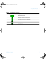
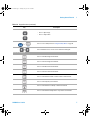
Table 1-1 Display annunciators
System Annunciator
Description
Sample annunciator - indicates readings being taken
The keypad has been locked. Press the
more than 3 seconds to unlock
keys simultaneously for
Fixed range is selected for primary function
Auto-ranging is selected for primary function
Data logging is in progress
High input impedance is configured for DCV function
2-wire resistance function is enabled
4-wire resistance function is enabled
Diode test function is enabled
Capacitance function is enabled
Continuity test function is enabled
Error in queue
Fast speed is selected
Medium speed is selected
Slow speed is selected
Remote interface operation
Code compatibility mode
2nd key has been pressed
Triggering has been enabled and the meter is in the “waiting-for-trigger” state
4
34450A User’s Guide
34450A UG.book Page 5 Tuesday, July 23, 2013 2:43 PM
Getting Started Tutorial
1
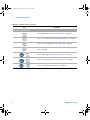
Table 1-1 Display annunciators (continued)
System Annunciator
Description
Shift key has been pressed
Fixed range is selected for secondary function
Auto-ranging is selected for secondary function
Direct current
Alternating current
34450A User’s Guide
5
34450A UG.book Page 6 Tuesday, July 23, 2013 2:43 PM
1
Getting Started Tutorial
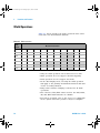
The Keypad at a Glance
The operation for each key is shown in Table 1- 2 below.
Pressing a measurement function key changes the current
key operation, brings up the relevant symbol on the display
(see “The display at a glance” on page 3), and emits a beep.
Figure 1-4 34450A Keypad
Table 1-2 Keypad functions
Key
Description
System-related operation
Press to turn ON or turn OFF the 34450A multimeter
Press to enable access to a button’s alternate function
Press to enable the secondary display
>
6
Press to disable secondary display
•
Press to adjust the measurement speed and resolution
•
Press to navigate menus
34450A User’s Guide
34450A UG.book Page 7 Tuesday, July 23, 2013 2:43 PM
Getting Started Tutorial
1
Table 1-2 Keypad functions (continued)
Key
>
Description
•
Press to adjust range
•
Press to adjust values
Press to access utility menu. See “Using the Utility Menu” on page 47
Press simultaneous for 3 seconds to lock and unlock the keypad
Measurement functions
Press to select DC voltage measurement
Press to select AC voltage measurement
Press to select DC current measurement
Press to select AC current measurement
Press to select between 2-wire or 4-wire resistance measurement
Press to select frequency measurement
Press to select between continuity or diode measurement
Press to select between temperature or capacitance measurement
34450A User’s Guide
7
34450A UG.book Page 8 Tuesday, July 23, 2013 2:43 PM
1
Getting Started Tutorial
Table 1-2 Keypad functions (continued)
Key
Description
Measurement - related functions
Press to enable null function. See “Null measurement” on page 33
Press to access math functions menu. See “Math Operations” on page 32
Press to access data logging menu. See “Data Logging” on page 65
Press to access store/recall menu. See “Storing and Recalling Instrument
States” on page 56
8
>
Press to enable trigger/hold. See “Hold measurement” on page 35
>
Press to access limit function. See “Limit measurement” on page 36
>
Press to access data log view menu. See “” on page 68
34450A User’s Guide
34450A UG.book Page 9 Tuesday, July 23, 2013 2:43 PM
Getting Started Tutorial
1
Feature Upgrades
There are two licenses, listed in Table 1- 3, which are
available for purchase:
Table 1-3 License details
Default Factory Settings
With Purchase of License
Part Number
Data Logging Memory
5,000 readings
50,000 readings (Option 3445MEMU) 34450A-801
GPIB Remote Operation
Disabled
Enabled (Option 3445GPBU)
34450A-800
For the license upgrade procedure, refer to the instructions
in the license redemption e- mail.
34450A User’s Guide
9
34450A UG.book Page 10 Tuesday, July 23, 2013 2:43 PM
1
Getting Started Tutorial
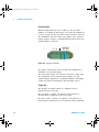
The Rear Panel at a Glance
3
4
1
2
6
5
10
7
7
8
9
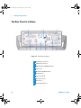
Figure 1-5 Rear panel at a glance
1
Serial Interface Connector
2
USB Interface Connector
3
GPIB with Option 3445GPBU installed
4
Current Fuse
5
Model and Serial Number Label
6
Kensington Lock
7
Chassis Ground Lug
8
AC Power Connector
9
AC Line Fuse
10 AC Line Voltage Selector
10
34450A User’s Guide
34450A UG.book Page 11 Tuesday, July 23, 2013 2:43 PM
Getting Started Tutorial
1
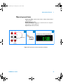
Making Measurements
The following pages show how to make measurement
connections and how to select measurement functions from
the front panel for each of the measurement functions.
For remote operation, refer to the MEASure Subsystem in
the Agilent 34450A Online Programmer’s Reference Helpfile.
Using the keys
The meter functions and operations can be selected by
pressing the buttons located on the front panel; see “The
Keypad at a Glance” on page 6. There are different ways in
which the buttons are used to select the functions and
operations. The ways to use the buttons are shown below:
>
Single press
34450A User’s Guide
Press one button after another
Press twice
11
34450A UG.book Page 12 Tuesday, July 23, 2013 2:43 PM
1
Getting Started Tutorial
Digit masking
The navigation keypad provides a shortcut to mask (change
the number of digits displayed) the reading on the main
display, easing readability. Masking digits only affects what
is displayed. It does not affect measurement speed or
accuracy. It applies to all functions except continuity, diode
test, temperature, and capacitance measurement. To enable
masking, follow the instructions below:
1
O
>
or
Press to enable digit mask feature
3
Digit mask display screen
5
4
Select desired settings
12
Press to execute
34450A User’s Guide
34450A UG.book Page 13 Tuesday, July 23, 2013 2:43 PM
Getting Started Tutorial
1
Selecting current input terminals and measurement range
If AC or DC current is being measured in auto- ranging
mode, with a signal input at 100 mA, the meter will select
the range 100 µA to 100 mA automatically.
If a signal input is applied to the 10 A input terminal, the
meter will select the 1 A to 10 A range automatically.
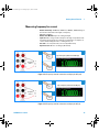
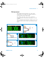
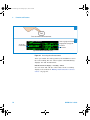
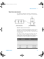
Measuring AC (RMS) or DC voltage
AC Voltage:
•
•
•
•
Measurement Range: 100.000 mV, 1.00000 V, 10.0000 V, 100.000 V, 750.00 V
Speed: Slow-2 Hz, Medium-20 Hz, Fast-200 Hz
Default Setting: Autoranging, Slow measurement speed
Measurement Method: AC coupled true RMS - measures the AC component
with up to 400 VDC bias on any range
• Crest Factor: Maximum 3:1 at full scale
• Input Impedance: 1 MΩ ± 2% in parallel with <100 pF on all ranges
• Input Protection: 750 V rms on all ranges (HI terminal)
DC Voltage:
•
•
•
•
•
Measurement Range: 100.000 mV, 1.00000 V, 10.0000 V, 100.000 V, 1000.00 V
Speed: Slow, Medium, Fast
Default Setting: Autoranging, Slow measurement speed
Measurement Method: Sigma Delta A-to-D converter
Input Impedance: >10 GΩ selected range (0.1 V and 1 V only) or ~10 MΩ all
ranges (typical)
• Input Protection: 1000 V on all ranges (HI terminal)
34450A User’s Guide
13
34450A UG.book Page 14 Tuesday, July 23, 2013 2:43 PM
1
Getting Started Tutorial
1
2-a
Typical ACV Measurement Display
3-a
AC or DC
voltage source
2-b
Typical DCV Measurement Display
3-b
Figure 1-6 ACV rms and DCV terminal connection and display
WA R N I N G
14
Do not apply any voltage to the instrument inputs until all terminals
are properly connected. Plugging or unplugging the test lead while
high voltage is applied can cause instrument damage, and may
increase the risk of electric shock.
34450A User’s Guide
34450A UG.book Page 15 Tuesday, July 23, 2013 2:43 PM
Getting Started Tutorial
1
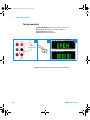
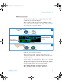
Measuring resistance
• Measurement Range: 100.000 Ω,, 1.00000 kΩ,, 10.0000 kΩ,, 100.000 kΩ,
1.00000 MΩ, 10.0000 MΩ, 100.000 MΩ.
• Speed: Slow, Medium, Fast
• Default Setting: Autoranging, Slow measurement speed
• Measurement Method: 2-wire ohms or 4-wire ohms
• Input protection: 1000 V on all ranges (HI terminal)
I
2-Wire
Ω,
1
3
2
Typical Resistance Measurement Display
Resistance
Figure 1-7 2-wire Ω terminal connection and display
1
I
4-Wire
Ω,
3
2
Typical Resistance Measurement Display
Resistance
Resistance
Press Twice
Press Twice
Figure 1-8 4-wire Ω terminal connection and display
34450A User’s Guide
15
34450A UG.book Page 16 Tuesday, July 23, 2013 2:43 PM
1
Getting Started Tutorial
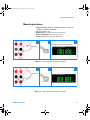
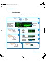
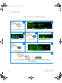
Measuring AC (RMS) or DC current up to 100 mA
•
•
•
•
•
•
Measurement Range (AC): 10.0000 mA, 100.000 mA
Measurement Range (DC): 100.000 µA, 1.00000 mA, 10.0000 mA, 100.000 mA
Speed (AC): Slow-2 Hz, Medium-20 Hz, Fast-200 Hz
Speed (DC): Slow, Medium, Fast
Default Setting: Autoranging, Slow measurement speed
Shunt Resistance: 1 Ω for 10 mA and 100 mA, and 90 Ω for 100 µA to 1 mA
ranges
• Input Protection: Rear Panel 0.4 A, 500 V FH fuse for the I terminal
1
AC or DC
current source
2-a
Typical ACI Measurement Display
3-a
2-b
Typical DCI Measurement Display
3-b
Figure 1-9 ACI rms or DCI (mA) terminal connection and display
16
34450A User’s Guide
34450A UG.book Page 17 Tuesday, July 23, 2013 2:43 PM
Getting Started Tutorial
1
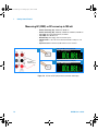
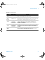
Measuring AC (RMS) or DC current up to 10 A
•
•
•
•
•
•
•
1
AC or DC
Voltage Source
Measurement Range (AC): 1.00000 A, 10.0000 A
Measurement Range (DC): 1.00000 A, 10.0000 A
Speed (AC): Slow-2 Hz, Medium-20 Hz, Fast-200 Hz
Speed (DC): Slow, Medium, Fast
Default Setting: Autoranging, Slow measurement speed
Shunt Resistance: 0.01 Ω for 1 A and 10 A range
Input Protection: Internal 11 A, 1000 V fuse for the 10 A terminal
2-a
Typical ACI Measurement Display
3-a
2-b
Typical DCI Measurement Display
3-b
Figure 1-10 ACI rms or DCI (A) terminal connection and display
34450A User’s Guide
17
34450A UG.book Page 18 Tuesday, July 23, 2013 2:43 PM
1
Getting Started Tutorial
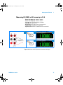
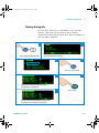
Measuring frequency for voltage
• Measurement Range: 100.000 mV, 1.00000 V, 10.0000 V, 100.000 V, 750.00 V.
Range is based on the voltage level of the signal, not frequency.
• Speed: Slow, Medium
• Measurement Method: Reciprocal counting technique
• Signal level: 10% of range to full scale input on all ranges except where noted.
100 mV range specifications are for full scale or greater inputs. For inputs from
10 mV to 100 mV, multiply the total % of reading error by 10.
• Gate Time: 1 second (slow mode) or 0.1 second (medium mode)
• Input Protection: 750 V rms on all ranges (HI terminal)
1
4
2
Typical Frequency Measurement Display
Frequency
Source
3
Figure 1-11 Frequency terminal connection and display
18
34450A User’s Guide
34450A UG.book Page 19 Tuesday, July 23, 2013 2:43 PM
Getting Started Tutorial
1
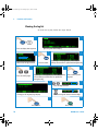
Measuring frequency for current
• Measurement Range: 10.0000 mA, 100.000 mA, 1.00000 A, 10.0000 A. Range is
based on the current level of the signal, not frequency.
• Speed: Slow, Medium
• Measurement Method: Reciprocal counting technique
• Signal level: 10% of range to full scale input on all ranges except where noted.
10 mA range specifications are for full scale or greater inputs. For inputs from
1 mA to 10 mA, multiply the total % of reading error by 10.
• Gate Time: 1 second (slow mode) or 0.1 second (medium mode)
• Input Protection: 750 V rms on all ranges (HI terminal)
1
4
2
Typical Frequency Measurement Display
Frequency
Source
3
Figure 1-12 Frequency terminal connection and display for ACI (mA)
1
4
2
Typical Frequency Measurement Display
Frequency
Source
3
Figure 1-13 Frequency terminal connection and display for ACI (A)
34450A User’s Guide
19
34450A UG.book Page 20 Tuesday, July 23, 2013 2:43 PM
1
Getting Started Tutorial
Testing continuity
•
•
•
•
I
Measurement Method: 0.5 mA ± 0.2% constant current source
Response Time: 165 samples/second with audible tone
Continuity Threshold: 10 Ω fixed
Input Protection: 1000 V (HI terminal)
1
2
Open Circuit Measurement Display
3
Open or
Closed Circuit
Typical Closed Circuit Measurement Display
Figure 1-14 Continuity test terminal connection and display
20
34450A User’s Guide
34450A UG.book Page 21 Tuesday, July 23, 2013 2:43 PM
Getting Started Tutorial
1
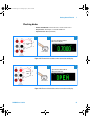
Checking diodes
• Measurement Method: Uses 0.5 mA ± 0.2% constant current source
• Response Time: 190 samples/ second with audible tone
• Input Protection: 1000 V (HI terminal)
I
1
3
2
Typical Forward-Biased Diode
Measurement Display
Forward
Bias
Press Twice
Figure 1-15 Forward-biased diode terminal connection and display
I
1
3
2
Typical Reverse-Biased Diode
Measurement Display
Reverse
Bias
Press Twice
Figure 1-16 Reverse-biased diode terminal connection and display
34450A User’s Guide
21
34450A UG.book Page 22 Tuesday, July 23, 2013 2:43 PM
1
Getting Started Tutorial
Measuring temperature
• Measurement Range: –80.0 °C to 150.0 °C, –110.0 °F to 300.0 °F
• Measurement Method: 2-wire Ohms measurement of 5 kΩ thermistor sensor
(E2308A) with computed conversion
• Input Protection: 1000 V (HI terminal)
• Optional Accessory: E2308A Thermistor temperature probe
1
3
2
I
5kΩ,
Thermistor
Typical Temperature Measurement Display
Figure 1-17 Temperature terminal connection and display
22
34450A User’s Guide
34450A UG.book Page 23 Tuesday, July 23, 2013 2:43 PM
Getting Started Tutorial
1
Measuring capacitance
• Measurement Range: 1.000 nF, 10.00 nF, 100.0 nF, 1.000 µF, 10.00 µF, 100.0 µF,
1.000 mF, 10.00 mF
• Default Setting: Autoranging
• Measurement Method: Computed from constant current source charge time.
Typical 0.12 V to 1.0 V AC signal level
• Input Protection: 1000 V (HI terminal)
1
3
2
Typical Capacitance Measurement Display
Capacitance
Press Twice
Figure 1-18 Capacitance terminal connection and display
34450A User’s Guide
23
34450A UG.book Page 24 Tuesday, July 23, 2013 2:43 PM
1
Getting Started Tutorial
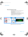
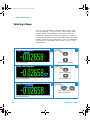
Selecting a Range
You can let the multimeter automatically select the range
using autoranging, or you can select a fixed range using
manual ranging. Autoranging is convenient because the
multimeter automatically selects the appropriate range for
sensing and displaying each measurement. However, manual
ranging results in better performance, since the multimeter
does not have to determine which range to use for each
measurement.
2
1
Autoranging enabled
Press to disable autoranging
3
4
Selects an upper range
Selects a lower range
Manual ranging enabled
6
5
>
Press to enable autoranging and
disable manual ranging
Manual ranging enabled
24
34450A User’s Guide
34450A UG.book Page 25 Tuesday, July 23, 2013 2:43 PM
Getting Started Tutorial
1
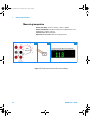
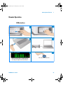
Remote Operation
USB interface
Automatically shows the remote state
when communication is established after
executing the Agilent Connection Expert
34450A User’s Guide
1
2
3
4
5
6
Press to exit Remote state
25
34450A UG.book Page 26 Tuesday, July 23, 2013 2:43 PM
1
Getting Started Tutorial
NOTE
To easily configure and verify an interface connection between the 34450A and your PC,
use the Automation- Ready CD, which is shipped with your 34450A. This CD includes the
Agilent IO Libraries Suite and the Agilent Connection Expert application. For more
information about Agilent's I/O connectivity software, visit www.agilent.com/find/iolib.
Serial interface
NOTE
To use this serial interface, it is recommended to use the
optional Serial- to- RS232 adapter (34450A- 700)
The 5- pin male connector on the meter’s rear panel is a
serial port or terminal to form a minimal 3- wire RS- 232
connection (TX, RX, GND).
In order to operate the multimeter via a host computer or
terminal, the parameters of the serial interface within the
multimeter has to match the parameters with the serial
interface provided by the host or terminal.
The default settings of the meter are 9600 baud rate,
non- parity, 8 data bits, and 1 stop bit (9600, n, 8, 1).
26
34450A User’s Guide
34450A UG.book Page 27 Tuesday, July 23, 2013 2:43 PM
Getting Started Tutorial
1
The connecting diagram and setup procedure are shown in
“Serial interface connector diagram” and “RS232 utility
sub- menu” on page 52 below.
Serial-to-RS232 adapter (34450A-700)
Instrument
PC
1
RS232 Protocol RX
2
Yellow
GND
3
Grey
TRIGGER IN
4
TRIGGER OUT
5
Serial
Interface
Male
Serial
Interface
Female
1
2
3
4
5
6
7
8
9
Red
TX
DB9
Female
DCD
RX
TX
DTR
GND
DSR
RTS
CTS
RI
DB9
Male
Figure 1-19 Serial interface connector diagram
GPIB IEEE-488 (Optional)
The GPIB interface is a bus structure that links the
multimeter to a host computer or other GPIB controlled
instruments to form an automated measuring system.
It can be used to connect up to 15 devices on one
continuous bus, star, or linear bus network.
In order to operate the meter via a host computer or
terminal, the parameters in the GPIB interface within the
meter has to match the parameters in the GPIB interface
provided by the host or terminal.
The default factory settings are address 22.
34450A User’s Guide
27
34450A UG.book Page 28 Tuesday, July 23, 2013 2:43 PM
1
Getting Started Tutorial
Code compatibility mode
The 34450A includes a code compatibility mode. This mode
saves time and effort by eliminating the need to re- write
programs using the 34450A SCPI command.
SCPI commands
The Agilent 34450A complies with the syntax rules and
conventions of SCPI (Standard Commands for Programmable
Instruments).
NOTE
For a complete discussion of the 34450A SCPI syntax, refer to the Agilent 34450A
Programmer’s Reference Helpfile, This is provided in the 34450A Product Reference
CD-ROM
SCPI Language Version
You can determine the multimeter’s SCPI language version
by sending the SYSTem:VERSion? command from the
remote interface.
28
34450A User’s Guide
34450A UG.book Page 29 Tuesday, July 23, 2013 2:43 PM
Getting Started Tutorial
1
• You can query the SCPI version from the remote interface
only.
• The SCPI version is returned in the form “YYYY.V”,
where “YYYY” represents the year of the version, and “V”
represents a version number for that year (for example,
1994.0).
34450A User’s Guide
29
34450A UG.book Page 30 Tuesday, July 23, 2013 2:43 PM
1
30
Getting Started Tutorial
34450A User’s Guide
34450A UG.book Page 31 Tuesday, July 23, 2013 2:43 PM
Agilent 34450A 5½ Digit Multimeter
User’s Guide
2
Functions and Features
Math Operations 32
The Dual Display 44
Using the Utility Menu 47
Storing and Recalling Instrument States 56
Reset/Power-On State 58
Triggering the Multimeter 60
Data Logging 65
This chapter contains information on the functions and
features of the Agilent 34450A 5½ Digit Multimeter and how
to use the front panel to operate these settings.
Agilent Technologies
31
34450A UG.book Page 32 Tuesday, July 23, 2013 2:43 PM
2
Functions and Features
Math Operations
Table 2- 1 below describes the math operations that can be
used with each measurement function.
Table 2-1 Math operations
Math
Function
Measurement Function
DCV
ACV
DCI
ACI
Ω
FREQ
DIODE
CONT
TEMP
CAP
Null
9
9
9
9
9
9
-
-
9
9
Limit
9
9
9
9
9
9
-
-
9
9
Hold
9
9
9
9
9
9
-
-
9
9
dB
9
9
-
-
-
-
-
-
-
-
dBm
9
9
-
-
-
-
-
-
-
-
Stats
9
9
9
9
9
9
-
-
9
9
• Only one math operation can be turned- on at a time.
• Math operation does not support external triggering.
• Hold operation does not support fast mode.
• In the dual display mode, selecting the math operation
will apply to the primary measurement function and turn
off the secondary function.
• Range and resolution changing is allowed for all math
operations.
• The reference/offset/limit values used for the Null, Limit,
dB, and dBm math functions are editable.
• For remote operation, refer to the CALCulate Subsystem
in the Agilent 34450A Programmer’s Reference Helpfile.
32
34450A User’s Guide
34450A UG.book Page 33 Tuesday, July 23, 2013 2:43 PM
Functions and Features
2
Null measurement
When making null measurements, also called relative
measurement, each reading is the difference between a
stored null value and the input signal.
For example, this feature can be used to make more
accurate resistance measurements by nulling the test lead
resistance.
Before performing null measurement, eliminate offset errors
associated with test lead resistance by following the steps
below:
1
2
1Ω
3
4
Press to enable null measurement
5
6
1Ω
34450A User’s Guide
33
34450A UG.book Page 34 Tuesday, July 23, 2013 2:43 PM
2
Functions and Features
1
Press to enable null measurement
2
shows ongoing measurement,
ranging method, range and
resolution
offset value
shows null
measurement
Typical Null Measurement Display
Figure 2-1 Accessing the null measurement
After you enable the null operation, the multimeter stores
the next reading into the offset register and immediately
displays the null measurement:
Null measurement display = Reading
– Offset
You can view and edit the offset value in the secondary
display as described in “Editing math functions reference
values” on page 42.
34
34450A User’s Guide
34450A UG.book Page 35 Tuesday, July 23, 2013 2:43 PM
Functions and Features
2
Hold measurement
The hold feature allows you to capture and hold a stable
reading on the front panel display.
When a stable reading is detected, the multimeter emits a
beep (if the buzzer is enabled in the utility menu) and holds
the reading on the primary display.
1
>
Press to enable hold measurement
2
Secondary display
(present measurement
reading)
Primary display
(stable hold reading)
Typical hold function display
3
>
Press to disable hold measurement
Figure 2-2 Accessing hold measurement
When enabled, the hold operation turns on the hold
annunciator and begins evaluating readings using the rules
described below:
Primary Display = ReadingN IF Max()
– Min() ≤ 0.1% × ReadingN
The decision to update a new reading value in the primary
display is based upon the box- car moving statistics of the
present reading and the three previous readings :
Max (ReadingN ReadingN–1 ReadingN–2 ReadingN–3)
Min (ReadingN ReadingN–1 ReadingN–2 ReadingN–3)
34450A User’s Guide
35
34450A UG.book Page 36 Tuesday, July 23, 2013 2:43 PM
2
Functions and Features
Limit measurement
The limit operation allows you to perform pass/fail testing
against specified upper and lower limits.
1
>
Press to enable limit measurements
2
The upper limit must
always be greater than
the lower limit.
Otherwise, “INVALID
LIMIT” will be shown.
Shows present
measurement
Limit state
Typical limit function display
3
Press to edit
4
Choose the limit mode that you want to change
6-a
5
.
Increase/decrease the respective digit
6-b
Press to edit
Select the editable digit to the left or right
7
Press to save
36
8
Press to exit the limit operation
or edit mode
34450A User’s Guide
34450A UG.book Page 37 Tuesday, July 23, 2013 2:43 PM
Functions and Features
2
Accessing math menu
The math operation can be enabled using the following
steps:
2
1
Press to display math menu
Math menu display
34450A User’s Guide
37
34450A UG.book Page 38 Tuesday, July 23, 2013 2:43 PM
2
Functions and Features
Editing single statistics
The single statistics can be edited using the following steps:
2
1
Press to start
Select STATS (SINGLE) option
3
Statistical values
Present measurement
Typical statistics (single) display for Max reading
4
5
Press to toggle the
Max/Min/Avg/N values
Press to edit
6
Maximum reading
Minimum reading
Average of all readings
Number of readings taken
>
Note: Each time a new min or max value is stored, the multimeter
will beep once (if the buzzer is turned on in the utility menu) and the
Min or Max annunciator is briefly turned on for 1 second beside the
secondary display.
7
Press to exit
38
34450A User’s Guide
34450A UG.book Page 39 Tuesday, July 23, 2013 2:43 PM
Functions and Features
2
Editing all statistics
The all statistics in the math operation can be edited using
the following steps:
1
2
Press to start
Select STATS (ALL)
Number of readings taken
3
Maximum
reading
Present measurement
Average
reading
Minimum
reading
Note: Each time a new min or max value is stored, the multimeter will beep once (if the buzzer is
turned on in the utility menu) and the New annunciator is briefly turned on for 1 second in the
respective Min or Max box
4
Press to exit
34450A User’s Guide
39
34450A UG.book Page 40 Tuesday, July 23, 2013 2:43 PM
2
Functions and Features
Editing dB measurement
When enabled, the dB operation computes the dBm value for
the next reading, stores the dBm result into the dB Ref
register, and immediately produces the following calculation.
The first displayed reading is always precisely 000.00 dB.
dB = 10 × Log10 [(Reading2/RREF)/0.001 W]–dB Ref
2
1
Press to edit
Select dB option
3
Ongoing measurement
dB measurement
Reference value
0dB to ±120.0000 dBm
Default : RREF is 0 dBm
4
Press to exit
You can view and edit the dB reference value as described
in “Editing math functions reference values” on page 42.
40
34450A User’s Guide
34450A UG.book Page 41 Tuesday, July 23, 2013 2:43 PM
Functions and Features
2
Editing dBm measurement
The logarithmic dBm (decibels relative to one milliwatt)
scale is often used in RF signal measurements. The
multimeter’s dBm operation takes a measurement and
calculates the power delivered to a reference resistance
(typically 50, 75, or 600 Ω). The formula used for conversion
from the voltage reading is:
dBm = 10 × Log10 [(Reading2 / RREF) / 0.001 Ω ]
You can choose from several reference resistance values:
RREF = 2 Ω, 4 Ω, 8 Ω, 16 Ω, 50 Ω, 75 Ω, 93 Ω, 110 Ω, 124 Ω,
125 Ω, 135 Ω, 150 Ω, 250 Ω, 300 Ω, 500 Ω, 600 Ω, 800 Ω,
900 Ω, 1000 Ω, 1200 Ω, or 8000 Ω.
2
1
Press to start
Select dBm option
3
Ongoing measurement
dBm measurement
Reference value
4
Press to exit
You can view and select the reference value as described in
“Editing math functions reference values” on page 42.
34450A User’s Guide
41
34450A UG.book Page 42 Tuesday, July 23, 2013 2:43 PM
2
Functions and Features
Math annunciators
Table 2- 2 below shows the possible math annunciators
which can appear on the display and the editable values.
Table 2-2 Math value annunciators
Math Operation
When Viewing/Editing
Editable
Math Annunciator
Null
Offset
9
Offset Value
dBm
RREF
9
Reference R Value
dB
dB Ref
9
Reference Value
Maximum
-
Max
Minimum
-
Min
Average
-
Avg
Reading Count
-
N
HI Limit
9
High Limit
LO Limit
9
Low Limit
Statistics
Limit
Editing math functions reference values
The reference values used for the Null, Limit, dB, or dBM
math functions, can be edited when you enable the stated
function (refer to Table 2- 2 on page 42 for a list).
For remote operation, refer to the CALCulate Subsystem in
the Agilent 34450A Programmer’s Reference Helpfile.
42
34450A User’s Guide
34450A UG.book Page 43 Tuesday, July 23, 2013 2:43 PM
Functions and Features
2
Editing values
For math functions with editable values, the label “PRESS
MATH TO EDIT” will be shown at the bottom left of the
display.
To edit math values, follow the steps below:
1
2
3
4-a
Press to display null menu
Press for digit selection
4-b
Press to edit
Press to change the value of selected digit
5-b
5-a
Press to exit without save
34450A User’s Guide
Press to save the reference value
43
34450A UG.book Page 44 Tuesday, July 23, 2013 2:43 PM
2
Functions and Features
The Dual Display
Most measurement functions have predefined range or
measurement capabilities that can be displayed in the dual
measurement mode. All math operations have predefined
operations that are displayed on the dual display.
Table 2- 3 below shows the measurement functions which are
available in dual display mode.
Table 2-3 Measurements available in dual display mode[1][2][3][4][5]
Secondary Display
Primary Display
DCV
ACV
DCI
ACI
Frequency
DCV
-
9
9
9
-
ACV
9
-
9
9
9
DCI
9
9
-
-
-
ACI
9
9
-
-
9
FREQUENCY
-
9
-
9
-
[1] All specifications are ensured only under a single display.
[2] For ACI-ACV dual measurement, the ACV input signal is limited to
500,000 VxHz.
[3] For DCI-ACV dual measurement, the ACV input signal is limited to
6,000,000 V×Hz.
[4] For DCV-ACV dual measurement, the DCV input signal is limited to 500 V when
ACV input signal is in 100 mV range. The ACV input signal must be greater than
50 mV.
[5] For ACI-DCV dual measurement operation frequencies, refer to Table 2-4 on
page 45
44
34450A User’s Guide
34450A UG.book Page 45 Tuesday, July 23, 2013 2:43 PM
Functions and Features
2
Table 2-4 Measurement operation frequencies for DCV-ACI
DCV-ACI
Measurement Operation Frequency
Slow/Medium
>500 Hz (600 Hz) / n x 50 Hz (60 Hz) for <500 Hz
Fast
>10 kHz / n x 1 kHz for <10 kHz
For more information , please refer to Chapter 3,
“Measurement Speed Consideration”.
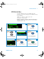
Using the dual display
To enable the dual display, follow the following steps:
34450A User’s Guide
45
34450A UG.book Page 46 Tuesday, July 23, 2013 2:43 PM
2
Functions and Features
2
1
Press to enable secondary display
Typical single display screen
4
3
Select desired secondary
measurement
Typical dual display screen
6
5
Press to control the secondary
measurement
Screen shows that secondary measurement is being controlled
8
7-a
Select desired function
for the secondary display
7-b
>
Press to turn off secondary display
Select desired range
7-c
Note: For available measurements in the
dual display mode, refer to table Table 2-3
Select desired speed
For remote operation, refer to the DISPlay:WINDow2
commands in the Agilent 34450A Programmer’s Reference
Helpfile.
46
34450A User’s Guide
34450A UG.book Page 47 Tuesday, July 23, 2013 2:43 PM
Functions and Features
2
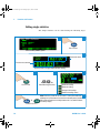
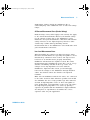
Using the Utility Menu
The Utility menu allows you to customize a number of
non- volatile instrument configurations. It also displays any
SCPI error messages and the latest firmware revision codes.
The descriptions of the items in the Utility menu and their
options are shown in Table 2- 5 on page 48
Figure 2-3 First page of the Utility menu
Figure 2-4 Second page of the Utility menu
34450A User’s Guide
47
34450A UG.book Page 48 Tuesday, July 23, 2013 2:43 PM
2
Functions and Features
Table 2-5 Utility menu available settings
Feature
BUZZER
Default
ON
Available Settings
Description
Remote Command
ON or OFF
Enables or disables Diode, Stats, Limit,
and Hold beep operations.
Turning off the buzzer does not disable
the front panel keys beep operation and
Continuity beep operation.
Refer to “The beeper” on page 55 for
more info.
SYSTem:BEEPer:STATe
• Disables or enables the GPIB, USB,
or RS232 remote interface
• If GPIB is selected, refer to “GPIB
Utility Sub-Menu” on page 53
• If RS232 is selected, refer to “RS232
utility sub-menu” on page 51
• When all I/O are disabled, DISABLE
is shown on the setting.
SYSTem:COMMunicate:
ENABle <mode>,
<interface>
I/O
USB
USB, GPIB, or
RS232
TEMP UNIT
°C
°C or °F
Selects the unit for temperature
measurements
UNIT:TEMPerature
<units>
SYSTem:LANGuage
LANGUAGE
L1
L1 or L2
L1 represents Agilent Mode
L2 represents Fluke 45/8808A Mode.
Refer to “Enabling the code
compatibility function” on page 73 for
more info.
INPUT Z
10M
10M or HIGH Z
Sets the input impedance for DCV
measurements (HIGH Z is selectable
for 100 mV and 1 V ranges only)
[SENSe:]VOLTage[:DC
]:IMPedance:AUTO
<mode>
*TST?
SELF TEST
OFF
ON or OFF
ON enables an immediate self-test of
the multimeter. Returns to normal
operation after completing the
self-test.
P-ON RESET
ON
ON or OFF
Disables or enables the automatic
recall of the powered down state when
power is turned on
MEMory:STATe:RECall
:AUTO
OCOMP
OFF
ON of OFF
Enables or disables the offset
compensation for resistance
measurement
[SENSe:]RESistance:
OCOMpe
nsated <mode>
48
34450A User’s Guide
34450A UG.book Page 49 Tuesday, July 23, 2013 2:43 PM
Functions and Features
2
Table 2-5 Utility menu available settings (continued)
CALIBRATION
SECURE
To secure or unsecure the calibration
adjustments to the instrument.
SECURE or UNSEC
Selecting it will open the [Calibration
Sub-Menu]
Feature
Default
Available Settings
CALibration:SECure:
STATe <mode>,
<code>
Description
Remote Command
BRIGHTNESS
Allows you to toggle the brightness on
the multimeter’s display
-
SCPI ERR
NONE or (Error
Message)
Available Settings; NONE or (Number
of errors)
Description; If there are errors,
selecting it will open the [SCPI Error
Sub-Menu]
SYSTem:ERRor?
XX.XX - XX.XX
Displays the multimeter’s firmware
revision. The first 4 digits are the IO
firmware revision, while the last 4
digits are the measurement firmware
revision.
-
FW VER
NONE
-
34450A User’s Guide
49
34450A UG.book Page 50 Tuesday, July 23, 2013 2:43 PM
2
Functions and Features
Below are the steps you should follow if you want to edit
any of the values on the utility menu:
2
1
>
Press to display the utility menu
Page one of utility menu
4
3
Press to edit
This option will flash, enabling you to edit
5
Select the desired value
50
7
6
Press to save
Press to exit
34450A User’s Guide
34450A UG.book Page 51 Tuesday, July 23, 2013 2:43 PM
Functions and Features
2
RS232 utility sub-menu
To enable the RS232 option, follow the steps below. For a
list of RS232 settings, see Table 2- 6 on page 52.
2
1
Press to edit
Select I/O option
3
4
5
Press to edit RS232 option
Press to select RS232 option
8
7
6
Press to edit/save
Press to return to utility menu
Typical RS232 sub menu display
34450A User’s Guide
51
34450A UG.book Page 52 Tuesday, July 23, 2013 2:43 PM
2
Functions and Features
Table 2-6 RS232 utility sub-menu
Option
52
Default
Setting
Available Settings
Description
BAUD RATE 9600
300, 600, 1200, 2400,
4800, 9600, 19200,
38400, 57600
Baud rate for remote
communication with a PC
(remote control)
PARITY
NONE
NONE, ODD, EVEN
Parity bit for remote
communication with a PC
DATA BIT
8
7, 8
Data bit length
STOP BIT
1
1, 2
Stop bit length
State
Disable
Disable, Enable
Enable or disable RS232
34450A User’s Guide
34450A UG.book Page 53 Tuesday, July 23, 2013 2:43 PM
Functions and Features
2
GPIB Utility Sub-Menu
To activate GPIB, first, turn on the GPIB option. The
following pop- up message will appear if the GPIB license key
is not activated :
“GPIB is not enabled, to enable, please visit
www.agilent.com/find/34450A”
If GPIB connectivity is selected, a sub- menu will appear to
allow you configure the address (from 0 to 30) for remote
communication to a PC.
2
1
Press to edit
Select I/O option
3
4
5
Press to edit GPIB option
Press to select GPIB option
8
7
6
Press to edit/save
Press to return to utility menu
Typical GPIB sub menu display
34450A User’s Guide
53
34450A UG.book Page 54 Tuesday, July 23, 2013 2:43 PM
2
Functions and Features
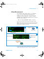
Reading error messages
To read error messages from the front panel, perform the
following procedures. For remote operation, refer to the
SYSTem:ERRor? command in the Agilent 34450A
Programmer’s Reference Helpfile.
2
1
>
Press to display the utility menu
Typical display with error message
4
3
Press to navigate to the second page
of utility menu
6
5
Press to view error
54
7
Press to exit
34450A User’s Guide
34450A UG.book Page 55 Tuesday, July 23, 2013 2:43 PM
Functions and Features
2
The beeper
Normally, the multimeter beeps whenever certain conditions
are met (for example, the multimeter beeps when a stable
reading is captured in reading hold mode).
The beeper is factory set to ON, but may be disabled or
enabled manually.
• Turning OFF the beeper does NOT disable the front panel
keys beep tones.
• A beep tone is always emitted (even with the beep state
turned OFF) in the following cases:
• A continuity measurement is less than or equal to the
continuity threshold.
• A SYSTem:BEEPer command is sent.
• An error is generated.
• In addition to the beep operations just described, when
the beeper is ON, a single beep occurs for the following
cases (turning the beeper OFF disables the beep for the
following cases):
• When a new MIN or MAX value is stored
• When a new stable reading is updated on display for
Math Hold operation
• When a measurement exceeds the HI or LO Limit value
• When a forward- biased diode is measured in the Diode
function
34450A User’s Guide
55
34450A UG.book Page 56 Tuesday, July 23, 2013 2:43 PM
2
Functions and Features
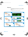
Storing and Recalling Instrument States
The present multimeter state, including all settings for
measurement configuration, math operation, and system
operations, can be saved in one of the six non- volatile
memory location and later recalled. Location LAST retains
the multimeter configuration at power down. Location LAST
and 1- 5 are available for storing the configurations.
To recall instrument states, perform the following steps:
56
34450A User’s Guide
34450A UG.book Page 57 Tuesday, July 23, 2013 2:43 PM
Functions and Features
2
1
Press to display the
store/recall menu
2
Typical store/recall display
3
Press to edit
Memory location selected
Press to select the
memory location
6
Press to save the state into
selected memory location
5
4
8
7
Display shows state is stored
9
10
Move cursor to the location
label at the recall box
Press to edit
Press to select the
memory location
12
11
Memory location selected
Press to recall state
from the selected
memory location
For remote operation, refer to the MEMory Subsystem, the
*SAV, and *RCL commands in the Agilent 34450A
Programmer’s Reference Helpfile.
34450A User’s Guide
57
34450A UG.book Page 58 Tuesday, July 23, 2013 2:43 PM
2
Functions and Features
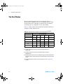
Reset/Power-On State
The table below summarizes the 34450A settings as received
from the factory, following power cycling, and following the
*RST command received over the USB remote interface.
Non- volatile, user customizable behavioral differences are
shown in BOLD.
Table 2-7 Reset/Power-on state
Parameter
Factory Setting
Power-On / Reset State
Function
DCV
DCV
Range
AUTO
AUTO
Resolution
5½ digits
5½ digits
Temperature Units
°C
User setting
Math State, Function
Off, Null
Off, Null
Math Registers
Cleared
Cleared
dBm Reference Resistance
600 Ω
User setting
Auto Trigger (Local Mode)
IMMediate (Remote Mode)
Auto Trigger (Local Mode)
IMMediate (Remote Mode)
Power-Down Recall
Disabled
User Setting
Stored States
0-5 cleared
No Change
Beeper
On
User Setting
Display
On
On
Remote/ Local State
Local
Local
Keyboard[1]
Unlocked, Local key enabled
Unlocked, Local key enabled
Measurement Configuration
Math Operations
Trigger Operation
Trigger Source [1]
System-Related Operation
58
34450A User’s Guide
34450A UG.book Page 59 Tuesday, July 23, 2013 2:43 PM
Functions and Features
2
Table 2-7 Reset/Power-on state (continued)
Parameter
Factory Setting
Power-On / Reset State
Cleared
Cleared
Cleared
Cleared if power cycle
Power-on Status Clear [1]
Enabled
User Setting
Status Registers, Masks & Transition
Filters[1]
Cleared
Cleared if power-on status clear
enabled; no change otherwise
Serial Number
Unique value per-instrument
No Change
Calibration state
Secured
User Setting
Calibration value
0
No Change
Calibration String
Cleared
No Change
Reading Output Buffer [1]
Error Queue
[1]
Calibration
[1] State managed by IO processor firmware
34450A User’s Guide
59
34450A UG.book Page 60 Tuesday, July 23, 2013 2:43 PM
2
Functions and Features
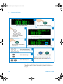
Triggering the Multimeter
At power- on, the default trigger source is auto- triggering.
Auto- triggering takes continuous readings at the fastest rate
possible for the selected measurement configuration. To
make a trigger measurement, follow the steps below:
1 Configure the multimeter for the measurement by
selecting the function, range, resolution, and so on.
2 Specify the multimeter’s trigger source. Choices are as
below:
• Software (bus) trigger from the remote interface.
• An immediate internal trigger (default trigger source).
• An external trigger from an external trigger pulse.
3 Ensure that the multimeter is ready to accept a trigger
from the specified source (called the wait- for- trigger
state).
Immediate Triggering
The immediate triggering mode is available from the remote
interface only.
In the immediate trigger mode, the trigger signal is always
present. When you place the multimeter in the
wait- for- trigger state, the trigger is issued immediately. This
is the default trigger source for remote interface operation.
• Remote Interface Operation: The following command selects
the immediate trigger source:
TRIGger:SOURce IMMediate
The CONFigure and MEASure? commands automatically
set the trigger source to IMMediate.
Refer to the Agilent 34450A Programmer’s Reference
Helpfile for complete description and syntax for these
commands.
60
34450A User’s Guide
34450A UG.book Page 61 Tuesday, July 23, 2013 2:43 PM
Functions and Features
2
Software (Bus) Triggering
The bus trigger mode is available from the remote interface
only.
The bus trigger mode is initiated by sending a bus trigger
command, after selecting BUS as the trigger source.
• The TRIGger:SOURce BUS command selects the bus
trigger source.
• The MEASure? command overwrites the BUS trigger and
triggers the DMM and returns a measurement.
• The READ? command does not overwrite the BUS trigger,
and if selected, generates an error. It will only trigger the
instrument and return a measurement when the
IMMEdiate trigger is selected.
• The INITiate command only initiates the measurement
and needs a trigger (BUS or EXTernal or IMMEdiate) to
make the actual measurement.
Refer to the Agilent 34450A Programmer’s Reference Helpfile
for the complete description and syntax for these commands.
34450A User’s Guide
61
34450A UG.book Page 62 Tuesday, July 23, 2013 2:43 PM
2
Functions and Features
External Trigger
External triggering takes one reading (or the specified
number of readings in data logger) each time the multimeter
receives a pulse on the rear- panel external trigger connector.
The multimeter uses the rising edge (POS) of the external
trigger signal to trigger a reading. Diagram below shows the
external trigger connector:
Tx
TRIG TRIG
IN OUT
Rx
–
+
Figure 2-5 Trigger in connector
The trigger annunciator turns on when the multimeter is
waiting for an external trigger.
The rear panel trigger out connector provides a pulse after
the completion of each measurement. Trigger out and
external trigger implement a standard hardware handshake
sequence between measurement and switching devices.
Trigger Out
The Trigger out signal cannot be configured and is
implemented in four ways:
In local mode, a trigger out signal is sent whenever a
measurement is updated on the front panel.
In remote mode, a trigger out signal is sent whenever a
measurement is taken by the user through using command.
62
34450A User’s Guide
34450A UG.book Page 63 Tuesday, July 23, 2013 2:43 PM
Functions and Features
2
In data log/external trigger mode, a trigger out signal is sent
whenever a measurement is log/triggered and updated on
the front panel.
In code compatibility mode, a trigger out signal is sent
whenever a measurement is updated on the front panel or a
measurement is taken by the user using command.The
diagram below shows the trigger out connector:
Tx
TRIG TRIG
IN OUT
Rx
–
+
Figure 2-6 Trigger out connector
Manual Trigger
Manual triggering takes one reading (or the specified number
of readings in data logger) each time the multimeter receives
a pulse on the front- panel trigger button. The diagram below
shows the manual trigger operation:
The trigger annunciator turns on when the multimeter is
waiting for a manual trigger. The rear panel trigger out
connector provides a pulse after the completion of each
34450A User’s Guide
63
34450A UG.book Page 64 Tuesday, July 23, 2013 2:43 PM
2
Functions and Features
measurement. Trigger out and manual trigger implement a
standard hardware handshake sequence between
measurement and switching devices.
64
34450A User’s Guide
34450A UG.book Page 65 Tuesday, July 23, 2013 2:43 PM
Functions and Features
2
Data Logging
The data logger feature provides a front- panel interface that
allows you to set up data logging into the instrument’s
non- volatile memory with programming, and without a
connection to a computer.
Once you have finished collecting data, you can view it from
the front panel, or you can also connect your computer and
import the data using the DATA:DATA? NVMEM command.
The instrument is connected through the enable log
configuration and will begin to log measurement data once
an external pulse is received through the terminal or the
trigger button is pressed. Once data logging is enabled, all IO
connectivity will be disabled. The IO connectivity will be
restored when the data logging has been completed or
aborted.
The 34450A has memory for up to 50,000 readings which is
the maximum limit for the data logger feature.
34450A User’s Guide
65
34450A UG.book Page 66 Tuesday, July 23, 2013 2:43 PM
2
Functions and Features
Below are the steps to enable data logging:
1
Press to enable data log menu
2
Typical data log menu display
4
3
Move cursor to enable logging
Press to execute
5
Note: Enabling new log data will
automatically delete previous log
6
7
Press to proceed
Typical data log menu screen
8
or
Press the trigger button (manual triggering) or wait for an external pulse (external triggering)
to begin data logging
66
34450A User’s Guide
34450A UG.book Page 67 Tuesday, July 23, 2013 2:43 PM
Functions and Features
2
Table 2-8 Data log menu options
Option
Available settings
Description
TRIGGER
DELAY
0 to 3600 seconds
Delay time between a trigger is initiated and first reading is taken by the data log
function. The smallest delay time resolution is 100 µs.
SAMPLE
INTERVAL
1 to 3600 seconds
Delay time between subsequent readings. The smallest resolution is 100 µs. The
minimum interval is configuration dependent and may be lower than 1 s.
SAMPLE
COUNT
1 to 5000 (single display
measurement)
1 to 2500 (dual display
measurement)
Total readings that need to be logged. It can be configured from 1 to 5000
readings for single display measurement (upgrade to 50,000 with option
3445MEMU) and 2500 readings for dual display measurement (upgrade to
25,000 with option 3445MEMU).
TRIGGER
COUNT
1 to 5000 (single display
measurement)
1 to 2500 (dual display
measurement)
Total triggers that will be received. It can be configured from 1 to 5000 triggers
for single display measurement (upgrade to 50,000 with option 3445MEMU) and
2500 triggers for dual display measurement (upgrade to 25,000 with option
3445MEMU).
ENABLE
LOG
-
34450A User’s Guide
To start the log function. During logging, all keys are locked. To stop the log
function, press any key except TRIG key follow by SHIFT key.
67
34450A UG.book Page 68 Tuesday, July 23, 2013 2:43 PM
2
Functions and Features
To edit the trigger delay, sample interval, sample count, and
trigger count in the data log menu, follow the steps below:
2
1
Press to enable
data log menu
Typical data log menu display
4-a
3
Press for digit selection
4-b
Press to edit
Press to change the value of selected digit
6
5
Press to save
68
Press to exit
34450A User’s Guide
34450A UG.book Page 69 Tuesday, July 23, 2013 2:43 PM
Functions and Features
2
Viewing the log info
Log info page shows the record number of the log data,
function, and range for the primary and secondary
measurement when data is logged. If no data is available for
that log, NA is displayed.
1
2
>
Press to display data log menu
Typical log view menu display
4
3
Press to select log info
5-a
6
Typical log info display when only primary
measurement is performed
5-b
Press to exit
Typical log info display when both primary and
secondary measurements are performed
34450A User’s Guide
69
34450A UG.book Page 70 Tuesday, July 23, 2013 2:43 PM
2
Functions and Features
Viewing the log list
To view the log list, follow the steps below:
2
1
>
Press to display data log menu
Typical log view menu display
3
Move cursor to log list menu
4
5
Typical log list first page display when only the
primary measurement is performed during data log
Press to select
6
Press to switch pages
8
7
Typical log list first page display when both primary
and secondary measurements are performed
during data log
Press to find specific
log data
9
10-a
Press for digit selection
10-b
Finding specific log data page display
Press to change the value of selected digit
11
Press to find
70
12
Press to exit
34450A User’s Guide
34450A UG.book Page 71 Tuesday, July 23, 2013 2:43 PM
Functions and Features
2
Viewing the log histogram
To view the log histogram, follow the steps below:
1
2
>
Press to display data log menu
Typical log view menu display
3
Move cursor to the histogram menu
4
Press to select
5
Typical histogram display without secondary measurement
function
6
Press to switch between primary
or secondary data
7
Typical histogram display for primary measurement with
secondary measurement active
Press to exit
Typical histogram display for secondary measurement with
secondary measurement active
34450A User’s Guide
71
34450A UG.book Page 72 Tuesday, July 23, 2013 2:43 PM
2
Functions and Features
Viewing the log statistics
To view the log statistics, follow the steps below:
1
Press to display data log menu
2
Typical log view menu display
3
4
Press to select
Move cursor to the log statistics menu
5
6
Press to exit
Typical log statistics display
72
34450A User’s Guide
34450A UG.book Page 73 Tuesday, July 23, 2013 2:43 PM
Functions and Features
2
Fluke 45/Fluke 8808A Code Compatibility Mode
The code compatibility mode enables the user to enter
remote commands easily when migrating from one
instrument to the next.
Enabling the code compatibility function
1
2
>
Press to display utility menu
Typical log utility menu display
3
Note: RS232 or GPIB connectivity must be enabled
in order for the code compatibility mode to work.
Once the code compatibility mode is on, the USB
connectivity will be disabled.
Move cursor to LANGUAGE and change to L2
5
4
Press to save
34450A User’s Guide
Typical code compatibility mode screen display
73
34450A UG.book Page 74 Tuesday, July 23, 2013 2:43 PM
2
Functions and Features
Notes for Fluke 45/Fluke 8808A code compatibility mode
• When the code compatibility function is enabled, the front
panel will be in a locked state except the utility menu.
• Reset is performed on the multimeter whenever the code
compatibility function is turned on or turned off.
• Rate is global for every function when the code
compatibility mode is enabled.
• The temperature or capacitance measurement function will
be disabled when the multimeter is in code compatibility
mode.
• The multimeter automatically enters code compatibility
mode when switched on if the code compatibility function
was previously enabled before being turned off.
• In code compatibility mode, whenever a primary
measurement function is changed, the secondary display
function is turned off.
74
34450A User’s Guide
34450A UG.book Page 75 Tuesday, July 23, 2013 2:43 PM
Agilent 34450A 5 ½ Digit Multimeter
User’s Guide
3
Measurement Tutorial
DC Measurement Considerations 76
Noise Rejection 77
Measurement Speed Consideration 80
Dual Measurement Considerations 81
Resistance Measurement Considerations 84
True RMS AC Measurements 87
Other Primary Measurement Functions 91
Other Sources of Measurement Error 96
The Agilent 34450A multimeter is capable of making very
accurate measurements. In order to achieve the greatest
degree of accuracy, you must take the necessary steps to
eliminate potential measurement errors. This chapter
describes the common errors found in measurements and
gives suggestions on what you can do to avoid these errors.
Agilent Technologies
75
34450A UG.book Page 76 Tuesday, July 23, 2013 2:43 PM
3
Measurement Tutorial
DC Measurement Considerations
Thermal EMF Errors
Thermoelectric voltages are the most common source of
error in low–level DC voltage measurements. Thermoelectric
voltages are generated when you make circuit connections
using dissimilar metals at different temperatures. Each
metal- to- metal junction forms a thermocouple, which
generates a voltage proportional to the junction temperature.
You should take the necessary precautions to minimize
thermocouple voltages and temperature variations in
low- level voltage measurements. The best connections are
formed using copper- to- copper crimped connections, as the
multimeter’s input terminals are a copper alloy. The table
below shows common thermoelectric voltages for connections
between dissimilar metals.
Table 3-1 Common thermoelectric voltages for connections between
dissimilar metals
76
Copper -to-
Approx. mV / °C
Cadmium-Tin Solder
0.2
Copper
<0.3
Gold
0.5
Silver
0.5
Brass
3
Beryllium Copper
5
Aluminum
5
Tin-Lead Solder
5
Kovar or Alloy 42
40
Silicon
500
Copper-Oxide
1000
34450A Users Guide
34450A UG.book Page 77 Tuesday, July 23, 2013 2:43 PM
Measurement Tutorial
3
Noise Rejection
Rejecting Power- Line Noise Voltages
A desirable characteristic of integrating analog- to- digital
(A/D) converters is their ability to reject power- line related
noise present with DC input signals. This is called normal
mode noise rejection, or NMR. The multimeter achieves NMR
by measuring the average DC input by “integrating” it over a
fixed period.
Common Mode Rejection (CMR)
Ideally, a multimeter is completely isolated from
earth- referenced circuits. However, there is finite resistance
between the multimeter’s input LO terminal and earth
ground, as shown below. This can cause errors when
measuring low voltages which are floating relative to earth
ground.
HI
Vtest
Ideal
Meter
V f = Float Voltage
Rs = DUT Source Resistance
Imbalance
Ri = Multimeter Isolation Resistance
(LO-Earth)
C i = Multimeter Input Capacitance:
Rs
LO
Error (v) =
V f × Rs
Rs + R i
Vf
Ci
Ri
Figure 3-1 Common Mode Rejection (CMR)
34450A Users Guide
77
34450A UG.book Page 78 Tuesday, July 23, 2013 2:43 PM
3
Measurement Tutorial
Noise Caused by Magnetic Loops
If you are making measurements near magnetic fields, take
caution to avoid inducing voltages in the measurement
connections. You should be especially careful when working
near conductors carrying large currents. Use twisted- pair
connections to the multimeter to reduce the noise pickup
loop area, or dress the test leads as close together as
possible. Loose or vibrating test leads will also induce error
voltages. Tie down test leads securely when operating near
magnetic fields. Whenever possible, utilize magnetic shielding
materials or increase the distance from magnetic sources.
Noise Caused by Ground Loops
When measuring voltages in circuits where the multimeter
and the device- under- test are both referenced to a common
earth ground, a ground loop is formed. As shown in
Figure 3- 2 on page 79, any voltage difference between the
two ground reference points (Vground) causes a current to
flow through the measurement leads. This causes noise and
offset voltage (usually power- line related), which are added
to the measured voltage.
78
34450A Users Guide
34450A UG.book Page 79 Tuesday, July 23, 2013 2:43 PM
Measurement Tutorial
3
RL
HI
Ideal
Meter
Vtest
RL
LO
Ri > 10 G Ω
Vground
RL = Lead Resistance
Ri = Multimeter Isolation Resistance
Vground = Voltage Drop on Ground Bus
Figure 3-2 Noise caused by ground loops
The best way to eliminate ground loops is to isolate the
multimeter from earth by not grounding the input terminals.
If the multimeter must be earth- referenced, connect it and
the device- under- test to the same common ground point.
Also connect the multimeter and the device- under- test to
the same electrical outlet whenever possible.
34450A Users Guide
79
34450A UG.book Page 80 Tuesday, July 23, 2013 2:43 PM
3
Measurement Tutorial
Measurement Speed Consideration
There are two methods of integrating the sampled data taken
in the measurement, slow/medium (NPLC) and fast
(Aperture).
When you set the resolution to slow or medium, you can not
only achieve improved accuracy associated with time
averaging, but also achieve the rejection of the power- line
interference (normal mode rejection, or NMR).
Aperture is the period, measured in seconds, during which
the multimeter’s analog- to- digital (A/D) converter samples
the input signal for a measurement. A longer aperture yields
better resolution; a shorter aperture provides faster
measurements. The fast mode set a specific 1 ms
measurement period, not based on power line frequency. No
normal mode rejection is provided in aperture mode.
80
34450A Users Guide
34450A UG.book Page 81 Tuesday, July 23, 2013 2:43 PM
Measurement Tutorial
3
Dual Measurement Considerations
The dual measurements mode allows users to make two
measurements in one display. During dual measurement
mode, the display will show two separate measurements and
there is a switching delay between both measurements.
The table below shows some of the applications that can be
measured using dual measurement mode:
Dual Functions Combinations
DCV & ACV
Application
Measure AC signal with DC offset from an amplifier output.
Measure AC ripple noise and DC output voltage from a power supply
DCV & DCI
Measure DC voltage and DC current on a electronic circuit
DCV & ACI
Inverter application
ACV & DCI
Inverter application
ACV & ACI
Measure primary & secondary signal of a transformer circuit
ACV / ACI & Freq
Measure frequency of the line voltage
DC voltage dynamic range in dual measurement
When measuring DC and AC in dual measurement mode,
make sure the DC + AC components do not exceed the
multimeter ADC dynamic range. The 34450A has a dynamic
range of ±1.2 V or 120% of full scale for each DCV ranges.
For example, the DC offset of the signal as shown in
Figure 3- 3 causes the input to exceed the upper limit ADC
dynamic range. This may cause errors in DC component
measurement.
34450A Users Guide
81
34450A UG.book Page 82 Tuesday, July 23, 2013 2:43 PM
3
Measurement Tutorial
1.2 V
0V
-1.2 V
Figure 3-3 ADC Dynamic Range
Consider an AC component of 1 Vrms signal with a DC
offset of 100 mV. When measuring at DCV 1 V range, Vpeak
of the signal is 1.514 V which exceeds the ADC dynamic
range of 1.2 V, causing an error in DC measurement.
Select a higher range DCV 10 V range for better accuracy.
The same error of measurement applies to DCV and ACI
dual mode caused by the multimeter’s series burden voltage.
Voltage and current in dual measurement
When measuring DC voltage and DC current in dual
measurement mode, take into account the resistance of the
test lead and internal measuring circuitry. The 34450A
shares the same common ground both in DC voltage and DC
current measurement. When a current flow through the LO
terminal, a voltage drop will occur in the circuit and will
affect the accuracy of the voltage reading.
82
34450A Users Guide
34450A UG.book Page 83 Tuesday, July 23, 2013 2:43 PM
Measurement Tutorial
3
Considering the internal resistance and external lead
resistance total is 0.0125 ohm. If applying a 1 A DC current,
an error of (0.0125 ohm x 1 A) 0.0125 V or 12.5 mV will
occur. This error will be relative by range with the ADC
dynamic range of 1.2 V.
Figure 3-4 Example of measuring voltage and current in dual measurement
The error in measurement will be significant when applying a higher
current.
34450A Users Guide
83
34450A UG.book Page 84 Tuesday, July 23, 2013 2:43 PM
3
Measurement Tutorial
Resistance Measurement Considerations
When measuring resistance, the test current flows from the
input HI terminal through the resistor being measured. The
voltage drop across the resistor being measured is sensed
internal to the multimeter. Therefore, test lead resistance is
also measured.
The errors mentioned earlier in this chapter for DC voltage
measurements also apply to resistance measurements.
Additional error sources unique to resistance measurements
are discussed here.
Removing Test Lead Resistance Errors
To eliminate offset errors associated with test lead
resistance, refer to “Null measurement” on page 33
Minimizing Power Dissipation Effects
When measuring resistors designed for temperature
measurements (or other resistive devices with large
temperature coefficients), be aware that the multimeter will
dissipate some power in the device- under- test (DUT).
If power dissipation is a problem, you should select the
multimeter’s next higher measurement range to reduce the
errors to acceptable levels. The following table shows several
examples.
Table 3-2 Examples of measurement ranges
84
Range
Test Current
DUT Power at Full Scale
100 Ω
1 mA
100 µW
1 kΩ
0.5 mA
250 µW
10 kΩ
100 µA
100 µW
100 kΩ
10 µA
10 µW
1 MΩ
1 µA
1 µW
34450A Users Guide
34450A UG.book Page 85 Tuesday, July 23, 2013 2:43 PM
Measurement Tutorial
3
Table 3-2 Examples of measurement ranges (continued)
Range
Test Current
DUT Power at Full Scale
10 MΩ
100 nA
100 nW
100 MΩ
100 nA / 10 MΩ
1 µW
Errors in High Resistance Measurements
When you are measuring large resistances, significant errors
can occur due to resistance insulation and surface
cleanliness. You should take the necessary precautions to
maintain a “clean” high- resistance system. Test leads and
fixtures are susceptible to leakage due to moisture
absorption in insulating materials and “dirty” surface films.
Nylon and PVC are relatively poor insulators (109 Ω) when
compared to PTFE insulators (1013 Ω).
Leakage from nylon or PVC insulators can easily contribute
a 0.1% error when measuring a 1 MΩ resistance in humid
conditions.
Offset Compensation
A resistance measurement involves measuring a voltage (E)
induced across the resistance by a known current source.
Ideal
Meter
34450A Users Guide
R
I
E
85
34450A UG.book Page 86 Tuesday, July 23, 2013 2:43 PM
3
Measurement Tutorial
Thermal EMF caused by dissimilar metals can create a
parasitic voltage in the measurement circuit (VEMF). The
thermal EMF can be caused by the input lead connections or
internally in resistor R. In general, this voltage will not
change with the current applied to the resistor.
VEMF
Ideal
Meter
E=IR+VEMF
I=0
R
VEMF
Ideal
Meter
E=(0*R)+VEMF = VEMF
I=0
R
The voltage measured, and so the resistance calculated, is in
error by VEMF. Using offset compensation can reduce the
errors caused by VEMF. To make an offset compensated
measurement, the meter makes two voltage measurements,
one with the current source on and one with the current
source off, and subtracts the two measurements. The actual
voltage drop across the resistor, and the calculated
resistance are obtained by:
First Reading - Second Reading = (I*R+VEMF) - VEMF = I*R
Offset compensation can be used in 2- Wire or 4- Wire ohms
measurements (only available on 100 W, 1 kW and 10 kW).
86
34450A Users Guide
34450A UG.book Page 87 Tuesday, July 23, 2013 2:43 PM
Measurement Tutorial
3
True RMS AC Measurements
True RMS responding multimeters, like the 34450A, measure
the “heating” potential of an applied voltage. Power
dissipated in a resistor is proportional to the square root of
an applied voltage, independent of the waveshape of the
signal. This multimeter accurately measures true RMS
voltage or current, as long as the wave shape contains
negligible energy above the instrument’s effective bandwidth.
Note that the 34450A uses the same techniques to measure
true RMS voltage and true RMS current.
Waveform Shape
Crest Factor
AC RMS
AC + DC RMS
The multimeter’s AC voltage and AC current functions
measure the AC- coupled true RMS value. In this Agilent
instrument, the “heating value” of only the AC components of
the input waveform are measured (DC is rejected). As seen
in the figure above; for sinewaves, triangle waves, and
square waves, the AC- coupled and AC+DC values are equal
since these waveforms do not contain a DC offset. However,
for non- symmetrical waveforms, such as pulse trains, there
34450A Users Guide
87
34450A UG.book Page 88 Tuesday, July 23, 2013 2:43 PM
3
Measurement Tutorial
is a DC voltage content, which is rejected by Agilent’s
AC- coupled true rms measurements. This can provide a
significant benefit.
An AC- coupled true rms measurement is desirable when you
are measuring small AC signals in the presence of large DC
offsets. For example, this situation is common when
measuring AC ripple present on DC power supplies. There
are situations, however, where you might want to know the
AC+DC true RMS value. You can determine this value by
combining results from DC and AC measurements, as shown
below:
For the best AC noise rejection, you should perform the DC
measurement at s- mode.
True RMS Accuracy and High- Frequency Signal Content
A common misconception is that “since an AC multimeter is
true RMS, its sine wave accuracy specifications apply to all
waveforms.” Actually, the shape of the input signal can
dramatically affect measurement accuracy, for any
multimeter, especially when that input signal contains
high- frequency components which exceed the instrument’s
bandwidth. Error in RMS measurements arise when there is
significant input signal energy at frequencies above the
multimeter’s bandwidth.
Estimating High- Frequency (Out- of- Band) Error
A common way to describe signal waveshapes is to refer to
their “Crest Factor”. Crest factor is the ratio of the peak
value to RMS value of a waveform. For a pulse train, for
example, the crest factor is approximately equal to the
square root of the inverse of the duty cycle.
88
34450A Users Guide
34450A UG.book Page 89 Tuesday, July 23, 2013 2:43 PM
Measurement Tutorial
3
Notice that crest factor is a composite parameter, dependent
upon the pulse- width and repetition frequency; crest factor
alone is not enough to characterize the frequency content of
a signal.
Traditionally, digital multimeters include a crest factor
derating table that applies at all frequencies. The
measurement algorithm used in the 34450A multimeter is
not inherently sensitive to crest factor, so no such derating
is necessary. With this multimeter, as discussed in the
previous section, the focal issue is high- frequency signal
content which exceeds the multimeter’s bandwidth.
For periodic signals, the combination of crest factor and
repetition rate can suggest the amount of high- frequency
content and associated measurement error. The first zero
crossing of a simple pulse occurs at
f1 =
1
tp
This gives an immediate impression of the high- frequency
content by identifying where this crossing occurs as a
function of crest factor: f = CF 2 ⋅ prf
1
Table 3- 3 below shows the typical errors for various pulse
waveforms as a function of input pulse frequency:
Table 3-3 Typical errors for various pulse waveforms as a function of input pulse frequency
Typical error for square wave, triangular wave, and pulse trains of CF=3, 5, or 10
prf
Square wave
Triangle wave
CF=3
CF=5
CF=10
200
–0.02%
0.00%
–0.04%
–0.09%
–0.34%
1000
–0.07%
0.00%
–0.18%
–0.44%
–1.71%
2000
–0.14%
0.00%
–0.34%
–0.88%
–3.52%
5000
–0.34%
0.00%
–0.84%
–2.29%
–8.34%
10000
–0.68%
0.00%
–1.75%
–4.94%
–26.00%
20000
–1.28%
0.00%
–3.07%
–8.20%
–45.70%
34450A Users Guide
89
34450A UG.book Page 90 Tuesday, July 23, 2013 2:43 PM
3
Measurement Tutorial
Table 3-3 Typical errors for various pulse waveforms as a function of input pulse frequency (continued)
Typical error for square wave, triangular wave, and pulse trains of CF=3, 5, or 10
prf
Square wave
Triangle wave
CF=3
CF=5
CF=10
50000
–3.41%
–0.04%
–6.75%
–32.0%
–65.30%
100000
–5.10%
–0.12%
–21.8%
–50.6%
–75.40%
The table above gives an additional error for each waveform,
to be added to the value from the accuracy table provided in
Chapter 4, “Specifications”.
Example : A pulse train with level 1
1 V range. It has pulse heights of 3
of 3) and duration 111 µs. The prf
1000 Hz, as follows:
Vrms, is measured on the
V (that is, a Crest Factor
can be calculated to be
Thus, from the table above, this AC waveform can be
measured with 0.18 percent additional error.
AC Filter
The multimeter’s AC voltage and AC current functions
implement three low- frequency comb filters. These filters
allow you to trade- off minimum measured frequency for
faster reading speed. The “SLOW” mode filter notch at 2 Hz
and useful for frequencies above 20 Hz. The “MEDIUM” filter
notch at 20 Hz and useful for frequencies above 200 Hz. The
“FAST” filter notch at 200 Hz and useful for frequencies
above 1 kHz.
90
34450A Users Guide
34450A UG.book Page 91 Tuesday, July 23, 2013 2:43 PM
Measurement Tutorial
3
Other Primary Measurement Functions
Frequency measurement errors
The multimeter uses a reciprocal counting technique to
measure frequency. This method generates constant
measurement resolution for any input frequency. All
frequency counters are susceptible to errors when measuring
low- voltage, low- frequency signals. The effects of both
internal noise and external noise pickup are critical when
measuring “slow” signals. The error is inversely proportional
to frequency. Measurement errors also occur if you attempt
to measure the frequency of an input following a DC offset
voltage change. You must allow the multimeter’s input to
fully settle before making frequency measurements.
34450A Users Guide
91
34450A UG.book Page 92 Tuesday, July 23, 2013 2:43 PM
3
Measurement Tutorial
DC current measurements
When you connect the multimeter in series with a test
circuit to measure current, a measurement error is
introduced. The error is caused by the multimeter’s series
burden voltage. A voltage is developed across the wiring
resistance and current shunt resistance of the multimeter, as
shown below.
Figure 3-5 Wiring resistance and current shunt resistance
If you apply more than 5 A during current measurement,
self- heating occurs in the multimeter’s 10 A shunt resistor
and internal signal- conditioning component. Do allow few
minutes stabling time for better accuracy for current
measurement. After applying more than 5 A current
measurement, do allow a few minutes for heat dissipation to
ensure better accuracy for other measurement.
92
34450A Users Guide
34450A UG.book Page 93 Tuesday, July 23, 2013 2:43 PM
Measurement Tutorial
3
Capacitance measurements
The multimeter implements capacitance measurements by
applying a known current to the capacitor as shown below:
C offset
C
C offset
RP
Vcharged
Measurement Model
(during charge phase)
C
R'
Measurement Model
(during discharge phase)
Figure 3-6 Applying current to the capacitor
Capacitance is calculated by measuring the change in voltage
(ΔV) that occurs over a “short aperture” time, (Δt). The
measurement cycle consists of two parts: a charge phase and
a discharge phase.
The change in voltage (DV) and “short aperture” time (Dt),
vary by range, in order to minimize noise and increase
reading accuracy. The following table lists the current source
and reading rate at full scale during the measurement.
34450A Users Guide
Range
Current Source
Reading Rate at Full Scale
1 nF
100 nA
1.0/second
10 nF
100 nA
0.5/second
100 nF
1 µA
1.5/second
1 µF
1 µA
0.25/second
10 µF
10 µA
0.25/second
100 µF
100 µA
0.25/second
93
34450A UG.book Page 94 Tuesday, July 23, 2013 2:43 PM
3
Measurement Tutorial
Range
Current Source
Reading Rate at Full Scale
1 mF
500 µA
0.25/second
10 mF
1 mA
0.15/second
The values of capacitance and loss resistance measured with
the multimeter may differ from the values measured using
an LCR meter. This is to be expected, since this is
essentially a DC measurement method, while LCR
measurement uses applied frequencies anywhere from
100 Hz to 100 kHz. In most cases, neither method measures
the capacitor at its exact frequency of application.
For the best accuracy, take a zero null measurement with
open probes, to null out the test lead capacitance, before
connecting the probes across the capacitor to be measured.
94
34450A Users Guide
34450A UG.book Page 95 Tuesday, July 23, 2013 2:43 PM
Measurement Tutorial
3
Temperature measurements
The multimeter measures temperature by measuring the
temperature sensitive resistance of 5 kW thermistors.
Thermistors consist of semiconductor materials and provide
roughly 10 times the sensitivity of an RTD. Because they are
semiconductors, their temperature range is more limited,
commonly to –80 °C to 150 °C. Thermistors have highly
non- linear, temperature- resistance relationships; therefore
their conversion algorithms are more complex. Agilent
multimeters use the standard Hart- Steinhart Approximation
to provide accurate conversions.
34450A Users Guide
95
34450A UG.book Page 96 Tuesday, July 23, 2013 2:43 PM
3
Measurement Tutorial
Other Sources of Measurement Error
Loading Errors (AC volts)
In the AC voltage function, the input of the multimeter
appears as a 1 MW resistance in parallel with 100 pF of
capacitance. The cabling that you use to connect signals to
the multimeter also adds capacitance and loading.
For low frequencies, the loading error is:
Error (%) =
–100 × R s
Rs + 1 M Ω
At high frequencies, the additional loading error is:
Error (%) =
Rs = Source Resistance
F = Input Frequency
C in = Input Capacitance (100 pF) Plus Cable
Capacitance
Measurements Below Full Scale
You can make the most accurate AC measurements when the
multimeter is at or near the full scale of the selected range.
Autoranging occurs at 10% (down- range) and 120%
(up- range) of full scale. This enables you to measure some
inputs at full scale on one range and 10% of full scale on the
next higher range. In general, the accuracy is better on the
lower range; for the highest accuracy, select the lowest
manual range possible for the measurement.
High- Voltage Self- Heating Errors
If you apply more than 300 Vrms, self- heating occurs in the
multimeter’s internal signal- conditioning components. These
errors are included in the multimeter’s specifications.
96
34450A Users Guide
34450A UG.book Page 97 Tuesday, July 23, 2013 2:43 PM
Measurement Tutorial
3
Temperature changes inside the multimeter due to
self- heating may cause additional error on other AC voltage
ranges.
AC Current Measurement Errors (Burden Voltage)
Burden voltage errors, which apply to DC current, also apply
to AC current measurements. However, the burden voltage
for AC current is larger due to the multimeter’s series
inductance and your measurement connections. The burden
voltage increases as the input frequency increases. Some
circuits may oscillate when performing current
measurements due to the multimeter’s series inductance and
your measurement connections.
Low- Level Measurement Errors
When measuring AC voltages less than 100 mV, be aware
that these measurements are especially susceptible to errors
introduced by extraneous noise sources. An exposed test
lead acts as an antenna and a properly functioning
multimeter will measure the signals received. The entire
measurement path, including the power line, acts as a loop
antenna. Circulating currents in the loop create error
voltages across any impedances in series with the
multimeter’s input. For this reason, you should apply
low- level AC voltages to the multimeter through shielded
cables. You should connect the shield to the input LO
terminal.
Make sure the multimeter and the AC source are connected
to the same electrical outlet whenever possible. You should
also minimize the area of any ground loops that cannot be
avoided. A high- impedance source is more susceptible to
noise pickup than a low- impedance source. You can reduce
the high- frequency impedance of a source by placing a
capacitor in parallel with the multimeter’s input terminals.
You may have to experiment to determine the correct
capacitor value for your application.
34450A Users Guide
97
34450A UG.book Page 98 Tuesday, July 23, 2013 2:43 PM
3
Measurement Tutorial
Most extraneous noise is not correlated with the input
signal. You can determine the error as shown below.
Voltage Measured =
Vin2 + Noise 2
Correlated noise, while rare, is especially detrimental.
Correlated noise always adds directly to the input signal.
Measuring a low- level signal with the same frequency as the
local power line is a common situation that is prone to this
error.
Pulse Measurement Error
You can use the DC measurement function to measure a
pulse signal and obtain its relevant average measurement
quickly. The formula of the equivalent DC average of a pulse
signal is provided below.
--1- f ( x ) dx
T
∫
T
where f(x) is the function representing the signal waveform
over a period of T.
Errors may occur when the pulse signal is measured at low
voltage range due to saturation of the multimeter’s
analog- to- digital (ADC) rail voltage.
98
34450A Users Guide
34450A UG.book Page 99 Tuesday, July 23, 2013 2:43 PM
Agilent 34450A 5 ½ Digit Multimeter
User’s Guide
4
Specifications
Test Considerations 100
DC Specifications 101
AC Specifications 103
Temperature and Capacitance Specifications 105
Operating Specifications 106
General Characteristics 112
This chapter describes the multimeter’s specifications and
operating specifications
Agilent Technologies
99
34450A UG.book Page 100 Tuesday, July 23, 2013 2:43 PM
4
Specifications
Test Considerations
These specifications apply when using the 34450A in an
environment that is free of electromagnetic interference and
electrostatic charge.
When using the multimeter in an environment where
electromagnetic interference or significant electrostatic
charge is present, measurement accuracy may be reduced.
Particularly note:
• The voltage measurement probes are not shielded and can
act as antennas, causing electromagnetic interference to
be added to the signal being measured.
• Electrostatic discharges of 4000 V or greater may cause
the multimeter to temporarily stop responding, resulting
in a lost or erroneous reading.
NOTE
100
Specifications are subject to change without notice. For the latest specifications, go to the
product page at www.agilent.com/find/34450A
34450A User’s Guide
34450A UG.book Page 101 Tuesday, July 23, 2013 2:43 PM
Specifications
4
DC Specifications
Specifications are for 90 minutes warm- up time, slow mode, and
operating temperature within 18 °C – 28 °C
Table 4-1 DC accuracy ± (% of reading + % of range)
Function
DC Voltage
Resistance
(2-wire) [2]
Resistance
(4-wire) [2]
Input Impedance
1 Year
23 °C ± 5° C
Temperature
Coefficient
0 °C – 18 °C
28 °C – 55 °C
-
10 MΩ or > 10 GΩ
0.018 + 0.008
0.0020 + 0.0008
1.00000 V
-
10 MΩ or > 10 GΩ
0.015 + 0.005
0.0015 + 0.0008
10.0000 V
-
10 MΩ
0.015 + 0.005
0.0020 + 0.0008
100.000 V
-
10 MΩ
0.015 + 0.005
0.0020 + 0.0008
1000.00 V
-
10 MΩ
0.015 + 0.005
0.0020 + 0.0008
100.000 Ω
1 mA
-
0.050 + 0.008
0.0060 + 0.0008
1.00000 kΩ
500 µA
-
0.050 + 0.008
0.0060 + 0.0005
10.0000 kΩ
100 µA
-
0.050 + 0.005
0.0060 + 0.0005
100.000 kΩ
10 µA
-
0.050 + 0.005
0.0060 + 0.0005
1.00000 MΩ
1 µA
-
0.060 + 0.005
0.0060 + 0.0005
10.0000 MΩ
100 nA
-
0.250 + 0.005
0.0250 + 0.0005
100.000 MΩ
100 nA/10 MΩ
-
2.000 + 0.005
0.3000 + 0.0005
100.000 µA
< 0.02 V
-
0.05 + 0.015
0.007 + 0.0015
1.00000 mA
< 0.2 V
-
0.05 + 0.007
0.007 + 0.0010
10.0000 mA
< 0.02 V
-
0.05 + 0.015
0.008 + 0.0015
100.000 mA
< 0.2 V
-
0.05 + 0.007
0.008 + 0.0010
1.00000 A
< 0.2 V
-
0.10 + 0.015
0.012 + 0.0015
10.0000 A
< 0.6 V
-
0.25 + 0.007
0.015 + 0.0010
Range [1]
Test Current or
Burden Voltage
100.000 mV
DC Current
34450A User’s Guide
101
34450A UG.book Page 102 Tuesday, July 23, 2013 2:43 PM
4
Specifications
Table 4-1 DC accuracy ± (% of reading + % of range) (continued)
Input Impedance
1 Year
23 °C ± 5° C
Temperature
Coefficient
0 °C – 18 °C
28 °C – 55 °C
Function
Range [1]
Test Current or
Burden Voltage
Continuity [3]
1000 Ω
0.5 mA
-
0.05 + 0.03
0.005 + 0.005
Diode Test[4]
1.0000 V
0.5 mA
-
0.05 + 0.03
0.005 + 0.005
[1] 20% over range on all ranges except 1000 VDC and 10 A range
[2] Specifications are for 4-wire Ω or 2-wire Ω using NULL function. If without NULL function, add 0.2 Ω additional error.
[3] Continuity thresholds is fixed at less than 10 Ω
[4] Specifications are for the voltage measured at the input terminals only
102
34450A User’s Guide
34450A UG.book Page 103 Tuesday, July 23, 2013 2:43 PM
Specifications
4
AC Specifications
Specifications are for 90 minutes warm- up time, slow mode, and
operating temperature within 18 °C – 28 °C
Table 4-2 AC accuracy ± (% of reading + % of range)
Function
Range [1]
100.000 mV
True RMS AC Voltage [2]
1.00000 V to 750.00 V
True RMS AC Current[2]
10.0000 mA to 10.0000 A
Frequency
1 Year
23 °C ± 5 °C
Temperature Coefficient
0 °C – 18 °C
28 °C – 55 °C
20 Hz – 45 Hz
1.0 + 0.1
0.02 + 0.02
45 Hz – 10 kHz
0.2 + 0.1
0.02 + 0.02
10 kHz – 30 kHz
1.5 + 0.3
0.05 + 0.02
30 kHz – 100 kHz [3]
3.0 + 0.3
0.10 + 0.02
20 Hz – 45 Hz
1.0 + 0.1 [4]
0.02 + 0.02
45 Hz – 10 kHz
0.2 + 0.1
0.02 + 0.02
10 kHz – 30 kHz
1.5 + 0.3
0.05 + 0.02
30 kHz – 100 kHz [3]
3.0 + 0.3 [5]
0.10 + 0.02
20 Hz – 45 Hz
1.5 + 0.1
0.02 + 0.02
45 Hz – 1 kHz
0.5 + 0.1
0.02 + 0.02
1 kHz – 10 kHz [6]
2.0 + 0.2
0.02 + 0.02
[1] 20% over range on all ranges except ACV 750 V and ACI 10 A
[2] Specifications are for sine-wave inputs more than the 5% of range except 750 V range. Input signal must be more than
50 Vrms for 750 V range. Maximum crest factor of 3 at full scale. Input impedance is 1 MΩ in parallel with capacitance less
than 120 pF, AC couple with up to 400 DCV
[3] Additional error to be added as frequency > 30 kHz and signal input < 10% of range. 30 kHz to 100 kHz: 0.003% of full scale
per kHz
[4] For input < 200 V rms
[5] For input < 300 V rms
[6] Frequencies > 5 kHz are typical for all ranges
34450A User’s Guide
103
34450A UG.book Page 104 Tuesday, July 23, 2013 2:43 PM
4
Specifications
Table 4-3 Frequency accuracy ± (% of reading + count)
Function
Range
Frequency
1 Year
23 °C ± 5 °C
Temperature Coefficient
0 °C to 18 °C
28 °C to 55 °C
Frequency
100.000 mV to 750.00 V [1]
20 Hz – 300 kHz [2]
0.02 + 3
0.005
10.0000 mA to 10.0000 A
20 Hz – 10 kHz [3]
0.02 + 3
0.005
[1] The specifications are using an aperture of 1 second. The frequency can be measured up to 1 MHz as 0.5 V signal to 100 mV
or 1 V ranges.
[2] 10% of range to full scale input on all ranges except where noted. 100 mV range specifications are for full scale or greater
inputs. For inputs from 10 mV to 100 mV, multiply total % of reading error by 10
[3] 10% of range to full scale input on all ranges except where noted. 10 mA range specifications are for full scale or greater
inputs. For inputs from 1 mA to 10 mA, multiply total % of reading error by 10
Table 4-4 Frequency resolution
Function
Frequency
Range
100.000 mV to 750.00 V [1]
Frequency
Resolution
119.999 Hz
0.001 Hz
1.19999 kHz
0.00001 kHz
11.9999 kHz
0.0001 kHz
119. 999 kHz
0.001 kHz
1.19999 MHz
0.00001 MHz
[1] The frequency can be measured up to 1 MHz as 0.5 V signal to 100 mV or 1 V ranges.
104
34450A User’s Guide
34450A UG.book Page 105 Tuesday, July 23, 2013 2:43 PM
Specifications
4
Temperature and Capacitance Specifications
Specifications are for 90 minutes warm- up time, slow mode and
operating temperature within 18 °C – 28 °C
Table 4-5 Temperature and capacitance accuracy ± (% of reading + % of range)
Range [1]
Probe Type
or Test Current
1 Year
23 °C ± 5 °C
Temperature Coefficient
0 °C to 18 °C
28 °C to 55 °C
–80.0 °C to 150 °C
5 kΩ thermistor probe
Probe accuracy +0.2 °C
0.002 °C
–110.0 °F to 300.0 °F
5 kΩ thermistor probe
Probe accuracy +0.4 °F
0.0036 °F
1.000 nF
100 nA
-
-
10.00 nF
100 nA
1 + 0.5
0.02 + 0.001
100.0 nF
1.0 µA
1 + 0.5
0.02 + 0.001
1.0000 µF
1.0 µA
1 + 0.5
0.02 + 0.001
10.000 µF
10 µA
1 + 0.5
0.02 + 0.001
100.00 µF
100 µA
1 + 0.5
0.02 + 0.001
1000.0 µF
0.5 mA
1 + 0.5
0.02 + 0.001
10,000 µF
1.0 mA
2 + 0.5
0.02 + 0.001
Function
Temperature
Capacitance
[1] 20% over range on all ranges
34450A User’s Guide
105
34450A UG.book Page 106 Tuesday, July 23, 2013 2:43 PM
4
Specifications
Operating Specifications
Table 4-6 Operating specifications on single display (approximate)
Function
ACV
DCV
2-Wire Ω
4-Wire Ω
Frequency [5]
ACI
DCI
106
Reading Rate /sec[4]
Function
Change
(sec)[1]
Range
Change
(sec)[2]
Auto
Range
(sec)[3]
USB
GPIB
Serial
Slow (5.5)
2.6
2.5
4.6
1.9
1.9
1.9
Med (4.5)
1.2
1.2
1.5
19
19
19
Fast (4.5)
1.1
1.1
1.2
160
99
33
Slow (5.5)
1.3
1.3
1.6
1.7
1.7
1.7
Med (4.5)
0.6
0.7
0.8
49
49
24
Fast (4.5)
0.6
0.7
0.7
190
117
34
Slow (5.5)
1.2
1.3
1.6
1.4
1.4
1.4
Med (4.5)
0.4
0.5
0.6
49
49
24
Fast (4.5)
0.4
0.5
0.5
165
110
32
Slow (5.5)
1.2
1.4
1.9
1
1
1
Med (4.5)
0.6
0.6
1.1
5.2
5.3
4.7
Fast (4.5)
0.6
0.6
1
5.9
5.9
5.3
Slow (5.5)
2.1
2.1
2.6
0.9
0.9
0.9
Med (4.5)
1.2
1.2
1.7
9
9
9
Fast (4.5)
-
-
-
-
-
-
Slow (5.5)
2.6
2.6
6.2
1.9
1.9
1.9
Med (4.5)
1.2
1.2
1.7
19
19
19
Fast (4.5)
1.1
1.2
1.3
160
99
33
Slow (5.5)
1.3
1.3
1.9
1.7
1.7
1.7
Med (4.5)
0.6
0.7
0.9
49
49
24
Fast (4.5)
0.6
0.7
0.7
190
116
36
Resolution
34450A User’s Guide
34450A UG.book Page 107 Tuesday, July 23, 2013 2:43 PM
Specifications
4
Table 4-6 Operating specifications on single display (approximate) (continued)
Function
Resolution
Reading Rate /sec[4]
Function
Change
(sec)[1]
Range
Change
(sec)[2]
Auto
Range
(sec)[3]
USB
GPIB
Serial
Diode
4.5
0.1
-
-
190
117
38
Continuity
4.5
0.1
-
-
165
111
33
Temperature
4.5
0.5
-
-
4.2
4.2
3
[1] Time to change from 2-wire resistance to this specified function and to take at least one reading using SCPI “FUNC” and
“READ?” commands
[2] Time to change from one range to the next higher range and to take at least one reading using SCPI “FUNC” and “READ?”
commands
[3] Time to automatically change one range and to take at least one reading using SCPI “CONF AUTO” and “READ?” commands
[4] Number of measurements using SCPI “READ?”command when front panel display is off using “DISP OFF” command
[5] Reading rate depends on signal frequency ≥20 Hz
34450A User’s Guide
107
34450A UG.book Page 108 Tuesday, July 23, 2013 2:43 PM
4
Specifications
Supplemental measurement specifications
Table 4-7 Supplemental measurement specifications
DC Voltage
• Measuring Method:
• Sigma Delta A-to-D converter
• Input Resistance:
• >10 GΩ ± 2% range (Selectable 100 mV, 1 V ranges)
• 10 MΩ ± 2% range (typical)
• Input Protection:
• 1000 V on all ranges (HI terminal)
Resistance
• Measurement Method:
• 2-wire or 4-wire Ohms
• Open-Circuit Voltage
• Limited to < 2.8 V
• Input Protection:
• 1000 V on all ranges (HI terminal)
DC Current
• Shunt Resistance:
• 1 Ω for 10 mA, 100 mA
• 90 Ω for 100 μA, 1 mA
• 0.01 Ω for 1 A, 10 A
• Input Protection:
• Externally accessible at Rear Panel 0.4 A, 500 V fuse for I terminal
• Internal 11 A, 1000 V fuse for 10 A terminal
108
34450A User’s Guide
34450A UG.book Page 109 Tuesday, July 23, 2013 2:43 PM
Specifications
4
Table 4-7 Supplemental measurement specifications (continued)
Continuity / Diode Test
• Measurement Method:
• Uses 0.5 mA ± 0.2% constant current source
• Response Time:
• Continuity : 165 samples/second with audible tone
• Diode : 190 samples/second with audible tone
• Continuity Threshold:
• 10 Ω fixed
• Input Protection:
• 1000 V (HI terminal)
Temperature
• Measurement Method:
• 2-wire Ohms measurement of 5 kΩ thermistor sensor (YSI 4407) with computer conversion
• Auto-ranging measurement, no manual range selection
• Input Protection:
• 1000 V (HI terminal)
Measurement Noise Rejection
• CMR (Common Mode Rejection) for 1 kΩ unbalance LO lead
• DC 140 dB
• AC 70 dB
• NMR (Normal Mode Rejection) for 60 Hz (50 Hz) ± 0.1%
• Slow mode 5½ digits 90 dB
• Medium mode 4½ digits 55 dB
• Fast mode 4½ digits 0 dB
34450A User’s Guide
109
34450A UG.book Page 110 Tuesday, July 23, 2013 2:43 PM
4
Specifications
Table 4-7 Supplemental measurement specifications (continued)
AC Voltage
• Measurement Method:
• AC coupled true-RMS - measures the AC component with up to 400 VDC bias any range
• Crest Factor:
• Maximum 3:1 at full scale
• Input Impedance:
• 1 MΩ ± 2% in parallel with < 100 pF of all ranges
• Input Protection:
• 750 V rms on all ranges (HI terminal)
AC Current
• Measurement Method:
• DC coupled to the fuse and current shunt, AC coupled true rms measurement (measures the AC component only)
• Shunt Resistance:
• 1 Ω for 10 mA, 100 mA
• 0.01 Ω for 1 A, 10 A
• Input Protection:
• Externally accessible at rear panel 0.4 A, 500 V fuse for I terminal
• Internal 11 A, 1000 V fuse for 10 A terminal
Frequency
• Measurement Method:
• Reciprocal counting technique. AC coupled input using AC voltage function
• Signal Level:
• 10% of range to full scale input on all ranges except where noted
• Auto or manual range selection
• Gate Time:
• 0.1 second or 1 period of the input signal
110
34450A User’s Guide
34450A UG.book Page 111 Tuesday, July 23, 2013 2:43 PM
Specifications
4
Table 4-7 Supplemental measurement specifications (continued)
• Input Protection:
• 750 V rms on all ranges (HI terminal)
Math Functions
• Null, dBm, dB, Min/Max/Avg, Hold, Limit Test
Data Log
• Info, List, Histrogram
Triggering and Memory
• Samples per Trigger: 1 to 5,000 (typical) ,1 to 50,000 (optional)
• Trigger Delay: 0 to 3600 sec (100 µs step size)
Trigger Out
• 3.3 V Logic output
• Polarity: Negative pulse
• Pulse width: Approximately 3 µs
Non-Volatile Memory
• 50,000 readings
Sample Timer
• Range: Up to 3600 sec in 100 µs steps
Remote Interface
• USB 2.0 Standard, Serial (RS232), GPIB IEEE-488 (Optional)
Programming Language
• SCPI-1994.0, IEEE-488.2
34450A User’s Guide
111
34450A UG.book Page 112 Tuesday, July 23, 2013 2:43 PM
4
Specifications
General Characteristics
Table 4-8 General characteristics
Power Supply
• 100 V/120 V(127 V)/220 V(230 V)/240 V ± 10%
• AC line frequency 45 Hz – 66 Hz and (360 Hz – 440 Hz, 100/120 V operation)
• Automatically sensed at power-on
Power Consumption
• 45 VA maximum, <11 W average
Operating Environment
• Full accuracy at 0 °C to 55 °C
• Full accuracy to 80% RH at 30 °C (non-condensing)
• Altitude up to 3000 meters
Storage Compliance
• –40 °C to 70 °C
Safety Compliance
• IEC 61010-1:2001 / EN 61010-1:2001 (2nd Edition)
• Canada: CAN/CSA-C22.2 No. 61010–1–04
• USA: ANSI/UL std No. 61010-1:2004
Measurement Category
• CAT II 300 V: CAT I 1000 Vdc, 750 Vac rms, 2500 Vpk transient over voltages
• Pollution degree 2
EMC Compliance
•
•
•
•
112
Certified to IEC61326-2-1: 2005 / EN61326-2-1:2006
CISPR 11:2003 / EN 55011:2007 Group 1 Class A
Canada: ICES/NMB-001:Issue 4, June 2006
Australia/New Zealand: AS/NZS CISPR 11:2004
34450A User’s Guide
34450A UG.book Page 113 Tuesday, July 23, 2013 2:43 PM
Specifications
4
Table 4-8 General characteristics
Shock and Vibration
• Tested to IEC/EN 60086-2
Dimension (H×W×D)
• Rack: 88.5 mm × 212.6 mm × 272.3 mm
• Bench: 103.8 mm × 261.1 mm × 303.2 mm
Weight
• 3.75 kg (8.27 lb.)
Warm-Up Time
• 90 minutes
Warranty
• 3 years
34450A User’s Guide
113
34450A UG.book Page 114 Tuesday, July 23, 2013 2:43 PM
4
Specifications
To calculate total measurement error
The multimeter’s accuracy specifications are expressed in
the form:
( % of reading + % of range ). In addition to the reading
error and range error, you may need to add additional
errors for certain operating conditions. Check the list below
to make sure you include all measurement errors for a given
function. Also, make sure you apply the conditions as
described in the footnotes on the specification pages.
• If you are operating the multimeter outside the
temperature range specified, apply an additional
temperature coefficient error.
• For AC voltage and AC current measurements, you may
need to apply an additional low- frequency error or
crest- factor error.
114
34450A User’s Guide
34450A UG.book Page 115 Tuesday, July 23, 2013 2:43 PM
Specifications
4
Accuracy specifications
Transfer Accuracy
Transfer accuracy refers to the error introduced by the
multimeter due to noise and short-term drift. This error
becomes apparent when comparing two nearly-equal signals
for the purpose of “transferring” the known accuracy of one
device to the other.
1-Year Accuracy
These long-term accuracy specifications are valid at the
calibration temperature (Tcal) ± 5 °C temperature range.
These specifications include the initial calibration errors plus
the multimeter’s long-term drift errors.
Temperature Coefficients
Accuracy is usually specified at the calibration temperature
(Tcal) ± 5 °C temperature range. This is a common
temperature range for many operating environments. You
must add additional temperature coefficient errors to the
accuracy specification if you are operating the multimeter
outside the ± 5 °C temperature range (the specification is
per °C).
34450A User’s Guide
115
34450A UG.book Page 116 Tuesday, July 23, 2013 2:43 PM
4
Specifications
Configuring for highest accuracy measurements
The measurement configurations shown below assume that
the multimeter is in its power-on or reset state. It is also
assumed that auto- ranging is enabled to ensure proper full
scale range selection.
• Select slow mode for 5½ digits.
• Null the test lead resistance for 2-wire ohms
measurements, and remove any interconnection offset for
DC voltage measurements.
116
34450A User’s Guide
34450A UG.book Page 117 Tuesday, July 23, 2013 2:43 PM
www.agilent.com
Contact us
To obtain service, warranty, or technical
support assistance, contact us at the
following phone numbers:
United States:
(tel) 800 829 4444
(fax) 800 829 4433
Canada:
(tel) 877 894 4414
(fax) 800 746 4866
China:
(tel) 800 810 0189
(fax) 800 820 2816
Europe:
(tel) 31 20 547 2111
Japan:
(tel) (81) 426 56 7832 (fax) (81) 426 567840
Korea:
(tel) (080) 769 0800
(fax) (080) 769 0900
Latin America:
(tel) (305) 269 7500
Taiwan:
(tel) 0800 047 866
(fax) 0800 286 331
Other Asia Pacific Countries:
(tel) (65) 6375 8100
(fax) (65) 6755 0042
Or visit Agilent World Wide Web at:
www.agilent.com/find/assist
Product specifications and descriptions in
this document are subject to change without notice.
© Agilent Technologies, Inc. 2012–2013
Third Edition, July 21, 2013
34450-90000
Agilent Technologies