1
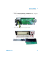
Agilent 34450A
5½ Digit Multimeter
Service Guide
Agilent Technologies
Notices
© Agilent Technologies, Inc., 2012–2013
Warranty
No part of this manual may be reproduced in
any form or by any means (including electronic storage and retrieval or translation
into a foreign language) without prior agreement and written consent from Agilent
Technologies, Inc. as governed by United
States and international copyright laws.
The material contained in this document is
provided “as is,” and is subject to change,
without notice, in future editions. Further,
to the maximum extent permitted by the
applicable law, Agilent disclaims all warranties, either express or implied, with
regard to this manual and any information
contained herein, including but not limited
to the implied warranties of merchantability and fitness for a particular purpose.
Agilent shall not be liable for errors or for
incidental or consequential damages in
connection with the furnishing, use, or
performance of this document or of any
information contained herein. Should Agilent and the user have a separate written
agreement with warranty terms covering
the material in this document that conflict
with these terms, the warranty terms in
the separate agreement shall control.
Manual Part Number
34450-90029
Edition
Third Edition, August 30, 2013
Agilent Technologies, Inc.
5301, Stevens Creek Blvd.
Santa Clara, CA 95051 USA
Technology Licenses
The hardware and or software described in
this document are furnished under a license
and may be used or copied only in accordance with the terms of such license.
Restricted Rights Legend
U.S. Government Restricted Rights. Software and technical data rights granted to
the federal government include only those
rights customarily provided to end user customers. Agilent provides this customary
commercial license in Software and technical data pursuant to FAR 12.211 (Technical
Data) and 12.212 (Computer Software) and,
for the Department of Defense, DFARS
252.227-7015 (Technical Data - Commercial
Items) and DFARS 227.7202-3 (Rights in
Commercial Computer Software or Computer Software Documentation).
II
Safety Notices
CAUTION
A CAUTION notice denotes a hazard. It calls attention to an operating procedure, practice, or the likes
of that, if not correctly performed
or adhered to, could result in damage to the product or loss of important data. Do not proceed beyond a
CAUTION notice until the indicated
conditions are fully understood and
met.
WA R N I N G
A WARNING notice denotes a
hazard. It calls attention to an
operating procedure, practice, or
the likes of that, if not correctly
performed or adhered to, could
result in personal injury or death.
Do not proceed beyond a WARNING notice until the indicated
conditions are fully understood
and met.
34450A Service Guide
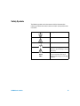
Safety Symbols
The following symbols on the instrument and in the documentation
indicate precautions that must be taken to maintain safe operation of the
instrument.
Earth (ground) terminal
Caution, risk of electric shock
Frame or chassis terminal
Caution, risk of danger (refer to this
manual for specific Warning or Caution
information)
CAT II
300 V
34450A Service Guide
IEC Measurement Category II. Inputs
may be connected to mains (up to
300 VAC) under Category II overvoltage
conditions.
III
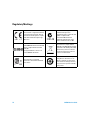
Regulatory Markings
IV
The CE mark is a registered trademark
of the European Community. This CE
mark shows that the product complies
with all the relevant European Legal
Directives.
The C-tick mark is a registered
trademark of the Spectrum
Management Agency of Australia. This
signifies compliance with
the Australia EMC Framework
regulations under the terms of the
Radio Communication Act of 1992.
ICES/NMB-001 indicates that this ISM
device complies with the Canadian
ICES-001.
Cet appareil ISM est confomre a la
norme NMB-001 du Canada.
This instrument complies with the
WEEE Directive (2002/96/EC) marking
requirement. This affixed product label
indicates that you must not discard
this electrical/electronic product in
domestic household waste.
The CSA mark is a registered
trademark of the Canadian Standards
Association.
This symbol indicates the time period
during which no hazardous or toxic
substance elements are expected to
leak or deteriorate during normal use.
Forty years is the expected useful life
of the product.
34450A Service Guide
General Safety Information
The following general safety precautions must be observed during all
phases of operation, service, and repair of this instrument. Failure to
comply with these precautions or with specific warnings elsewhere in this
manual violates safety standards of design, manufacture, and intended
use of the instrument. Agilent Technologies assumes no liability for the
customer’s failure to comply with these requirements.
34450A Service Guide
V
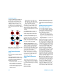
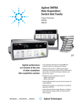
Protection Limits
The Agilent 34450A 5½ Digital Multimeter
provides protection circuitry to prevent
damage to the instrument and to protect
against the danger of electric shock, provided that the Protection Limits are not
exceeded. To ensure safe operation of the
instrument, do not exceed the Protection
Limits shown on the front panel, as defined
below:
E
A
B
C
D
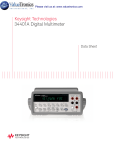
Note: The front-panel terminals and current
protection fuse are shown above.
Input Terminal Protection
Limits
Protection Limits are defined for the input
terminals:
Main Input (HI and LO) Terminals. The HI
and LO input terminals are used for voltage,
resistance, capacitance, and diode test
measurements. Two Protection Limits are
defined for these terminals:
HI to LO Protection Limit. The Protection
Limit from HI to LO ("A" in the figure
above) is 1000 VDC or 750 VAC, which is
also the maximum voltage measurement.
This limit can also be expressed as
1000 Vpk maximum.
VI
LO to Ground Protection Limit. The LO
input terminal can safely "float" a maximum of 500 Vpk relative to ground. This is
Protection Limit "B" in the figure.
Although not shown on the figure, the Protection Limit for the HI terminal is a maximum of 1000 Vpk relative to the ground.
Therefore, the sum of the “float” voltage
and the measured voltage must not exceed
1000 Vpk
Current Input Terminal. The current input
("I") terminal has a Protection Limit of
100 mA (rms) maximum current flowing
from the LO input terminal. This is Protection Limit "C" in the figure. Note that the
current input terminal will be at approximately the same voltage as the LO terminal.
Note: The current-protection circuitry
includes a fuse on the back panel. To maintain protection, replace this fuse only with a
fuse of the specified type and rating.
10 A Current Input Terminal. The 10 A current input terminal has a Protection Limit of
10 A (rms) maximum current flowing from
the LO input terminal. This is Protection
Limit "D" in the figure. Note that the current
input terminal will be at approximately the
same voltage as the LO terminal.
Note: The current-protection circuitry
includes an internal fuse. To maintain protection, service-trained personnel should
replace this fuse only with a fuse of the
specified type and rating.
Sense Terminal Protection
Limits
The HI and LO sense terminals are used
only for four-wire resistance measurements
(" Ω 4W"). The Protection Limit is 200 Vpk
for all of the terminal pairings ("E" in the figure):
LO sense to LO input.
HI sense to LO input.
HI sense to LO sense.
Note: The 200 Vpk limit on the sense terminals is the Protection Limit. Operational
voltages in resistance measurements aremuch lower - less than 5 V in normal operation.
IEC Measurement Category II
Overvoltage Protection
To protect against the danger of electric
shock, the Agilent 34450A 5½ Digital Multimeter provides overvoltage protection for
line-voltage mains connections meeting
both of the following conditions:
The HI and LO input terminals are connected to the mains under Measurement
Category II conditions, defined below, and
The mains are limited to a maximum line
voltage of 300 VAC.
IEC Measurement Category II includes electrical devices connected to mains at an outlet on a branch circuit. Such devices include
most small appliances, test equipment, and
other devices that plug into a branch outlet
or socket. The 34450A may be used to make
measurements with the HI and LO inputs
connected to mains in such devices, or to
the branch outlet itself (up to 300 VAC).
However, the 34450A may not be used with
its HI and LO inputs connected to mains in
permanently installed electrical devices
such as the main circuit-breaker panel,
sub-panel disconnect boxes, or permanently
wired motors. Such devices and circuits are
subject to overvoltages that may exceed the
protection limits of the 34450A.
Note: Voltages above 300 VAC may be measured only in circuits that are isolated from
mains. However, transient overvoltages are
also present on circuits that are isolated
from mains. The 34450A is designed to
safely withstand occasional transient overvoltages up to 2500 Vpk. Do not use this
multimeter to measure circuits where transient overvoltages could exceed this level.
34450A Service Guide
WA R N I N G
• Do not defeat the power cord safety ground feature. Plug in to a grounded
(earthed) outlet.
• Do not use the instrument in any manner that is not specified by the
manufacturer.
• To avoid electric shock or injury, do not operate the multimeter without panels or
case in place.
• Do not substitute parts or modify the instrument to avoid the danger of
introducing additional hazards. Return the instrument to Agilent Technologies
Sales and Service Office for service and repair to ensure the safety features are
maintained.
• Main Power and Test Input Disconnect: Unplug the instrument from the wall
outlet, remove the power cord, and remove all probes from all terminals before
servicing. Only qualified, service-trained personnel should remove the cover from
the instrument.
• Line and Current Protection Fuses: For continued protection against fire, replace
the line fuse and the current-protection fuse only with fuses of the specified type
and rating.
• IEC Measurement Category II. The HI and LO input terminals may be connected to
mains in IEC Category II installations for line voltages up to 300 VAC. To avoid the
danger of electric shock, do not connect the inputs to mains for line voltages
above 300 VAC. See “IEC Measurement Category II Overvoltage Protection” on
the following page for further information.
• Protection limits: To avoid instrument damage and the risk of electric shock, do
not exceed any of the Protection Limits defined in the following section.
• If the Test Lead Set is used in a manner not specified by Agilent Technologies, the
protection provided by the Test Lead Set may be impaired. Also, do not use a
damaged or worn Test Lead Set. Instrument damage or personal injury may
result.
34450A Service Guide
VII
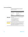
Environmental Conditions
This instrument is designed for indoor use and in an area with low
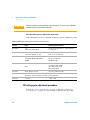
condensation. The table below shows the general environmental
requirements for the instrument.
NOTE
VIII
Requirement
Operating temperature
Full accuracy at 0 °C to 55 °C
Operating humidity
Full accuracy up to 80% RH at 30 °C
(non-condensing)
Storage temperature
–40 °C to 70 °C
Altitude
Operating up to 3,000 meters
Pollution degree
Pollution Degree 2
The Agilent 34450A 5½ Digit Multimeter complies with the following EMC and
safety requirements:
•
•
•
•
•
CAUTION
Environmental Condition
IEC 61010-1:2001 / EN 61010-1:2001 (2nd Edition)
IEC 61326-2-1:2005 / EN61326-2-1:2006
CISPR 11:2003 / EN 55011:2007 Group 1 Class A
Canada: ICES/NMB-001:Issue 4, June 2006
Australia/New Zealand: AS/NZS CISPR 11:2004
Degradation of some product specifications can occur in the presence of ambient
electromagnetic (EM) fields and noise that are coupled to the power line or I/O
cables of the instrument. The instrument will self-recover and operate to all
specifications when the source of ambient EM field and noise are removed or when
the instrument is protected from the ambient EM field or when the instrument
cabling is shielded from the ambient EM noise.
34450A Service Guide
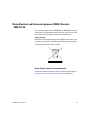
Waste Electrical and Electronic Equipment (WEEE) Directive
2002/96/EC
This instrument complies with the WEEE Directive (2002/96/EC) marking
requirement. This affixed product label indicates that you must not discard
this electrical/electronic product in domestic household waste.
Product Category:
With reference to the equipment types in the WEEE directive Annex 1, this
instrument is classified as a “Monitoring and Control Instrument” product.
The affixed product label is shown as below:
Do not dispose in domestic household waste
To return this unwanted instrument, contact your nearest Agilent office, or
visit www.agilent.com/environment/product for more information.
34450A Service Guide
IX
Additional Notices
The Agilent 34450A is provided with an Agilent 34138A Test Lead Set,
described below.
Test Lead Ratings
Test Leads - 1000 V, 15 A
Fine Tip Probe Attachments - 300 V, 3 A
Mini Grabber Attachment - 300 V, 3 A
SMT Grabber Attachments - 300 V, 3 A
Operation
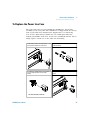
The Fine Tip, Mini Grabber, and SMT Grabber attachments plug onto the
probe end of the Test Leads.
Maintenance
If any portion of the Test Lead Set is worn or damaged, do not use. Replace
with a new Agilent 34138A Test Lead Set.
WA R N I N G
X
If the Test Lead Set is used in a manner not specified by Agilent Technologies, the
protection provided by the Test Lead Set may be impaired. Also, do not use a
damaged or worn Test Lead Set. Instrument damage or personal injury may result.
34450A Service Guide
Declaration of Conformity (DoC)
The Declaration of Conformity (DoC) for this instrument is available on the
Web site. You can search the DoC by its product model or description.
http://regulations.corporate.agilent.com/DoC/search.htm
NOTE
34450A Service Guide
If you are unable to search for the respective DoC, please contact your
local Agilent representative.
XI
THIS PAGE HAS BEEN INTENTIONALLY LEFT BLANK.
XII
34450A Service Guide
Table of Contents
1
Performance Tests and Calibration
Calibration Overview 2
Closed-case calibration 2
Agilent Technologies calibration services
Calibration interval 3
Time required for calibration 3
Automating calibration procedures 3
Recommended Test Equipment
2
4
Test Considerations 5
Input connections 6
Performance Verification Tests Overview
Self test 7
Quick performance check 8
Performance Verification Tests 9
Zero offset verification 9
Gain verification 11
DC current gain verification test 12
Ohms gain verification test 14
Frequency gain verification test 16
AC voltage verification test 17
AC current verification test 19
Capacitance performance verification test
22
Calibration Security 23
Unsecuring the instrument for calibration
24
Calibration Process 26
Using the front panel for adjustments
Adjustments
34450A Service Guide
7
27
29
XIII
Zero adjustment 29
Gain adjustments 29
DC voltage gain adjustment procedure
DC current gain adjustments procedure
AC voltage gain adjustment procedure
AC current gain adjustment procedure
Ohms gain adjustment procedure 36
Capacitance gain adjustment procedure
Frequency gain adjustment procedure
Finishing the adjustments 39
Calibration Message 40
To read the calibration count
Calibration Errors
2
38
39
40
41
Disassembly and Repair
Operating Checklist
44
Types of Services Available
45
Repackaging for Shipment
Cleaning 46
46
To Replace the Power Line Fuse
47
To Replace a Current Input Fuse
48
To Verify your Device License
Self Test Errors
49
50
Electrostatic Discharge (ESD) Precautions
Mechanical Disassembly
Replaceable Parts
Rack Mounting
XIV
30
32
33
35
51
52
58
60
34450A Service Guide
List of Tables
Table 1-1
Table 1-2
Table 1-3
Table 1-4
Table 1-5
Table 1-6
Table 1-7
Table 1-8
Table 1-9
Table 1-10
Table 1-11
Table 1-12
Table 1-13
Table 1-14
Table 1-15
Table 1-16
Table 1-17
Table 2-1
Table 2-2
34450A Service Guide
Recommended test equipment 4
Zero offset verification test 10
DC voltage gain verification test 12
DC current gain verification test 13
Ohms gain verification test 15
Frequency gain verification test 16
AC volts verification test 17
AC current verification test 20
Capacitance verification test 22
Valid gain and frequency compensation input values 30
DC voltage gain adjustment 31
DC current gain adjustment 32
AC voltage gain adjustment 34
AC current gain adjustment 35
Ohms gain adjustment 37
Capacitance gain adjustment 38
Frequency gain adjustment 39
Self test error numbers 50
Replaceable parts list 58
XV
THIS PAGE HAS BEEN INTENTIONALLY LEFT BLANK.
XVI
34450A Service Guide
Agilent 34450A 5½ Digit Multimeter
Service Guide
1
Performance Tests and Calibration
Calibration Overview 2
Recommended Test Equipment 4
Test Considerations 5
Performance Verification Tests Overview 7
Performance Verification Tests 9
Calibration Security 23
Calibration Process 26
Adjustments 29
Calibration Message 40
Calibration Errors 41
This chapter contains performance test procedures and
calibration procedures. The performance test procedures
allow you to verify that the multimeter is operating within
its published specifications.
WA R N I N G
Only service–trained personnel who are aware of the hazards
involved should perform the procedures in this chapter. To avoid
electrical shock and personal injury, make sure you have read and
follow all test equipment safety instructions. Use only completely
electric insulated test lead sets with connectors which are out of
contact with test voltages.
Agilent Technologies
1
1
Performance Tests and Calibration
Calibration Overview
Calibration Overview
NOTE
.
Make sure you have read “Test Considerations” on page 5 before calibrating the
instrument.
Closed-case calibration
The instrument features closed- case electronic calibration. No internal
mechanical adjustments are required. The instrument calculates
correction factors based upon the input reference value you set. The new
correction factors are stored in non- volatile memory until the next
calibration adjustment is performed. Non- volatile EEPROM calibration
memory does not change when power has been off or after a remote
interface reset.
Agilent Technologies calibration services
When your instrument is due for calibration, contact your local Agilent
Service Center for a low- cost re- calibration. The 34450A is supported on
automated calibration systems, which allow Agilent to provide this
service at competitive prices.
2
34450A Service Guide
Performance Tests and Calibration
Calibration Overview
1
Calibration interval
A one year interval is adequate for most applications. Accuracy
specifications are warranted only if adjustment is made at regular
calibration intervals. Accuracy specifications are not warranted beyond
the one year calibration interval. Agilent does not recommend extending
calibration intervals beyond two years for any application.
Time required for calibration
The 34450A can be automatically calibrated under computer control.
With computer control you can perform the complete calibration
procedure and performance verification tests in less than 60 minutes
once the instrument is warmed- up (see“Test Considerations” on page 5).
Refer to the 34450A Programmer’s Reference online help for more
information.
Automating calibration procedures
The adjustment procedures provided in this Service Guide demonstrate
front panel adjustment. You can automate the complete verification and
adjustment procedures outlined in this manual. You can program the
instrument configurations specified for each test over the remote
interface. You can then enter read back verification data into a test
program and compare the results to the appropriate test limit values.
The instrument calibration must be unsecured to perform a calibration.
34450A Service Guide
3
1
Performance Tests and Calibration
Recommended Test Equipment
Recommended Test Equipment
The test equipment recommended for the performance verification and
adjustment procedures is listed in Table 1- 1 below. If the exact
instrument is not available, substitute calibration standards of equivalent
accuracy.
A suggested alternate method would be to use the Agilent 3458A 8½
Digit Digital Multimeter to measure less accurate yet stable sources. The
output value measured from the source can be entered into the
instrument as the target calibration value.
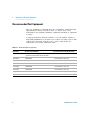
Table 1-1 Recommended test equipment
Application
Recommended Equipment
Recommended Accuracy Requirements
Zero calibration
Fluke 5520A or shorting Plug-Dual banana plug with
copper wire short between the two terminals
DC voltage
Fluke 5520A
<1/5 instrument 1 year spec
DC current
Fluke 5520A
<1/5 instrument 1 year spec
Resistance
Fluke 5520A
<1/5 instrument 1 year spec
AC voltage
Fluke 5520A
<1/5 instrument 1 year spec
AC current
Fluke 5520A
<1/5 instrument 1 year spec
Frequency
Fluke 5520A
<1/5 instrument 1 year spec
Capacitance
Fluke 5520A
<1/5 instrument 1 year spec
4
34450A Service Guide
Performance Tests and Calibration
Test Considerations
1
Test Considerations
Errors may be induced by AC signals present on the input leads during
a self test. Long test leads can also act as an antenna causing pick- up of
AC signals.
For optimum performance, all procedures should comply with the
following recommendations:
• Assure that the calibration ambient temperature is stable and between
18 °C and 28 °C. Ideally the calibration should be performed at
23 °C ±1 °C.
• Assure ambient relative humidity is less than 80 %.
• Allow a two hours warm- up period for performance verification tests
and four hours warm- up period for calibration with a shorting plug
connected to the HI and LO input terminals.
• Use shielded twisted pair PTFE- insulated cables to reduce settling and
noise errors. Keep the input cables as short as possible.
• Connect the input cable shields to earth ground. Except where noted
in the procedures, connect the calibrator LO source to earth ground
at the calibrator. It is important that the LO to earth ground
connection be made at only one place in the circuit to avoid ground
loops.
Because the instrument is capable of making very accurate
measurements, you must take special care to ensure that the calibration
standards and test procedures used do not introduce additional errors.
Ideally, the standards used to verify and adjust the instrument should be
an order of magnitude more accurate than each instrument range fullscale error specification.
For DC voltage, DC current, and resistance gain verification
measurements, you should ensure the calibrator's "0" output is correct.
You will need to set the offset for each range of the measuring function
being verified.
34450A Service Guide
5
1
Performance Tests and Calibration
Test Considerations
Input connections
Test connections to the instrument are best accomplished using the dual
banana plug with copper wire shorted between two terminals for
low- thermal offset measurement. Shielded, twisted- pair, PTFE
interconnect cables of minimum length are recommended between the
calibrator and the multimeter. Cable shields should be earth ground
referenced. This configuration is recommended for optimal noises and
settling time performance during calibration.
6
34450A Service Guide
Performance Tests and Calibration
Performance Verification Tests Overview
1
Performance Verification Tests Overview
Use the performance verification tests to verify the measurement
performance of the instrument. The performance verification tests use
the instrument's specifications listed in the Agilent 34450A User's Guide,
Chapter 4, Specifications.
You can perform four different levels of performance verification tests:
• Self test. A series of internal verification tests that give a high
confidence that the instrument is operational.
• Quick verification. A combination of the internal self tests and
selected verification test.
• Performance verification tests. An extensive set of tests that are
recommended as an acceptance test when you first receive the
instrument or after performing adjustments.
• Optional verification tests. Tests not performed with every
calibration. Perform these tests to verify additional specifications or
functions of the instrument.
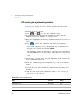
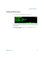
Self test
• This limited test assures that the instrument is capable of operation.
To turn on self test, perform the following steps :
1 Press
>
to enter the Utility menu.
2 Use the navigation keys to move the pointer to SELF TEST and
press
to edit.
3 Press
or
4 Press
to turn on self test.
to select ON.
• If the self test fails, an error is reported on the front panel. You can
also use the SYSTem: ERRor? command query from the remote
interface. If repair is required, contact an Agilent Service Center.
34450A Service Guide
7
1
Performance Tests and Calibration
Performance Verification Tests Overview
• If all tests pass, you have a high confidence (~90%) that the
instrument is operational.
• You can initiate a more complete self test by sending the *TST?
command to the instrument. This command returns a "+0" if all the
self- tests pass, or a "+1" if a failure occurred. This command may
take up to 10 seconds to complete. You may need to set an
appropriate interface time- out value.
Quick performance check
The quick performance check is a combination of internal self test and
an abbreviated performance test (specified by the letter Q in the
performance verification tests). This test provides a simple method to
achieve high confidence in the instrument's ability to functionally operate
and meet specifications. These tests represent the absolute minimum set
of performance checks recommended following any service activity.
Auditing the instrument's performance for the quick check points
(designated by a Q) verifies performance for "normal" accuracy drift
mechanisms. This test does not check for abnormal component failures.
To perform the quick performance check, do the following:
• Perform a self test as described in the preceding section.
• Perform only the performance verification tests indicated in the
following tables with the letter Q.
If the instrument fails the quick performance check, adjustment or repair
is required.
8
34450A Service Guide
Performance Tests and Calibration
Performance Verification Tests
1
Performance Verification Tests
The performance verification tests are recommended as acceptance tests
when you first receive the instrument. The acceptance test results should
be compared against the one year test limits. After acceptance, you
should repeat the performance verification tests at every calibration
interval.
If the instrument fails performance verification, adjustment or repair is
required.
Adjustment is recommended at every calibration interval. If adjustment
is not made, you must establish a 'guard band', using no more than 80%
of the specifications, as the verification limits.
Ensure that you have read the “Test Considerations” on page 5 before running the
performance verification tests.
NOTE
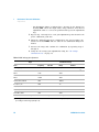
Zero offset verification
This test is used to check the zero offset performance of the instrument.
Verification checks are only performed for those functions and ranges
with unique offset calibration constants. Measurements are checked for
each function and range as described in the procedure on the next page.
34450A Service Guide
9
1
Performance Tests and Calibration
Performance Verification Tests
Zero offset verification test
1 Connect the shorting plug to the HI and LO input terminals. (see
“Input connections” on page 6). Leave the current inputs open.
2 Select each function and range in the order shown in the table below.
Make a measurement and observe the result. Compare measurement
results to the appropriate test limits shown in the Table 1- 2 below:
Table 1-2 Zero offset verification test
Step
Function[1]
Range
Open
DC current
Error from Nominal 1 year
100 µA
±0.015 µA
Open
1 mA
±0.07 µA
Open
10 mA
Open
100 mA
±7 µA
Open
1A
±0.15 mA
Open
10 A
±0.7 mA
Q
±1.5 µA
1 nF
-
Open
10 nF
±0.05 nF
Open
100 nF
±0.5 nF
Open
1 µF
±5 nF
Open
10 µF
±0.05 µF.
Open
100 µF
±0.5 µF
Open
1 mF
±5 µF
Open
10 mF
±0.05 mF
Open
Short
10
Quick Check
Capacitance
DC Volts
±8 µV
100 mV
Q
±50 µV
Short
1V
Short
10 V
±0.5 mV
Short
100 V
±5 mV
Short
1000 V
±50 mV
34450A Service Guide
Performance Tests and Calibration
Performance Verification Tests
1
Table 1-2 Zero offset verification test
Step
Function[1]
Range
Short
Ohms
100 Ω
±8 mΩ[2]
Short
1 kΩ
±80 mΩ[2]
Short
10 kΩ
Short
100 kΩ
±5 Ω
Short
1 MΩ
±50 Ω
Short
10 MΩ
±500 Ω
Short
100 MΩ
±5 kΩ
Quick Check
Q
Error from Nominal 1 year
±500 mΩ[2]
[1] Select 5½ digit (slow mode) measurement resolution
[2] Specifications are for 4-W or 2-W ohms function using the Null math function enabled to
eliminate lead resistance. Without Null, add 0.2 Ω additional error.
Q = Quick performance verification test points
Gain verification
This test checks the full- scale reading accuracy of the instrument.
Verification checks are performed only for functions and ranges with
unique gain calibration constants.
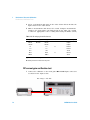
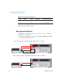
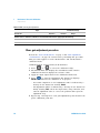
DC voltage gain verification test
1 Connect the calibrator to the front panel HI and LO input terminals
as shown in the figure below :
34450A Service Guide
11
1
Performance Tests and Calibration
Performance Verification Tests
2 Select each function and range in the order shown below. Provide the
input shown in the table below.
3 Make a measurement and observe the result. Compare measurement
results to the appropriate test limits shown in the table. (Be certain
to allow for appropriate source settling when using the Fluke 5520A)
Table 1-3 DC voltage gain verification test
Input
Function[1]
100 mV
DC Volts
Range
Quick Check
Error from Nominal 1 year
100 mV
±26 μV
–100 mV
100 mV
±26 μV
1V
1V
–1 V
1V
10 V
10 V
100 V
100 V
1000 V
1000 V
Q
±0.2 mV
±0.2 mV
±2 mV
Q
±20 mV
±0.2 V
[1] Select Slow Mode 5½ digit measurement resolution
Q= Quick performance verification test points
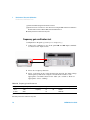
DC current gain verification test
1 Connect the calibrator to the front panel HI and LO input connectors
as shown in the figure below:
For range ≤ 100 mA
12
34450A Service Guide
Performance Tests and Calibration
Performance Verification Tests
1
For range ≥ 1 A , Input < 3A
For range ≥ 1 A , Input ≥ 3A
2 Select each function and range in the order shown below. Provide the
input shown in the table below.
3 Make a measurement and observe the result. Compare measurement
results to the appropriate test limits shown in the table. (Be certain
to allow for appropriate source settling when using the Fluke 5520A.)
Table 1-4 DC current gain verification test
Input
Function[1]
Range
100 μA
DC current
100 μA
±65 nA
1 mA
±0.57 μA
1 mA
10 mA
10 mA
100 mA
100 mA
Quick Check
Q
Error from Nominal 1 year
±6.5 μA
±57 μA
Caution: Connect calibrator to multimeter’s 10 A and LO terminals before applying 1 A and 10 A
34450A Service Guide
13
1
Performance Tests and Calibration
Performance Verification Tests
Table 1-4 DC current gain verification test
Input
Function[1]
Range
Quick Check
Error from Nominal 1 year
1A
1A
Q
±1.15 mA
10 A
10 A
±25.7 mA
[1] Select Slow Mode 5½ digit measurement resolution
Q= Quick performance verification test points
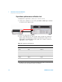
Ohms gain verification test
Configuration: 4- W Ohms (CONFigure:FRESistance) or 2- W Ohms
(CONFigure:RESistance)
1 Connect the calibrator to the front panel HI and LO input terminals
as shown in the figure below:
2- W resistance with compensation (For range 100 Ω ~ 100 kΩ )
2- W resistance without compensation (For range 1 MΩ ~ 100 MΩ )
14
34450A Service Guide
Performance Tests and Calibration
Performance Verification Tests
1
4- W resistance with compensation (For range 100 Ω ~ 100 kΩ )
4- W resistance without compensation (For range 1 MΩ ~ 100 MΩ )
2 Select the 4- W Ohms or 2- W Ohms function.
3 Select each range in the order shown below. Provide the resistance
value indicated. Compare measurement results to the appropriate test
limits shown in the table. (Be certain to allow for appropriate source
settling.)
Table 1-5 Ohms gain verification test
34450A Service Guide
Input
Function[1]
Range
100 Ω
Ohms
100 Ω
Quick Check
Error from Nominal 1 year
±58 mΩ[2]
Q
±580 mΩ[2]
1 kΩ
1 kΩ
10 kΩ
10 kΩ
±5.5 Ω[2]
100 kΩ
100 kΩ
±55 Ω
1 MΩ
1 MΩ
10 MΩ
10 MΩ
100 MΩ
100 MΩ
±650 Ω
Q
±25.5 kΩ
±2.005 MΩ
15
1
Performance Tests and Calibration
Performance Verification Tests
[1] Select Slow Mode 5½ digit measurement resolution
[2] Specifications are for 4-wire for 2- wire ohms function using the Null math function enabled to
eliminate lead resistance. Without Null, add 0.2 Ω additional error.
Q= Quick performance verification test points
Frequency gain verification test
Configuration: Frequency (CONFigure:FREQuency)
1 Connect the calibrator to the front panel HI and LO input terminals
as shown in the figure below:
2 Select the frequency function
3 Select each range in the order shown below. Provide the input voltage
and frequency indicated. Compare measurement results to the
appropriate test limits shown in the table. (Be certain to allow for
appropriate source settling)
Table 1-6 Frequency gain verification test
Voltage
1 Vrms
0.1 Vrms
Input Frequency
1 kHz
20 Hz
Function[1]
Range
Frequency
1V
1V
Quick Check
Q
Error from Nominal 1 year
±0.23 Hz
±0.007 Hz
[1] Select Slow Mode 5½ digit measurement resolution
Q= Quick performance verification test points
16
34450A Service Guide
Performance Tests and Calibration
Performance Verification Tests
1
AC voltage verification test
Configuration: AC Volts (CONFigure[:VOLTage]:AC)
1 Connect the calibrator to the front panel HI and LO input terminals
as shown in the figure below:
2 Select the AC voltage function.
3 Select each range in the order shown below. Provide the indicated
input voltage and frequency. Compare measurement results to the
appropriate test limits shown in the table. (Be certain to allow for
appropriate source settling.)
Table 1-7 AC volts verification test
Error from
Nominal 1 Year
Input Frequency
Function[1]
Range
100 mV
20 Hz
AC voltage
100 mV
±1.1 mV
100 mV
45 Hz
100 mV
±0.3 mV
100 mV
1 kHz
100 mV
±0.3 mV
100 mV
10 kHz
100 mV
±0.3 mV
100 mV
30 kHz
100 mV
±1.8 mV
100 mV
100 kHz
100 mV
±3.3 mV
1V
20 kHz
1V
±11 mV
1V
45 kHz
1V
±3 mV
Vrms
34450A Service Guide
Quick Check
17
1
Performance Tests and Calibration
Performance Verification Tests
Table 1-7 AC volts verification test
Vrms
Input Frequency
Function[1]
Range
Quick Check
Error from
Nominal 1 Year
Q
±3 mV
1V
1 kHz
1V
1V
10 kHz
1V
±3 mV
1V
30 kHz
1V
±18 mV
1V
100 kHz
1V
±33 mV
10 V
20 Hz
10 V
±0.11 V
10 V
45 Hz
10 V
±30 mV
10 V
1 kHz
10 V
±30 mV
10 V
10 kHz
10 V
±30 mV
10 V
30 kHz
10 V
10 V
100 kHz
10 V
±0.33 V
100 V
45 Hz
100 V
±0.3 V
100 V
1 kHz
100 V
±0.3 V
100 V
10 kHz
100 V
100 V
30 kHz
100 V
±1.8 V
100 V
100 kHz
100 V
±3.3 V
750 V
45 Hz
750 V
±2.25 V
750 V
1 kHz
750 V
±2.25 V
750 V
10 kHz
750 V
±2.25 V
Q
Q
±0.18 V
±0.3 V
[1] Select Slow Mode 5½ digit measurement resolution
Q= Quick performance verification test points
18
34450A Service Guide
Performance Tests and Calibration
Performance Verification Tests
1
AC current verification test
Configuration: AC current (CONFigure:CURRent:AC)
1 Connect the calibrator to the front panel HI and LO input terminals
as shown in the figure below:
For range ≤ 100 mA
For range ≥ 1 A , Input < 3A
34450A Service Guide
19
1
Performance Tests and Calibration
Performance Verification Tests
For range ≥ 1 A , Input ≥ 3A
2 Select the AC current function.
3 Select each range in the order shown below. Provide the input current
and frequency indicated. Compare measurement results to the
appropriate test limits shown in the table. (Be certain to allow for
appropriate source settling.)
Table 1-8 AC current verification test
Input
Input Frequency
10 mA
20 Hz
10 mA
Function[1]
AC current
Range
Quick Check
Error from Nominal 1 year
10 mA
±160 µA
45 Hz
10 mA
±60 µA
10 mA
1 kHz
10 mA
10 mA
5 kHz
10 mA
±220 µA
10 mA
10 kHz
10 mA
±220 µA
100 mA
20 Hz
100 mA
±1.6 mA
100 mA
45 Hz
100 mA
±600 µA
100 mA
1 kHz
100 mA
±600 µA
100 mA
5 kHz
100 mA
±2.2 mA
100 mA
10 kHz
100 mA
±2.2 mA
Q
±60 µA
Caution: Connect calibrator to multimeter’s 10 A and LO terminal before applying 1A and 10 A
1A
20 Hz
1A
±16 mA
1A
45 Hz
1A
±6 mA
20
34450A Service Guide
Performance Tests and Calibration
Performance Verification Tests
1
Table 1-8 AC current verification test
Input
Input Frequency
Function[1]
Range
Quick Check
Error from Nominal 1 year
1A
1 kHz
1A
±6 mA
1A
5 kHz
1A
±22 mA
10 A
45 Hz
10 A
±60 mA
10 A
1 kHz
10 A
±60 mA
2A
5 kHz
10 A
±60 mA
[1] Select Slow Mode 5½ digit measurement resolution
Q= Quick performance verification test points
34450A Service Guide
21
1
Performance Tests and Calibration
Performance Verification Tests
Capacitance performance verification test
Configuration: Capacitance (CONFigure:CAPacitance)
1 Connect the calibrator to the front panel HI and LO input terminals
as shown in the figure below:
2 Select the Capacitance function.
3 Select each range in the order shown below. Provide the indicated
input voltage and frequency. Compare measurement results to the
appropriate test limits shown in the table. (Be certain to allow for
appropriate source settling.)
Table 1-9 Capacitance verification test
Range
Function[1]
1 nF
1 nF
Capacitance
10 nF
10 nF
± 0.15 nF
100 nF
100 nF
± 1.5 nF
1 µF
1 µF
± 15 nF
10 µF
10 µF
± 0.15 µF
100 µF
100 µF
± 1.5 µF
1 mF
1 mF
± 15 µF
10 mF
10 mF
± 0.25 mF
Input Capacitance
Error from Nominal 1 year
-
[1] For the best accuracy, take a zero null measurement with open test leads, to null out the test lead
capacitance, before connecting the test leads to the calibrator.
22
34450A Service Guide
Performance Tests and Calibration
Calibration Security
1
Calibration Security
The calibration security code prevents accidental or unauthorized
adjustments to the instrument. When you first receive your instrument, it
is secured. Before you can adjust the instrument, you must unsecure it
by entering the correct security code (see “Unsecuring the instrument for
calibration” on page 24).
The security code is set to AT34450 when the instrument is shipped
from the factory. The security code is stored in non- volatile memory,
and does not change when power is turned off or after a Factory Reset
(*RST command) or after an Instrument Preset (SYSTem:PRESet
command).
NOTE
You can unsecure the instrument from the front panel, but you are not allowed to enter a
new security code or change the security code from the front panel. The security code can
only be changed from the remote interface after the instrument has been unsecured. Refer
to the CAL:SEC:CODE command in the 34450A Programmer's Reference Help File for
more details.
The security code may contain up to 12 alphanumeric characters. The
first character must be a letter. The remaining characters can be letters
or numbers. You do not have to use all 12 characters.
34450A Service Guide
23
1
Performance Tests and Calibration
Calibration Security
Unsecuring the instrument for calibration
Before you can adjust the instrument, you must unsecure it by entering
the correct security code. The security code is set to AT34450 when the
instrument is shipped from the factory. The security code is stored in
non- volatile memory, and does not change when power has been off or
after a Factory Reset (*RST command).
Unsecuring from the front panel
Only five characters (the third through seventh characters) of the
security code are used to unsecure the instrument from the front panel.
If there are letters instead of digits in any of the third through seventh
characters, those letters will be represented as "0" from the front panel.
Example 1
Assume the calibration security code is the factory setting of AT34450.
When unsecuring from the front panel, the code length is five characters
and the first two characters are ignored. In our example, the code now
becomes:
34450
Example 2
Assume the calibration security code was set to AT01A405 from the
remote interface. When unsecuring from the front panel, the first two
characters and any characters after the eighth through twelfth character
are ignored. In our example, the code now becomes:
01A40
From the front panel, any letters (A in this example) are represented by
0. Use this code to unsecure:
01040
24
34450A Service Guide
Performance Tests and Calibration
Calibration Security
1
Example 3
Assume the calibration security code has been set to ATB1 through
remote interface. The first two characters (AT) are ignored. The B is
represented by a zero. The “1” is still used and trailing zeros fill in the
remaining characters. Use this code to unsecure:
01000
To unsecure the instrument from the front panel
1 Press
followed by
to enter the Utility menu.
2 Use the navigator keys to move the pointer to CALIBRATION and
press
to enter Calibration menu.
3 Press
to enter the security code. Use the navigator keys to
step to each character in the code and to select each character.
4 Press
when done.
5 If the correct security code was entered, ACCESS GRANTED is
shown and CAL MODE is shown at the last row.
Unsecure the instrument without the security code.
To unsecure the instrument without a correct security code, send
CAL:SEC:STAT RESET command through the remote interface. The
security code is reset to factory settings (AT34450). Refer to the
CAL:SEC:STAT command in the 34450A Programmer's Reference Help
File for more details.
34450A Service Guide
25
1
Performance Tests and Calibration
Calibration Process
Calibration Process
The following general procedure is the recommended method to complete
a full instrument calibration.
1 Read “Test Considerations” on page 5.
2 Perform the verification tests to characterize the instrument (incoming
data).
3 Unsecure the instrument for calibration (see “Calibration Security” on
page 23).
4 Perform the adjustment procedures (see “Adjustments” on page 29).
5 Secure the instrument against calibration.
6 Note the new security code and calibration count in the instrument's
maintenance records.
NOTE
26
The new security code and calibration count in the instrument’s maintenance records.
34450A Service Guide
Performance Tests and Calibration
Calibration Process
1
Using the front panel for adjustments
This section describes the process used to perform adjustments from the
front panel. Refer to the 34450A Programmer's Reference online help for
remote interface commands.
Selecting the Adjustment Mode
1 Press
>
to enter the Utility menu.
2 Select CALIBRATION and press
to enter Calibration menu.
3 Select CAL MODE and press
to enter Calibration mode. Note
that CAL MODE will not exist in the menu if the instrument is
secured.
Entering adjustment values
In the multimeter adjustment procedures, all calibration point has been
preset. You only need to select the calibration range to start the
calibration process.
Press
or
to select calibration range.
Press
to execute calibration.
Storing the calibration constants
The calibration constants are automatically stored at the end of the
calibration process for each range.
Aborting a calibration in progress
Sometimes it may be necessary to abort a calibration after the procedure
has already been initiated. You can abort a calibration at any time by
pressing
34450A Service Guide
27
1
Performance Tests and Calibration
Calibration Process
CAUTION
28
If you abort a calibration in progress, all calibration constants for the
selected function range are lost. If power is turned off when the
instrument is attempting to write new calibration constants to EEPROM,
all calibration constants for the selected function range may also lost.
Typically, upon re–applying power, the instrument will report Calibration
Corrupt in the Questionable Data Register. Refer to the
STAT:QUES:COND? command in the 34450A Programmer's Reference Help
File for more details. If this occurs, you should not use the instrument
until a complete re–adjustment has been performed.
34450A Service Guide
Performance Tests and Calibration
Adjustments
1
Adjustments
You will need a test input cable and connectors set, and a shorting plug
to adjust the instrument (see “Input connections” on page 6).
NOTE
After each adjustment finishes successfully, the display briefly shows PASS at the status
box. If the calibration fails, the multimeter beeps, the display shows FAIL at the status box.
In the event of a calibration failure, correct the problem and repeat the procedure.
Zero adjustment
Zero adjustments is incorporated in gain adjustments procedure for
selected function.
Gain adjustments
The instrument calculates and stores gain corrections for each input
value. The gain constant is computed from the calibration value entered
for the calibration command and from measurements made automatically
during the adjustment procedure.
Most measuring functions and ranges have gain adjustment procedures.
Adjustments for each function should be performed only in the order
shown.
Gain adjustment considerations
• The zero adjustment procedure must have been recently performed
prior to beginning any gain adjustment procedures.
• Be sure to allow the instrument to warm up and stabilize for four
hours before performing the adjustments.
• Consider the thermal effects as you are connecting test leads to the
calibrator and multimeter. It is recommended to wait one minute
before starting the calibration after connecting the test leads.
34450A Service Guide
29
1
Performance Tests and Calibration
Adjustments
CAUTION
Never turn off the instrument during a gain adjustment. This may cause calibration
memory for the present function to be lost.
Valid gain and frequency compensation input values.
Gain adjustment can be accomplished using the preset calibration points.
Table 1-10 Valid gain and frequency compensation input values
Function
Range
Valid Amplitude Input Values
DC voltage
1V
100 mV, 10 V, 100 V, 1000 V
(0, ±0.2, ± 0.4, ± 0.6, ± 0.8, ± 1, ± 1.2) x Full Scale
± 1 x Full Scale
DC current
100 µA
1 mA, 10 mA, 100 mA, 1 A, 10 A
(0, ±0.2, ± 0.7, ± 1) x Full Scale
(±0.2, ± 0.7, ± 1) x Full Scale
2-W/4-W Resistance
100 Ω,
1 kΩ, 10 kΩ, 100 kΩ, 1MΩ, 10 MΩ
(0, 0.2, 0.7, 1) x Full Scale
(0.2, 0.7, 1) x Full Scale
100 MΩ
100 MΩ and open
100 mV, 1 V, 10 V, 100 V,
(0.1, 0.7, 1) x Full Scale, 1 kHz,
1 x Full Scale, 1 kHz, 10 kHz
(75 V, 200 V, 750 V), 1 kHz,
200 V, 1 kHz, 10 kHz
AC voltage
750 V
AC current
10 mA, 100 mA, 1 A, 10 A
(0.1, 0.7, 1) x Full Scale, 1 kHz
Capacitance
1 nF
10 nF, 100 nF, 1 µF, 10 µF, 100 µF, 1 mF, 10 mF
(0.4, 1) x Full Scale and Open
(0.1, 1) x Full Scale
Frequency
1 V, 1 kHz
1 Vrms, 1 kHz
DC voltage gain adjustment procedure
Review the “Test Considerations” on page 5 and “Gain adjustment
considerations” on page 29 sections before beginning this procedure.
30
34450A Service Guide
Performance Tests and Calibration
Adjustments
1
Calibration mode: DC voltage
1 Apply the input signal shown in the Calibration Point box.
2 Press
to start the adjustment. The Status box displays
CALIBRATING indicates the calibration is in progress.
• Successful completion of each adjustment value is indicated by a
message in the Status box showing PASS.
• An adjustment failure is indicated by a message in the Status box
showing FAIL. Check the input value, range, function, and entered
adjustment value to correct the problem and repeat the adjustment
step.
3 Repeat steps 1 through 2 for each gain adjustment point shown in the
preset Calibration Point box , Table 1- 11 below.
4 When the calibration has been completed for the selected range, the
status box shows DONE, and the value in the Calibration Range box
flashes.
5 Increase the range and continue the calibration by repeating steps 1
through 4.
6 Verify the DC voltage gain adjustments using the “DC voltage gain
verification test” on page 11.
Table 1-11 DC voltage gain adjustment
Input
0 mV[1]
0.2 V, 0.4 V, 0.6 V, 0.8 V, 1 V, 1.2 V, –0.2 V, –0.4 V, –0.6 V, –0.8 V, –1V, –1.2 V
Function
Range
DC voltage
1V
[2]
1V
100 mV, –100 mV
100 mV
10 V, –10 V
10 V
100 V, –100 V
100 V
1000 V, –1000 V
1000 V
Caution: Set the calibrator output to 0 V before disconnecting from the multimeter input terminals.
[1] Cal Item 0 mV only calibrated once during DC voltage gain adjustment procedure. You need to re-calibrate once you exit
calibration mode.
[2] Calibration need to be done on 1 V range first before proceeds to other ranges.
34450A Service Guide
31
1
Performance Tests and Calibration
Adjustments
DC current gain adjustments procedure
Review the “Test Considerations” on page 5 and “Gain adjustment
considerations” on page 29 sections before beginning this procedure.
Calibration mode: DC current
1 Press
or
to select the calibration range.
2 The Measurement box displays the uncalibrated value and the
Calibration Point box displays the reference value.
3 Apply the input signal shown in the Calibration Point box, Table 1- 12
below.
4 Press
to start the adjustment. The Status box displays
CALIBRATING indicates the calibration is in progress.
• Successful completion of each adjustment value is indicated by a
message in the Status box showing PASS.
• An adjustment failure is indicated by a message in the Status box
showing FAIL. Check the input value, range, function, and entered
adjustment value to correct the problem and repeat the adjustment
step.
5 Repeat steps 1 through 4 for each gain adjustment point shown in the
preset Calibration Point box.
6 When the calibration has been completed for the selected range, the
status box shows DONE, and the value in the Calibration Range box
flashes.
7 Increase the range and continue the calibration by repeating steps 1
through 4.
8 Verify the DC current gain adjustments using the “DC current gain
verification test” on page 12.
Table 1-12 DC current gain adjustment
Input
Function
Range
Input terminals open[1]
DC current
Any
20 µA, 70 µA, 100 µA, –20 µA, –70 µA, –100 µA
100 µA
0.2 mA, 0.7 mA, 1 mA, –0.2 mA, –0.7 mA, –1 mA
1 mA
32
34450A Service Guide
Performance Tests and Calibration
Adjustments
1
Table 1-12 DC current gain adjustment
Input
Function
Range
2 mA, 7 mA, 10 mA, –2 mA, –7 mA, –10 mA
10 mA
20 mA, 70 mA, 100 mA, –20 mA, –70 mA, –100 mA
100 mA
Caution: Connect calibrator to multimeter’s 10 A and LO terminals before applying 1 A and 10 A range
0.2 A, 0.7 A, 1 A, –0.2 A, –0.7 A, –1 A
1A
2 A, 7 A, 10 A, –2 A, –7 A, –10 A
10 A
[1] Cal Item OPEN only calibrated once during DC current gain adjustment procedure. You need to re-calibrate once you exit
calibration mode.
Before initiating any gain adjustment procedures, perform the zero adjustment at
any range first.
NOTE
AC voltage gain adjustment procedure
Review the “Test Considerations” on page 5 and “Gain adjustment
considerations” on page 29 on page sections before performing this
procedure.
DC offset calibration and AC voltage flatness calibration has to be done
prior to performing the AC voltage gain adjustments procedure.
Calibration mode: AC voltage
1 Press
or
to select the calibration range.
2 The Calibration Point box displays the first reference value (SHORT).
3 Configure each calibration point as shown in the adjustment
Table 1- 13 on page 34.
4 Press
to start the adjustment. The Status box displays
CALIBRATING indicates the calibration is in progress.
• Successful completion of each adjustment value is indicated by a
message in the Status box showing PASS.
34450A Service Guide
33
1
Performance Tests and Calibration
Adjustments
• An adjustment failure is indicated by a message in the Status box
showing FAIL. Check the input value, range, function, and entered
adjustment value to correct the problem and repeat the adjustment
step.
5 Repeat step 1 through 4 for each gain adjustment point shown in the
preset calibration point box.
6 When the calibration has been completed for the selected range, the
status box shows DONE, and the value in the Calibration Range box
flashes.
7 Increase the range and continue the calibration by repeating steps 1
through 4.
8 Verify the AC voltage gain adjustments using the “AC voltage
verification test” on page 17.
Table 1-13 AC voltage gain adjustment
Input
Vrms
Instrument Settings
Frequency
Shorting plugs between 2 terminals
Function
Range
Cal Item
AC voltage
Any
DC Offset
1 × Full Scale
200 V
1 kHz
1 kHz
100 mV to 100 V
750 V
FLATNESS 1 kHz[1]
1 × Full Scale
200 V
10 kHz
10 kHz
100 mV to 100 V
750 V
FLATNESS 10 kHz
10 mV, 70 mV, 100 mV
1kHz
100 mV
0.1 V, 0.7 V, 1 V
1kHz
1V
1 V, 7 V, 10 V
1kHz
10 V
10 V, 70 V, 100 V
1kHz
100 V
75 V, 200 V, 750 V
1kHz
750 V
Caution: Set the calibrator output to 0 V before disconnecting from the multimeter input terminals.
[1] AC voltage flatness calibration for 1 kHz and 10 kHz need to completed for one range (example 100 mV) first before
proceeding to another range (example 1 V).
34
34450A Service Guide
Performance Tests and Calibration
Adjustments
1
AC current gain adjustment procedure
Review the “Test Considerations” on page 5 and “Gain adjustment
considerations” on page 29 sections before beginning this procedure.
AC voltage gain adjustment for 100 mV range calibration has to be done
prior to performing the AC current gain adjustments procedure.
Calibration Mode: AC current
1 Press
or
to select the calibration range.
2 The Measurement box displays the uncalibrated value and the
Calibration Point box displays the reference value.
3 Apply the input signal shown in the Calibration Point Box.
4 Press
to start the adjustment. The Status box displays
CALIBRATING indicates the calibration is in progress.
• Successful completion of each adjustment value is indicated by a
message in the Status box showing PASS.
• An adjustment failure is indicated by a message in the Status box
showing FAIL. Check the input value, range, function, and entered
adjustment value to correct the problem and repeat the adjustment
step.
5 Repeat step 1 through 4 for each gain adjustment point shown in the
preset calibration point box.
6 When the calibration has been completed for the selected range, the
status box shows DONE, and the value in the Calibration Range box
flashes.
7 Increase the range and continue the calibration by repeating steps 1
through 4.
8 Verify the AC current gain adjustments using the “AC current
verification test” on page 19.
Table 1-14 AC current gain adjustment
Input
Instrument Settings
Current, rms
Frequency
Function
Range
1 mA, 7 mA, 10 mA
1 kHz
AC current
10 mA
10 mA, 70 mA, 100 mA
1 kHz
34450A Service Guide
100 mA
35
1
Performance Tests and Calibration
Adjustments
Table 1-14 AC current gain adjustment
Input
Instrument Settings
Current, rms
Frequency
Function
Range
Caution: Connect calibrator to multimeter’s 10 A and LO terminals before applying 1A and 10 A range.
0.1 A, 0.7 A, 1 A
1 kHz
1A
1 A, 7 A, 10 A
1 kHz
10 A
Ohms gain adjustment procedure
Review the “Test Considerations” on page 5 and “Gain adjustment
considerations” on page 29 sections before performing this procedure.
This procedure applies to both 2- W Resistance and 4- W Resistance
calibration mode.
Calibration Mode: 2- W Resistance/4- W Resistance
1 Press
or
to select the calibration range.
2 The Measurement box displays the uncalibrated value and the
Calibration Point box displays the reference value.
3 Apply the input signal shown in the Calibration Point Box.
4 Press
to start the adjustment. The Status box displays
CALIBRATING indicates the calibration is in progress.
• Successful completion of each adjustment value is indicated by a
message in the Status box showing PASS.
• An adjustment failure is indicated by a message in the Status box
briefly showing FAIL. Check the input value, range, function, and
entered adjustment value to correct the problem and repeat the
adjustment step.
5 Repeat step 1 through 4 for each gain adjustment point shown in the
preset calibration point box.
36
34450A Service Guide
Performance Tests and Calibration
Adjustments
1
6 When the calibration has been completed for the selected range, the
status box shows DONE, and the value in the Calibration Range box
flashes.
7 Verify the Ohms gain adjustments using the “Ohms gain verification
test” on page 14.
Table 1-15 Ohms gain adjustment
Input
Function
Range
0 Ω[1]
2-W Resistance/4-W Resistance
Any
20 Ω, 70 Ω, 100 Ω
100 Ω
0.2 kΩ, 0.7 kΩ, 1 kΩ
1k Ω
2 kΩ, 7 kΩ, 10 kΩ
10 kΩ
20 kΩ, 70 kΩ, 100 kΩ
100 kΩ
0.2 MΩ, 0.7 MΩ, 1 MΩ
1 MΩ
2 MΩ, 7 MΩ, 10M Ω
10 MΩ
100 MΩ
100 MΩ
Input terminal open[2]
2-W Resistance(only)
100 MΩ
Do not remove test lead [3]
2-W Resistance(only)
100 MΩ
[1] Configure to 2-wire compensation mode for calibrator for better accuracy. Cal item 0 Ω only calibrated once during ohms
gain adjustment procedure. You need to re-calibrate once you exit calibration mode.
[2] Remove test lead for 2-wire calibration.
[3] Do not remove kelvin 4-wire connection at the other end of the test leads (for DUT measurement) for 4-W resistance
calibration.
NOTE
Before initiating any gain adjustment procedures, perform the zero adjustment at any range
first.
34450A Service Guide
37
1
Performance Tests and Calibration
Adjustments
Capacitance gain adjustment procedure
Review the “Test Considerations” on page 5 and “Gain adjustment
considerations” on page 29 sections before beginning this procedure.
Calibration Mode: Capacitance
1 Apply the input signal shown in the Calibration Point Box.
2 Press
to start the adjustment. The Status box displays
CALIBRATING indicates the calibration is in progress.
• Successful completion of each adjustment value is indicated by a
message in the Status box showing PASS.
• An adjustment failure is indicated by a message in the Status box
briefly showing FAIL. Check the input value, range, function, and
entered adjustment value to correct the problem and repeat the
adjustment step.
3 Repeat step 1 through 4 for each gain adjustment point shown in the
preset calibration point box.
4 Verify the Capacitance gain adjustments using the “Capacitance
performance verification test” on page 22.
Table 1-16 Capacitance gain adjustment
Input
Function
Range
1 mF, 10 mF
Capacitance
10 mF
0.1 mF, 1 mF
1 mF
10 µF, 100 µF
100 µF
1 µF, 10 µF
10 µF
0.1 µF, 1 µF
1 µF
10 nF, 100 nF
100 nF
1 nF, 10 nF
10 nF
0.4 nF, 1 nF
1 nF
Input terminal open (remove any test leads or shorting plugs
from the input terminals)
Any
38
34450A Service Guide
Performance Tests and Calibration
Adjustments
1
Frequency gain adjustment procedure
Review the “Test Considerations” on page 5 and “Gain adjustment
considerations” on page 29 sections before beginning this procedure.
Calibration Mode: Frequency
1 Apply the input signal shown in the Calibration Point Box.
2 Press
to start the adjustment. The Status box displays
CALIBRATING indicates the calibration is in progress.
• Successful completion of each adjustment value is indicated by a
message in the Status box showing PASS.
• An adjustment failure is indicated by a message in the Status box
briefly showing FAIL. Check the input value, range, function, and
entered adjustment value to correct the problem and repeat the
adjustment step.
3 Verify the Frequency gain adjustments using the “Frequency gain
verification test” on page 16.
Table 1-17 Frequency gain adjustment
Input
Frequency
Function
Range
1 Vrms
1 kHz
Frequency
1 V, 1 kHz
Finishing the adjustments
1 Remove all shorting plugs and connections from the instrument.
2 Reset the Calibration Message (see “Calibration Message”).
3 Record the new Calibration Count (see “To read the calibration
count”).
4 Press
to exit the Calibration Mode.
5 Reset the “Calibration Security” on page 23
34450A Service Guide
39
1
Performance Tests and Calibration
Calibration Message
Calibration Message
The instrument allows you to store a message in calibration memory. For
example, you can store such information as the date when the last
calibration was performed, the date when the next calibration is due, the
instrument's serial number, or even the name and phone number of the
person to contact for a new calibration. The calibration message may
contain up to 40 characters.
You can record a calibration message only when the instrument is
unsecured. You can read the calibration message whether the instrument
is secured or unsecured.
To store a calibration message use the CALibration:STRing command
and to read the calibration message, use the CALibration:STRing?
command from the remote interface.
To read the calibration count
You can query the instrument to determine how many calibrations have
been performed. Note that your instrument was calibrated before it left
the factory. When you receive your instrument, read the count to
determine its initial value.
The count value increments by one for each calibration point, and a
complete calibration will increase the value by many counts. The
calibration count increments up to a maximum of 232- 1 after which it
rolls over to 0. The calibration count can be read either remotely or from
the front panel. To read the calibration count from remote, use the
CALibration:COUNt? command. Use the following procedure to read
the calibration count from the front panel.
1 In the Utility menu/Calibration mode display will show the calibration
count.
40
34450A Service Guide
Performance Tests and Calibration
Calibration Errors
1
Calibration Errors
The following errors indicate failures that may occur during a
calibration.
Error
34450A Service Guide
Meaning
702
Calibration secured
703
Invalid secure code
704
Secure code too long
708
Unable to store calibration data
709
No calibration for this function
720
DCV calibration failed
721
DCI calibration failed
722
RES calibration failed
723
CAP calibration failed
724
FRES calibration failed
725
FREQ calibration failed
726
ACV calibration failed
727
ACI calibration failed
732
ACV flatness calibration failed
41
1
Performance Tests and Calibration
Calibration Errors
THIS PAGE HAS BEEN INTENTIONALLY LEFT BLANK.
42
34450A Service Guide
Agilent 34450A 5½ Digit Multimeter
Service Guide
2
Disassembly and Repair
Operating Checklist 44
Types of Services Available 45
Repackaging for Shipment 46
Cleaning 46
To Replace the Power Line Fuse 47
To Replace a Current Input Fuse 48
To Verify your Device License 49
Self Test Errors 50
Electrostatic Discharge (ESD) Precautions 51
Mechanical Disassembly 52
Replaceable Parts 58
Rack Mounting 60
This chapter will help you troubleshoot a failing multimeter.
It describes how to disassemble the multimeter, how to
obtain repair services, and lists replaceable parts.
Agilent Technologies
43
2
Disassembly and Repair
Operating Checklist
Operating Checklist
Before returning your multimeter to Agilent for service or repair check
the following items:
Is the multimeter inoperative?
q Verify the power line voltage setting.
q Verify the power line fuse is installed.
q Verify that the power cord is connected to the multimeter and to AC
line power.
q Verify the front panel power switch is depressed.
Does the multimeter fail self–test?
q Remove all test connections to the multimeter and run the self–test
again.
Errors may be induced by AC signals present on the multimeter input
terminals during self–test. Long test leads can act as an antenna causing
pick–up of AC signals.
Is the mutimeter’s current input inoperative?
q Verify the current input fuse.
44
34450A Service Guide
Disassembly and Repair
Types of Services Available
2
Types of Services Available
If your instrument fails during the warranty period, Agilent Technologies
will repair or replace it under the terms of your warranty. After your
warranty expires, Agilent offers repair services at competitive prices.
Extended service contracts
Many Agilent products are available with optional service contracts that
extend the covered period after the standard warranty expires. If you
have such a service contract and your instrument fails during the
covered period, Agilent Technologies will repair or replace it in
accordance with the contract.
Obtaining repair service (Worldwide)
To obtain service for your instrument (in–warranty, under service
contract, or post–warranty), contact your nearest Agilent Technologies
Service Center. They will arrange to have your unit repaired or replaced,
and can provide warranty or repair–cost information where applicable.
To obtain warranty, service, or technical support information you can
contact Agilent Technologies at one of the following telephone numbers:
In the United States:
In Europe:
In Japan:
(800) 829–4444
31 20 547 2111
0120–421–345
Or use our Web link for information on contacting Agilent worldwide:
www.agilent.com/find/assist
Or contact your Agilent Technologies representative.
Before shipping your instrument, ask the Agilent Technologies Service
Center to provide shipping instructions, including what components to
ship. Agilent recommends that you retain the original shipping carton for
use in such shipments.
34450A Service Guide
45
2
Disassembly and Repair
Repackaging for Shipment
Repackaging for Shipment
If the unit is to be shipped to Agilent for service or repair, be sure to:
• Attach a tag to the unit identifying the owner and indicating the
required service or repair. Include the model number and full serial
number.
• Place the unit in its original container with appropriate packaging
material for shipping.
• Secure the container with strong tape or metal bands.
• If the original shipping container is not available, place your unit in a
container which will ensure at least 4 inches of compressible
packaging material around all sides for the instrument. Use static- free
packaging materials to avoid additional damage to your unit.
Agilent suggests that you always insure shipments.
Cleaning
Clean the outside of the instrument with a soft, lint- free, slightly
dampened cloth. Do not use detergent. Disassembly is not required or
recommended for cleaning.
46
34450A Service Guide
Disassembly and Repair
To Replace the Power Line Fuse
2
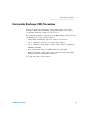
To Replace the Power Line Fuse
The power line fuse is located within the multimeter’s fuse- holder
assembly on the rear panel. The multimeter is shipped from the factory
with a power- line fuse installed. The supplied fuse is a time- delay,
0.25 A 250 V Time- delay 1.9 Ohm 20.5×5.2×5.2mm glass- tube fuse,
Agilent part number 2110- 1533. If you have determined that the fuse is
faulty, replace it with one of the same size and rating.
1 Disconnect power cord. Depress tabs 1 and
2 and pull fuse holder from rear panel.
2 Remove the line voltage selector from fuse
holder assembly.
2
1
3 Rotate line voltage selector and reinstall so
correct voltage appears in fuse holder
window.
4 Replace fuse holder assembly in rear
panel.
100, 120, 220 (230) or 240 Vac
34450A Service Guide
47
2
Disassembly and Repair
To Replace a Current Input Fuse
To Replace a Current Input Fuse
Both the 100 mA and the 10 A current input terminals are fuse
protected. The fuse for the 100 mA input terminal is located on the rear
panel (refer to Agilent 34450A User’s Guide, Chapter 1). The fuse is a
0.4A 500 V fast acting 32×6.3×6.3 mm fuse, Agilent part number 21101503. If you have determined that the fuse is faulty, replace it with one
of the same size and rating.
The fuse for the 10 A current input terminal is located inside the
multimeter and requires partial disassembly of the multimeter. The fuse
is a 11 A fuse, Agilent part number 2110- 1402. If you have determined
that the fuse is faulty, replace it with one of the same size and rating.
48
34450A Service Guide
Disassembly and Repair
To Verify your Device License
2
To Verify your Device License
1 Go to page 2 of the Utility Menu as shown below :
2 If you have purchased the GPIB option, the GPIB Option displays ON.
3 If you have purchased the 50k memory option, the 50k Memory option
displays ON.
4 If you have not purchased any option, the GPIB Option and 50K
Memory display OFF.
34450A Service Guide
49
2
Disassembly and Repair
Self Test Errors
Self Test Errors
The 34450A self test (see the *TST? command) performs a series of
tests on the instrument hardware. Any failure of these tests will generate
a SCPI error number - 330, with additional test failure information. Refer
to the Agilent 34450A Programmer’s Helpfile for more information.
NOTE
On the remote interface, a self–test failure will generate SCPI error –330 and a
supplemental message indicating one of the test numbers shown below. On the front
panel, only the failing test is shown.
The form of this error message is as follows:
- 330,"self test failed; <test# - testname>"
Where test# is the number of the test that failed (range 600 - 607) and
testname describes the test. Here is an example of a test failure message:
- 330,"self test failed; 602 – M/B flash failed"
The following is the list of test numbers and descriptions:
Table 2-1 Self test error numbers
Error Number
Description
600
I/O processor failed self test
601
M/B EEPROM failed
602
M/B flash failed
603
M/B ASIC failed
604
DC low path zero test failed
605
DC high path zero test failed
606
AC path zero test failed
607
GPIB board failed
50
34450A Service Guide
Disassembly and Repair
Electrostatic Discharge (ESD) Precautions
2
Electrostatic Discharge (ESD) Precautions
Almost all electrical components can be damaged by electrostatic
discharge (ESD) during handling. Component damage can occur at
electrostatic discharge voltages as low as 50 V.
The following guidelines will help prevent ESD damage when servicing
the instrument or any electronic device.
• Disassemble instruments only in a static- free work area.
• Use a conductive work area to reduce static charges.
• Use a conductive wrist strap to reduce static charge accumulation.
• Minimize handling.
• Keep replacement parts in original static- free packaging.
• Remove all plastic, foam, vinyl, paper, and other static- generating
materials from the immediate work area.
Use only anti- static solder suckers.
34450A Service Guide
51
2
Disassembly and Repair
Mechanical Disassembly
Mechanical Disassembly
For procedures in this manual, the following tools are required for
disassembly:
• T20 Torx driver (most disassembly)
WA R N I N G
SHOCK HAZARD. Only service–trained personnel who are aware of the hazards
involved should remove the instrument covers. To avoid electrical shock and
personal injury, make sure to disconnect the power cord from the instrument before
removing the covers. Some circuits are active and have power applied even when
the power switch is turned off.
General disassembly
1 Remove power and all cables from the instrument.
2 Remove the carrying handle by rotating the handle upright and pulling
out from the sides of the instrument.
52
34450A Service Guide
Disassembly and Repair
Mechanical Disassembly
2
3 Remove the instrument bumpers. Pull from a corner and stretch the
bumpers off the instrument.
4 Remove the rear bezel. Loosen the two captive screws in the rear
bezel and remove the rear bezel.
34450A Service Guide
53
2
Disassembly and Repair
Mechanical Disassembly
5 Remove the cover. Remove the screw in the bottom of the cover and
slide the cover off the instrument.
Front panel removal
6 Remove the two screws holding the front panel.
54
34450A Service Guide
Disassembly and Repair
Mechanical Disassembly
2
7 Disconnect the ribbon cable connectors from the front panel.
Gre
en
Bla
ck
Bla
ck
wit
hg
rey
con
nec
tor
Whi
te
Red
8 Disconnect the individual front panel wires as shown in the figure
below:
34450A Service Guide
55
2
Disassembly and Repair
Mechanical Disassembly
9 Disconnect the fuse wire as shown in the figure below:
10 There is now enough space to allow the side of the front panel to be
pried from the chassis and removed as an assembly.
56
34450A Service Guide
Disassembly and Repair
Mechanical Disassembly
2
Front panel
1 Remove the keyboard and display assembly. Remove the screw from
the circuit board gently to disengage from the tabs. Lift the keyboard
and display assembly from the plastic housing.
2 Pull the rubber keypad from the plastic housing.
34450A Service Guide
57
2
Disassembly and Repair
Replaceable Parts
Replaceable Parts
This section contains information for ordering replaceable parts for your
34450A. Table 2- 2 on page 58 includes a brief description of each
replaceable part with its corresponding part number.
NOTE
You can find the latest 34450A support parts list at Agilent Test & Measurement Parts
Catalog: http://www.agilent.com/find/parts
To order replaceable parts
You can order replaceable parts from Agilent using the part numbers as
listed in Table 2- 2 on page 58
NOTE
Not all parts listed are available as field-replaceable parts.
To order replaceable parts from Agilent, do the following:
1 Contact your nearest Agilent Sales Office or Service Center.
2 Identify the parts by the Agilent part number shown in the
replaceable parts list.
3 Provide the instrument model number and serial number.
Table 2-2 Replaceable parts list
58
Part Number
Description
34405-30202
Front Panel Assembly
34450-60206
Front Panel
34405-38302
Keypad
34405-43711
Push Rod
34405-40001
Fuse Drawer
A02-62-25604-1
Fuse Carrier
2110-1402
Fuse, Fast acting, 11.0 A, 1000.0 V
34450A Service Guide
Disassembly and Repair
Replaceable Parts
2
Table 2-2 Replaceable parts list
34450A Service Guide
Part Number
Description
2110-1503
Fuse 0.4 A, 500 V Fast Acting 32 × 6.3
2110-1533
Fuse 0.25 A 250 V Time-delay 1.9 Ohm 20.5 × 5.2 × 5.2 mm glass-tube
× 6.3 mm
59
2
Disassembly and Repair
Rack Mounting
Rack Mounting
You can mount the multimeter in a standard 19- inch rack cabinet using
one of three optional kits shown below. Instructions and mounting
hardware are included with each rack- mounting kit. Any Agilent
Technologies instrument of the same size can be rack- mounted beside
the 34450A 5½ Digit Multimeter.
NOTE
You must remove the carrying handle (see page 52) and the front and rear
bumpers (see page 53) before rack mounting the multimeter.
To rack mount a single instrument, order rackmount kit 34190A.
To rack mount two instruments side- by- side, order dual lock- link kit
34194A and dual flange kit 34191A.
60
34450A Service Guide
www.agilent.com
Contact us
To obtain service, warranty, or technical
assistance, contact us at the following
phone or fax numbers:
United States:
(tel) 800 829 4444
(fax) 800 829 4433
Canada:
(tel) 877 894 4414
(fax) 800 746 4866
China:
(tel) 800 810 0189
(fax) 800 820 2816
Europe:
(tel) 31 20 547 2111
Japan:
(tel) (81) 426 56 7832 (fax) (81) 426 56 7840
Korea:
(tel) (080) 769 0800 (fax) (080) 769 0900
Latin America:
(tel) (305) 269 7500
Taiwan:
(tel) 0800 047 866
(fax) 0800 286 331
Other Asia Pacific Countries:
(tel) (65) 6375 8100 (fax) (65) 6755 0042
Or visit Agilent World Wide Web at:
www.agilent.com/find/assist
Product specifications and descriptions in
this document are subject to change
without notice. Always refer to the Agilent
website for the latest revision.
© Agilent Technologies, Inc., 2012–2013
Third Edition, August 30, 2013
34450-90029
Agilent Technologies