1
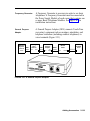
AT&T
518-600-016
MERLIN II
®
COMMUNICATIONS SYSTEM
Installation, Administration,
and Maintenance Manual
©1990 AT&T
All Rights Reserved
Printed in USA
Issue 2
January, 1990
NOTICE
The information in this document is subject to change without notice. AT&T
assumes no responsibility for any-errors that may appear in this document.
MERLIN is a registered trademark of AT&T.
HOLADAY is a trademark of Holaday Industries.
Section 1: System Description
What’s in This Manual
Section 1: System Description
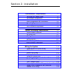
Section 2: Installation
Section 3: Administration
Section 4: Troubleshooting
Section 5: Ordering Information
System Overview
System Configuration
System Features
System Hardware
MERLIN II System Components
Control Unit Components
Module Controls and Indicators
Voice Terminals
Basic Operation of Voice Terminals
System Accessories
Theory of Operation
System Architecture
Analog to Digital Signal Processing
Digital Switching
System Capacity
E&M Signaling
System Connectivity
Simultaneous Voice Data
Local Host Computer Access
Modem Pools
General Requirements for Modems
Music-On-Hold
External Loudspeaker Paging
1-1
1-1
1-1
1-1
1-1
1-1
1-2
1-4
1-7
1-18
1-18
1-18
1-23
1-25
1-29
1-31
1-36
1-36
1-40
1-42
1-44
1-45
1-52
1-52
1-54
1-54
1-58
1-60
1-60
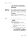
What's in This Manual
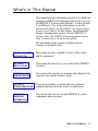
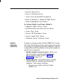
This manual provides information about how to install and
maintain a MERLIN II Communications System. It covers
the MERLIN II System Feature Module 1, Feature Module
2, and Release 3. For further information on specific
features and options, see the MERLIN II Communications
System System Manual for that release. For information
on data communications options with the MERLIN II
system, refer to the MERLIN II Communications System
Data Communications Guide for the release.
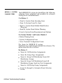
The information in this manual is divided into five
sections, as described below.
SECTION 1: SYSTEM
DESCRIPTION
This section provides a general overview of the system
and its components.
SECTION 2:
INSTALLATION
This section describes how to wire and install a MERLIN
II system.
SECTION 3:
ADMINISTRATION
This section tells you how to customize and administer the
system to meet specific business needs.
SECTION 4:
TROUBLESHOOTING
This section can help you isolate and solve technical
problems that may cause the system to malfunction.
SECTION 5:
ORDERING
INFORMATION
This section tells you how to order MERLIN II system
components and accessories.
What’s in This Manual
1-1
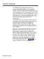
System Overview
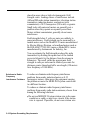
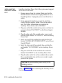
The MERLIN® II Communications System is a
programmable digital telephone system with many
features to make voice and data easy to manage. It
supports up to 56 outside lines and 120 stations, depending
on the configuration. Voice terminals allow access to the
system for conversations, feature programming, or system
administering. By connecting an optional printer to the
system, the user can receive a detailed call report of each
station’s activity and a printout of all system
administration.
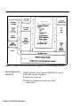
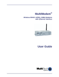
The MERLIN II System is designed to handle integrated
voice and data calls without reducing system capacity. It
can support various terminal types: analog voice
terminals, digital voice terminals, and digital data
terminals. It also supports the new 7102A single-he
voice terminal, Touch-Tone (2500) telephones, and rotary
(500) telephones.
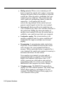
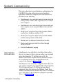
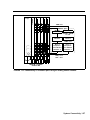
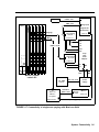
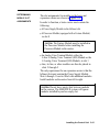
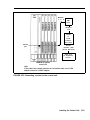
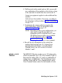
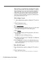
Data and voice options are implemented by selecting the
appropriate station module. There are three types of
station modules: analog modules for analog voice
terminals, basic telephone modules for 7102A, 2500, or
500 sets, and digitaI modules for digital voice terminals
and data devices. Station modules, used with system
accessories, allow the user to select from the simplest
method of voice and data communication to complex
arrangements such as data calls between two digital
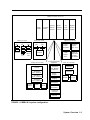
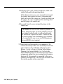
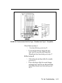
stations and modem pooling. Refer to Figure 1-1 for an
example of MERLIN II system configuration.
1-2 System Overview
MERLIN II System control unit
Power
supply
Modern pool types
Digital
Digital
Digital
port
port
port
MTDM
MTDM
MTDM
Modern
Modern
Modern
2500 Port
BTMI
Central
office
line
Analog
port
Processor
module
Analog
station
module
Basic
telephone
module
MPDM
Host
Computer
Analog voice and data
Display
Console
34-Button
Voice Terminal
22-Button
Voice Terminal
10-Button
Voice Terminal
General
Purpose
Adapter
Modem
Terminal
or PC
Digital
station
module
Digital voice and data
Local host access
Digital Digital
port
port
MPDM
Tie
line
module
Accessories/auxlliary
equipment
Basic
Telephone
and Modem
Interface 2
PT510D
Digital
Voice/Data
7406D/with
display
Digital Voice
7406D
Digital
Voice
7406D/with
Data Stand
Digital
Voice/Data
Basic voice and data
2500 Type
telephone
500 Type
telephone
Music
Coupler
Single/Multizone
Paging
Modem
Terminal
or PC
Alerter
Accessories
MERLIN II
Attendant
Answering
machine
Printer
FIGURE 1-1 MERLIN II system configuration.
System Overview 1-3
SYSTEM
CONFIGURATION
The size, type, and features of a MERLIN II system are
determined using system planning forms.
System Size
A MERLIN II system can be as small as four outside lines
and eight analog voice terminals, or as large as 56 outside
lines and 72 stations. A MERLIN II system with as many
as eight lines and 20 stations is considered a small system
for administration purposes.
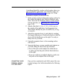
Basic and expanded system capabilities are determined by
these system hardware maximum limitations:
● Thirty-six analog stations with the Simultaneous Voice
and Data feature
● Sixty-four digital stations with the Simultaneous Voice
and Data feature
Eleven line pools
● Seventy-one off-premises devices or Basic Telephone
and Modem Interfaces
●
System Type
1-4 System Overview
A system can be configured for pooled, square, or behindswitch operation. The MERLIN II system default
configuration is pooled with button access.
● In a square system, each outside line has a dedicated
position on a voice terminal. This arrangement is also
known as a key system. In a standard square
configuration, outside lines appear on the same buttons
on each voice terminal. In a customized square
system, different groups of outside lines are assigned
to the same buttons on selected groups of voice
terminals.
In a pooled system, outside lines can be grouped into
line pools (groups of interchangeable lines). To get an
outside line in a pooled system, the user must dial an
access number or use a dedicated pool button on the
voice terminal. Access to outside line pools can also
be had through Automatic Route Selection (ARS).
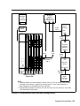
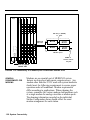
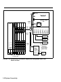
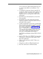
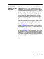
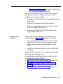
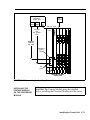
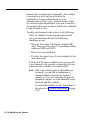
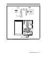
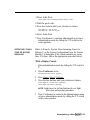
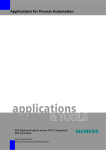
● In a behind-switch system, the MERLIN II system
operates behind a larger system such as a System 25,
75, or 85 PBX. In this configuration, most features of
both systems are available to the MERLIN II system
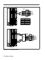
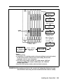
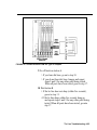
user. Refer to Figure 1-2 for an example of a MERLIN
II system operating behind a digital PBX.
●
System Overview 1-5
Central
office
lines
Network
interface
\
25 Pair cable
Digital PBX
(System 25,
System 75,
or System 85)
DIW cable
66 Type
hardware
/
DIW cable
Jack Field
for outside
lines
Z122C Box
with
Z61OA
Adapters
Power
Supply
D2R
cords
408
408
408
408
408
PFT
PFT
04
08
PFT
PFT
PFT
12
16
03
20
07
11
15
19
02
06
10
14
18
01
05
09
13
17
D8W
cords
08
16
24
32
40
07
15
23
31
39
06
14
22
30
38
05
13
21
29
37
04
12
20
28
36
03
11
19
27
35
02
10
18
26
34
01
09
17
25
33
\
To voice
terminals
and
adjunct
equipment
/
MERLIN II System
contol unit
FIGURE 1-2 A MERLIN II system behind-switch operation.
1-6 System Overview
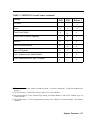
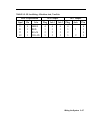
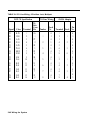
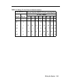
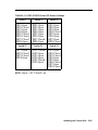
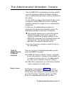
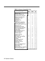
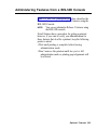
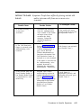
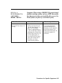
SYSTEM FEATURES
Table 1-1 lists the features that are available for
MERLIN II System Feature Modules 1 and 2, and
Release 3.
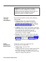
NOTE: The features in Table 1-1 are described fully in
the MERLIN II Communications System System
Manual.
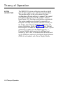
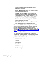
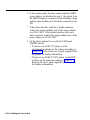
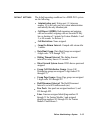
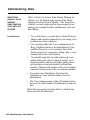
The following paragraphs describe feature that are either
new in Release 3 or have been significantly modified for
Release 3.
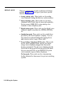
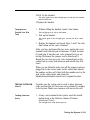
● Disallowed List. Using a Disallowed List, you can
create up to eight lists of numbers, area codes, or
exchanges that selected users will not be permitted to
dial. Each list can have up to 10 numbers. The
administrator may assign one or more of these lists to
any station in the system. If a station is assigned so a
disallowed list any attempt to dial a number contained
in the list wiIl be denied.
● Extended Station Status. Extended Station Status (ES
Status) indicates the operating status of other stations
to the administrator. When ES Status is administered
for Hotel/Motel mode, the attendant can put voice
terminals into different categories to indicate whether
the room is occupied. With Release 3, if the voice
terminal is off-hook, the attendant can’t change its
status. This ES Status Inhibit feature helps prevent
hotel guests from making calls from their room after
they have checked out.
N O T E : The alternative to Hotel/Motel mode is Call
Management System (CMS) mode. CMS is
the automatic call distributor (ACD) for the
MERLIN II system, and is available only with
Feature Module 1 or 2, not Release 3. The
CMS component of the MERLIN II system
answers calls and connects them to available
agents. CMS is not a system feature and
requires a separate software package.
System Overview 1-7
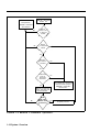
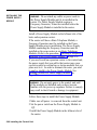
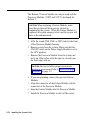
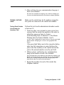
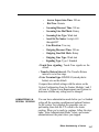
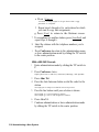
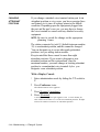
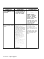
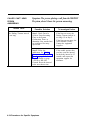
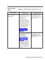
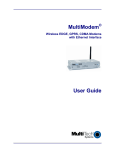
MERLIN II Attendant. The MERLIN II Attendant
automatically answers and routes incoming calls. The
feature is available only when the optional MERLIN II
Attendant accessory is installed. Also, to gain access
to this feature, you must use the517C13 Basic
Telephone (012) Module.
●
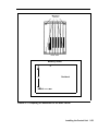
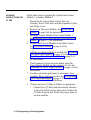
The MERLIN II Attendant performs two major
functions (Figure 1-3):
Immediate call handling, in which all incoming
>
calls are received and routed by the MERLIN II
Attendant. Multiple MERLIN II Attendants can
be used to handle call groups.
Backup call handling, in which incoming calls are
>
directed to the MERLIN II Attendant if the
receptionist (Station 10) does not answer within a
predetermined number of rings.
Each of these functions includes night service call
handling in which the MERLIN II Attendant maybe
used for call coverage only after normal business
hours.
●
●
1-8 System Overview
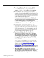
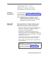
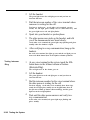
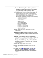
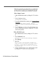
On-Line Module Swap. The On-Line Module Swap
feature allows you to replace a module in the control
unit without powering the system down. The
replacement module must be the same as the one
removed (i.e., a 408 module must be replaced with a
408 module). To use this feature, it is necessary to
follow the exact
procedures described in “On-w
Module Swap, on page 4-7.
Page All. This feature allows you to page all
telephones in the system at once over voice terminal
speakers.
●
●
●
Posted Message. The Posted Message feature
provides a method of sending one of 20 user-defined
messages to another terminal. Each message can be up
to 16 characters long and will appear on the caller’s
display.
System Speed Dial. System Speed Dial allows the
caller to store frequently used numbers as three-digit
codes. For Release 3, the feature has been enhanced to
accommodate 130 speed dial numbers.
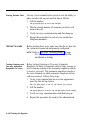
Tie Lines. The MERLIN II system interfaces to a tie
line with E&M signaling through a Tie Line Module.
This feature permits the interconnection of a MERLIN
II system to another MERLIN II system or to other
switches such as a System 25,75, or 85 PBX. (See
“E&M Signaling” on page 1-45 for a description of
E&M signaling.)
System Overview 1-9
MERLIN II Attendant
answers call.
Call transferred to
receptionist;
MERLIN II Attendant
disconnects
▲
No
No
Caller
enters route
or extension
number.
Route
or extension
valid?
Yes
Route
or extension
answers?
Yes
No
Second
route or
extension
answers?
Yes
call transferred; connection
announcement played;
MERLIN II Attendant
disconnects.
No
MERLIN II Attendant
plays Transfer Fail
announcement.
No
Does
caller select
another route
or extension?
Yes
FIGURE 1-3 MERLIN II Attendant o p e r a t i o n .
1-10 System Overview
Repeat process
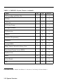
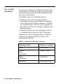
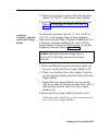
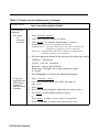
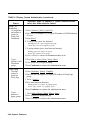
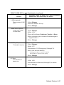
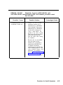
TABLE 1-1 MERLIN II System Features
Feature
FM1
Account Code Entry
x
Allowed List
x
1
FM2
Release 3
x
x
x
x
x
Attendant (Automatic) [MERLIN II Attendant]
Attendant Barge-in
x
x
Attendant Position Setting
x
x
x
Auto Answer All
x
x
x
Auto Answer-Intercom
x
x
x
Auto Intercom
x
x
x
Automatic Line Selection (ALS)
x
x
x
Automatic Route Selection (ARS)
x
x
x
Basic Telephones
x
x
x
x
x
Behind-Switch Operation
Bridging on Shared Lines
x
Call Coverage
x
3
x
3
x
2
x
x
1 The feature name is "Account Number Entry - for Feautre Module 1.
2 The feature name is ‘Executive Barge-In - for Release 3 and can be used from any voice terminal.
3 The feature name is “Bridging” for Feature Module 1 and Feature Module 2
System Overview 1-11
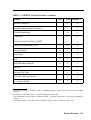
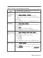
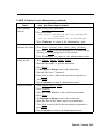
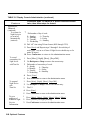
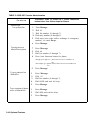
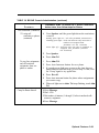
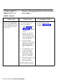
TABLE 1-1 MERLIN II System Features (continued)
Feature
FM1
Call Forwarding and Follow Me
Call Park
x
Call Pickup
x
4
Call Pickup Groups
FM2
Release 3
x
x
x
x
x
4
x
x
x
Call Report (SMDR)
x
x
x
Call Restriction
x
x
x
x
x
Camp On
Centralized Programming
x
x
x
Conference
x
x
x
Coverage Inhibit
x
x
x
Dialing Timeout Internal for Rotary Lines
x
x
x
x
x
Direct Inward System Access (DISA)
4
x
Disallowed List
Display
x
x
x
Do Not Disturb
x
x
x
Drop
x
x
x
4 This feature in Feature Module 2 and Release 3 is the same as "Line Pickup” in Feature Module 1.
1-12 System Overview
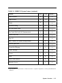
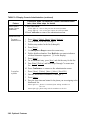
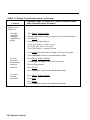
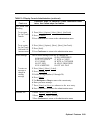
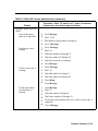
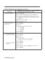
TABLE 1-1 MERLIN II System Features (continued)
Feature
FM1
FM2
5
Release 3
x
Executive Barge-In
x
Extended Station Status (ES Status)
x
x
Flexible Numbering
x
x
Follow Me
x
x
Forced Account Code Entry (FACE)
x
x
Group Call Distribution (GCD)
x
x
x
Group Listening
x
x
x
Group Page
x
x
x
Hold
x
x
x
Hold Disconnect Interval
x
x
x
Intercom
x
x
x
Intercom Dial Tone
x
x
Labels for Lines and Stations
x
Last Number Redial
x
x
8
6
7
x
x
5 For Feature Module 2, the feature name is “Attendant Barge-In” and it operates only from an attendant
station.
6 For Release 3, the feature name is “Call Forwarding and Follow Me”
7 The information for this feature is found in Section 2, "System Components," of the System Manual for
Release 3.
8 For Feature Module 2, the feature name is "labels for Stations” and it is limited to stations only.
System Overview 1-13
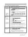
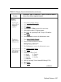
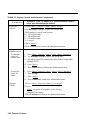
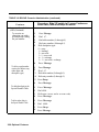
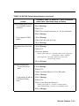
TABLE 1-1 MERLIN II System Features (continued)
Feature
FM1
FM2
Release 3
x
x
x
x
x
9
x
x
x
x
Leave Word Calling
Line Assignments in Behind-Switch Systems
Line Assignments in Pooled Systems
x
Line Assignments in Square Systems
x
1 0
Line Pickup
x
1 1
Line Representation Setting
x
x
Line Request
x
x
x
Loudspeaker Page
x
x
x
Manual Signaling
x
x
x
x
x
Menu Driven Administration
1 2
x
Message
x
x
x
Monitor-on-Hold
x
x
x
1 2
1 3
1 4
9 The feature name is "Line Pools" for Feature Module 1.
10 The feature name is "Square Line Configuration" for Feature Module 1.
11 This feature is called "Call Pickup" for Feature Module 2 and Release 3.
12 The feature name is “System Type” for Feature Module 2 and Release 3.
13 This is not technically a feature of MERLIN II System with Release 3, since menu-driven is the only
administration method for that release. See “Overview” in Section 3, "Reference," of the Release 3 System
Manual for information on menu-driven administration.
14 The information for this feature is found in Section 2, "System Components," of the System Manual for
Release 3.
1-14 System Overview
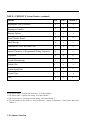
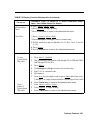
TABLE 1-1 MERLIN II System Features (continued)
Feature
FM1
FM2
Release 3
Music-on-Hold
x
x
x
Night Service
x
x
x
Notify
x
x
x
On-Hook Dialing
x
x
x
On-Line Module Swap
x
One-Touch Hold with Call Announcement
x
x
x
Outside Auto Dial
x
x
x
Page All
x
PBX, Centrex, or Custom Calling Features
x
x
Personal Speed Dial
x
x
x
Personalized Ringing
x
x
x
Posted Message
x
Privacy
x
x
x
Reed
x
x
x
Recall Timer Interval
x
x
x
x
x
Reminder Service
1 5
15 The information for this feature is found in Section 2, "System Components," of the System Manual for
Release 3.
System Overview
1-15
TABLE 1-1 MERLIN II System Features (continued)
Feature
FM1
1 6
FM2
Release 3
x
x
Ringing/Idle Line Preference
x
Ringing-on-Transfer
x
x
x
Ringing Options
x
x
x
Saved Number Redial
x
x
x
Send Message
x
x
x
Simultaneous Voice and Data Calls
x
x
x
Special Characters in Programmed Dialing Sequences
x
x
x
Stopwatch
x
x
x
System Renumbering
x
x
x
x
x
x
x
x
x
System Size
System Speed Dial
System Type
Test
x
1 7
x
x
1 8
x
x
x
19
16 The feature name is “Ringing Line Preference” for Feature Module 1.
17 The feature name is “System Size Setting- for Feature Module 1.
18 This feature name is "Line Represention Setting" for Feature Module 1.
19 The information for this feature is found in Section 2, "System Components," of the System Manual for
Release 3.
1-16 System Overview
TABLE 1-1 MERLIN II System Features (continued)
Feature
FM1
FM2
Tie Lines
Release 3
x
Tones
x
x
x
Touch-Tone Enable
x
x
x
Touch-Tone or Rotary Signaling
x
x
x
Transfer
x
x
x
Transfer Return Interval
x
x
x
Type of Telephone
x
Voice Announcement Enable/Disable
x
Voice Announcement to Busy Telephone
x
2 1
2 2
x
2 2
x
x
x
x
2 3
2 0
2 3
x
20 The information for this feature is found in Section 2, “System Components,” of the System Manual for
Release 3.
21 The feature name is "Touch-Tone or Rotary Setting" for Feature Module 1.
22 The feature name is "Voice Terminal Type Setting" for Feature Module 1, and "Voice Terminal Type" for
Feature Module 2.
23 The feature name is "Voice Announcement to Busy Voice Terminal" for feature Module 1 and Feature
Module 2.
System Overview 1-17
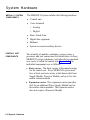
System Hardware
The MERLIN II system includes the following hardware:
MERLIN II SYSTEM
COMPONENTS
●
Control unit
●
Voice terminals
> Analog
> Digital
CONTROL UNIT
COMPONENTS
●
Basic Touch-Tone
●
Digital data equipment
●
Modems
●
System accessories/auxiliary devices
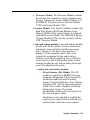
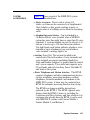
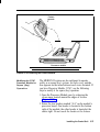
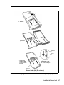
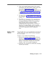
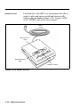
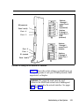
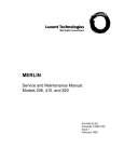
The assembly of modules containing a power source, a
processor, and jack connections for outside lines, tie lines,
MERLIN II system telephones, and other devices mounted
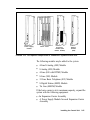
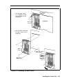
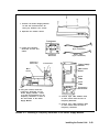
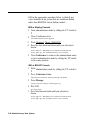
on a carrier is called the control unit (Figure 1-4). The
individual components are as follows:
●
Basic carrier. The basic carrier is the main housing
for the control unit. Every MERLIN II system must
have at least one basic carrier, which houses the Power
Supply Module, Processor Module, and up to five line
and/or station modules.
●
Expansion carrier. The expansion carrier provides
slots for an additional Power Supply Module and six
line and/or station modules. The expansion carrier
does not require a Processor Module.
1-18 System Hardware
Basic carrier
Expansion
carrier
FIGURE 1-4 Control unit components.
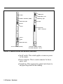
●
Power Supply Module. The Power Supply Module
receives an input of 117 VAC and supplies the system
with the following dc voltages: +5, -5, and -48 VDC.
The Power Supply Module can support up to 45 unit
loads per carrier. (A unit load is a measure of power
used to determine the electrical load of the MERLIN II
system.) if the system’s power requirements exceed 45
unit loads, an Auxiliary Power Unit must be used. This
device supplies an additional 20 unit loads to the
system. For more information on unit loads and the
Auxiliary Power Unit refer to “Determining Unit Load
Requirements” on page 2-57.
If the system uses Basic Telephone (012) Modules, a
Frequency (Ring) Generator must be installed in the
Power Supply Module.
System Hardware 1-19
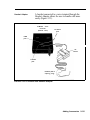
Power supply
module
Line module
with DTMF
(400)
Processor
module (R3)
(with feature
module)
Line
module
(800)
Processor
module
(FM1 and 2)
(with feature
module)
Tie line
module
(400EM)
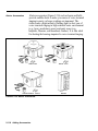
FIGURE 1-4 Control unit components (continued).
1-20 System Hardware
Line/station
module
(408)
Station
module
(000)
Digital
station-module
(008D)
Basic
telephone
module
(012)
●
●
●
Processor Module. The Processor Module contains
the circuitry that controls the system’s programs and
features. It houses the Feature Module. Release 3 of
the MERLIN II System must use Processor Module
517B7 with Feature Module 517F6.
Feature Module. The Feature Module contains the
Read Only Memory (ROM) and Random Access
Memory (RAM) for the system features. It is housed
inside the Processor Module. The MERLIN II Release
3 Feature Module(517F6) must be used only with the
517B7 Processor Module.
Line and station modules. Line and station modules
provide jacks for the system’s tie lines, outside lines,
and stations. Line and station modules can occupy
slots 1 through 5 in the basic carrier and slots 6
through 11 in the expansion carrier. There is no
required slot assignment for line and/or station
modules except that the module in slot 1 of the basic
carrier must be a 408 or 008 module. Either of these
modules provides the user with an analog station port
(port 01) to administer the system.
> Analog line and station modules:
— 4-Line/8-Analog (408) Module. The 408
module is required for a MERLIN II system
minimum configuration. It has four jacks for
outside lines and eight jacks for analog
stations. The 408 module has a Power Failure
Telephone (PFT) jack for connecting a Basic
Touch-Tone or rotary telephone for backup
during power outages. The system
automatically switches service to this jack in
the event of a power failure.
Simultaneous voice and data is available but
requires you to connect both an odd and even
numbered jack to the same voice terminal.
System Hardware 1-21
>
>
>
– 8-Analog (008) Module. The 008 module has
jacks for eight analog stations. It has no jacks
for outside lines. Simultaneous voice and data
is available but requires you to connect both
an odd and even numbered jack to the same
voice terminal.
– 4-Line (400) with DTMF Module. The 400
module has jacks for four outside lines and one
PFT jack. The board has four Touch-Tone
receivers.
– 8-Line (800) Module. The 800 module has
jacks for eight outside lines and two PFT
jacks.
E&M Tie Line (400 EM) Module. A tie line is a
transmission facility dedicated to interconnect two
private switching systems. The MERLIN II system
Tie Line Module may be connected to another
system locally or many miles away. Tie lines are
provided by the telephone company.
Digital (008D) ModuIe. The 8-station digital
module interfaces digital voice and data equipment
to the system. Simultaneous Voice and Data is
available on every port.
Basic Telephone (012) Module. The Basic
Telephone Module permits Touch-Tone or rotary
telephones to be used with the MERLIN II system.
This module provides 12 station jacks and supplies
the tip/ring interface and Touch-Tone circuitry
needed for basic telephones. This module requires
the installation of the Frequency Generator in the
Power Supply Module.
The 517CI 3 Basic Telephone Module must be
installed in order to use the MERLIN II Attendant.
1-22 System Hardware
Label
Power indicator
Auxiliary power
input jack
Diagnostic
96-pin connector
SMDR port
On/Off switch
Application port
Power
connector
Warning light
Ground lug
Power supply module
Processor module (517B7)
for Release 3
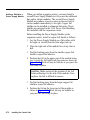
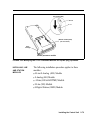
FIGURE 1-5 Module controls and indicators.
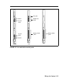
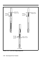
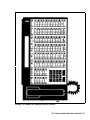
MODULE CONTROLS
AND INDICATORS
The from panel controls, indicators, and special
connectors (excluding line and station jacks) on control
unit modules are described below. Refer to Figure 1-5 to
locate these items.
Power Supply Module. The controls and indicators for
this module are the following:
● Power indicator. Its light goes on when power is
supplied to the module.
● Auxiliary power input jack This jack provides the
interface for the Auxiliary Power Unit.
System Hardware 1-23
SMDR port
Label
Application port
Status indicators (LEDs)
Warning iight
DIP switch (S2)
label
Port 4
Port 3
Diagnostic
96-pin connector
Port 2
Port 1
DIP switch (S1)
Tie line module (517A14)
Processor module (517A7)
for Feature Moduies 1 and 2
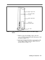
FIGURE 1-5 Module controls and indicators (continued).
On/off switch. This switch applies or removes power
to the earner.
● Power connector. This is a male connector for the ac
power cord.
●
●
1-24 System Hardware
Ground lug. This connects the control unit chassis to
an approved ground for the building.
Processor Module. This module has the following port
and light:
● SMDR port.
This port is an interface to Station
Message Detail Recording (SMDR) for call reports on
call activity or a printout of system administration.
● Warning light. When this red light is lit it indicates
that there is a problem with either the Feature Module,
line or station module, or the Processor Module.
Tie Line Module. The controls and indicators for this
module are the following:
● Status indicators (LEDs). The three status indicators
show the condition of the Tie Line Module.
Green = test condition
Amber = busy
Red = standby mode
Dual In-Line Package (DIP) switch (S2). This switch
controls the signaling format for tie line ports 3 and 4.
● DIP switch (S1). This switch controls the signaling
format for tie line ports 1 and 2.
● Ports 4 through 1.
These ports are jacks for tie lines.
●
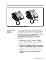
VOICE TERMINALS
Voice terminals are the user’s link to the MERLIN II
system. They are designed to allow easy access to system
features, and have various buttons and indicators to
facilitate operation The buttons on a voice terminal can
function as line buttons or feature buttons. There are fixed
feature buttons for the transfer, hold, recall, conference
and drop features.
Each analog voice terminal has a Test/Program (T/P)
switch that allows testing, programming, and normal
operation. Digital voice terminals are programmed using
a dial code. Other controls on a voice terminal include a
message button, speaker volume control, speaker ON/OFF
button, and red and green lights to indicate status of lines
and features.
System Hardware 1-25
Voice terminals work like special input/output (I/O)
devices. The control unit performs all the decision making
for the system while voice terminals act as the system’s
sensors. Voice terminals inform the control unit of button
depressions and feature status. They also inform the user
of specific conditions by flashing lights or generating
tones.
Voice terminals are connected to the control unit by a
4-pair wire. Each pair has a specific function:
●
Voice 1 pair. The control unit uses this pair of wires
for the primary audio path to and from the voice
terminal. The control unit selects this pair to complete
the path for outgoing, incoming, and intercom calls.
Control pair. The control unit receives information
on voice terminal status and user input on this pair of
wires. It also uses this path to send ringing and lighting
instructions to the voice terminal.
●
Power pair. This pair provides power to the voice
terminal.
●
Voice 2 pair. The control unit uses this pair of wires
for the secondary audio path to and from the voice
terminals. This pair is used with the analog voice
terminal to provide the Voice Announcement to Busy
Voice Terminal and the Simultaneous Voice and Data
features.
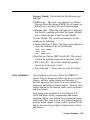
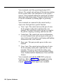
Voice terminals used with the MERLIN II system are
listed here. Refer to Figure 1-6 for examples of analog
voice terminals, including the MERLIN II Display
Console. Figure 1-7 shows digital voice terminals.
●
1-26 System Hardware
●
Analog voice terminals
>
7102A
>
5-Button
>
10-Button
>
10-Button HFAI
10-Button with Built-In Speakerphone (BIS-10)
>
>
BIS-22
BIS-22 with Display
>
34-Button
.>
34-Button Deluxe
>
34-Button (SP-34)
>
34-Button (SP-34D)
>
BIS-34
>
BIS-34 with Display
>
Display Console (used to administer a system with
Release 3)
NOTE:
The new 7102A single-line voice terminal
(not illustrated) has been certified for the
MERLIN II system. It is the same as a basic
telephone and must be connected to a 012
module.
Digital voice terminals
> 7406D
> 7406D with Display
> 7406D with Data Stand
> 7406D with Display and Data Stand
>
●
System Hardware 1-27
10-Button
HFAI
10-Button
BIS-22D
with display
34-button
BIS-34D
with display
BIS-34
Display console
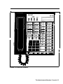
FIGURE 1-6 A selection of analog voice terminals.
1-28 System Hardware
BIS-10
7406D with
Data Stand
7406D with
display and
Data Stand
FIGURE 1-7 A selection of digital voice terminals.
BASIC OPERATION
OF VOICE
TERMINALS
Voice terminals perform a variety of functions. With a
voice terminal, a user can make and receive intercom and
outside calls, page someone, and, with the proper voice
terminal (the attendant console), administer the MERLIN
II system. Buttons on voice terminals maybe
programmed for different functions. The following
paragraph describe the basic operations of voice
terminals.
●
Administration. Two voice terminals, the Display
Console and the BIS-34D, can be used to administer
systems with Feature Module 1 and Feature Module 2.
The Display Console, however, is the only voice
terminal that can administer new MERLIN II Release
3 features. The voice terminal used for administration
must be connected to station jack 01 on the control
unit. During administration, the voice terminal
Test/Program switch must be set to “Program”. This
switch is set to the center position during normal
operation
System Hardware 1-29
●
●
●
●
●
1-30 System Hardware
Dialing out or in. When a voice terminal goes off-
hook, it signals the control unit to make a connection
through a network switch to an available or requested
outside line. When the path is established, the voice
terminal receives a dial tone. The control unit will
select a path in its multiplexing scheme to make the
connection. A call coming into the will
activate the ring indicator in the control unit and
generate control signals to alert the voice terminal.
Intercom call. Intercom calls can be made from one
voice terminal to-any other voice terminal connected to
the control unit. Dialing the intercom number of
another voice terminal will cause the control unit to
establish a voice path between both voice terminals.
Loudspeaker paging. The system interfaces with
auxiliary equipment such as a power amplifier and
loudspeaker for single or multiple zone external
paging.
Programming. In programming mode, instructions
keyed into a voice terminal are stored in the control
unit’s memory; the voice terminal itself has no
memory. When a particular feature is requested by a
voice terminal, the control unit examines its memory to
determine the features for that station.
For an analog voice terminal, you enter and exit
programming mode by using the T/P switch. For a
digital voice terminal, which doesn’t have a T/P
switch, you must use a dial code to enter and exit
programming mode. For a basic voice terminal, the
administrator must program any feature changes.
Telephone paging. The MERLIN II system allows
paging over voice terminal speakers. The Group Page
feature allows paging to a maximum of 10 voice
terminals. The Page All feature allows paging to all
voice terminals in the system.
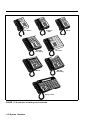
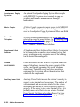
SYSTEM
ACCESSORIES
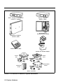
Figure 1-8 shows several of the MERLIN II system
accessories described here.
● Alerter Accessories. Devices such as a horn, bell,
strobe, or chime can be connected to a Supplemental
Alert Adapter so that people working in noisy or
remote areas of a building can be alerted to incoming
calls.
● Attendant Intercom Selector. Can be attached to a
34-Button Deluxe voice terminal when a MERLIN
system has more than eight lines or more than 20 voice
terminals. A system attendant can use the selector’s 30
buttons to access up to 120 Auto Intercom numbers.
The light beside each button indicates whether a voice
terminal or basic telephone is busy and whether a
voice terminal’s message light is on.
● Auxiliary Power Unit. This unit must be added to the
control unit if the total number of voice terminals and
voice terminal accessories (including Hands-Free
Units and Headset Adapters) is greater than the control
unit’s power capacity. The control unit supports up to
45 unit loads, and each Auxiliary Power Unit adds 20
unit loads to the system.
● Basic Telephone and Modem Interface. The BTMI
connects telephones and data communications devices
such as autodialers, answering machines, cordless
telephones, facsimile machines, and modems to the
MERLIN II system. A timer may be connected to a
BTMI for automatic answering based on time of day.
The BTMI is no longer available, having been
replaced by the BTMI-2. The BTMI supports more
features than the BTMI-2, however, including the
Conference and Drop features, and line selection. For
customers who already have the BTMI, it can be used
with MERLIN II systems with Feature Module 1,
Feature Module 2, and Release 3.
System Hardware 1-31
General Purpose
Adapter (GPA)
Basic Telephone and Modem
interface 2 (BTMI-2)
In-Range Out- ofBuilding Protectors (IROB)
Off-Premises Telephone
Interface (OPTI)
Hands-Free Unit (HFU)
Headset with Headset Adapter
Indoor
bell
Indoor
horn
Indoor/outdoor
alerter
Extra alert
strobe
Alerter accessories
FIGURE 1-8 A selection of MERLIN II system accessories.
1-32 System Hardware
●
Basic Telephone and Modem Interface 2 (BTMI-2).
The BTMI-2 is a replacement for the BTMI. It
connects telephones and data communications devices
such as autodialers, answering machines, cordless
telephones, facsimile machines, and modems to the
MERLIN II system. A timer may be connected to a
BTMI-2 for automatic answering based on time of day.
Unlike the BTMI, the BTMI-2 does not support
Conference, Drop, or line selection features. It can be
used with MERLIN II systems with Feature Module 1,
Feature Module 2, and Release 3.
● Basic Telephones. Basic Touch-Tone telephones,
connected to the MERLIN system with the OffPremises Telephone Interface (OPTI) and to outside
telephone lines, provide service to people at a remote
location. On-premises Basic Touch-Tone telephones
can be connected to the system with a Basic Telephone
and Modem Interface 2 or a Basic Telephone Module.
● Frequency Generator. If your basic carrier or
expansion carrier has a Basic Telephone (012)
Module, you must connect a Frequency Generator to
the Power Supply Module, located in the first slot of
each carrier containing Basic Telephone Modules.
The Frequency Generator converts 117-volt, 60-Hz
input power to 105-vol~ 30-Hz ringing voltage for
basic telephones connected to the Basic Telephone
Module.
● General Purpose Adapter (GPA). Permits
connection of accessories such a modem with PCs or
data terminals, cordless telephones, and autodialers to
a MERLIN II system voice terminal. To use this
accessory, you must program Auto Answer AU. The
GPA is for use with all analog voice terminals except
5-button and 10-button HFAI.
System Hardware 1-33
●
●
●
Hands-Free Unit (HFU). Provides the voice terminal
user with full speakerphone capability. This includes
hands-free telephone conversation, on-hook dialing,
monitor-on-hold, and teleconferencing at a short
distance from the voice terminal. To use this
accessory, you must program AUtO Answer- Intercom.
The HFU is for use with all analog voice terminals
except 5-button and 10-button HFAI. An HFU used
with a 7406D voice terminal requires a local power
unit.
Headset-and-Headset- Adapter. Enables a user to
answer and listen to calls without lifting the handset.
The headset and headset adapter is for use with all
analog voice terminals except 5-button and 10-button
HFAI.
In-Range, Out-of-Building (IROB) Analog Voice
Terminal Protectors. A voice terminal can be placed
in another location outside of the main building but
within 1000 feet of the MERLIN H system control
unit. IROB protectors protect the control unit and
voice terminal from exposure to lightning, contact with
power lines, and power currents induced by nearby
power lines.
●
●
1-34 System Hardware
Loudspeaker Paging System. An optional
loudspeaker paging system allows people with
MERLIN II system voice terminals to page co-workers
and/or make announcements through loudspeakers.
Music Coupler. A music coupler connects a music
source (such as a cassette player) to the MERLIN II
system. It also provides a secondary bridged
connection to provide Music-on-Hold. In addition, it
allows the music source to be connected to a
loudspeaker paging system to provide background
music at the same time.
●
Off-Premises Range Extender (OPRE). The OPRE
will be available in place of the Off-Premises
Telephone Interface (OPTI) for users of Feature
Module 1, Feature Module 2, and Release 3. The
OPRE will allow users to connect off-premises
Touch-Tone Basic telephones to the MERLIN II
system.
NOTE: As of this printing the Off-Premises Range
Extender is not available. Installation
information will be supplied in a CIB with the
product.
●
●
●
Off-Premises Telephone Interface (OPTI).
Connects off-premises Touch-Tone Basic telephones
to the MERLIN II system. Allows you to use an offpremises telephone to access many of the features of
the on-premises communication system. The OPTI is
used with MERLIN II Feature Module 1. It can also
be used with Feature Module 2 and Release 3, but only
for two-digit intercom numbers.
Power Failure Telephone. A power failure telephone
allows calls to be made and received in case of a
power failure. A Basic Touch-Tone or rotary
telephone, when connected to a Power Failure
Telephone jack on a module in the control unit, bridges
onto the lowest line number in the block of jacks that it
serves on the module when a power outage occurs.
Supplemental Alert Adapter. Allows Extra Alert
Devices, such as a horn, bell, strobe, or chime, to be
connected to an analog voice terminal jack so that
people working in noisy or remote areas of a building
can be alerted to incoming calls.
System Hardware 1-35
Theory of Operation
SYSTEM
ARCHITECTURE
The MERLIN II system architecture provides a digital
network that supports voice and data communications.
The modular nature of the system makes the base
configuration efficient and easy to expand. The control
unit contains the memory for the system’s features,
Input/Output (I/O) functions, and interface requirements.
The various modules are electrically connected to a
backplane assembly that provides common circuitry for
the I/O bus, Time Division Multiplex (TDM) bus, and
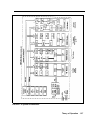
power distribution. Refer to Figure 1-9 for a fictional
block diagram of MERLIN II system architecture. System
architecture is made up of the following items: a
Processor Module interconnected to intelligent port
modules by an I/O bus; a communications network made
up of a TDM bus connected to the DigitaI Switch Element
(DSE) of each module; and a Power Supply Module.
1-36 Theory of Operation
FIGURE 1-9 System architecture.
Theory of Operation
1-37
●
●
●
●
●
1-38 Theory of Operation
Power Supply Module. The Power Supply Module
converts 117 VAC line voltage to the following
outputs: +5 VDC, -5 VDC, and -48 VDC (tip/ring).
Processor Module. The central processor complex
consists of a main board and the Feature Module. The
main board contains the 68000 microprocessor, RAM,
a real-time clock, interrupt circuitry, and port interface
to the modules through the I/O bus.
Communication between the Processor Module and
the port processors on the various modules occurs over
a parallel address/data bus. This structure allows
memory-mapped I/O with up to 1 megabyte per second
bandwidth.
Input/Output Bus. Included in the I/O bus are a 16bit address bus and an 8-bit data bus. The address bus
selects the module that receives instructions from the
68000 microprocessor. The microprocessor provides
instructions to the port processors and Digital Switch
Elements (DSEs) through the 8-bit data bus.
Time Division Multiplex Bus. The Time Division
Multiplex bus (TDM) is a major part of the control
unit. It connects the DSEs to allow voice and data to
flow in and out of the MERLIN II system. The TDM
bus is parallel, 8 bits wide, and runs at 2.048 MHz.
Each TDM cycle has 256 time slots for voice, data,
tones, and clocks.
Voice signals on the TDM bus are encoded in “MuLaw 255” Pulse Code Modulation (PCM) format for
domestic use and “A-Law 100” for international
applications. See “Analog to Digital Signal
Processing” on page 1-40. Data signals are processed
according to Digital Communications Protocol (DCP).
408 or 008 Module. A 408 Loop Start Line/ATL
Station Module or 008 module is required in slot 1 of
the basic carrier of the control unit. Note, however,
that the 008 module does not provide any outside lines
●
●
If you use a 008 module in this slot, you must provide
for outside lines using another module.
The 408 module has a port processor to handle realtime intensive tasks such as ATL line protocol and
central office rotary outpulsing. The port processor
receives instructions from the main processor over the
I/O bus. The instructions are stored in the dual port
RAM. Buffer circuitry interfaces the I/O bus to the
port processor.
The 408 module converts analog signals to digitaI for
switching. Analog signals come into the 408 module
through the outside lines and are converted to digital
levels by coder-decodes (codecs). Voice and data
signals going to the station jacks are converted to
analog signals by codecs. Interface circuitry couples
the analog output to the station jack. The DSE
interfaces voice and data with the TDM bus. The main
processor (through the 1/0 bus) directs the DSE to
place or remove samples from the TDM bus in specific
time slots.
008D Module. The 008D Digital Module provides a
digital interface to the system for PCs and other data
devices. This module does not require codecs because
no analog to digital conversion is required. Data flow
through the module is controlled by the port processor,
which receives its instructions from the I/O bus. Dual
Line Interface (DLI) circuitry assures proper clocking
and synchronization during all transfer cycles.
012 Module. The 012 Module interfaces basic
telephones to the MERLIN II system. It provides the
-48 VDC tip/ring voltage and monitors the circuit for
tip/ring conditions. The 012 module converts analog
signals into digital levels for interface to the TDM bus
and provides -24 VDC for the Ring relay. When a
basic telephone goes off-hook and dials a number, ring
control circuitry closes the ring voltage relay. At this
point, ring control circuitry outputs signals to the port
Theory of Operation 1-39
processor. The port processor directs Touch-Tone
circuitry to output tones. The tones are placed on the
TDM bus by the DSE through buffer circuitry. After a
tip condition occurs at the remote end, a conversation
may occur.
ANALOG TO DIGITAL
SIGNAL
PROCESSING
The MERLIN II system receives analog signals from the
central office lines and analog modules. In order to be
switched, the analog signals must be converted to digital
signals. Digital transmissions have several advantages
over analog transmissions. They produce superior bit
error rates and have lower noise/signal degradation,
simpler circuitry in some cases, and greater flexibility.
They also have various performance advantages, such as
speed and a nonblocking architecture.
If an analog signal is sampled in increments equivalent to
twice the frequency of that signal, then the sample can
faithfully reproduce the signal at a digital level.
Analog to Digital
Signal Conversion
The first step in analog to digital conversion is to sample
the pulse amplitude of the analog signal. Then the sample
is converted into a series of amplitude steps. This
technique is referred to as Pulse Amplitude Modulation
(PAM). Analog to digital converters (codecs) are an
integral part of voice and data systems. Codecs use a
variety of encoding techniques. The MERLIN II system
uses Pulse Code Modulation (PCM).
The process of converting an analog signal to a digital
level increases the capacity and efficiency of data
transmissions. However, a digitized analog signal retains
some of the problems of older transmission systems, such
as having to be amplified.
1-40 Theory of Operation
PCM uses PAM as its starting point but goes further.
PCM digitizes the information and sends the 8-bit code via
PAM. PCM digitizes the PAM information by comparing
each PAM sample to a point on a chart. Each point has a
distinct 8-digit binary code. Therefore, it is the binary
code, not the amplitude pulse, that is transmitted in PCM.
Quantizing
The process of converting PAM samples into discrete
PCM values is known as “quantizing”. In the case of voice
grade signals eight bits are commonly used to encode one
PAM sample. Quantizing with eight bits allows 256
unique values to represent the analog signal being
sampled. With adequate sampling of an analog voice
signal, the digital product can be toll quality.
The quantizing process creates errors due in part to the
“rounding off” of PAM samples into discrete PCM values.
This distortion can be minimized by increasing the number
of bits used to sample the analog signal or to increase the
sampling rate.
Commanding
Distortion also occurs in the quantizing process because
equal consideration is given to all amplitude levels. Linear
quantizing divides the amplitude range into equal
segments which results in unnecessary quality at levels
where voice signals are unlikely to occur. Commanding
eliminates this distortion by using a nonlinear scale which
has smaller divisions and more accuracy in areas of the
scale where voice signals are most likely to occur.
Commanding is, in effect, a compression/expansion of the
quantizing scale. This nonlinear scale is more accurate in
areas where signal amplitudes occur most (thereby
reducing quantizing distortion). The scale is less accurate
in areas where signal amplitudes occur least (resulting in
more quantizing distortion).
Theory of Operation 1-41
Mu-Law 255
Mu-Law 255 is a commanding scheme which uses a
compression ratio that is compatible with modern channel
bank equipment. The scale is divided into 16 intervals,
with each interval having 16 levels. Therefore, it has 256
discrete values. Mu-Law 255 has a negative and positive
zero; therefore, it really has 255 discrete values. This
commanding scheme is used in the United States and
Japan.
A-Law 100
The commanding scheme used in Europe is A-Law. It
follows the same basic theory as Mu-Law 255 except that
its scale is different. The scale tends to be more linear than
Mu-Law 255. Because the intends tend to be equal, ALaw 100 does not concentrate its accuracy in areas of the
scale where voice signals occur the most.
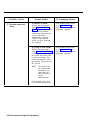
DIGITAL SWITCHING
The Time Division Multiplex (TDM) bus allows many
users to communicate over a common electrical
connection. The TDM bus is physically distributed across
the backplane of the control unit and connects all
line/station modules. It is 8 bits wide and has a frequency
of 2.048 MHz. The frame repetition rate is 8 KHz
providing a 64 Kbps channel on each of the 256 time slots.
The TDM bus has specific time slots for various functions.
During a conversation between station A and station B, a
time slot is reserved for station A to transmit on and
another for station B to receive on. Because the TDM bus
cycles 8 thousand times per second, the conversation is
continuous. The TDM bus carries tones and control
signals to stations. Unlike other bus configurations, the
stations on the TDM bus receive all transmissions. If a
station is not assigned to any of the time slots, the TDM
bus will ignore the data. Refer to Figure 1-10 for an
example of the TDM bus.
The Digital Switch Element (DSE) functions as a digital
switch for voice and data. It also performs the operations
for commanding schemes such as A-Law and Mu-Law.
1-42 Theory of Operation
Each module has a DSE to interface codecs or digital
transceivers to the TDM bus. The actual digital switching
occurs when the DSE is programmed by the system I/O
bus to place (transmit) data or retrieve (receive) data on
the TDM bus in specific time slots. This process also
involves time slot interchanging so that an available slot in
the TDM cycle can be filled with a talk (transmit) or listen
(receive) slot. The DSE provides dynamic conferencing
ability by allowing up to 16 time slots to be conference
together and sent out to a single port (station).
408 Module
CODEC
DSE
D/A
converter
A/D
converter
i
n
t
e
r
f
a
c
e
008D Module
Analog
voice
terminal
DSE
Interface
circuity
TDM Bus
256 Time slots in one TDM cycle
0 1 2 3
Time slots
for control
signals.
…
60 61 62 63
…
Time slots
for tones.
150
… 160
…
Analog station
talks on time
slot 150 and
listens on time
slot 160. The
conversation
is continuous.
200
… 220 … 225
Time
Digital station
sends data on
time slot 200
and receives
data on time
slot 220.
FIGURE 1-10 Time division multiplexing.
Theory of Operation 1-43
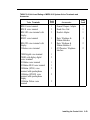
SYSTEM CAPACITY
The MERLIN II system hardware limits the system
capacity for the items found in Table 1-2.
TABLE 1-2 MERLIN II System Capacity
Item
Capacity
Module slots
17
Board signatures
16
Time slots
-
256
Simultaneous duplex connections
Tones
108
40
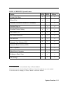
Table 1-3 lists items that the system architecture either
allows or requires.
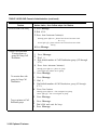
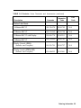
TABLE 1-3 Port Requirements for Features and System
Accessories
Feature
1-44 Theory of Operation
Port Requirements
Music-on-Hold interface
1 CO line (administered)
External paging interface
1 CO line (administered)
Analog Simultaneous Voice/Data
2 ATL station ports
Analog Voice Announcement
to Busy Voice Terminal
2 ATL station ports
Digital Simultaneous Voice/Data
1 DCP station port
Extra alert devices (with SAA)
1 ATL station port
E&M SIGNALING
Most signaling systems, other than loop signaling, are
separate from the trunk equipment. They are normally
located between the trunk equipment and the line facility.
E&M signaling systems derive their name from the
historical designations of the signaling leads on
schematics covering these systems. By convention, the
"E" stands for ear and the "M" stands for mouth (rEceive
and transMit). The E&M lead signaling interface consists
of two leads between the switching equipment (central
office) and the signaling equipment (PBX). The “M lead
carries signals from the switching equipment to the
signaling equipment. The “E” lead carries return signals
from the signaling equipment to the switching equipment.
The E&M interface is designated as TL31M, and the 50pin connector is designated as RJ2GX. At the RJ2GX
interface, the PBX is the switching equipment side, and
the network side (toward the central office) is the
signaling equipment side. An example of E&M signaling
is shown in Figure 1-11.
Theory of Operation 1-45
MERLIN II
System
T
R
T1
R1
M
E
RJ2GX
Central
office
Central
office
RJ2GX
T1
R1
T
R
E
M
Dimension
PBX
SITE #2
SITE #l
Off-hook
Dial tone
Site #1 dials
number for
site #2
M lead
M lead of site #1 connected to
E lead of site #2
E lead
Ring
Off-hook
E lead
M lead of site #2 connected to
E lead of site #1
M lead
Conversation
On-hook
On-hook
E lead
Disconnect
M lead
M lead
Disconnect
E lead
FIGURE 1-11 E&M signaling.
E&M Tie Line
Parameters
The MERLIN II system 400EM Tie Line Module has four
line ports. Each must be administered individually. All tie
line options are software administered except for the
signaling format parameters (signaling mode and signaling
type). These are selected by DIP switches on the Tie Line
Module. The following is an explanation of tie line
options. For more information, see “Administering Tie
Lines” on page 3-50 in Section 3, “Administration”.
1-46 Theory of Operation
Direction A tie line may be administered in one of the
three following ways:
●
Two-way (default): Calls may be made in either
direction.
●
Outgoing only: Calls may be made but not received.
●
Incoming only: Calls may be received but not made.
Type There are four types of tie line options.
●
●
●
●
Wink start (default): The originating end of the tie line
transmits an off-hook signal and waits for the remote
end to send a signal indicating that it is ready (a wink).
This is also know as a dial repeating tie line.
Automatic start: Incoming calls are routed directly to
an attendant station without a start signal. This is also
known as an automatic ringdown tie line.
Immediate start: No start dial signal is necessary.
Dialing may begin immediately following seizure of a
line. This is also known as a dial repeating tie line.
Delay dial start: The originating end of the tie line
transmits an off-hook signal and waits for the remote
end to send a delay dial signal (an off- hook signal
followed by an on-hook signal). This is also known as
a dial repeating tie line.
Signaling Mode Signaling mode designates the
electrical interface used.
●
E&M mode: The signaling leads are isolated from the
transmission leads. The E&M mode can be either
protected or unprotected.
The protected mode must be used
whenever the E&M leads extend out-of-building
and are not connected to the network interface.
WARNING:
Theory of Operation
1-47
Unprotected mode: Must be used for the E&M
Type 1 Standard interface in order to meet voltage
drop criteria for the interface. This mode is used
when there is a network interface.
● Protected mode: Resistance is added in tie M lead
to provide additional protection from foreign
voltages and transients. This mode is used on local
tie lines, such as between systems in different
buildings.
Simplex mode: The signaling leads are superimposed
onto the analog transmission leads to provide a twopair interface. Resistance is included in the signaling
leads for protection from foreign voltages and
transients. This mode is used primarily with E&M
Type 5 signaling on local tie lines.
●
●
Signaling Type Signaling type designates the logical
signaling used. There are the following three options:
●
Type 1 Standard (default): The M leads are used for
signaling from PBX to line. Off-hook is -48 VDC and
on-hook is local ground. Signaling in the other
direction uses local ground for off-hook and open for
on-hook.
● Type 1 Compatible: This interface is back-to-back
compatible with Type 1 Standard. It allows direct
connection between systems where no intermediate
signaling equipment is used.
● Type 5: A symmetrical 2-wire arrangement that signals
in both directions by means of open for on-hook and
ground for off-hook. The primary application of Type5 interface is local tie lincs.
1-48 Theory of Operation
Dialing Mode This option sets the dialing mode for the
tie line.
Touch-Tone
● Rotary (default)
●
Dial Tone This option determines whether the dial tone
originates from the remote or local end of the tie line, or
both (you receive a second dial tone).
●
●
Remote (default)
Local
Answer Supervision Time This option sets a time limit
in milliseconds (ms) for the remote station to signal the
calling station.
● 20 to 4800 ms (increments of 20 ms)
● 300 ms (default)
Tie Line Disconnect Time This option sets a time limit
for the release of the E or M lead.
● 140 to 2400 ms (increments of 10 ms)
●
300 ms (default)
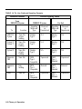
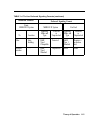
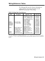
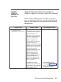
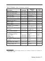
Your choice of signaling format (signaling mode and type)
depends on the particular application. Using Table 1-4
“Tie Line Preferred Signaling Formats,” you can
determine tie line compatibility between the MERLIN II
System and other systems.
Theory of Operation 1-49
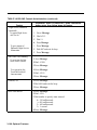
TABLE 1-4 Tie Line Preferred Signaling Formats
Preferred Signaling Format
Installation Situation
From
MERLIN II System
To
Location
MERLIN II System
Far End
Signaling
Mode and
Type
Protected
or
Unprotected
Signaling
Mode and
Type
Protected
or
Unprotected
MERLIN II
System
Same Site
or Interbuilding
Simplex
Type 5
N/A
Simplex
Type 5
N/A
System 25
System 75
Same Site
or Interbuilding
Simplex
Type 5
N/A
Simplex
Type 5
N/A
System 85
Same Site
or Interbuilding
Simplex
Type 5
N/A
Simplex
Type 5
N/A
Dimension
PBX
Same Site
E&M
Type 1
Compatible
Unprotected
E&M
Type 1
Standard
Unprotected
Dimension
PBX
Interbuilding
E&M
Type 1
Compatible
Protected
E&M
Type 1
standard
Protected
Other
Same Site
E&M
Type 1
Compatible
Unprotected
E&M
Type 1
Standard
Unprotected
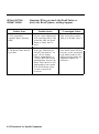
1-50 Theory of Operation
TABLE 1-4 Tie Line Preferred Signaling Formats (continued)
Insulation Situation
From
MERLIN II System
To
Location
Preferred Signaling Format
Far End
MERLIN II System
Signaling
Mode and
Type
Protected
or
Unprotected
Signaling
Mode and
Type
Protected
or
Unprotected
Other
Interbuilding
E&M
Type 1
Compatible
Protected
E&M
Type 1
Standard
Requires a
protection
unit
Network
interface
…
E&M
Type 1
Standard
Unprotected
Either
Either
Theory of Operation 1-51
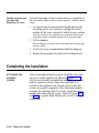
System Connectivity
This section describes typical hardware configurations for
a MERLIN II system with accessories and auxiliary
equipment Connectivity diagrams with descriptions are
provided for the following:
●
●
Simultaneous voice and data (digital station) and local
host computer access using the digital station module
(008D).
●
Modem pool using the digital station module (008D)
and the basic telephone module (012).
●
Modem pool using the digital station module (008D)
and the analog station module (408).
●
Modem pool on dedocated outside lines for data-
●
Background music provided for callers through
Music-on-Hold.
●
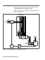
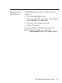
SIMULTANEOUS
VOICE AND DATA
Simultaneous voice and data (analog station) using the
analog station module (408) to gain access to a remote
host computer.
External loudspeaker paging.
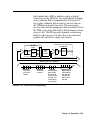
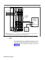
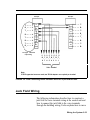
Simultaneous voice and data at an analog station allows
the user to connect to the system an analog voice terminal
and a data terminal or PC with data rates set by the
modem. This feature requires both an odd and even jack
to be connected to the voice terminal. Refer to the
connectivity diagram in Figure 1-12.
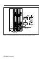
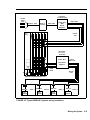
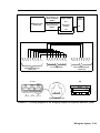
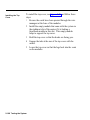
Simultaneous voice and data at a digital station allows the
user to have a digital voice terminal and a data terminal or
PC with data rates up to 19,200 bps between digital
endpoints. Note that between the Modular Trunk Data
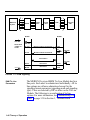
Module (MTDM) and the modem there can be a maximum
of 17 feet. Refer to the connectivity diagram, especially
Note 2, in Figure 1-13.
1-52 System Connectivity
Bridging
adapter
BR 241-B1
Even Station Odd
Remote
host
computer
■
Modem
■
■
D8W
cord
Central
Office
Power
Supply
Analog
voice
terminal
■
Line
Other
■
408 408 408 408 408
PFT
04
03
02
01
PFT
08
07
06
05
PFT
12
11
10
09
PFT
16
15
14
13
D8AC
cord
PFT
20
19
18
17
■
VT
General
Purpose
Adapter
Tel Equip
cord
08
07
06
05
04
03
02
01
16
15
14
13
12
11
10
09
24
23
22
21
20
19
18
17
32
31
30
29
28
27
26
25
40
39
38
37
36
35
34
33
D8W
cord
■
D4BU
cord
■
See Notes 1
and 2
Line
Modem
2212C
Terminal
■
RS-232-C
(M25B)
MERLIN II System
Control unit
Data
terminal
or PC
Notes:
1. Bridging adapter connects adjacent odd/even jacks (23, 24) to analog voice terminal.
This type of connection is required for features such as Voice Announcement to
Busy Telephone or Simultaneous Voice and Data.
2. Total distance between the control unit and the voice terminal cannot be more than
1000 feet without local power.
FIGURE 1-12 Simultaneous voice and data (analog station).
System Connectivity 1-53
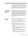
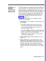
LOCAL HOST
COMPUTER ACCESS
Local host computer access allows shared use of the host
computer through Modular Processor Data Modules
(MPDMs). The MPDMs may have different data rates or
the same rate, each set to a data rate of 19,200 bps or less.
Refer to the connectivity diagram in Figure 1-13.
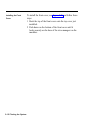
MODEM POOLS
Modem pools are groups of modems and associated
equipment used to convert digital data signals to analog
data signals or vice versa. Putting modems in pools makes
it easier for users to share a limited number of modems.
Each modem pool is used exclusively for either incoming
or outgoing calls.
Connected to Basic
Telephone Jack
The modem pool members use available basic telephone
jacks to send data between digital endpoints and remote
computers over MERLIN II system lines. Refer to the
connectivity diagram in Figure 1-14.
Connected to Analog
Station Jacks
The modern pool members use available analog station
jacks to send data between digital endpoints and remote
computers over MERLIN II system lines. Refer to the
connectivity diagram in Figure 1-15.
Connected to
Dedicated Outside
Lines
The modem pool members use dedicated outside lines to
send data betwecn digital endpoints and remote
computers. This type of modem pool would likely be used
if thcrc were many data calls to remote computers in order
to save the MERLIN II system lines for voice use. Refer
to the connectivity diagram in Figure 1-16.
1-54 System Connectivity
See Note 2
MPDM
D8W
cord
Power
Supply
■ DCP
jack
■
PFT
08
07
06
05
PFT
12
11
10
09
PFT
16
15
14
13
See Note 3
■
RS 232-C
(M25B)
MPDM
408 408 408 408 008D
PFT
04
03
02
01
DCE
interface
20
19
18
17
DCP
jack
DCE
interface
■
■
■
■
■
MPDM
■
DCP
jack
DCE
interface
Local
host
computer
■
MPDM
■ DCP
Jack
08
07
06
05
04
03
02
01
16
15
14
13
12
11
10
09
24
23
22
21
20
19
18
17
MERLIN II System
control unit
32
31
30
29
28
27
26
25
DCE
interface
■
D8W
cord
See Note 1
36
35
34
33
400B2 Adapter
D8W
cord
D8W
cord
PT 510D
PT 510D
Digital
voice
and data
Digital
voice
and data
D8W
cord
7406D with
Data Stand
See
Note 4
RS-232-C
(M25B)
Data terminal
or PC
D6AP
cord
KS-22911L1
Power supply
Notes:
1. The cable distance between the control unit and a MPDM, PT 510D, or 7406D
with data stand cannot be more than 1000 feet.
2. Some host computers act as DCE devices in which case the MPDMs will need to
be replaced with MTDMs or special wiring. If an MTDM can be used, the switch
settings are the same as an MPDM, but you don't need to set auto answer.
3. The cable distance between the MPDM or MTDM and the local host computer cannot
be more than 17 feet.
4. The cable distance between the 7406D and the data terminal cannot be more than
50 feet.
FIGURE 1-13 Simultaneous voice and data (digital station) and local host computer
access.
System Connectivity 1-55
408
Power
Supply
PFT
04
03
02
01
408
PFT
08
07
06
05
408
PFT
12
11
10
09
012
008D
36
35
34
33
16
15
14
13
D8W cord
1000' max.
Modem
pool
------------------------------MTDM
08
07
06
05
04
03
02
01
16
15
14
13
12
11
10
09
24
23
22
21
20
19
18
17
32
31
30
29
28
27
26
25
40
39
38
37
MTDM
RS-232-C
(M25B) 17 max.
2212C
Modem
2212C
Modem
-------------------------------
D4BU cord
1000' max.
MERLIN II System
control unit
FIGURE 1-14 Connectivity of a modem pool using a basic telephone module.
1-56 System Connectivity
Power
Supply
408 408 408 408 008D
PFT
04
03
02
01
PFT
08
07
06
05
PFT
12
11
10
09
PFT
16
15
14
13
D8W cord
20
19
18
17
- - - - - - - - -Modem
- - - - - - -pool
-----------M T D M
MTDM
RS-232-C (M25B)
17' max.
2212C
Modem
2212C
Modem
D4BU cord
08
07
06
05
04
03
02
01
16
15
14
13
12
11
10
09
24
23
22
21
20
19
18
17
32
31
30
29
28
27
26
25
36
35
34
33
Basic
Telephone
and Modem
Interface 2
Basic
Telephone
and Modem
Interface 2
----------------------------D8W cord
1000’ max.
MERLIN II System
control unit
FIGURE 1-15 Connectivity of a modern pool using an analog station module.
System Connectivity 1-57
Power
Supply
408 408 408 408 008D
PFT
04
03
02
01
PFT
12
11
10
09
PFT
08
07
06
05
PFT
16
15
14
13
20
19
18
17
RS-232-C (M25B)
17’ max.
/
/
-------------------------D8W cord
1000' max.
08
07
06
05
04
03
02
01
16
15
14
13
12
11
10
09
24
23
22
21
20
19
18
17
32
31
30
29
28
27
26
25
36
35
34
33
MTDM
MTDM
2212C
Modem
2212C
Modem
---------------------Modem pool
D4BU to
Central Office
line jack
MERLIN II System
control unit
FIGURE 1-16 Connectivity of a modern pool on dedicated outside lines.
GENERAL
REQUIREMENTS FOR
MODEMS
Modems are an essential part of MERLIN II system
features involving local and remote computer access. Any
modem other than the 2212C used with system hardware
should meet the following requirements to ensure proper
operation under all conditions. Modem requirements
differ according to applications. When planning the
system, remember the various modem configurations such
as a single modem for analog voice/data or modem pools.
The planning information recorded on the individual
Station Configuration forms should reflect the exact
modem arrangement for each station.
1-58 System Connectivity
The following paragraphs describe the basic requirements
for any modem, and specific requirements when used in
outgoing and incoming modem pools.
NOTE: Modems can meet these requirements through
fixed features or through hardware and software
options that can be set. An option setting may
make a modem appropriate for one pool in the
MERLIN II system but not another.
Basic Requirements
for Modems
The basic-requirements for modems are the following:
Full-duplex operation, for switched networks
●
A single speed between 300 bps and 19,200 bps
●
●
Serial transmission of characters in a binary
asynchronous format
●
EIA RS-232-C interface
Peak signal level compatible with the MERLIN II
system
Modular jack connection for telephone network
●
●
Loss of earner disconnect so that the modem goes onhook and turns received line signal detector, EIA lead
RLS (carrier on) off
●
●
●
Requirements for
Outgoing Modem
Pools
Disconnect if EIA lead DTR (data terminal ready) goes
off
Passing of break character and long space signal
Saving of options during power outage
In addition to meeting the basic requirements, a modem
used for outgoing calls must have the following
characteristics:
System Connectivity 1-59
Touch-Tone dialer that can pause and dial characters 0
through 9, #, and *
● Detection of dial tone
● Ability to take terminal dialing instructions
(compatible parity and character length with the
MTDM)
● EIA (RS 232-C) lead DSR and RLS on before a call is
placed (follows DTR)
●
Requirements for
Incoming Modem
Pools
In addition to meeting the basic requirements, a modem
used for incoming calls must have the following
characteristics:
● Auto-answer feature
●
Compatible parity and character length with MTDM
MUSIC-ON-HOLD
Music-on-Hold provides background music for callers
who have been placed on hold. It requires the use of a
music coupler. You must reserve a line jack for a music
source such as a radio, tape player, or stereo system. To
make it easier to add outside lines in the future, use the
last line jack(s) on the rightmost line module for the
Music-on-Hold connection. Refer to the connectivity
diagram in Figure 1-17.
EXTERNAL
LOUDSPEAKER
PAGING
Refer to the connectivity diagram in Figure 1-18. External
loudspeaker paging allows you to connect a single or
multizone paging system through a line jack on the
MERLIN II system. Background music can also be
provided by connecting a music coupler and a music
source.
1-60 System Connectivity
Speaker
Power
Supply
8-Ohm wire
4BU cord
408 408 408 408 408
PFT
04
03
02
01
PFT
08
07
06
05
PFT
12
11
10
09
PFT
16
15
14
13
J5
J1 (Page input)
Page Pac 20
Powermate
103A
connecting
block
PFT (Paging)
20
19
1 8 (Music)
17
J2
Music In
1 2 3 4 5 6 7 8
13
14
15
D4BU cords
4PT
5PR
08
07
06
05
04
03
02
01
16
15
14
13
12
11
10
09
24
23
22
21
20
19
18
17
32
31
30
29
28
27
26
25
40
39
38
37
36
35
34
33
Loop
start
trunk
adapter
103A
connecting
block
12345678
29R
30T
PBX
26
27
GND
124v
MERLIN II System
control unit
117 VAC
source
AC line cord
Power
supply
●
■
Standard
patch cord
Music Out
Music
coupler
Background music
■
■
Auxiliary
output
Music
source
Standard phonograph patch cord
FIGURE1-17 Connectivity of single-zone paging with Music-on-Hold.
System Connectivity 1-6
● Music in
Page Pac 20
Powermate
Page
input
J1
P1
Power
Supply
408
PFT
04
03
02
01
408
PFT
08
07
06
05
408
PFT
12
11
10
09
408
PFT
16
15
14
13
408
PFT
20
19
18
17
D4BU
cord
Switch
Page
input
Common control
unit
CK LS
DL GS
Page
port
D4BU
cord
Music
port
o
o
o
o
o
o
o
o
o
Speaker
Speaker
08
07
06
05
04
03
02
01
16
15
14
13
12
11
10
09
24
23
22
21
20
19
18
17
32
31
30
29
28
27
26
25
40
39
38
37
36
35
34
33
Speaker
D4BU
cord
● BKGND
Music
coupler
Standard
phonograph
patch cords
Music out
Music in
Music
source
MERLIN II System
control unit
FIGURE 1-18 Connectivity of multizone paging with background music and
Music-on-Hold.
1-62 System Connectivity
Section 2: installation
Preinstallation Requirements
2-1
Reviewing the Planning Forms
Environmental Requirements
Spare and Location Requirements
Power Requirements and Secifications
Grounding Requirements
Wire Length Limitations
Wall Attachment Requirements
2-1
2-1
2-2
2-2
2-3
2-3
2-4
System Grounding Requirements
2-5
System Ground Connection
AC Outlet Tests
CO Line Protector
Surge Protectors
IROB Protectors
Static Discharge Problems
Radio-Frequency Interference
Wiring the System
2-5
2-7
2-8
2-8
2-9
2-9
2-9
2-12
Typical MERLIN II System Wiring
Module Jacks
2-12
2-14
Outside Line Wiring
Preparing the Network Interface
Testing the Outside Lines
Connecting Outside Lines to the Control Unit
Tie Line Module Wiring
2-17
2-17
2-19
2-19
2-21
Voice Terminal Wiring
Connecting Voice Terminal Wiring to the Control Unit
Wiring a Voice Terminal for Two Voice-Pairs
Standard 4-Pair Wiring
2-23
2-23
2-27
2-30
Jack Field Wiring
Constructing a Jack Field for Voice Terminal Wiring
Connecting Voice TerminaI Wiring to a Jack Field
Extending the Network Interface to a Jack Fieid
for Outside Lines
2-41
Wiring Reference Tables
2-45
Installing the Control Unit
2-33
2-35
2-37
2-50
Control Unit Components
Mounting the Basic Carrier
Mounting the Expansion Carrier
Determining Unit Load Requirements
Determining Module Slot Assignments
2-50
2-52
2-56
2-57
2-61
Module Installation
Installing a Module
Removing a Module
Insralling the Power Supply Module
Installing the Auxiliary Power Unit
Installing the Feature Module on the Processor Module
Installing Line and Station Modules
Connecting a Printer to the ControI Unit
Connecting the Control Unit to an AC Outlet
Power to the System
2-62
2-63
2-64
2-66
2-72
2-73
2-79
2-81
2-90
2-90
Connecting the Voice Terminals
Assembling the Voice Terminals
Connecting Voice Terminals to the System
Testing the Voice Terminals
Labeling Each Voice Terminal
Connecting the Power Failure Telephone
Testing the PFT Jacks
2-92
2-93
2-95
2-95
2-96
2-97
2-99
Testing the System
2-100
Testing the Voice Terminal Jacks for a Dial Tone
Testing Intercom Calls
Testing Outside Lines
Testing Tie Lines
2-100
2-101
2-103
2-104
Completing the Installation
Attaching the Control Unit Covers
2-106
2-106
Modifying the System
2-112
Adding an Outside Line
Adding a Voice Terminal
Moving a Voice Terminal
2-112
2-113
2-115
Adding Accessories
2-117
General Accessories
Power Accessories
2-117
2-122
Upgrading an Existing System
Site Preparation
Get a Printout of the Existing System
Upgrade Instructions FMl or FM2 to R3
Upgrade Instructions FMl to FM2
2-131
2-131
2-132
2-133
2-136
Preinstallation Requirements
REVIEWING THE
PLANNING FORMS
Review the completed system planning forms, which
should be on site, before starting installation. The forms
for Release 3 are titled:
● Form la, System Form—Incoming Lines
● Form 1b, System Form—Tie Lines
● Form 1c, System Form—Module Identification
Diagram
● Form 1d, System Form—Station Planning
● Form 1e, System Form—Requirements and Options
The forms for Feature Modules 1 and 2 are titled:
● Master Planning Form
● System Configuration Form
You should be familiar with the entire layout of the system
including wiring, jack field, network interface, and
accessory requirements. If the system has data hardware,
see the separate manual, MERLIN II Communications
System Data Communications Guide, for complete
instructions for installing data equipment.
ENVIRONMENTAL
REQUIREMENTS
The control unit should be operated in an environment that
meets the following conditions.
● Operating temperatures. The operating temperature
0
0
should be 40 to 104 F (4 to 40
C). Optimum
0
operating temperature is 60 F.
● Humidity. The humidity should be between 20 and 80
percent.
● Airborne contamination. Do not expose the control
unit to moisture, corrosive gas, dust, chemicals, spray
paint, or similar material.
Preinstallation Requirements 2-1
WARNING: The
control unit cannot be installed
outdoors. It must be installed in an environment
suitable for electronic equipment. Do not expose the
control unit to devices that generate electrical
interference such as arc welders or motors.
SPACE AND
LOCATION
REQUIRIEMENTS
The control unit should be located with the following
points in mind:
●
CO line protection. The control unit should be
installed near the Central Office line protectors
provided by the local telephone company. Refer to
“System Grounding Requirements” on page 2-5 for
additional information about line protection.
Ventilation. Allow at least 1 inch of space on the right
●
and left sides of the control unit and 12 inches of space
above and below the control unit to prevent
overheating. Do not place the control unit near
extreme heat or in direct sunlight.
Placement. AIlow at least 1 foot of space to the right
●
of the basic carrier for expansion and at least two feet
of space to the left for a jack field. Refer to “Wiring
the System” on page 2-12 and “Jack Field Wiring” on
page 2-33 for additional information on space
requirements.
POWER
REQUIREMENTS
SPECIFICATIONS
Listed below are the power requirements and
specifications for the control unit:
●
Voltage range. 99 to 129 VAC
Voltages generated by the power supply remain within
specification for an ac line voltage low of 99 VAC.
The system will bridge a 40 millisecond supply outage
without dc voltages being affected.
2-2 Preinstallation Requirements
●
Frequency range. 60 Hz +/- 1 percent
●
Max. current. 3 amperes per power supply
●
Max. power use. 225 watts per power supply
GROUNDING
REQUIREMENTS
The system must be connected to a properly grounded ac
outlet. See page 2-5, “System Grounding Requirements,”
for more information.
NOTE: If Modular Processor Data Modules, Modular
Trunk Data Modules, or moderns are to be
installed at the control unit location, additional
grounded ac outlets will be needed.
WIRE LENGTH
LIMITATIONS
Wires connected to the control unit should consist of a
single continuous run, i.e., without extension cords or
other splices, and should meet these specifications:
Power cord. The power cord must be less than 6 feet,
and must be connected to a properly grounded ac
outlet that is not switch-controlled.
Incoming lines. The distance from the network
interface provided by the local telephone company for
incoming lines must be spanned within one cord length
(generally 25 feet or less).
Jack field. The distance to the jack field mounted to
the left of the carrier must be within cord length.
Station. Each voice terminal must be within 1000 feet
of the control unit.
WARNING: If a voice terminal is used for In-Range,
Out-of-Building (IROB) applications, IROB
protectors are required. See “IROB Protectors” on
page 2-126 for more information.
Preinstallation Requirements 2-3
WALL ATTACHMENT
REQUIREMENTS
The customer should have a backboard mounted at the
control unit site. If one is not in place, you may need to
attach a backboard to the wall. The backboard should
meet these specifications:
● It should be made of 3/4-inch thick plywood.
It should be 4 feet wide by 2 feet high in order to
accommodate a basic control unit with an expansion
carrier and jack field. If ample wall space is available,
use a backboard that is 4 feet by 4 feet, regardless of
the system’s size. This size provides enough space for
future expansion.
● It should be attached to the wall with hardware that has
a combined pull-out force of at least 500 pounds.
Determine the type of mounting surface on which the
board is to be mounted, and refer to Table 2-1 for
recommended hardware.
●
TABLE 2-1 Backboard Mounting Hardware
Mounting surface:
Hardware required:
Wood
Wood screws
Concrete
Brick
Cinder block
Masonry anchors
Plaster
Plasterboard
Toggle bolts
Sheet metal
Sheet metal screws
2-4 Preinstallation Requirements
System Grounding Requirements
Proper grounding of the installation site is fundamental to
protect the MERLIN II communications system against
these types of electrical discharges:
●
Lightning strikes near the
●
Power surges
●
Power crosses on Central
●
Static discharge
The following procedures serve as electrical safety
requirements and guidelines in grounding. Apply them as
you install the MERLIN II system.
Make sure these requirements are satisfied
before applying power to the system.
WARNING:
SYSTEM GROUND
CONNECTION
The control unit the CO line protector, and the ac power
service panel should be as close to each other as possible.
The adequacy of lightning protection is a direct function
of the distance between these pieces of equipment.
Recognizing that equipment may be spread throughout a
building, the National Electric Code (NEC) requires that
the ground point for the CO line protector be bonded to the
ac power ground. Proper grounding helps prevent
equipment damage due to lightning energy and/or power
transients conducted into the equipment via CO and ac
power lines.
It is the responsibility of the local telephone company to
provide protection of Central Office lines at the entrance
to the site. The protection should consist of the following:
●
Carbon blocks or gas discharge tubes connected to an
approved ground
System Grounding Requirements 2-5
Adequate bonding of the Central Office line protector
ground and the power company ground
Refer to Figure 2-1 for an example of a typicaI MERLIN II
system grounding plan.
●
MERLIN II System
control unit
408 408 408 408
Power
Supply
To
Central
Office
CO
lines
CO
line
protector
●
- -
Plug
AC
surge
suppressor
AC
outlet
Commercial
power
●
Shield
ground
B
W
GND(Green) ●
Power
service
●
Earth
ground
Bond wire
Power
ground
rod
FIGURE 2-1 A typical MERLIN II system grounding plan.
2-6 System Grounding Requirements
●
AC OUTLET TESTS
The following tests verify proper grounding of the ac
outlet.
Hazardous voltages are present during the
following tests. Use great care when working with ac
power line voltages.
WARNING:
Check the ac outlet for proper ground with a circuit tester.
NOTE: You may use any generic unit (such as the Ideal
61-035 Circuit Tester) to verify that the outlet is
wired properly.
1 Plug an Ideal or equivalent circuit tester into the outlet
to be tested. If the circuit is properly grounded, the
yellow and white lights on the tester will light.
2 Remove the circuit tester and, if necessary, test another
outlet.
NOTE: If the ac outlet test shows an improper ground, do
not install the MERLIN II system. Tell the
customer to have an electrician correct the
problem.
Check the ac outlet for proper ground with a Volt-OhmMilliammeter (VOM).
1 Set the VOM to the scale on which you can read 115
VAC.
2 Measure the ac outlet voltages:
> Hot to third-wire ground should be about 115
VAC.
> Neutral to third-wire ground should be less than
2.5 VAC.
3 If the voltage readings do not measure the values
suggested, the ac outlet is improperly wired. Notify
the customer that an electrician should repair the
outlet.
System Grounding Requirements 2-7
CO LINE PROTECTOR
The following test can be used to check CO line protector
grounding. This test does not check the bond between the
power company and telephone company protector
grounds.
1 Connect a craft test set between the protector ground
lug and the ring side of the CO line.
2 If a dial tone is present, the protector is grounded.
3 If a dial tone is not present, the protector is not
grounded; call the local telephone company. Request
that they properly-ground and bond the CO line
protector to ac power ground.
SURGE
PROTECTORS
If the CO line protector is properly grounded and bonded
to the ac power ground, most lightning damage will be
prevented.
Both the ac line and CO line parts of the 147A Protector
are available as separate units. The ac line component is
available as the 145A AC Surge Protector. For installation
instructions, refer to CIB 3110, which is included with the
component. The central office line component is available
as the 146A CO Line Protector. Installation instructions
for the 146A CO Line Protector are available in CIB 3111,
which is included with the device.
A 147A Protector provides additional protection from ac
and CO line power surges. If the line module’s apparatus
code contains the letter “A” (517A1, 517A2, or 517A4),
use the 147A Protector for surge protection. If the line
module’s apparatus code contains the letter “B” (517B1,
517B2, or 51734), use a 145A Protector. Modules with
the “B” designation have CO line protection built in, but
not ac line protection.
For installation and user instructions, refer to Customer
Instruction Booklet (CIB) 3109, which is included with
the 147A Protector.
2-8 System Grounding Requirements
IROB PROTECTORS
Equipment that is connected to the analog station jacks
(408/008) and is located in a building outside of the main
(control unit location) building, but within 1000 feet of the
control unit is called In-Range, Out-of-Building (IROB)
equipment. To protect both the control unit and the IROB
equipment from exposure to lightning, inadvertent contact
with power lines, and power currents induced by nearby
power lines, IROB Protectors are required. Two TII
Model M343 IROB protectors are required for every analog
station jack that is connected to IROB equipment. The
IROB protectors must be located at the cable entrance/exit
of both buildings. See “IROB Protectors” on page 2-126
for more information.
TIE LINE
PROTECTION
Local tie lines that extend out-of-building must have
primary protection in the form of voltage limiters
(typically carbon blocks or gas tubes). A protector should
be provided in each building where the wiring run leaves
or enters.
STATIC DISCHARGE
PROBLEMS
The MERLIN II system contains components that can be
damaged by electrostatic discharge. To prevent static
discharge, take these precautions:
1 Properly ground yourself when replacing modules or
performing other tasks on the control unit.
2 Have the customer maintain relative humidity between
20 and 80 percent.
3 Have the customer install an antistatic mat at each
voice terminal.
RADIO-FREQUENCY
INTERFERENCE
In most cases, radio-frequency interference (RFI), or
electrical noise, is introduced to the system through trunk
or voice terminal cables. However, electromagnetic fields
near the control unit may also cause RFI in the system.
Therefore, the control unit and cable runs should not be
System Grounding Requirements 2-9
placed in areas where a high electromagnetic field
strength exists. Leading causes of interference include
AM and FM radio station transmitters, television station
transmitters, induction heaters, and motors (with
commutators) of 0.25 horsepower (200 watts) or greater.
Small tools with universal motors are generally not a
problem when they operate on separate power lines.
Motors without commutators generally do not cause
interference.
Field strengths below 2 volts per meter are unlikely to
cause interference. Field strength can be measured by a
tunable meter such as the Model R-70 meter manufactured
by Electro-Metrics Division, or broadband meters such as
the HOLADAY™ HI-3001 meter or Model EFS-1 meter
manufactured by Instruments for Industry, Inc.
You can estimate the field strength produced by radio
transmitters by dividing the square root of the emitted
power in kilowatts by the distance from the atenna in
kilometers. The result yields the approximate field
strength in volts per meter and is relatively accurate for
distances greater than about half a wavelength (150 meters
for a frequency of 1000 KHz).
Solutions to RadioFrequency
Interference Problems
To reduce or eliminate radio-frequency interference
problems from nearby induction heaters or 0.25
horsepower motors, either move the equipment causing
the problem or move the MERLIN II system control unit
to a different location.
To reduce or eliminate radio-frequency interference
problems from nearby radio station antennas, choose from
among the following solutions:
● Do not run MERLIN II system station wire in the same
conduit as ac cable, or next to ac circuits if the station
wire is exposed. If possible, do not cross station wire
2-10 System Grounding Requirements
●
●
●
●
over ac circuit wire. When crossing station wire over
ac circuits is unavoidable, try to maintain a 3-foot
clearance.
Use conduit for wiring runs whenever possible. Be
sure that the conduit is grounded. If the conduit is not
grounded, run a No. 12 wire from the conduit and
terminate it on the ac earth ground, or bond it to the
earth ground.
Run station wire on the baseboard or as close to the
floor as possible.
Run shielded wire for the stations that are having
interference problems. Ground the shield of the wire
and bond it to the ac ground.
Visually verify that the ac power line is grounded and
that it is bonded to the protector ground. Use an Ideal
circuit tester (or equivalent) or a VOM to verify that
the ac outlet is grounded. (See “AC Outlet Tests” on
page 2-7.) If the outlet is not grounded, run a No. 12
wire from either the grounding terminal or the center
screw of the ac outlet to the location where the ac
power line is earth grounded, and terminate it.
Install Built-in speakerphone stations (BIS-10, INS-22,
BIS-34).
●
●
●
●
Install a Z200A filter at the MERLIN II system station.
If interference is still present, install another Z200A
filter at the control unit.
If there is radio interference on the CO lines, use a
ZIOOA filter.
Change the ac outlet to a different branch circuit.
Move the control unit to a different location.
System Grounding Requirements 2-11
Wiring the System
TYPICAL MERLIN II
SYSTEM WIRING
2-12 Wiring the System
Figure 2-2 illustrates typical MERLIN II system wiring.
Central office lines enter the site through a 25-pair cable.
The network interface in this example is a 66-type block
configured as an RJ21-X-type connector. From the
network interface, a DIW cable takes the 25 lines to a jack
field for outside lines. The jack field interfaces the
outside line wiring with D2R cords that plug into the line
jacks on the control unit modules. At this point, outside
lines are connected to the control unit.
The station side of the control unit goes to a jack field for
voice terminals through D8W cords. The other side of the
jack field goes to the 102A connecting blocks through 4pair DIW cable. The voice terminals plug directly into the
connecting blocks through four-pair modular cords.
(Jack field
for outside lines)
Central
office
lines
RJ21-X
interface
25 Pair cable
Power
Supply
DIW cable
D2R cords
Z122C Box
With
Z610A
Adapters
408 408 408 408 408
Outside
lines
PFT
04
03
02
01
PFT
08
07
06
05
PFT
12
11
10
09
PFT
16
15
14
13
PFT
20
19
18
17
(Jack field
for voice
terminais)
08
07
06
05
04
03
02
01
16
15
14
13
12
11
10
09
24
23
22
21
20
19
18
17
32
31
30
29
28
27
26
25
40
39
38
37
36
35
34
33
Z122C Box
4-Pair
DIW cords
with Z610A
adapters
D8W
cords
Station
lines
MERLIN II System control unit
102A
102A
D8W cord
Voice
terminal
Office 1
D8W cord
Voice
terminal
102A
102A
Office 2
D8W cord
Office 3
Voice
terminal
D8W cord
Office 4
Voice
terminal
FIGURE 2-2 Typical MERLIN II system wiring installation.
Wiring the System 2-13
MODULE JACKS
There are various types of jacks on the line and station
modules (Figure 2-3). Each type of jack has a specific
function as follows:
●
Analog station jacks. These jacks are for analog
voice terminals, analog data devices, and accessories.
●
●
●
●
2-14 Wiring the System
Basic telephone jacks. These jacks are for basic
telephones with Touch-Tone or rotary dial capability.
Do not connect MERLIN II system analog voice
terminals to basic telephone jacks.
Digital station jacks. These jacks are for digital voice
terminals, digital voice/data sets, MPDMs, MTDMs,
etc.
Outside line jacks. These jacks are for outside lines
provided by the local telephone company. You can
also connect an optional loudspeaker paging device
and/or music source to any of these jacks.
Power Failure Telephone (PFT) jacks. These jacks
are for basic telephones only. In case of a power
outage, basic telephones plugged into these jacks
become operational. They do so by bridging onto the
lowest line of the group of four line jacks with which
they are associated. Do not use MERLIN II system
voice terminals as power failure telephones.
Tie line jacks. These jacks are for a transmission
facility dedicated to interconnect two private switching
systems.
PFT jack
Switch
Outside Iine
jacks
Tie line
jacks
Analog station
jacks
Tie line
jacks
Analog station
jacks
Switch
400EM
408
0 0 8
FIGURE 2-3 Line and station module jacks.
Wiring the System 2-15
PFT jack
Outside iine
jacks
Outside line
jacks
Outside line
jacks
PFT jack
PFT jack
8 0 0
400 w/DTMF
Outside line
jacks
Basic
telephone
jacks
Digital station
jacks
012
008D
FIGURE 2-3 line and station module jacks (continued).
2-16 Wiring the System
Outside Line Wiring
PREPARING THE
NETWORK
INTERFACE
The local telephone company provides the telephone
numbers for outside lines, as well as an installed network
interface that may consist of 1-Line adapters (RJ11-type),
2-line adapters (RJ14-type), or 25-line (50-pin, RJ21-type)
connectors.
You can connect the outside lines from the network
interface connector to the control unit using D2R cords.
The method used to connect the outside lines to the
control unit depends on the type of network interface as
follows:
●
1-line adapter (RJ1l-type). This adapter allows one
connector for each outside line.
> Label each jack with the telephone number.
● 2-line adapter (RJ14-type). This adapter connects
two outside lines per jack.
> Label each jack with the telephone numbers of its
two outside lines.
> Plug a 2-line adapter (267C-type) into each jack.
●
50-pin connector (RJ21-type). This connector carries
up to 25 lines.
> Label the interface with the numbers for the
outside lines.
> To extend the network interface to the jack field,
refer to the instructions in “Jack Field Wiring” on
page 2-33.
Refer to Figure 2-4 for examples of network interfaces and
adapters.
Wiring the System
2-17
Single-line
adapter (RJ11)
2-Line adapter
(RJ14)
(267C)
66-Type block (RJ21-type) 25 line interface
Line 1
Line
Line
2
3
Line 4
Line 5
Line 6
Line 25
FIGURE 2-4 Network interface adapters.
2-18 Wiring the System
Line
Tip
Ring
Phone Number
1
1
26
555-3827
2
2
27
555-3828
3
3
28
555-3829
●
●
●
● ● ●
●
●
●
● ● ●
25
25
50
555-3851
TESTING THE
OUTSIDE LINES
You often need to test an outside line at the network
interface or jack field. This test will verify that the outside
telephone lines are working properly. To perform this test,
you-need a basic rotary dial telephone and a Touch-Tone
telephone, each with a modular cord, or two craft sets.
Do not use a MERLIN II system voice
terminal for testing. It does not work for this test, and it
can be damaged if you use it for this purpose.
CAUTION:
1 Bring the Basic telephones or craft set to the jacks for
the outside lines (either at the network interface or at
the jack field).
2 Plug the telephone’s modular cord or the craft set’s
cord into an outside line jack and listen for a dial tone.
3 Dial a known telephone number with each basic
telephone or the craft set to verify both rotary and
Touch-Tone dialing.
4 Call each outside line jack with a basic telephone or
craft set to verify ringing.
5 Repeat steps 2 through 4 for each outside line.
CONNECTING
OUTSIDE LINES TO
THE CONTROL UNIT
You need the following items to connect the control unit
to the jacks for the outside lines, whether they appear at
the jack field or at the network interface.
●
Outside line numbers label. This label is for listing
each outside line number connected to the system with
its corresponding jack number. The label is packed
with the installation kit and it should be pasted on the
inside front cover of the control unit or the inside of
the left door of the jack field box containing the
outside lines.
Wiring the System 2-19
●
Single-pair modular line cords. You need one D2R
cord for each outside line. The cord must be long
enough to reach the network interface.
● Green line-cord labels. These labels are marked 01,
02, 03, etc. You need a matching pair for each line
cord.
● Outside line numbering strips. These labels are used
to number all the line jacks on the modules themselves.
You can have up to 56 outside line jacks with the
MERLIN II system. The numbering sequence is 01 to 56.
To connect the outside line wiring, follow these steps:
1 Review Form 1a, System Form-lncoming Lines for
Release 3, or the Master Planning Form for Feature
Modules 1 and 2, to determine each outside line
assignment on the control unit.
The outside line numbers are the telephone numbers
listed at the network interface or inside the left door of
the box in the jack field containing the jacks for your
outside lines.
2 Number sequentially from 01 to 56 every outside line
jack on the modules using the outside line numbering
strips. Begin with the module in slot 1, numbering
from bottom to top and working from left to right
across the control unit (See Figure 2-2 on page 2-13
for the numbering sequence.)
Refer to Figure 2-3 on pages 2-15 and 2-16 to identify
those modules that have line jacks and locate the
positions the line jacks occupy on those modules.
3 Connect the outside line jacks on the modules to the
network interface using D2R cords. Thread the wires
through the wire managers at the base of each module
as you connect the wires to the jacks. Label each end
of each cord with the outside line jack number to
which each is connected.
2-20 Wiring the System
4 Write the telephone number assigned to each of the
line jacks next to the number for that line jack on the
outside line numbers label found on the inside of the
control unit’s front cover or on the inside of the left
door of the jack field box containing the outside lines.
WARNING: National
and local building codes specify
the type of cable required for telecommunication
wiring. For example, indoor wiring (DIW) cannot be
used inside or on top of air plenums or ducts, along hot
pipes; or across walkways. Consult your local
ordinances and regulations for proper cable selection.
If staples are used to attach the cords to walls or
baseboards, check that the cords have not been pierced.
Also, do not run Central Office lines from the network
interface to the control unit if the distance if greater
than 25 feet.
TIE LINE MODULE
WIRING
The interface from the Tie Line Module to the network
facility is provided through modular jacks. Each modular
jack provides an electrical interface to the network that
consists of six leads: T (pin 5) and R (pin 4) are for
outgoing analog transmission; T1 (pin 1) and R1 (pin 2)
are for incoming analog transmission; and E (pin 3) and M
(pin 6) are for signaling. Figure 2-5 shows how to connect
the Tie Line Module to the network interface.
The protected mode must be used
whenever the E&M leads extend out-of-building and
are not connected to the network interface. See pages
1-47 and 1-48.
WARNING:
Wiring the System 2-21
Power
Supply
408 408 408 408 400
EM
25 pair
cable
D8W
cord
T (5)
R (4)
T1 (1)
R1 (2)
E (3)
M (6)
Z601A
Adapter
RJ2GX
26
1
27
2
28
3
T
R
T1
R1
E
M
To
Network
and
Facility
Signaling
Equipment
Z601A - Adapter
Jack Position
1
2
3
4
5
6
7
8
Connector Position
3
4
5
2
1
6
7
8
MERLIN II System
control unit
Power
Supply
408 012 DCP 408 400
EM
D8W cord
D8W cord
356A
Adapter
D8W cord
D8W cord
MERLIN II System
control unit
FIGURE 2-5 Tie Line Module wiring.
2-22 Wiring the System
25 pair
cable
RJ2GX
T (5)
R (4)
T1 (1)
R1 (2)
E (3)
M (6)
26
1
27
2
28
3
T
R
T1
R1
E
M
To
Network
and
Facility
Signaling
Equipment
Voice Terminal Wiring
CONNECTlNG VOICE
TERMINAL WIRING
TO THE CONTROL
UNIT
You can connect up to 120 station jacks, which support up
to 120 voice terminals in the MERLIN II system.
NOTE: The terms “voice terminal” and “station” are
synonymous when describing the wiring and
labeling of the voice terminal side of the
MERLIN II system.
Up to 60 stations can be connected with the Voice
Announcement to Busy Voice Terminal or Simultaneous
Voice and Data features. Both of these features require
the use of two adjacent odd/even jacks on the control unit
for each station that is connected with the feature.
Because they require two voice-pair wiring, use of either
of these features decreases the system’s voice terminal
capacity. See “Wiring a Voice Terminal for Two VoicePairs” on page 2-27.
NOTE: The default intercom numbers (10 through 69 and
700 through 759) should not be confused with the
station jack numbers (01 through 120) that
identify the sequential station jack locations on
the modules. Intercom 10, for example, is
located in the first station jack on the first station
module of the control unit, labeled 01. The
“odd/even” in this type of wiring refers to jack
numbers, not intercom numbers.
You can connect the voice terminal locations either
directly, with modular voice terminal cords, or through
building wiring to a jack field at the control unit location.
Jack field wiring is the recommended method for
installations with more than 30 stations. Direct
connection is recommended for installations with fewer
than 30 stations. Determine which method to use to
connect the voice terminal wiring to the control unit and
follow the appropriate instructions below under
“Connecting Voice Terminal Wiring Through a Jack
Field” or “Connecting Voice Terminal Wiring Directly.”
Wiring the System 2-23
Refer to “Jack Field Wiring” on page 2-33 for instructions
on how to construct a jack field. You need the following
items to complete the connections:
● System directory label. Use this label to record the
end locations of each intercom number in the system.
●
Blue station-cord labels. These labels come in pairs
with the basic and expansion carrier and are used to
identify cable runs. The first sheet of labels is
numbered 01 through 69 and is shipped with the basic
carrier. The second sheet is numbered 70 through 120
and 700-759. This sheet is packed with the expansion
carrier. You should have a matched pair of labels for
each line cord.
●
●
●
4-Pair modular jumper cords. These cords are for
jack field connections. You should have one cord for
each voice terminal in your system.
System Labels. These labels, used to number jacks,
are shipped with the feature module. They are
numbered 1 through 56 for lines and 01 through 120
for stations.
Line Cable Numbering Labels. These green labels
come in pairs and are numbered 01 through 56.
Connecting Voice
Terminal Wiring
Through a Jack Field
To connect the station wiring through a jack field, perform
the following steps:
1 Number every station jack on the modules sequentially
from 01 through 120, using the station numbering
strips. Begin with the module in slot 1, and number
from bottom to top, then continue from left to right
across the control unit (See Figure 2-2 on page 2-13.)
You may want to review Figure 2-3 on pages 2-15 and
2-16 to identify which modules have station jacks and
locate the positions of the station jacks on each
module.
2-24 Wiring the System
2 Wire the station jacks on the modules to the jack field
using D8W cords. Thread the wires through the wire
manager located at the base of each module as you
connect them to the station jacks. Label each end of
each wire with the intercom number to which it
connects. Remember, the intercom numbers do not
necessarily match the jack numbers. Intercom 10, for
example, is connected to station jack 01 on the first
station module of the control unit.
3 Record the end location of each intercom number on
the system directory label and put this label on the
inside of the front cover of the control unit.
Complete wiring instructions for data stations are found in
the separate document, MERLIN II Communications
System Data Communications Guide.
Connecting Voice
Terminal Wiring
Directly
To connect the voice terminal locations directly to the
control unit, perform the following steps:
1 Number every station jack on the modules sequentially
from 01 through 120, using the station numbering
strips. Begin with the module in slot 1 and number
from bottom to top; then go on to the next module with
station jacks, working from left to right across the
control unit modules.
You may want to review Figure 2-3 on pages 2-15 and
2-16 to identify which modules have station jacks and
locate the positions of the station jacks on each
module.
2 In the system directory, fill in the voice terminal
location you have selected for each intercom number.
Wiring the System
2-25
3 Beginning with a pair of labels marked 01, label each
cord at both ends with matching labels.
If the distance between a voice terminal location and
the control unit requires the use of extension cords,
label each end of the wiring run. Attach one label near
the plug to the voice terminal and the matching label
near the plug to the control unit.
4 Run cords from the voice terminal locations to the
control unit.
CAUTION: Do not run cords inside air plenums or
ducts, along hot pipes, or across walkways. If you
use staples to attach cords to walls or baseboards,
be careful not to pierce the cords. If there are one
or more In-Range Out-of-Building voice terminals
to be installed, be sure to use two IROB protector
for each lROB voice terminal.
5 Thread each cord through the wire manager of the
control unit and up to the voice terminal jack with the
same number as the cord label, and plug it in. For
Release 3, refer to Form 1d System Form-Station
Planning; for Feature Module 1 or 2, refer to the
Master Planning Form to check the intercom number
assignments against the voice terminal jack locations.
Intercom 10, for example, is connected to the voice
terminal jack labeled 01 at the first jack location of the
first station module in the control unit.
2-26 Wiring the System
WIRING A VOICE
TERMINAL FOR TWO
VOICE-PAIRS
If an analog voice terminal requires either the Voice
Announcement to Busy Voice Terminal feature or the
Simultaneous Voice and Data feature, you need to assign
two adjacent odd/even station jacks (01 and 02, 13 and 14,
etc.) on an analog station module to that voice terminal.
For Release 3, Form 1d, System Form-Station Planning
shows which stations receive either option. For Feature
Modules 1 and 2, the Master Planning Form gives this
information. The numbers of the station jacks to which
each of these stations should be connected are boxed on
the form.
The wiring requirement for either of these features is that
two voice-pairs (one pair from each jack) must be
connected from the control unit to the voice terminal.
Refer to Figure 2-6 for an example of wiring a voice
terminal for adjacent odd/even jacks. In this example, a
bridging adapter (BR-241-B1) is used to connect both
voice pairs to the voice terminal.
Note that in Figure 2-6, the wire from station jack 39 on
the line module connects to the jack labeled “Even” on the
bridging adapter. This is because the label on the bridging
adapter refers to the default intercom number, which does
not necessarily match the station jack number in terms of
odd and even. Odd/even wiring refers to jack numbers,
not intercom numbers.
Wiring the System
2-27
408 408 408 408 408
Power
Supply
CO
lines
PFT
04
03
02
01
PFT
08
07
06
05
PFT
12
11
10
09
PFT
16
15
14
13
PFT
20
19
18
17
Adjacent
odd/even
jacks
0
0
0
0
0
0
0
0
8
7
6
5
4
3
2
1
1
1
1
1
1
1
1
0
6
5
4
3
2
1
0
9
24
23
22
21
20
19
18
17
32
31
30
29
28
27
26
25
40
39
38
37
36
35
34
33
Bridging
Adapter
(BR-241-B1)
(See Note)
D8W cords
Even
Station
(Voice terminal)
Odd
Line
Voice
terminal
MERLIN II System
control unit
Note:
For bridging adapter, ‘even” and "odd" refer to default intercom numbers. These numbers
do not necessarily match jack numbers in terms of odd and even.
FIGURE 2-6 Wiring a voice terminal for adjacent odd/even jacks using a bridging
adapter.
The bridging adapter is one method of wiring two voice
pairs to a voice terminal (adjacent odd/even jacks). The
electrical connections made by this adapter are shown in
Figure 2-7.
2-28 Wiring the System
MERLIN II System
control unit
Odd numbered jack
(Even numbered
station)
Bridging adapter
Even numbered jack
(Odd numbered
station)
Station (Voice
Terminal)
Voice
terminal
Even
Line
Odd
O O O O O O O O
R T R T R T R T
4 4 3 1 1 3 2 2
O O O O O O O O
R T R T R T R T
4 4 3 1 1 3 2 2
8
Odd station jack from
control unit
7
6
5
4
3
2
To voice terminal
1
O O O O O O O O
R T R T R T R T
4 4 3 1 1 3 2 2
5
4
Even station jack from
control unit
Top
Front
BR241-B1
STATION
6
pins
8
pins
2
pins
87654321
Typical 8-position jack
FIGURE 2-7 A wiring diagram of the bridging adapter for adjacent odd/even jacks.
Wiring the System
2-29
STANDARD 4-PAIR
WIRING
2-30 Wiring the System
If you are wiring for 4-pair using a 66-type block, review
the diagram in Figure 2-8. Notice that the wiring for the
additional voice pair (the even-numbered jack) terminates
in the same place on the building wiring block as the
wiring for the odd-numbered jack. The brand Rex adapter
(BR 866-JC) attaches to the block over all four pairs and
provides a modular jack for a connection to the control
unit.
Brand Rex part #
BR866-JC
Standard 8-pin
jack wiring
1 — T2 –
R 2–
T 3–
R 1–
T 1–
R 3–
T 4–
8 — R4 –
–
–
–
–
–
–
–
–
–
–
–
–
–
–
–
–
–
–
–
–
–
–
–
–
2 T— 1
2 R
3 T
1 R
1 T
3 R
4 T
4 R— 8
66-Block free of building
wiring; needed for jumpers
Odd number CM jacks
to be affixed to
building wiring block
To
previous
even
number
port used
per
— 1
R1
T1
— 8
66-Block wired for
four-pair station runs
Even number CM jacks
from which to run jumpers
FIGURE 2-8 A 66-type block wired for 4-pair station runs.
Wiring the System 2-31
Follow the diagram in Figure 2-9 if you are performing a
postwire surface-mounted application or if you are using
apparatus boxes in a jack field.
The postwire surface-mounting requires a 104A
connecting Block. Two 4-pair modular cords coming
from the control unit (adjacent odd/even jacks) plug into it
and the voice pairs from each connect to the wires of a
single 4-pair modular cord. The voice terminal plugs
directly into the modular cord and then has the use of the
two voice pairs.
If you are using the Z122C apparatus boxes, you need to
provide two Z601A adapters for each terminal that
requires two voice-pairs. A single 4-pair cord can then be
run from the jack field to the voice terminal that requires
two voice-pairs.
2-32 Wiring the System
Even port
Odd port
1 — — T1
T 1— — 1
R 1— — 2
2 — — R1
T 2— — 3
3 — — T2
R 2— — 4
4 — — R2
T 3— — 5
5 — — T3
R 3— — 6
6 — — R3
T 4— — 7
R 4— — 8
7 — — T4
8 — — R4
110-Type standard
8-pin wiring
O O O O O O O O
R 4 T 4 R 3 T 1 R 1T 3 R 2 T 2
8 7 6 5 4 3 2 1
Voice terminal
Note:
If ZI22C apparatus boxes are used, two Z601A adapters are required per terminal.
FIGURE 2-9 104A Connecting Block hardware wired for 4-pair station runs.
Jack Field Wiring
The following information describes how to construct a
jack field for voice terminal wiring at the control unit and
how to connect the jack field to the voice terminals
through the building wiring. It also explains how to move
Wiring the System 2-33
the point of connection to the outside lines from the
network interface, which is provided by the local
telephone company, to jacks in a jack field for the outside.
lines.
Refer to the topics referenced below depending on your
wiring needs.
If you decide not to have direct connections from the
voice terminals to the control unit and the building
wiring and jack fields are not installed, you need to
construct a jack field for the voice terminal wiring.
Follow the instructions in “Constructing a Jack Field
for Voice Terminal Wiring,” found on page 2-35.
● If the local telephone company provided a 50-pin
(RJ2 l-type) connector interface but the wiring from
the network interface to a jack field for outside lines is
not installed, you may want to construct a jack field for
outside line wiring and extend the network interface to
it. Follow the instructions in “Extending the Network
Interface to the Jack Field for Outside Lines” on page
2-41.
● If all necessary wiring is in place, go on to “Installing
the Control Unit” on page 2-50 and follow the
instructions.
See Figure 2-2 on page2-13 for an illustration of
MERLIN II system wiring with jack fields.
NOTE: The jack fields for the system shown are
constructed with Z122C apparatus boxes, which
are attached to each other using a tongue-ingroove design and mounted to the left of or under
the control unit. The Z122C boxes come with 2A
retainers for holding wiring adapters, such as the
cutdown-to-modjack 2601A adapter. If 2A
retainers are not required, Z122B apparatus
boxes can also be used. See the following
heading, “Constructing a Jack Field for Voice
Terminal Wiring.”
●
2-34 Wiring the System
You may also decide to connect the outside wiring
directly from the network interface to the control unit and
the voice terminal wires directly from the voice terminal
locations to the control unit. If the installation is simple or
other factors determine that direct wiring is best for all
connections, you may skip these wiring instructions.
CONSTRUCTING A
JACK FIELD FOR
VOICE TERMINAL
WIRING
Although you can connect the voice terminals to the
control unit in any of several different ways, the method
described here greatly simplifies certain aspects of system
administration. This method calls for wiring runs that
terminate in modular wall jacks at the voice terminal
locations and in modular jacks in a jack field at the control
unit location. Modular jumper cords then connect the
jacks in the jack field to the appropriate jacks in the
control unit.
Jack Field
Construction
Requirements
In order to construct a jack field and connect the voice
terminals to it, you need the following:
● Floor plan. This plan should show the route of the
wiring runs from the control unit location to the voice
terminal locations. If you don’t have one, draw one
now.
● 4-Pair station adapters You need as many 4-pair
modular jack terminated adapters as you have voice
terminals in the system. Some examples are the
following:
> The Z600A modjack-to-modjack adapter-an inline connector for modular cords allowing for a
jack-to-jack arrangement.
> The Z601A cutdown-to-modjack adapter-for
connecting cutdown cable to modular jacks.
> The Z602A adapter—for connecting up to six
modular cords to a connectorized 25-pair cable.
Wiring the System 2-35
●
●
●
See the equipment supplier to obtain the correct
adapters for the system.
Z122C apparatus boxes. Each box holds six singleport voice terminaI connectors.
Modular wall jack adapters. These adapters (or
connecting blocks) terminate the wiring runs at the
voice terminal locations. Various adapters (e.g., the
102A, 103A, 104A, 104B, 105AF, and 106AFD) are
used to connect eight-conductor jacks to 110-type
hardware. See the equipment supplier to obtain the
correct adapters for the system.
Blue labels. These labels come in perforated sheets
with the installation kit for the apparatus boxes.
The recommended cable for the wiring runs is spooled
DIW. If you choose to use spooled cable for the wiring
runs, use cutdown-to-modjack adapters in place of
modjack-to-modjack adapters in the apparatus boxes. The
procedure “Terminating the Wiring Runs in Modular Wall
Jacks” on page 2-39 shows how to connect wires to
cutdown-to-modjack adapters.
The following tools and equipment may be needed to
complete the wiring installation. What you need depends
mostly on the layout, dimensions, and structural
particular of the installation site.
●
Cable termination tool
●
Scissors
●
Drill and bits
●
Screwdriver
●
Cable ties and clips
●
Stapler and staples
2-36 Wiring the System
A backboard should be in place at the location where you
plan to install the control unit. If no board is ready, see
“Wall Attachment Requirements” on page 2-4. If the
backboard is in place, do the following:
1 Mark positions on the backboard mounting surface for
the control unit and the jack field in relation to each
other. Also note the locations of the ac outlet and the
network interface (see “Installing the Control Unit” on
page 2-50).
2 Attach a blue label ( ❑ 1-6, ❑ 7–12, ❑ 13-18, etc.) to
the outside of the right door of each apparatus box.
These labels identify the jacks in each box by wiring
run number.
3 Attach the apparatus boxes to each other by meshing
the tongues and grooves. Position the boxes so that the
doors with the handles are on the right. Use only as
many boxes as you need.
4 Fasten the apparatus boxes to the mounting surface
with screws.
5 Snap into the boxes as many modular jack adapters as
you need, filling the boxes from top to bottom.
● If one of the jacks on the adapter has a black dot on
it, make sure that the jack with the black dot faces
to the right.
● If you use cutdown-to-modjack adapters, make sure
the jacks on the adapters face to the right.
CONNECTING VOICE
TERMINAL WIRING
TO A JACK FIELD
Once you have constructed a jack field, connect the voice
terminal wiring to the field as described in the following
topics:
Wiring the System
2-37
Running the Cables
Do not run cables inside or on top of air
plenums or ducts, along hot pipes, or across walkways.
If you use staples to attach cords to walls or
baseboards, be careful not to pierce the cable. If there
are one or more In-Range Out-of-Building voice
terminals to be installed, be sure to use two IROB
protectors for each IROB voice terminal.
CAUTION:
1 On the floor plan, assign a wiring run number
(1, 2, 3, etc.) to each voice terminal location.
2 Write the voice terminal location on each wiring run
label (for example, ❑ 1 Reception, ❑ 2 Salesroom,
❑ 3 Shop).
3 Attach the labels for wiring runs 1 through 6 to the
inside of the right door of the apparatus box labeled
❑ 1-6. The label for wiring run 1 goes at the top, and
the rest follow in order down to the label for wiring run
6 at the bottom.
4 Label the remaining boxes in the same way until there
is a label assigning a wiring run to each jack in the
jack field.
5 Use spooled cable or select a length (usually 100 or
200 feet) of cable long enough for wiring run number 1
as shown on the floor plan.
NOTE:
2-38 Wiring the System
The recommended method is to use spooled
cable for the wiring runs and cutdown-tomodjack adapters in the jack field. An
alternative is to use modular wall jacks to
connect two or more cables if you have voice
terminal locations beyond the reach of 200foot cables. In any case, a voice terminal
should not have a wiring run from the control
unit that exceeds 1000 feet.
6 Insert and punch down (connect the wires of the
spooled cable into the cutdown section of the adapter
next to the label for wiring run 1 in the jack field (the
top jack in the box labeled ❑ 1-6). If necessary, trim
the ends of the wires with a pair of scissors or diagonal
pliers.
7 Run the other end of the cable to the voice terminal
location where wiring run number 1 ends. Use cable
clips and/or staples to attach the cable along walls,
baseboards, and moldings.
8 Run the rest of the cables consecutively from the
connections in the jack field to the corresponding
voice terminal locations.
Follow this procedure to terminate wiring runs in modular
wall jacks.
1 At the voice terminal location for wiring run number 1,
mark the place on the wall where you want to put the
modular wal1 jack.
2 Trim the excess cable, leaving enough so that about 4
inches extend beyond the outline of the modular jack
you drew on the wall.
3 Loosen the screw that holds the cover of the wall jack
in place, remove the cover, and set the cover and screw
aside.
4 Using the cable termination tool, remove about 2
inches of the cable’s jacket. This exposes the colorcoded twisted pairs of wires inside the jacket.
5 Thread the cable from the bottom of the jack up
through the center until the exposed wires and 1/4 inch
of the cable’s jacket come through next to the center
post on the jack.
Wiring the System 2-39
6 Wrap the jacketed cable around the center post until
the colored wires extend over the two plastic caps.
7 Align the cable in one of the notches on the jack, and
attach the jack to the wall. One type of jack requires
screws, while another uses adhesive backing.
8 Remove the two plastic caps on the adapter (this
exposes the grooved connecting block), and set the
caps aside. They are used instep 10.
9 Insert the colored wires into the grooves from left to
right. See Table 2-3, “4-Pair Wiring” on page 2-46 for
color/pin assignments.
10 Align the caps over the grooved block and press them
down firmly until they snap into place.
11 Trim any colored wires protruding from the plastic
caps. When you‘re finished, none of the wires should
extend far enough beyond the plastic caps to touch
each other.
12 Put the cover on the adapter and tighten the screw.
13 Attach the blue wiring run label for this voice terminal
location ( ❑ 1) to the cover.
14 Connect the rest of the wiring runs from the jacks in
the jack field to the voice terminal locations in the
same way, making sure that both ends of each wiring
run are labeled identically.
15 When you have completed the wiring runs, use cable
ties and clips to bundle the cables at the jack field to
reduce cord clutter, and then close the doors on the
apparatus boxes.
You should now have a properly installed and labeled jack
field with building wiring connecting the voice terminal
locations to the control unit location.
2-40 Wiring the System
EXTENDING THE
NETWORK
INTERFACE TO A
JACK FIELD FOR
OUTSIDE LINES
If the local telephone company has provided an RJ2l-type
network interface, you can connect the control unit to the
network interface using adapters that allow you to plug
D2R cords directly into the interface. You can also extend
the network interface to a group of single-pair modular
jacks mounted in an apparatus box in a jack field. Then
you can connect the control unit to the outside lines by
plugging the modular line cords into these jacks. See
Figure 2-2 on page 2-13.
You need the following items to extend the network
interface to the jack field:
●
4-line adapters. Some examples of 4-line adapters are
the following:
> The Z609A adapter splits four pairs from one
8-conductor modular jack to one pair in each of
four 2-conductor modular jacks. All jacks are
8-position modular jacks.
> The Z610A adapter provides up to four single-pair
jacks for the MERLIN II system control unit. This
adapter consists of a no-type insulation
displacement connector wired to four 6-position
2-conductor modular jacks.
●
Z122C apparatus boxes. Each box holds two 4-line
adapters.
●
Single-ended 25-pair connectorized cable. This
cable must be long enough to reach from the network
interface to the jack field with some slack. Before you
order this cable, check to see whether the 50-pin
connector at the network interface is male or female
and order cable with a 50-pin connector of the opposite
gender.
Wiring the System 2-41
●
●
Adding Jacks to the
Jack Field
Cable termination tool. You need this tool to strip
some of the jacket from the raw end of the 25-pair
cable. If the connecting block on the 4-line adapter
does not have two caps that automatically punch down
wires when the cap is snapped onto the block, you also
need a tool for punching down the wires. Some cable
termination tools can do both.
Green labels. These labels come with the installation
kit for the apparatus boxes.
Follow these steps to acid jacks to the jack field:
1 Position the apparatus box so that the door with the
handle is on the right and attach it to the top box in the
rightmost column of boxes already in the jack field by
meshing the tongues and grooves.
2 Use appropriate screws to attach the apparatus box to
the mounting surface supporting the jack field.
3 Pull the two plastic caps off the connector on the
adapter, and set the caps aside. You’ll need the caps
again in step 4 of the next procedure.
4 Snap the 4-line adapter into the apparatus box so that
the jacks on the adapter face to the right. If you have
more than four outside lines, remove the two plastic
caps from the second adapter and snap it into the box
in the same way.
Connecting the
Outside Lines to the
Jack Field
To connect outside lines to a jack field, follow these steps:
1 Attach the connector on the 25-pair cable to the 50-pin
connector at the network interface.
2 Using the blade on the cable termination tool, slit the
jacket at the free end of the 25-pair cable, and cut
away as much of the jacket as necessary to allow the
individual twisted pairs of colored wires to reach the
adapter(s) in the jack field.
2-42 Wiring the System
3 Depending on the kind of line wiring, follow the order
and color codes listed in Table 2-4, “CO Line Wiring,
6-Position Jack, Single-Pair,” Table 2-5, “CO Line
Wiring, 6-Position Jack, Two-Pair,” and Table 2-6,
“CO Line Wiring, 6-Position Jack, Multipair” on pages
2-46 through 2-48. Place the colored wires in the
grooves on the connector of the adapter. Continue
placing wires in grooves on each adapter until you
have attached a pair of wires for each outside line. If
you have the maximum of 56 lines, for example, you’ll
need 14 adapters for each set of four outside lines.
4 Align the two plastic caps over the grooved connector
now holding the colored wires, and push the caps
down until they snap into place.
5 If the caps did not trim the wires when you snapped
them down onto the block, trim the ends of the wire
protruding from the grooves with a pair of scissors or
diagonal pliers. When you're finished, none of the
wires should extend far enough beyond the plastic caps
to touch each other.
Labeling Jacks and
Boxes
Follow these instructions to label jacks and boxes:
1 Locate the green label sheet that came with the
apparatus box, the telephone number directory, jackidentifier label strips, and labels for the apparatus box
and the line jacks.
2 On the telephone number directory, fill in the
telephone numbers for the outside lines in the order in
which they appear at the network interface or on the
list provided by the local telephone company.
3 Using the telephone number directory as a guide, label
the jacks in the apparatus box with the appropriate line
jack labels.
Wiring the System 2-43
4 Attach the label, ❑ 1-8, to the outside of the right door
of the apparatus box.
5 Attach the long, narrow label showing jacks 1 through
8 to the inside of the right door of the apparatus box.
6 Attach the telephone number directory inside the left
door of the apparatus box, and close the left door.
You should now have a single-pair modular jack in the
jack field for each outside line.
2-44 Wiring the System
Wiring Reference Tables
The following tables provide reference information on
wiring equipment and wiring designations for the
MERLIN II system and CO line wiring.
TABLE 2-2 Wiring Parts Cross Reference
PPEC
Description
62400
2750-D14
2750-D08
2750-D07
Net Intf Adptr
Net Brdg Adptr
61407
NI/CU Mod Cord
VT Mod Cord
VT Mod Cord
CU Jumper Cord
Cbl Strp Tool
1000 ft 4-Pr Cable
61208
32910
Apparatus Code
COMCODE
Z122B Apparatus Box
Z122C Apparatus BOX
2A Adapter Mounting
Z601A Adapter
Z610A Adapter
267C Adapter
267A2 Adapter
103A Corm Block
102A Corm Block
65B Faceplate
D2R-29 Cord 7 ft
D4BU-29 Cord 7 ft
D8W-87 Cord 7 ft
D8W-87 Cord 2.5 ft
953A Tool
(Spooled DIW Cable)
103962239
103980843
103970562
103946653
103950556
103715652
103715082
103104220
103083200
103658498
103732541
102479904
103786786
104160148
103951588
403101140
* For more information on additional wiring parts, see the catalog Premises Distribution Products
(Catalog no. 775-076). Use the COMCODE number when ordering equipment from your equipment
supplier.
Wiring the System 2-45
TABLE 2-3 4-Pair Wiring
Signal
V1T
V1R
CT
CR
-48V
GND
V2T
V2R
Modular
Cord
Wire
Colors
102A
103A
Z601A
Term
Stmp
1
5
4
GREEN
RED
1
2
2
1
2
BLUE
ORANGE
3
3
6
4
7
8
Modjk
Pins
Pair
25Pair
CabIe
Colors
25-Pair
Corn.
Pin
No.
W-B
BLUE
W-B
B-W
1
26
3
4
W-O
ORANGE
W-O
O-W
2
27
BLACK
YELLOW
5
6
W-G
W-G
G-W
3
28
BROWN
SLATE
7
8
W-BR
BROWN
W-BR
BR-W
4
29
DIW
Cable
Colors
TABLE 2-4 CO Line Wiring, 6-Position Jack, Single-Pair
D2R Cord
RJ11 NI Specification
CU Line Jack
Signal
Pin
Color
Plug
Plug
Pin
Signal
T
R
4
GREEN
RED
4
3
4
3
4
T
R
3
2-46 Wiring the System
3
TABLE 2-5 CO line Wiring, 6-Position Jack, Two-Pair
RJ14 NI Specification
267A2 Adapter
267C Adapter
Signal
Pin
Color
Plug
Jack 1
Jack 2
Plug
T1
R1
T2
R2
4
3
2
5
GREEN
RED
BLACK
YELLOW
4
3
2
5
4
3
2
5
4
3
2
5
4
3
2
5
Jack
1
2
Pin
4
3
4
3
Wiring the System 2-47
TABLE 2-6 CO Line Wiring, 6-Position Jack, Multipair
RJ21 NI Specification
Signal
Color
T1
R1
T2
R2
B-W
W-B
O-W
W-O
G-W
W-G
BR-W
W-BR
T3
R3
T4
R4
T5
R5
S-W
W-S
T6
R6
T7
R7
T8
R8
B-R
R-B
O-R
R-O
G-R
R-G
Terminal
1
2
3
4
5
6
7
8
9
10
11
12
13
14
15
16
2-48 Wiring the System
CO Line Wiring
25Pair
Conn
Pin
26
1
27
2
28
3
29
4
30
5
31
6
32
7
33
8
Number
1
2
3
4
5
6
7
8
Jack
No.
4
3
4
3
4
3
4
3
4
3
4
3
4
3
4
3
Z610A Adapter
Terminal
1
2
3
4
5
6
7
8
1
2
3
4
5
6
7
8
Jack
1
2
3
4
1
2
3
4
Pin
No.
4
3
4
3
4
3
4
3
4
3
4
3
4
3
4
3
TABLE 2-7 Wiring Tie Line Ports to Network interface
From MERLIN II Network Interface RJ2GX, 25 pair connecting block
Tie Line Number
Signal Pin No.
1 2
3
4
5
6
7
8
T
5
26
29
R
4
1
4
T1
1
27
30
33
R1
2
2
5
8
E
3
28
31
M
6
3
6
32
7
34
9
35
10
36
11
37
12
38
41
44 47
13
16
19
22
39
42
45
48
17
20 23
14
40
43
15
18
46
21
49
24
Wiring the System 2-49
Installing the Control Unit
CONTROL UNIT
COMPONENTS
The required components of a MERLIN II
Communications System control unit are shown in Figure
2-10 and are listed below:
●
Basic Carrier Assembly
●
Power Supply Module
●
Processor Module
●
Feature Module
●
4-Line/8-Analog. Voice TerminaI (408) Module
or
8-Analog (008) Module
NOTE:
2-50 Installing the Control Unit
If an 8-Analog Module is used, a module
containing line jacks will need to be added to
provide for outside
lines.
.
Basic carrier
Power supply
module
Processor
module (with
feature module)
Station
module
(408)
FIGURE 2-10 The required components of a MERLIN II system control unit.
The following modules maybe added to the system:
●
4-Line/8-Analog (408) Module
●
8-Analog (008) Module
●
4-Line (400 with DTMF) Module
●
●
●
●
8-Line (800) Module
12-Line Basic Telephone (012) Module
8-Digital Station (008D) Module
Tie Line (400EM) Module
If the basic carrier is at its maximum capacity, expand the
system with the following equipment:
● An Expansion Carrier Assembly
●
A Power Supply Module for each Expansion Carrier
Assembly
Installing the Control Unit
2-51
MOUNTING THE
BASIC CARRIER
The basic earner is designed to be mounted on a plywood
backboard that is attached to a wall. The four mounting
bosses secure the basic carrier to the backboard (refer to
Figure 2-1 1). A number 10 panhead screw fits into each
mounting boss. Four screws are provided with the carrier.
2-52 Installing the Control Unit
Mounting
bosses
Front view
Mounting surface
O
O
18”
O
Backboard
9 7/16"
O
FIGURE 2-11 Preparing the backboard for the basic carrier.
Installing the Control Unit 2-53
To mount the basic carrier to the backboard, refer to
Figure 2-12 and follow these steps:
1 Use the basic carrier as a template to mark the hole
locations on the mounting surface.
2 Position the carrier on the backboard and check that all
measurements are correct. The vertical distance
between mounting holes should measure 18 inches.
The horizontal distance should measure 9 7/26 inches.
3 Use a l/8-inch drill bit to drill a pilot hole in the center
of each of the four marked mounting hole locations.
4 Insert the screws provided but leave enough room
between the screw head and the backboard surface for
the mounting bosses on the carrier.
5 Mount the carrier on the screws through the holes in
the mounting bosses. Slide the carrier to the left along
the boss slots and tighten the screws.
2-54 Installing the Control Unit
Mounting
surface
1. Use the basic carrier
as a template to mark
hole Iocations on the
backboard.
Basic
carrier
Backboard
2. Drill pilot holes and mount
the basic carrier on the
backboard.
Basic
carrier
3. Slide the earner
into position.
Mounting
Screws (4)
Mounting
hole
FIGURE 2-12 Mounting the basic carrier.
Installing the Control Unit 2-55
MOUNTING THE
EXPANSION
CARRIER
2-56
To attach the expansion carrier to the backboard and to the
basic carrier, refer to Figure 2-13 and follow these steps:
1 Locate the breakaway plastic tab on the right side of
the basic carrier. Use a flat-bladed screw driver to
gently pry the tab open until it snaps free.
2 Engage the connector of the expansion carrier with the
card extender on the basic carrier.
3 Make sure that the expansion carrier is properly
aligned with the basic carrier.
4 Use the expansion carrier as a template and mark the
screw hole locations on the backboard.
5 Remove the expansion carrier.
6 Drill holes and insert screws as you did for the basic
carrier.
7 Mount the expansion carrier on the screws through the
mounting bosses. Slide it to the left and reconnect the
card extender of the expansion carrier to the connector
on the basic carrier until it is completely engaged.
8 When the carriers are completely engaged, tighten the
screws.
Installing the Control Unit
Mounting surface
Expansion carrier
Basic carrier
Connector
Card
extender
Backboard
FIGURE 2-13 Mounting an expansion carrier.
DETERMINING UNIT
LOAD
REQUIREMENTS
Review the following paragraphs that discuss unit load
requirements and module slot assignments before
installing modules.
A unit load is a measure of power used to determine the
eletrical load of the MERLIN II system. Due to variations
in system size and complexity, unit load computations
must be made to assure proper operation of the system
under all conditions.
The Power Supply Module provides 45 unit loads to each
carrier. A MERLIN II system with a basic and expansion
carrier can support 90 unit loads. If the unit load
requirement per carrier exceeds 45 unit loads, an Auxiliary
Power Unit is needed. This device connects to the Power
Installing the Control Unit 2-57
Supply Module and allows the carrier to support an
additional 20 unit loads. With an Auxiliary Power Unit, a
single carrier MERLIN II system can add accessories
without the expense of an expansion carrier. Refer to
Table 2-8 for the approximate unit load requirements for
the equipment listed.
NOTE: Only voice terminals and accessories that
connect to an analog port have unit loads. Any
equipment with its own power supply does not
have to be included in the unit load calculation.
The unit load requirements in the table assume the
following conditions:
● A “unit load” is defined as a measure of power
equaling 44 milliamperes (mA) at 43 volts (under
load).
● A maximum of 1000 feet of wire for each voice
terminal.
●
Above average use of voice terminals and accessories.
●
Full volume on each voice terminal speaker.
To determine the total unit load, follow these steps:
1 Make a list of all voice terminals and accessories that
are intended for use with the system.
2 Refer to Table 2-8 to find the unit load for each voice
terminal and accessory you have listed. The
equipment listed in Table 2-8 includes all the items
that will affect a MERLIN II system unit load
requirement. Do not include items such as the Display
Console or modems because they have their own
power supply and do not affect the system’s power
requirements.
2-58 Installing the Control Unit
TABLE 2-8 Unit Load Rating of MERLIN II System Voice Terminals and
Accessories
Unit
Load
Accessories
Unit
Load
BIS-10 voice terminal
BIS-34 voice terminal
BIS-34D voice terminal with
display
BIS-22 voice terminal
1
2
2
General Purpose Adapter
Hands Free Unit
Headset Adapter
1
1
1
1
2
BIS-22D voice terminal with
display
5-Button voice terminal
2
Basic Telephone &
Modem Interface
Basic Telephone &
Modem Interface 2
Off-Premises Telephone
Interface
7406D digital voice terminal
7406D with display digital
voice terminal
10-Button voice terminal
10-Button HFAI voice terminal
34-Button (SP-34) voice
terminal with speakerphone
34-Button (SP-34D) voice
terminal with speakerphone
display
34-Button Deluxe voice
terminal
1
2
Voice Terminals
1
2
2
1
1
2
2
2
Installing the Control Unit 2-59
TABLE 2-9 Unit Load Calculation Example
VOICE TERMINALS
5-Button
10-Button HFAI
7406 Digital
BIS-34D
BIS-22D
ACCESSORIES
Basic Telephone &
Modem Interface
General Purpose
Adapter
Hands Free Unit
Qty
Unit Load
Unit Load x Qty
Total
8
1x8
1X5
5
4
1X4
18
2x9
5
1x5
Voice terminal total 40
8
5
4
9
5
1
1
1
2
1
Qty
Unit Load
Unit Load x Qty
Total
5
2
2x5
10
2
5
1
1
1X2
1X5
Accessories total
2
5
17
3 Compute the unit load for all the voice terminals and
accessories listed in step 1 by multiplying the quantity
of each type by its unit load. See Table 2-9 for an
example.
4 Add the total unit load computations for voice
terminals and accessories.
Example:
Voice terminal unit load total
Accessory unit load total
Unit load grand total
40
17
57
5 Review the unit load grand total. Because the total
number of unit loads in this sample configuration
exceeds 45, this system requires an Auxiliary Power
unit.
2-60 Installing the Control Unit
DETERMINING
MODULE SLOT
ASSIGNMENTS
The slot assignments for modules in the basic and
expansion carriers are shown in Figure 2-14.
In order to function, a basic carrier must contain the
following:
●
●
A Power Supply Module in the leftmost slot
A Processor Module (equipped with a Feature Module)
in slot 0
The Feature Module must be installed in
the Processor Module before installing the
Processor Module in the carrier.
CAUTION:
An Analog Voice Terminal Module, either the
4-line 8-Analog Voice Terminal (408) Module or the
8-Analog Voice Terminal (008) Module, in slot 1
● Line, tie line, or other modules can then be placed in
slots 2 through 5
The only requirement for an expansion carrier is that the
leftmost slot must contain the Power Supply Module.
Slots 6 through 11 can be filled with additional modules.
Install modules on the carrier from left to right.
●
Do not leave empty slots between modules
in the carriers. The MERLIN II system will ignore
modules installed beyond an empty slot.
CAUTION:
Installing the Control Unit 2-61
Basic Carrier
Expansion
Power
supply
module
carrier
Power
supply
module
Processor
module
Slot
identification:
Power
Supply
slot
O
1
2
3
4
5
Power 6
Supply
slot
7
8
9
10
11
FIGURE 2-14 Module slot assignments on basic and expansion carriers.
Module Installation
All modules can be installed and removed as shown in
Figures 2-15 and 2-16. Exercise caution when installing or
removing modules. If you have difficulty installing or
removing a module, check the module for alignment
problems. Inspect the carrier channel for damage. If no
damage is present, the modules should snap into place.
NOTE: Do not install or remove modules with the power
on unless the system has the On-Line Module
Swap feature, available only with Release 3. The
Processor Module and Power Supply Module
cannot be removed using this procedure. Refer to
2-62 Installing the Control Unit
“On-Line Module Swap” on page 4-7 and be sure
to follow the procedures exactly.
In a system without the On-Line Module Swap feature,
turn the power off in the following sequence before
installing or removing a module:
1 Turn the power off at the Power Supply Module on the
basic carrier.
2 If there is an Auxiliary Power Unit, turn it off.
3 If there is an expansion carrier, turn the power off at
the Power Supply Module there.
4 If there is an Auxiliary Power Unit on this Power
Supply Module, turn it off.
INSTALLING A
MODULE
The following instructions apply when installing any
module. Refer to Figure 2-15 and follow these steps:
1 Lower the module onto the rod on the carrier at the
appropriate slot. Ensure that the connector on the
module mates properly with the connector on the
carrier.
2 Gently push the module into the carrier until it locks
into place.
Ensure that the connector on the module mates properly
with the connector on the carrier.
For instructions on installing specific modules, see the
appropriate discussion as follows:
“Installing the Power Supply Module” on page 2-66
●
“Installing the Feature Module on the Processor
●
Module” on page 2-73
“Installing Line and Station Modules” on page 2-79
●
Installing the Control Unit
2-63
●
●
“Installing a Tie Line Module” on page 2-80,
“Installing a Basic Telephone Module” on page 2-81.
1. Lower module
onto rod on
carrier
2 Swing in
FIGURE 2-15 Installing a module on the carrier.
REMOVING A
MODULE
To remove a module, refer to Figure 2-16 and follow these
steps:
1 Press up on the release tab on the bottom of the
module.
2 Pull the module away from the carrier.
3 Disengage the module from the rod on the carrier.
2-64 Installing the Control Unit
3. Disengage module
from rod on carrier
2. Pull out and
swing up
1. Pushup on tab
FIGURE 2-16 Removing a module from the carrier.
Installing the Control Unit 2-65
INSTALLING THE
POWER SUPPLY
MODULE
Do not attach any cables or power cords to
the Power Supply Module until it is installed in the
carrier. If a Power Supply Module requires a
Frequency Generator, it must be installed before the
Power Supply Module is installed in the carrier.
WARNING:
Install a Power Supply Module in the leftmost slot of the
basic and expansion carriers.
If the carrier will have a Basic Telephone Module, a
Frequency Generator must be installed on the Power
Supply Module prior to installation. The Power Supply
Module containing the Frequency Generator must be
installed on the same carrier as any Basic Telephone
Modules. Refer to the procedure, "Installing a Frequency
Generator in the Power Supply Module" on page 2-67.
If you need to add an expansion carrier to the control unit,
the power supply that you add to that carrier may cause
excessive noise on certain line or station modules that you
place next to it. In order to eliminate the noise, you need
to apply a shield to the Power Supply Module. See
“Adding a Shield to a Power Supply Module” on
page 2-70.
Do not apply power to the control unit until.
all the modules are installed and you have become
familiar with the power up sequence. Failure to comply
may result in shock hazard or damage to equipment.
WARNING:
Follow these steps to install the Power Supply Module.
1 Make sure aIl power is removed from the control unit.
2 Set the power switch on the Power Supply Module to
Off.
3 Install the Power Supply Module in the leftmost slot of
the carrier.
2-66 Installing the Control Unit
4 Connect one end of the ac power cord to the connector
marked “AC INPUT” on the Power Supply Module.
5 Do not plug the power cord into the outlet at this time.
Refer to “Connecting the Control Unit to an AC
Outlet,” on page 2-90.
Installing a
Frequency Generator
in the Power Supply
Module
The Frequency Generator converts 117 VAC, 60 Hz to
105 VAC, 30 Hz ringing voltage for basic telephones.
Each carrier that has a Basic Telephone Module must have
a Frequency Generator installed in the carrier’s Power
Supply Module. Perform the following steps to install a
Frequency Generator. Refer to Figure 2-17.
Hazardous electrical voltages may be
present if the following steps are not performed
correctly.
WARNING:
1 Before installing the Frequency Generator, make sure
the power switch of the Power Supply Module is off.
2 If there is an Auxiliary Power Unit, unplug it from the
ac outlet and then unplug it from the front of the Power
Supply Module.
3 Unplug the Power Supply Module’s power cord first
from the ac outlet (or from the Auxiliary Power Unit, if
used) and then from the front of the Power Supply
Module itself.
4 Remove the Power Supply Module from the system.
At this point there should be no cords connected to the
front of the Power Supp!y Module.
Installing the Control Unit 2-67
Be sure to follow proper electrostatic
discharge precautions. Refer to “Static Discharge
Problems” on page 2-9.
CAUTION:
5 With the Power Supply Module out of the carrier and
on its left side, remove the five screws.
6 Carefully turn the module over on its right side and
remove the left half of its housing.
7 Position the remaining half of the module so that the
connector at the back of the module is facing you.
8 Position the Frequency Generator so that its screw
holes are aligned with the screw posts on the Power
Supply Module.
9 Attach the Frequency Generator to the Power Supply
Module using four screws.
.
10 Locate the cable that has two 3-pin connectors.
Connect one end of the cable to the header labeled
P101 on the Power Supply Circuit Board. Connect the
other end of this cable to the header labeled P1 on the
Frequency Generator.
11 Locate the cable that has two 4-pin connectors.
Connect one end of the cable to the header labeled
P202 on the Power Supply Circuit Board. Connect the
other end of the cable to the header labeled P2 on the
Frequency Generator.
12 Replace the left half of the module housing. Make
sure that the faceplate is positioned correctly.
13 Turn the module over and replace the five screws
removed in step 5.
14 Affix the modification label to the wire manager on the
front end of the Power Supply Module.
15 Install the Power Supply Module in the carrier.
2-68 Installing the Control Unit
1. Position the Power Supply Module
so that the recessed holes ate
facing up. Remove five screws.
2. Separate the module halves.
Transformer
Long cable
(4-pin connectors)
3. Locate the Frequency
Generator and the two
cables.
Frequency
Generator
Frequency
Generate;
Transformer
Main
board
Short cable
(3-pin connectors)
Power Supply
Module
Main circuit
board
4-pin
cable
3-pin
cable
4. Using four screws, mount the
Frequency Generator on the
Power Supply Module. lnstall
it so that the transformer on the
Frequency Generator is close to
the main board of the Power
Supply Module.
Frequency
Generator
5 . Connect 3-pin cable between P101
on main circuit board and P1 on
Frequency Generator.
6 . Connect 4-pin cabIe between P202
on main circuit board and P2 on
Frequency Generator.
FIGURE 2-17 installing a Frequency Generator in the Power Supply Module.
Installing the Control Unit
2-69
Adding a Shield to a
Power Supply Module
When you add an expansion carrier, you must install a
second Power Supply Module in it to power the additional
line and/or station modules. The second Power Supply
Module may induce excessive noise on the new line or
station module immediately to its right. Copper foil
shields can be installed to eliminate this noise. These
shields are packaged in the 391A Power Unit Shielding
Kit included with the expansion carrier.
Before installing the Power Supply Module on the
expansion carrier, install a copper-foil shield as follows:
1 Lay the Power Supply Module on a flat surface with
the right (as viewed from the front edge) side up.
2 Wipe the right side of the module free of any dust or
dirt.
3 Peel the backing paper from the smaller copper foil
shield to expose the adhesive.
4 Position the foil on the upper part of the module being
sure to tuck the foil tightly into the comer as shown in
Figure 2-18. Work out any air bubbles as you press the
foil firmly in place.
Make certain of the position of the foil
before adhering it to the side of the module. Once
in place, the foil is difficult to remove.
CAUTION:
5 Peel the backing paper from the larger copper foil
shield to expose its adhesive.
6 Position the foil on the lower part of the module as
shown in Figure 2-18. Work out any air bubbles as
you press the foil firmly in place.
2-70
Installing the Control Unit
Upper copper label
Tuck label tightly
in corner
Lower copper label
Power unit
information label
UL label
FIGURE 2-18 Proper placement of foil shields and labels on the Power Supply
Module.
7 With the copper-foil shielding in place, place the
power unit information label on the lower piece of foil
as shown in Figure 2-18.
8 Attach the UL label (CSA label as appropriate) on the
Power Supply Module below the copper foil in the
position shown in Figure 2-18.
Installing the Control Unit 2-71
INSTALLING THE
AUXILIARY POWER
UNIT
Install an Auxiliary Power Unit if the system must support
more than 45 unit loads.
1 Remove power from the system. Make sure that the
0N/OFF switch on the Power Supply Module is set to
the OFF position. Unplug the power cord from the ac
outlet.
2 Using appropriate hardware, mount the Auxiliary
Power Unit on a surface within 2 feet of the control
unit. For further information on mounting the
Auxiliary Power Unit, refer to CIB 2866.
3 Plug one end of the control unit ac power cord into the
connector labeled "AC INPUT" on the Power Supply
Module.
4 Plug the other end of the control unit ac power cord
into the outlet labeled “AC OUTPUT” on the Auxiliary
Power Unit.
5 Insert one end of the modular line cord into the jack
labeled “AUXILIARY POWER INPUT” on the Power
Supply Module.
6 Insert the other end of the modular line cord into the
jack labeled “AUX POWER” on the Auxiliary Power
Unit.
7 Plug one end of the ac line cord into the connector
labeled “AC INPUT” on the Auxiliary Power Unit.
8 Plug the other end of the ac line cord into the ac outlet.
Do not perform this step until you are ready to apply
power to the system.
CAUTION: Do
not attach the power cord(s) to the
building surfaces.
Refer to Figure 2-19 when connecting the Auxiliary Power
Unit to the control unit.
2-72 Installing the Control Unit
Auxiliary
power unit
AUX
power
AC
output
AC
outlet
AC
input
AC line cord
Control
unit
AC power
cord
D6AP-87
modular
line cord
Power
Suppty
408 408 408 408 408
PFT
04
03
02
01
PFT
08
07
06
05
PFT
12
11
10
09
PFT
16
15
14
13
PFT
20
19
18
17
08
07
06
05
04
03
02
01
16
15
14
13
12
11
10
09
24
23
22
21
20
19
18
17
32
31
30
29
28
27
26
25
40
39
38
37
36
35
34
33
Auxiliary
power
input
AC
input
MERLIN II System
control unit
FIGURE 2-19 Connecting the Auxiliary Power Unit to the control unit
INSTALLING THE
FEATURE MODULE
ON THE PROCESSOR
MODULE
The Feature Module must be installed
before installing the Processor Module into the carrier.
CAUTION:
Installing the Control Unit 2-73
The Release 3 Feature Module can only be used with the
Processor Modules (517B7 and 517C7) developed for
Release 3.
CAUTION: When
replacing a Feature Module, make
sure that you have all the necessary records to
readminister the system. When the Feature Module is
replaced, all system memory is lost, and the system will
have to be readministered.
1 Affix the round (FMl, FM2, or FM3) label to the front
of the Processor Module housing.
2 Remove power from the system. Make sure that the
ON/OFF switch on the Power Supply Module is set to
the OFF position.
3 Remove the Processor Module from the system and
rest it on a flat surface with the right (as viewed from
the front edge) side up.
Be sure to follow proper electrostatic
discharge precautions. Refer to “Static Discharge
Problems” on page 2-9.
CAUTION:
4 If you are upgrading, remove the previous Feature
Module.
5 Align the connectors of the Feature Module with the
connectors of the Processor Module.
6 Snap the Feature Module into the Processor Module.
7 Install the Processor Module in slot 0 of the carrier.
2-74
Installing the Control Unit
Feature
module
Processor module
FIGURE 2-20 Installing the Feature Module.
Modifying the 517A7
Processor Module for
Square (Key)
Operation
The MERLIN II system can be configured to operate
solely as a square (key) system. As such, every outside
line appears on the same button at each voice terminal. If
you have Processor Module 517A7, use the following
steps to modify it for square (key) operation:
1 Open the Processor Module case by releasing the
seven snaps located around the edges of its case
(Figure 2-21).
2 Notice the two headers marked “AA” on the module’s
processor board. One header is located at the bottom
right of the module; the other header is located at the
center right. Do not touch the header at the bottom.
Installing the Control Unit
2-75
3 On the header at the center right of the module, locate
the shunt (blue plug) attached to one of the pins.
4 Remove the shunt from the single header pin, then
reinsert it so that it covers both pins on the header.
5 Snap the module halves back together.
6 Locate the KF (Key Function) label that came with the
wall mount carrier label kit and affix it to the wire
manager at the base of the module.
2-76 Installing the Control Unit
Snaps
1. Release
7 snaps
2. Open the
processor
case
Shunt
Pin
3. Locate top
header (AA)
on processor
board
4. Adjust the shunt on
top header (AA)
to cover both pins
Processor
board
Bottom header (AA) (Do not touch)
FIGURE 2-21 Modifying the 517A7 Processor Module for square (key) operation.
Installing the Control Unit
2-77
Modifying the 517B7
Processor Module for
Square (Key)
Operation
If you have Processor Module 517B7, use the following
inductions to modify it for square (key) operation:
1 Before you insert the Feature Module, orient the
Processor Module case as shown in Figure 2-22. Do
not open the Processor Module case.
2 Notice the two headers marked “HD1” and “HD2” on
the module’s processor board. One header is located at
the bottom of the opening (HD2); the other header is
located at the top of the opening (HDl). Do not touch
the header at the bottom.
3 On the header close to the top of the opening, locate
the shunt (blue plug) attached to one of the pins.
4 Remove the shunt from the single header pin, then
reinsert it so that it covers both pins on the header.
5 Locate the KF (Key Function) label that came with the
wall mount carrier label kit and affix it to the wire
manager at the base of the module.
2-78 Installing the Control Unit
Top header (HD1)
Shunt
Pin
Bottom header (HD2)
(Do not touch)
Wire
manager
Closed processor module
FIGURE 2-22 Modifying the 517B7 Processor Module for square (key) operation.
INSTALLING LINE
AND STATION
MODULES
The following installation procedure applies to these
modules:
● 4-Line/8-Analog (408) Module
●
8-Analog (008) Module
4-Line (400 with DTMF) Module
● 8-Line (800) Module
●
●
8-Digital Station (008D) Module
Installing the Control Unit 2-79
Install line and station modules as follows:
1 Review the appropriate form to verify which modules
will be installed on the carrier.
● Form lc, Station Form—Module Identification
Diagram (for Release 3)
●
Master Planning Form, Module Location Diagram
(for Feature Modules 1 and 2)
2 Install line and station modules in slots 1 through 5 on
the basic carrier and slots 6 through 11 on the
expansion carrier.
NOTE: Do not leave empty slots between modules in
the carrier. The system will ignore modules
installed beyond an empty slot.
Installing a Tie Line
Module
Each Tie Line Module provides four tie line ports that may
be individually configured for trunk type and signaling
format.
1 Review forms Form 1a, System Form—Incoming
Lines and Form lb, System Form—Tie Lines.
2 Install the Tie Line Module in slot 2 through 5 on the
basic carrier or slot 6 through 11 on the expansion
carrier.
3 Review “E&M Tie Line Parameters” on page 1-46.
This material explains tie line parameters and lists
preferred signaling formats.
2-80 Installing the Control Unit
Installing a Basic
Telephone Module
If you are installing a Basic Telephone Module, you also
need to install a Frequency Generator in the Power Supply
Module. A Frequency Generator is required for each
carrier that has one or more Basic Telephone Modules. If
possible, place all Basic Telephone Modules on the same
carrier. For additional information, refer to the procedure,
“Installing a Frequency Generator in the Power Supply
Module,” on page 2-67.
NOTE: Basic Telephone Modules are not intended for
use with an IROB.
Install the Basic Telephone Modules as follows:
1 Review Form lc, System Form—Module
Identification Diagram for Release 3 or Master
Planning Form, Module Location Diagram for Feature
Modules 1 and 2 to determine which carriers have
Basic Telephone Modules.
2 Install the Basic Telephone Modules on the carrier.
CONNECTING A
PRINTER TO THE
CONTROL UNIT
A printer (AT&T models 475/476, 572) can be connected
to the control unit through the SMDR port on the
Processor Module.
NOTE: The AT&T 570 printer is not compatible with the
MERLIN II system because it is not a serial
printer.
The following items are required for installation:
●
EMI Filter (Z200A)
●
Adapter (355AF) for male connector on interface cable
or
●
Adapter (355A) for female connector on interface
cable
Installing the Control Unit
2-81
Before connecting a printer to the control unit, make sure
that all modules are installed on the control unit Refer to
Figure 2-23 and the following instructions to connect a
printer to the control unit:
1 Locate the Z200A EMI filter. Notice that the filter is
closer to one end of the cord than the other. Plug the
end of the cord closest to the filter into the SMDR port
of the Processor Module. The SMDR port is the top
port on the Processor Module.
2 Plug the other end of the EMI filter into the module
jack on the adapter (355AF or 355A). If the printer has
a female connector on its interface cable, use a 355A
adapter instead of a 355AF adapter.
3 Connect the female connector on the adapter to the
25-pin male connector on the printer’s interface cable.
4 Set the printer options for use with the Call Report
(SMDR) feature.
> If you have an AT&T 572 printer, set the
programming options on the printer according to
Table 2-10. Refer to the user’s guide supplied with
the printer for further information.
> If you have an AT&T 475/476 printer, set the DIP
switches on the printer according to Table 2-11.
Refer to the user’s guide supplied with the printer
for further information.
2-82 Installing the Control Unit
Modular
c o r d
Z200A
EMI
fitter
Modular
cord
355AF
or
355A
adapter
(See Note)
SMDR
port
Printer
interface cable
(25 pin, RS 232-C)
AT&T 572
(or equivalent)
Printer
MERLIN II System
control unit
Note:
If the printer has a female connector on its interface cable, use a 355A
adapter instead of a 355AF adapter.
FIGURE 2-23 Connecting a printer to the control unit.
Installing the Control Unit
2-83
TABLE 2-10 AT&T 572 Printer Programming Options
No.
01
02
03
04
05
06
07
11
13
14
15
16
17
18
22
31
32
33
34
35
81
82
83
84
85
91
92
93
94
95
96
Function
FORM LENGTH
LP1
CPI
LQ or NLQ
BUZZER
FONT
RESOLUTION
BUFFER
PW ON MODE
DIRECTION
BUF. FULL
P.E.
AUTO CR
ZERO
AUTO LF
1" SKIP
CHAR. SET (GO, GL)
CHAR. SET (G1, GR)
CHAR. SET (G2)
CHAR. SET (G3)
OFF-LINE STATE
DSR
RTS TIMING
CD
CTS
OVER RUN
DATA BIT
PROTOCOL
STOP BIT
PARITY
BPS
2-84 Installing the Control Unit
Menu
09
01
01
01
01
01
01
02
01
01
02
01
01
01
01
01
02
01
03
07
01
02
01
02
02
02
02
03
01
01
04
Status
11
6
10
LQ
ON
BUILT-IN
144
N-LINE
ON-LINE
B1-DIR.1
LF+CR
ACTIVE
CR+LF
0
CR ONLY
OFF
USA
UK
GE
LINE DRAWING
ALL RECEIVE
OFF
RTS
OFF
OFF
256
8
XON/XOFF
1
NON
1200
TABLE 2-11 AT&T 475/476 Printer DIP Switch Settings
Switch 1
Switch 2
Switch 21
DIP1-Open
DIP2-Closed
DIP3-Open
DIP4-Open
DIP5-Closed
DIP6-Closed
DIP7-Closed
DIP8-Open
DIP1-Open
DIP2-Open
DIP3-Open
DIP4-Open
DIP5-Open
DIP6-Open
DIP7-Closed
DIP8-Open
DIP1-Open
DIP2-Open
DIP3-Open
DIP4-Closed
DIP5-Open
DIP6-Open
DIP7-Open
DIP8-Closed
Switch 22
Switch 23
Switch 24
DIP1-Open
DIP2-Closed
DIP3-Closed
DIP4-Open
DIP1-Closed
DIP2-Open
DIP3-Open
DIP4-Open
DIP5-Closed
DIP6-Open
DIP1-Open
DIP2-Closed
DIP3-Closed
DIP4-Open
DIP5-Open
DIP6-Closed
DIP7-Open
DIP8-Closed
NOTE:
Open = off, Closed= on.
Installing the Control Unit
2-85
Connecting a Printer
to the Control Unit 50
or More Feet Away
When the printer is located greater than 50 feet away from
the control unit, or the printer and the MERLIN II system
are not connected to the same ground, connect the printer
according to these instructions. The following items are
required for installation:
●
EMI Filter (Z200A)
●
Adapter (355AF) for male connector on interface cable
or
●
Adapter (355A) for female connector on interface
cable
●
Two 400B2 Power adapters (21691)
●
Z3A1 ADU
●
Z3A1 or Z3A4 ADU
●
EIA crossover cable (M7U-87)
●
ADU crossover cable (D8AM-87)
●
AC transformer (2012D)
●
Adapter (2488)
●
Adapter (858A)
●
Power cord (D6AP-87)
Before connecting a printer to the control unit, make sure
that all modules are installed on the control unit. Refer to
Figure 2-24 and the following instructions to connect a
printer to the control unit:
2-86 Installing the Control Unit
1 Locate the Z200A EMI filter. Notice that the filter is
closer to one end of the cord than the other. Plug the
end of the cord closest to the filter into the SMDR port
of the Processor Module. The SMDR port is the top
port on the Processor Module.
2 Plug the other end of the EMI filter into the modular
jack on the adapter (355AF or 355A).
3 Connect the female connector on the 355AF adapter to
one end of the EIA crossover cable. Connect the other
end of the cable to the 25-pin male connector of the
Z3AI ADU.
4 Connect the modular jack marked “telephone” on the
ADU to one of the input modular jacks on the 400B2
power adapter. The 2012D ac transformer is connected
to the other input modular jack of the power adapter
via a 248B adapter and a D6AP-87 power cord.
5 Plug the output modular jack from the 400B2 adapter
into the ADU crossover cable (D8AM-87). Connect
the output of the D8AM-87 to the building wiring.
If the printer is in a building outside of
the main (control unit location) building, an ADU
and an additional protector must be installed in each
building. The ADUs and protectors provide both
the control unit and the printer additional protection
against exposure to lightning, inadvertent contact
with power lines, and power currents induced by
nearby power lines. See the ADU installation notes
for more information.
WARNING:
Installing the Control Unit
2-87
6 At the remote printer location, connect another 400B2
power adapter, as described in step 4. the output from
the 400B2 adapter is connected to the building wiring
and the input modular jack should be connected to the
ADU.
7 If the printer interface cable has a female connector,
connect the output modular jack of the power adapter
to a Z3A1 ADU. If the printer interface cable has a
male connector, connect the output modular jack of the
power adapter to a Z3A4 ADU.
8 Set the printer options for use with the Call Report
(SMDR) feature.
> If you have an AT&T 572 printer, set the
programming options on the printer according to
Table 2-10. Refer to the user’s guide supplied with
the printer for further information.
> If you have an AT&T 475/476 printer, set the DIP
switches on the printer according to Table 2-11.
Refer to the user’s guide supplied with the printer
for further information.
2-88 Installing the Control Unit
Modular
cord
Z200A
EMI filter
Modular cord
355AF
adapter
EIA Crossover
cable (M7U-87)
Z3A4
ADU
Modular cord
SMDR
port
Power 400B2
adapter (Note 3)
Modular cord
I
ADU Crossover
cable (D8AM-87)
I
See Notes 1 & 2
MERLIN II System
control unit
Power 400B2
adapter (Note 3)
Modular cord
ATT&T 572
(or equivalent)
printer
Printer interface
cable (25 pin,
RS-232-C)
Z3A1 or Z3A4
ADU (Note4)
Notes:
1. Building wiring.
2. If the printer is in a building outside of the main building (control unit location)
an ADU and a protector must be used in each building. See the ADU
installation notes for more information.
3. PEC 21691 power adapter consists of an 858A adapter, 2012D AC
transformer, 400B2 power adapter, 248B adapter, and a D6AP-87
modular power cord.
4. Use Z3A1 ADU if printer interface cable has female connector,
FIGURE 2-24 Connecting a printer to the control unit (when the distance is more
than 50 feet or when they are not connected to the same ac outlet).
Installing the Control Unit 2-89
CONNECTING THE
CONTROL UNIT TO
AN AC OUTLET
A properly grounded outlet protects the system against
damage from power surges and other disturbances. Refer
to “System Grounding Requirements” on page 2-5. The
outlet should be 117-volt, 60-Hz, third wire grounded. To
ensure proper operation of the system, the ac outlet should
be connected to earth ground.
NOTE: Do not connect the control unit to a switch
controlled outlet. Accidental disconnection and
loss of data may occur.
Perform the following steps to connect the control unit to
an ac outlet:
1 Make sure the power switch on the Power Supply
Module is in the OFF position. If there is an
expansion power supply, turn it off also. If the system
has any Auxiliary Power Supplies, make sure that they
are unplugged from the ac outlet.
2 Plug one end of the power cord into the connector just
below the power switch on the front of the Power
Supply Module labeled “AC INPUT.” Do this for each
carrier.
3 If the system has one or more Auxiliary Power Units,
see “Installing the Auxiliary Power Unit” on page 272.
4 Plug the other end of the power cord into the ac outlet,
allowing for at least 1 foot of slack.
Do not attach the power cord(s) to the
building surfaces.
CAUTION:
POWER TO THE
SYSTEM
When the system is completely installed and ready to be
powered-up, follow the sequences described below to
apply or remove power.
2-90 Installing the Control Unit
TO Turn the Power On
1 If there is an Auxiliary Power Unit(s), plug it (them)
into the ac outlet.
2 If there is an expansion carrier(s), set that power
supply switch to the ON position.
The green power light on the Power Supply Module goes on.
3 Set the power switch on the basic carrier’s Power
Supply Module to On.
The green power light on the Power Supply Module goes on.
The red warning light on the Processor Module should go off in 30
to 45 seconds.
To Turn the Power Off
1 First turn off the power at the basic carrier.
2 Then turn the power off at the expansion carrier(s).
3 Finally, if there are Auxiliary Power Units, unplug
them from the ac outlet. Because the MERLIN II
Power Supply Modules are already OFF, the auxiliary
power cord removal sequence is not important.
Normal Operation
If the system is operating properly, you will find these
indicators:
●
The green power light on the Power Supply Module
remains on.
●
●
The red light on the Processor Module goes on for 30
to 45 seconds during power-up and then goes off.
All indicators on the Tie Line Module remain off when
that module is idle. See “Tie Line Module, Status
Indicators” on page 1-25.
If any of the conditions listed have not occurred, refer to
Section 4, “Troubleshooting.”
Installing the Control Unit 2-91
Connecting the Voice Terminals
You can connect any of the following analog voice
terminal models to the MERLIN II system:
●
7102A
●
5-Button
●
10-Button
●
10-Button HFAI
●
●
●
●
●
●
●
●
BIS-10
BIS-22
BIS-22D
34-Button
34-Button Deluxe
34-Button (SP-34)
34-Button (SP-34D)
BIS-34
BIS-34D with Display
●
MERLIN II System Display Console
NOTE: The 7102A is the same as a basic telephone and
must be connected to a 012 module.
In addition to the analog voice terminals, you can also use
the following digital voice terminals:
●
7406D
●
7406D with Display
●
7406D with Data Stand
●
7406D with Display and Data Stand
The digital voice terminals connect to the jacks on the 8Digital Station (008D) Module. See the MERLIN II
Communications System Data Communications Guide for
more information.
●
2-92 Connecting the Voice Terminals
ASSEMBLING THE
VOICE TERMINALS
The following voice terminal items come boxed together:
Voice terminal body
●
Handset
●
Coiled handset cord
●
Modular voice terminal cord
●
Desk stand and/or wall mount
●
Instructions for assembling the voice terminal
Refer to Figure 2-25 and follow the steps below to
assemble each voice terminal:
1 Attach the desk stand or wall mount to the voice
terminal.
2 Plug one end of the coiled handset cord into the
handset.
3 Plug the other end of the coiled handset cord into the
jack near the handset rest at the lower edge of the
voice terminal body. The jack may also be located at
the base of the voice terminal body next to the handset
symbol.
4 Make sure that the Test/Program (T/P) switch, also On
the left side of the voice terminal, is set to the center
position. If the switch is set to T or P, the voice
terminal will begin ringing as soon as you connect it to
a system that is turned on.
5 Slide the volume control on the left side of the voice
terminal to the center position to adjust the ringer
volume.
6 Thread the modular voice terminal cord between the
desk stand and back of the voice terminal, then plug
the cord into the jack labeled “LINE” on the voice
terminal.
Connecting the Voice Terminals 2-93
Connect
handset
Set Test/Program switch
to center position
Adjust ringer volume switch
Connect modular cord to jack labeled “LINE”
FIGURE 2-25 Assembling a voice terminal.
2-94 Connecting the Voice Terminals
CONNECTING VOICE
TERMINALS TO THE
SYSTEM
To connect each voice terminal to the system, do the
following:
1 Place the voice terminal in its designated location.
2 Plug the voice terminal into the system either by direct
connection or through a jack field.
Connecting a voice terminal to the control unit directly
requires one or more modular cords. Connect one end of
the cord to the jack on the voice terminal. Connect the
other end of the modular cord to a station port on a system
module in the control unit. Refer to “Connecting Voice
Terminal Wiring Directly” on page 2-25.
Connecting a voice terminal to the control unit through a
jack field requires that cables from the voice terminals and
control unit be connected to a jack field. Refer to “Jack
Field Wiring” on page 2-33 for more information.
.
TESTING THE VOICE
TERMINALS
Perform the following steps to verify that the voice
terminals are connected properly.
1 Make sure that the Test/Program switch on the left side
of each voice terminal is set to the center position.
This step prevents the phones from ringing when the
power at the control unit is turned on.
2 If the power to the control unit is not turned on, turn on
the power at the control unit using the procedure
described in “Applying Power to the System” on page
2-90.
3 Slide the T/P switch to T. On some voice terminals
you will have to hold it there to keep it from springing
back to the center position.
All the red and green lights on the voice terminal begin flash,
and a tone sound.
4 Slide the T/P switch to the center position.
The lights stop flashing and the tone stops.
Connecting the Voice Terminals 2-95
5
Lift the handset.
Red and green lights are on and a dial tone is present.
6 Touch one or more dial pad buttons.
The dial tone stops.
7
Hang up the handset.
The green light goes out.
If the voice terminal does not respond as described, make
a note of the problem and refer to Section 4,
"Troubleshooting."
Verify Intercom
Number
Verify the voice terminal’s intercom number as follows:
1
Using a working voice terminal, touch Intercom (fifth
button down in the leftmost column).
2
Lift the handset or press Speakerphone
3
LABELING EACH
VOICE TERMINAL
2-96
Dial the intercom number you want to verify.
If the voice terminal with the intercom number you dialed rings,
you have verified the intercom number.
NOTE: If you dial an intercom number that is not
assigned or in use, you will hear a busy
signal.
As you test the voice terminals, label each one with its
intercom number as follows:
1 Find the intercom number labels that came with the
voice terminal and fill in an intercom number label for
each voice terminal.
2 Pry the plastic number card retainer from its position
below the handset rest.
3 Lay the intercom number label in the recess, and
replace the plastic retainer.
Connecting the Voice Terminals
CONNECTING THE
POWER FAILURE
TELEPHONE
A module that has outside line jacks also has at least one
Power Failure Telephone (PFT) jack (Figure 2-26). If a
power failure temporarily disables the MERLIN II system
control unit and voice terminals, you can still gain access
to an outside line through a basic Touch-Tone or rotary
dial telephone that is plugged into the PFT jack on a
module with outside line jacks.
When the power goes down, the basic telephone becomes
active and uses the line number assigned to the lowest
position line jack on the module. The top PFT jack on
both the 408 and 800 modules uses the line number
assigned to the fourth line jack from the top. The lower
PFT jack on the 400 with DTMF module uses the line
number assigned to the jack immediately above it.
To use any PFT jack properly, plug a basic telephone into
it when the system is installed and be sure that the outside
line jack to which the PFT jack bridges has an outside
number assigned to it. If a line jack bridged by the PFT
jack does not have a line number assigned to it, the PFT
jack bridges to nothing in the event of a power failure, and
you do not have access to an outside line.
NOTE: A MERLIN II system voice terminal will not
work as a power failure telephone.
Connecting the Voice Terminals 2-97
Power failure
teiephone jack
Bridges
to lowest
position
408
800
Bridges
to lowest
position
Power failure
telephone jack
400 w/DTMF
FIGURE 2-26 PFT jacks with bridging assignments.
2-98
Power failure
teiephone jack
Bridges
to lowest
position
Connecting the Voice Terminals
TESTING THE PFT
JACKS
To test a PFT jack for proper operation, the outside line
numbers to the module’s line jacks must be assigned and
the lines must be operational, When you are certain of
this, follow the procedure below to test the PFT jacks:
1 Plug a Touch-Tone or rotary dial telephone into a PFT
jack.
2 Make note of the outside line number assigned to the
lowest position line jack on the module and be sure
that the outside line is connected to the system.
3 First turn off power to the control unit at the Power
Supply Module on the basic carrier, then at the Power
Supply Module on the expansion carrier.
4 Lift the handset on the Touch-Tone or rotary dial
telephone.
You should hear dial tone.
5 Dial an outside number where you know someone will
answer the call.
6 After the call is answered and you have verified twoway communication, tell the person the telephone
number assigned to the outside line jack bridged by the
PFT jack to which you are connected.
7 Have that person call the number after you hang up.
Your phone should ring after the other person completes dialing
the number.
8 Answer the phone and verify two-way communication
before disconnecting.
9 Turn the power back on, first at the expansion carrier,
then at the basic carrier.
Connecting the Voice Terminals 2-99
Testing the System
Perform the following tests to determine that the system is
working properly. If these tests reveal any problems, refer
to Section 4, ‘Troubleshooting,” and take corrective
action
TESTING THE VOICE
TERMINAL JACKS
FOR A DIAL TONE
To test each voice terminal jack for intercom and outside
line dial tones at the control unit location, follow the steps
below. Refer to “Default Settings” on page 3-15 for an
explanation of how default line and station identifying
numbers are assigned.
Before you begin testing, follow these steps:
1 Make sure the outside lines are connected to the
system.
2 Take your administrator/attendant console to the
control unit.
3 Unplug the jumper cord from the jack on the control
unit for Intercom 10 (jack location 01), and plug in the
modular voice terminal cord for the console you are
using for the test.
The red light goes on next to the third button down in the leftmost
column of buttons.
Testing for an
lntercom Dial Tone
1 Touch the fifth button down in the leftmost column of
buttons (intercom-Ring).
The red light goes on next to this button.
2 Pick up the handset.
The green light next to the red light goes on and you hear an
intercom dial tone.
3 Replace the handset and touch the fourth button down
in the leftmost column of buttons (Intercom-Voice).
The red light goes on next to this button.
2-100 Testing the System
4 Pick Up the handset.
The green light next to the red light goes on and you hear another
intercom dial tone.
5 Replace the handset.
Testing for an
Outside Line Dial
Tone
1 Without lifting the handset, touch a line button.
The red light goes on next to this button.
2 Pick up the handset.
The green light to the red light goes on and you hear a dial
tone.
3 Replace the handset, and repeat Steps 1 and 2 for each
line button on the voice terminal.
After you have performed the two tests, unplug the voice
terminal cord from the jack at Intercom 10 (jack location
01) and plug it into the next voice terminal jack you are
testing. Reconnect the jumper cord to Intercom 10.
Repeat the two tests on every voice terminal jack on the
control unit to verify both intercom and outside line dial
tones.
When you are finished, make sure all the jumper cords are
plugged in to the correct jacks on the control unit (match
the number on the cord’s label with the number next to the
jack on the control unit), and return the
administrator/attendant console to its original location.
TESTING INTERCOM
CALLS
To make sure the system can be used to place intercom
calls, perform this test from one voice terminal to another
in the system. Make sure someone will answer the call.
Testing lntercomVoice
1 At any voice terminal in the system, touch the fourth
button down in the leftmost column of buttons
(Intercom-Voice).
The red light next to the button goes on.
Testing the System 2-101
2
Lift the handset.
The green light next to the red light goes on and you hear an
intercom dial tone.
3
Dial the intercom number of the voice terminal where
someone is waiting for the call.
You hear a single tone. At the other voice terminal, on tone
sounds, the red light glows steadily next to (Intercom-Voice), and
the green light next to the red light flashes.
4
5
Speak into your handset or speakerphone.
The other person now picks up the handset, and tells
you if the announcement was heard clearly.
At the other voice terminal the green light stops flashing and glows
steadily when the handset is lifted.
6
After verifying two-way communication, hang up the
handsets.
On each voice terminal, the lights go out, and the red light goes on
next to the third button down in the leftmost column of buttons.
.
Testing lntercomRing
1
At any voice terminal in the system, touch the fifth
button down in the leftmost column of buttons
(Intercom-Ring).
The red light next to the button goes on.
2
Lift the handset.
The green light next to the red light goes on and you hear an
intercom dial tone.
3
Dial the intercom number for the voice terminal where
the other person is waiting for the call.
You hear ringing. At the other voice terminal, three short rings
sound, the red light glows steadily next to the fifth button down in
the left most column of buttons (Intercom-Ring), and the green
light next to the red light flashes.
4
Wait until the other person answers and verify twoway communication.
At the other voice terminal, the green light stops flashing and
glows steadily.
2-102 Testing the System
5 After verifying two-way communication, hang up at
both voice terminals.
On both voice terminals, the lights go out, and the red light goes
on next to the third button down in the left most column of buttons.
TESTING OUTSIDE
LINES
Make sure the outside lines for the numbers assigned to
the system are connected to the control unit modules.
Testing Each Outside
Line Number for
Incoming Calls
Perform this test from the administrator/attendant console
at Intercom 10:
1 From any other voice terminal in your system, have
someone dial the outside line numbers in the order in
which they appear on Form 1a, System
Form-Incoming Lines, for Release 3 or the Master
Planning Form for Feature Modules 1 and 2.
As each call is completed, the console starts to ring, the green light
flashes and the red light goes on next to the appropriate line
button.
If the green light flashes next to the wrong line button,
make sure the connections are correct between the
jacks in the line module(s) in the control unit and the
jacks at the network interface or in the jack field.
2 When you have verified two-way communication,
hang up the handsets at both voice terminals.
The green light next to the button for the outside line should go off.
When you’re testing line 01, the red light stays on the third button.
When you’re testing subsequent lines, the red light jumps back
from the line that was tested to the third button.
3 Repeat the procedure for each of the outside line
telephone numbers.
Testing the System 2-103
Placing Outside Calls
Use any voice terminal in the system to test the ability to
place outside calls on each outside line as follows:
1 Lift the handset.
The green light goes on next to the red light.
2 Dial the outside number of someone you know will
answer the call.
3 Verify two-way communication and then hang up.
4 Repeat the procedure for each of your outside line
telephone numbers.
TESTING TIE LINES
Before making these tests, make sure that the tie lines for
the system are connected and properly configured.
NOTE: Refer to "Tie Line Troubleshooting" on page
4-11 if you have any problems with tie line
installation or testing.
Testing Outgoing and
Two-way Automatic
Ringdown Tie Lines
Before testing Outgoing or Two-way Automatic
Ringdown tie lines, or automatic start tie lines, arrange to
have someone waiting at the automatic ringdown console
to receive your call. The automatic ringdown console is
the voice terminal on which automatic ringdown tie line
calls are received. Follow these steps:
1 At any voice terminal that has a tie line appearance,
press the first tie line button.
The red light jumps to the tie line button just pressed.
2 Lift the handset.
The green light goes on next to the red light and you hear ringing.
3 Verify two-way communication and then hang up.
4 Repeat this procedure for each tie line administered.
2-104 Testing the System
Testing Outgoing and
Two-way Dial
Repeating Tie Lines
Test dial repeating he lines, wink start, immediate start,
and delay start tie lines when you are sure that someone is
available to receive your call at the far end. Follow these
steps:
1 At any voice terminal that has a tie line appearance,
press the first tie line button.
The red light jumps to the tie line button just pressed.
2 Lift the handset.
The green light goes on next to the red light.
3 Dial the tie line number of the station where someone
is waiting for your call.
You hear ringing.
4 Veify two-way communication and then hang up.
5 Repeat this procedure for each tie line administered.
Testing Incoming and
Two-way Automatic
Ringdown Tie Lines
Have someone at the far end system, where the tie lines
are connected, place a call to you at the MERLIN II
system automatic ringdown console. Follow these steps:
1 At a preset time, the person at the far end places a call
to your system.
You hear ringing at the console connected to the tie line and the
green light flashes next to the button that has the tie line
appearance.
2 Lift the handset,
The red light goes on next to the tie line button and the green light
becomes steady.
3 Verify two-way communication and then hang up.
4 Repeat this procedure for each tie line administered.
Testing the System 2-105
Testing Incoming and
Two-way Dial
Repeating Tie Lines
Test dial repeating tie lines when someone is available at
the far end to place calls to your system. Follow these
steps:
1 At a preset time, the person at the far end places a dial
repeating call to your system by dialing the tie line
number of the voice terminal at which you are waiting.
You hear ringing at the designated voice terminal and the green
light flashes next to the button that has the tie line appearance.
2 Lift the handset.
The red light goes on next to the tie line button and the green light
becomes steady.
3 Verify two-way communication and then hang up.
4 Repeat this procedure for each tie line administered.
Completing the Installation
ATTACHING THE
CONTROL
COVERS
After wiring and testing the system, install the front and
top cover on the control unit. (Refer to Figure 2-27.) A
set of covers should be installed on both the basic carrier
and the expansion carrier. Make sure that there is a
module in the rightmost slot of each carrier so that the
covers are properly supported. If no functional module
occupies the rightmost slot of a carrier, install the empty
module that came with the system. Refer to Figures 2-28
and 2-29 as a guide when attching the covers to the
control unit.
2-106 Testing the System
Top cover
Front cover
FIGURE 2-27 Control unit covers.
Testing the System
2-107
Installing the Top
Cover
To install the top cover, see Figure 2-28 and follow these
steps:
1 Be sure the cords have been pressed through the wire
managers at the base of the modules.
2 Install the empty module that came with the system in
the rightmost slot of the carrier if it is lacking a
functional module in this slot. This empty module
helps to support the top cover.
3 Hold the top cover so that the hooks are facing you.
4 Engage the tabs at the rear of the top cover with the
carrier.
5 Lower the top cover so that the legs lock into the vents
on the modules.
2-108 Testing the System
Top cover
Empty
module
FIGURE 2-28 Installing the control unit top cover.
Testing the System 2-109
Installing the Front
Cover
2-110 Testing the System
To install the front cover, see Figure 2-29 and follow these
steps:
1 Hook the top of the front cover onto the top cover just
installed.
2 Push down on the bottom of the front cover until it
locks securely on the base of the wire managers on the
modules.
Front
cover
Empty
module
FIGURE 2-29 Installing the control unit front cover.
Testing the System
2-111
Modifying the System
The MERLIN II communications system is designed so
that you can make changes quickly and easily. If the
system is not at full capacity, you can add an expansion
carrier, additional outside lines or voice terminals, or more
data equipment. Modular plugs on much of the system
wiring and modular components make it easy to
reorganize the MERLIN II system as the customer's needs
change.
With Feature Modules 1 and 2, you cannot switch module
locations nor rearrange the modules on the carriers
without having to readminister the system. Refer to
“Module Installation” on page 2-62 for further
information.
With Release 3, you can replace a module with one of the
same type using On-Line Module Swap. Refer to the
procedure “On-Line Module Swap” on page 4-7 for
additional information.
The most common system changes are adding outside
lines, adding voice terminals, and moving voice terminals.
Contact an equipment supplier to order additional voice
terminals and system modules.
NOTE: A Frequency Generator must be installed if basic
sets are being used.
ADDING AN OUTSIDE
LINE
The MERLIN II system can accommodate up to 56
outside lines. To add lines to the system, do the following:
1 Have the local telephone company add the outside
line(s) and network interface.
2 Refer to “Connecting Outside Lines to the Control
Unit” on page 2-19.
3 At the control unit, determine if an installed line
module has unused line jacks. If so, simply connect
new lines to the unused line jacks.
2-II 2 Modifying the System
4 If all line jacks in the control unit are full, you can add
any combination of line modules m the system so long
as the sum total of outside lines does not exceed 56.
Contact an equipment supplier to order additional line
modules.
Add each new line module, if necessary, according to
the instructions in the procedure, “Module Installation”
on page 2-62.
5 Readminister the system so that it recognizes the
newly added lines. Refer the information under
“Administering Lines” on page 3-32.
NOTE: Depending on the system configuration, you
may want to assign the new line to an
appropriate pool or assign the line to a new
line button on one or more voice terminals.
See the appropriate entry in Section
3, "Administration" for instructions on
assigning lines to pools or voice terminals.
6 Record the new information on the outside-line
numbers label and on Form 1A, System Form–
Incoming Lines for Release 3 or on the Master
Planning Form (Line Jack section) for Feature
Modules 1 and 2.
ADDING A VOICE
TERMINAL
The MERLIN II System can have up to 120 station jacks,
which accommodate up to 120 voice terminals. Eight of
these must be analog jacks; 112 can be a combination of
analog, basic, or digital jacks. The Simultaneous Voice
and Data feature and the Voice Announcement to Busy
Voice Terminal feature reduce the total number of voice
Modifying the System 2-113
terminals that a system can accommodate. For example,
you can have up to 60 stations with either the
Simultaneous Voice and Data feature or Voice
Announcement to Busy Voice Terminal feature. These
two features require an additional voice pair so that they
can transmit either voice or data or indicate to a caller that
a voice terminal is busy.
To add a voice terminal to the system, do the following:
Check the modules for unoccupied voice terminal
jacks, and determine that all of the following
conditions are met:
• There are fewer than 120 stations connected (R3
only). There are fewer than 72 responding stations
connected (FM1 and FM2).
• There is an unoccupied jack.
• You have the correct type of voice terminals for the
unoccupied jack.
If all three of the above conditions exist, you can add
voice terminals to the system by connecting the voice
terminals to the available voice terminal jacks.
NOTE: If all voice terminal jacks on all modules are
occupied, you can add a combination of
station modules to increase the system’s
capacity to 120 voice terminals. Contact the
equipment supplier to order additional voice
terminals and line modules.
To install the modules, see the instructions in
the procedure, “Module Installation” on page
2-62.
2-114 Modifying the System
2 If the voice terminal locations connect to the control
unit through a jack field, install a wiring run for each
new voice terminal location according to the
instructions in “Jack Field Wiring,” on page 2-33. If
the voice terminals connect directly to the control unit,
see "Connecting Voice Terminal Wiring Directly" on
page 2-25.
3 To connect the new voice terminal to the system, see
the instructions in “Connecting the Voice Terminals,”
on page 2-92.
4 Record the new information in the system directory
and on the appropriate planning form. For Release 3,
record this information on Form 1d, Systern Form–
Station Planning and the appropriate Station
Configuration form (Form 3b, Form 3c, Form 3f, or
Form 3g). For Feature Modules 1 and 2, record this
information on the Master Planning Foirm, Station Jack
section and the appropriate Station Configuration
Form.
MOVING A VOICE
TERMINAL
You can easily move a voice terminal from one location to
another within your system without having to reprogram
the voice terminal.
To move a voice terminal, do the following:
1 Make sure the necessary wiring is in place at the new
location (see "Voice Terminal Wiring" on page 2-23).
Check Form 1d, System Form–Station Planning for
Release 3 or the Master Planning Form for Feature
Modules 1 and 2 for the number assignments.
2 Unplug the voice terminal at its old location, and plug
it in at its new location.
Modifying the System
2-115
3 Determine whether the new location has a jack field or
a direct connection to the control unit.
If you have a jack field, follow these steps:
a Locate the jumper cord with the voice terminal’s
intercom number.
b Unplug it from the jack in the jack field for the
voice terminal’s old location.
c Plug it into the jack in the jack field for the voice
terminal's new location.
Do not change any labels in the system. Simply record
the change of location in the system directory. The
voice terminal keeps its original intercom number and
does not require reprogramming.
If you have a direct connection from the new location
to the control unit, follow
these steps:
.
a Find the modular cord that terminates the wiring
run from the new location to the control unit.
b At the control unit locate the jack number that
identifies the voice terminal’s intercom number.
NOTE: Jack numbering differs from intercom
numbering. Jack locations run
sequentially, beginning with 01, and
intercom numbers run sequentially,
beginning with 10.
c If another cord is in the jack, unplug it.
d Plug the cord for the new location and intercom
number into the corresponding control unit jack
assigned to the voice terminal’s intercom number.
e Apply a new label to the cord at the new location
and on the appropriate control unit module.
f Record the change in the system directory.
You do not have to reprogram the voice terminal.
2-116 Modifying the System
Adding Accessories
There are many accessories that can be added to the
system, some of which are shown in the following
illustrations. There are two types of accessory equipment
available, general accessories and power accessories. To
add accessory equipment, follow the instructions that
come with the components.
GENERAL
ACCESSORIES
General accessories include alerting devices and other
components that allow you to connect additional
equipment to the system.
Adding Accessories 2-117
Alerter Accessories
Alerter accessories (Figure 2-30) such as horns and bells
provide audible alerts to make you aware of voice terminal
ringing in noisy or large working environment. The
strobe emits a high intensity flashing light to alert you of
voice terminal ringing in high ambient noise environment
(e.g., heavy machinery areas) and quiet zones (e.g.,
hospitals, libraries, and broadcast studios). It is also ideal
for alerting the hearing-impaired to voice terminal ringing.
Indoor bell
Indoor/outdoor alerter
FIGURE 2-30 Alerter accessories.
2-118 Adding Accessories
Indoor horn
Strobe
Frequency Generator
A Frequency Generator is necessary in order to use basic
telephones. A Frequency Generator must be connected to
the Power Supply Module of each carrier that contains one
or more Basic Telephone Modules. See page 2-67 for
installation instructions.
General Purpose
Adapter
A General Purpose Adapter (GPA) connects Touch-Tone
(not rotary) equipment such as modems, autodialers, and
telephone extensions (including cordless telephones) to
voice terminals (Figure 2-31).
MERLIN II
System
D8W
control cord
unit
Analog
voice
terminal
Line
Other
D8AC
cord
General
Purpose
Adapter
VT
Tel
Equip
D48U
cord
Modem
2212C
Line
Terminal
Terminal
or PC
RS232-C
FIGURE 2-31 A General Purpose Adapter.
Adding Accessories 2-119
Hands-Free Unit
The Hands-Free Unit (HFU) is a speakerphone that allows
people to place and answer outside and intercom calls
without using the handset (Figure 2-32). Connect a HFU
to the “OTHER” jack on the voice terminal.
D8AC
cord
Microphone
light
Speakerphone
light
Volume control
FIGURE 2-32 A Hands-Free Unit.
2-120 Adding Accessories
Headset Adapter
A headset connected to a voice terminal through the
Headset Adapter allows the user to handle calls more
easily (Figure 2-33).
10-Button
voice
terminal
(bottom view)
To station
jack
LINE
jack
On/Quiet
button
off
button
OTHER
jack
Headset (with a
2-prong plug)
FIGURE 2-33 A headset with Headset Adapter.
Adding Accessories 2-121
Loudspeaker Paging
System
An optional Loudspeaker Paging System allows people
with MERLIN II system voice terminals to page coworkers and/or make announcements through
loudspeakers.
Music Coupler
A Music Coupler connects a music source to the MERLIN
II system. This enables you to have background music
over the Loudspeaker Paging System, and Music-on-Hold.
Power Failure
Telephone
A power failure telephone allows calls to be made and
received in case of a power failure. See “Connecting the
Power Failure Telephone” on page 2-97 for instructions on
how to connect a power failure telephone.
Supplemental Alert
Adapter
A Supplemental Alert Adapter allows Alerter Accessories
to be connected to an analog voice terminal jack so that
people working in noisy or remote areas of the building
can be alerted to incoming calls.
POWER
ACCESSORIES
Power accessories for the MERLIN II system extend the
range of telephones, increase the power capacity of the
system, and provide grounding for special telephone
connections. To install power and power protection
equipment for the system, follow the instructions that
come with the components.
AuxiIiary Power Units
Auxiliary Power Units increase the system’s capacity to
support voice terminals and accessories. The number of
voice terminals and accessories attached to the system
determines the amount of power required to operate it
properly. If the power to one voice terminal is low, it is
probably more cost effective to use a Voice Terminal
Power Supply Unit than an Auxiliary Power Unit (see
“Voice Terminal Power Supply Unit” on page 2- 130).
2-122 Adding Accessories
However, if there is a power demand of over 45 unit loads
on one Power Supply Module, an Auxiliay Power Unit is
generally required. This will support an additional 20 unit
loads.
If one or more of the following conditions exist, the
system may need an Auxiliary Power Unit:
●
●
●
●
The maximum number of voice terminals are
connected to the system.
Several voice terminals have accessories and the voice
terminals do not have Voice Terminal Power Supply
Units.
There are long wiring runs between the control unit
and the voice terminals.
The lights on some of the voice terminals become dim
or go out altogether when many employees use their
voice terminals simultaneously.
Only one Auxiliary Power Unit can be connected
to a carrier.
To determine the number of unit loads for each Power
Supply Module on each carrier, determine the types of
modules and types of voice terminals connected to them.
Then see Table 2-8 on page 2-59 for the unit load
requirements of each voice terminal and accessory. Add
the number of unit loads together. If the total on any
carrier exceeds 45, install an Auxiliary Power Unit.
See the equipment supplier for a complete list of power
accessories.
NOTE:
Adding Accessories 2-123
Basic Telephone and
Modem Interface 2
The Basic Telephone and Modem Interface 2 (BTMI-2)
connects most types of telephones to analog module jacks
on the control unit (Figure 2-34).
NOTE: The BTMI-2 replaces the BTMI, which is no
longer available.
2-124 Adding Accessories
D8W
c o r d
Basic Telephone and
Modem Interface 2 (BTMI-2)
Line
jack
Timer
jack
Tel
device
D4BU cord
Basic
telephone
Line
MERLIN II System
control unit
FIGURE 2-34 A Basic telephone and Modem Interface 2.
Adding Accessories
2-125
IROB Protectors
Equipment that is connected to the analog station jacks
(408/008) and is located in a building outside of the main
(control unit location) building, but within 1000 feet of the
control unit, is called In-Range, Out-of-Building (IROB)
equipment. To protect both the control unit and the IROB
equipment from exposure to lightning, in advertent contact
with power lines, and power currents induced by nearby
power lines, IROB protectors are required. Two TII
Model 343 IROB Protectors are required for every analog
station jack that is connected to IROB equipment. Place
one IROB protector where the cable from the control unit
leaves the building, and place the other where the cable
enters the building in which the IROB equipment is
located (Figure 2-35). Refer to the installation notes that
are packed with the IROB Protector for detailed
instructions on proper installation. See “System
Grounding Requirements” on page 2-5 for more
information on grounding.
.
Only analog station-modules (408, 008) are
to be used for In-Range, Out-of-Building (IROB)
applications. The Digital Station Modules (008D) and
the Basic Telephone Modules (012) cannot be used for
IROB applications.
WARNING:
2-126 Adding Accessories
IROB
lROB
Protector
Protector
Inter
Analog
buidingwiring
Control
unit
voice
terminal
Approved
ground
Ilr’—
-1+
‘,,
11
IROB protector
FIGURE 2-35 Grounding protection for IROB telephones.
Adding
Accessories 2-127
Off-Premises Range
Extender
The Off-Premises Range Extender (OPRE) will be
available for Feature Module 1, Feature Module 2, and
Release 3 users to connect a basic Touch-Tone telephone
at a remote location to the system via an outside telephone
line.
NOTE:
Off-Premises
Telephone Interface
2-128
As of this printing the Off-Premises Range
Extender is not available. It is scheduled to be
certified in the last quarter of 1989. Installation
information will be supplied in a CIB with the
product.
Service may be provided for Feature Module 1 users in a
remote location by using the Off-Premises Telephone
Interface (OPTI). The OPTI can connect a basic TouchTone telephone at a remote location to the system via an
outside telephone line. See Figure 2-36.
Adding Accessories
'Power
I
Off-premises
Telephone
I
I
e
I
I
Moduiar
Iine
I
1
I
cord
I
Outside
l
MERLIN II System
control unit
I
Jack
field
box
o
Adding Accessories 2-129
Voice Terminal Power
Supply Unit
Voice terminal operation is guaranteed for a wiring run of
up 1000 feet from the control unit. For a wiring run that
is more than l000 feet from the control unit, you may have
to supply extra power to the voice terminal.
If the power to one voice terminal is low, it is probably
more cost effective to use a Voice Terminal Power Supply
Unit than an Auxiliary Power Unit. However, if there is a
power demand of over 45 unit loads on one Power Supply
Module, an Auxiliary Power Unit is generally required.
See “Auxiliary Power Units” on page 2-122.
2-130 Adding Accessories
Upgrading an Existing System
If you are upgrading a MERLIN 11 System with Feature
Module 1 or 2 to a MERLIN II System with Release 3 or a
MERLIN II System with Feature Module 1 m a MERLIN
11 System with Feature Module 2, you may need to do
some site preparation work before installing the new
modules that make up the upgraded control unit.
SITE PREPARATION
Although the customer should have the control unit site
prepared, you may need to complete the job with the
construction of one or more jack fields. Consider the
following:
Be sure that there is a complete set of planning forms
for the system to which you will upgrade, that is, a
complete set of Release 3 planning forms if upgrading
from either Feature Module 1 or 2, or a complete set of
Feature Module 2 planning forms if upgrading from
Feature Module 1.
If you are extending the capacity of the control unit be
sure there is adequate backing to mount an Expansion
Carrier onto the Basic Carrier. If necessary, mount a
backboard on the wall next to the Basic Carrier to
provide for the Expansion Carrier. See “Mounting the
Expansion Carrier” on page 2-56 for instructions.
If additional CO lines were installed, and if there is a
jack field for those lines, you may need to enlarge that
jack field. If no jack field exists, you may decide that
one should be built. See “Jack Field Wiring” on page
2-33 for instructions that will enable you to enlarge or
build the jack field. Recall that the maximum number
of CO lines is the following for the different MERLIN
11 systems:
> Feature Module 1 =32
> Feature Module 2 = 56
> Release 3 = 56
Upgrading an Existing System
2-731
• If adding more stations, and if there is a jack field for
them, you may need to enlarge that jack field. If no
jack field exits, one may have to be built, especially if
there are to be more than 30 stations, since a jack field
would be the preferred method of connecting that
many stations to the control unit. See “Jack Field
Wiring” on page 2-33 for instructions that will enable
you to enlarge or build the jack field.
Recall that the maximum number of stations is the
following for the different MERLIN II systems:
> Feature Module 1 =72
> Feature Module 2 = 88 (72 responding stations)
> Release 3 = 120
GET A PRINTOUT OF
THE EXISTING
SYSTEM
Before you change the existing system to upgrade it, get a
printout of the existing system settings so that you can
later restore any voice terminal programming and system
administration that will still apply to the new system. To
get a printout from the administration menu, foIlow these
steps:
With a Display Console
1 Enter administration mode by sliding the T/P switch to
P.
2
Press Conference twice.
The administration menu appears.
3
Press [More], [More], [Print], [All].
Wait until printing is complete before leaving
administration mode. Don’t remove the printout until
after you’ve left administration mode or printing page
alignments will be affected.
2-132 Upgrading an Existing System
3 Press [More], [More], [Print], [All]
Wait until printing is complete before leaving
administration mode. Don’t remove the printout until
after you’ve left administration mode or printing page
alignments will be affected.
4 Press Conference to return to the administration menu
or leave administration mode by sliding the T/P switch
to the center position.
With a BIS-34D Console
Enter administration mode by sliding the T/P switch to
P.
2 Press Conference twice.
1
Lights flash next to Adm Tel, Adm Pool, Message and Speaker.
3 Press Message.
4 Dial #999 and wait for the beep.
5 Press Message.
Wait until printing is complete before leaving
administration mode. Don’t remove the printout until
after you’ve left administration mode or printing page
alignments will be affected.
6 Leave administration mode by sliding the T/P switch
to the center position.
UPGRADE
lNSTRUCTIONS FM1
OR FM2 TO R3
Follow these steps to upgrade the system from either
Feature Module 1 or Feature Module 2 to Release 3.
1 Shutdown the system, Basic Carrier first, any
Auxiliary Power Units next and the Expansion Carrier
last if there is one.
Upgrading an Existing System
2-133
2 Remove Processor Module 517A7 from S1Ot of the
Basic Carrier. See “Removing a Module” on page
2-64 for instructions.
3 Insert Feature Module 3 in the Release 3 Processor
Module (517B7). See “Installing the Feature Module
on the Processor Module” on page 2-73 for
instructions.
4 If needed, modify the Processor Module for square, or
key, operation. See “Modifying the 51737 Processor
Module for Square (Key) Operation” on page 2-78 for
instructions.
5 Insert the Release 3 Processor Module in slot 0 of the
Basic Carrier. See “Installing a Module” on page 2-63
for instructions.
6 Add line or station modules as needed. See “Installing
Line and Station Modules” on page 2-79 and/or see
“lnstalling a Basic Telephone Module” on page 2-81
for instructions.
7 If an Expansion Carrier has been added, insert the
Power Supply Module on that carrier in its slot. See
“Installing the Power Supply Module” on page 2-66 for
instructions.
8 Consider unit load requirements to determine if any
Auxiliary Power Units are needed. See “Determining
Unit Load Requirements” on page 2-57 for information
about unit loads and their calculation.
9 Add Tie Line Modules as needed. See "Installing a
Tie Line Module” on page 2-81 for instructions.
10 Connect any new CO lines as follows as appropriate:
> Connect new CO lines from the network interface
to the jack field if one has been used. Connect the
CO lines from the jack field to the proper jacks on
the line modules.
2-I 34 Upgrading an Existing System
If no jack field is used to connect the CO lines to
the network interface, connect new CO lines
directly to the appropriate jacks on the line
modules.
See “Testing Outside Lines" on page 2-103 and/or
“Testing Tie Lines” on page 2-104 for instructions on
testing the line jacks for dial tone.
>
11 Connect any new station wiring as follows as
appropriate:
> Connect new station wiring runs to their
appropriate jacks in the jack field if one has been
used. Connect the jacks in the jack field to the
proper station ports on the station modules.
> If no jack field is used, connect the station wiring
runs to their appropriate station pens on the station
modules..
See “Testing the System” on page 2-100 for
instructions on testing the voice terminal jacks for dial
tone.
12 Connect any new stations to their wiring runs. See
“Connecting the Voice Terminals” on page 2-92 for
instructions.
13 Add a printer to the control unit if needed. See
“Connecting a Printer to the Control Unit” on page
2-81 or “Connecting a Printer to the Control Unit 50 or
More Feet Away” on page 2-86 for instructions.
14 Add new adjunct equipment as needed. See “Adding
Accessories” on page 2-117 for instructions.
15 Power up the system turning on the Expansion Carrier
first, any Auxiliary Power Units next and the Basic
Carrier last.
Turn to “Administering an Upgraded System” on page
3-62 to complete the installation
Upgrading an ExistingSystem
2-135
UPGRADE
INSTRUCTIONS FMI
TO FM2
Follow these steps to upgrade the system from Feature
Module 1 to Feature Module 2.
1 Shut down the system, Basic Carrier first, any
Auxiliary Power Units next, and the Expansion Carrier
last if there is one.
2 Remove the Processor Module. See “Removing a
Module” on page 2-64 for instructions.
3 Exchange Feature Module 2 for Feature Module 1.
See “Installing the Feature Module on the Processor
Module” on page 2-73 for instructions.
4 Replace the Processor Module on the Basic Carrier.
See “Installing a Module” on page 2-63 for
instructions.
5 Add line or station modules as needed. See “Installing
Line and Station Modules” on page 2-79 and/or see
“Installing a Basic Telephone Module” on page 2-81
for instructions.
6 If an Expansion Carrier has been added, insert the
Power Supply Module on that carrier in its slot. See
“Installing the Power Supply Module” on page 2-66 for
instructions.
7 Consider unit load requirements to determine if any
Auxiliary Power Units are needed. See “Determining
Unit Load Requirements” on page 2-57 for information
about unit loads and their calculation.
8 Connect any new CO lines as follows as appropriate:
> Connect new CO lines from the network interface
to the jack field if one has been used. Connect the
CO lines from the jack field to the proper jacks on
the line modules.
2-136 Upgrading an Existing System
> If no jack field is used to connect the CO lines to
the network interface, connect new CO lines
directly to the appropriate jacks on the line
modules.
See “Testing Outside Lines” on page 2-103 for
instructions on testing the line jacks for dial tone.
9 Connect any new station wiring as follows as
appropriate:
> Connect new station wiring runs to their
appropriate jacks in the jack field if one has been
used. Connect the jacks in the jack field to the
proper station ports on the station modules.
> If no jack field is used, connect the station wiring
runs to their appropriate station ports on the station
modules.
See “Testing the System” on page 2-100 for
instructions on testing the voice terminal jacks for dial
tone.
10 Connect any new stations to their wiring runs. See
“Connecting the Voice Terminals” on page 2-92 for
instructions.
11 Add a printer to the control unit if needed. See
“Connecting a Printer to the Control Unit" on page
2-81 or “Connecting a Printer to the Control Unit 50 or
More Feet Away” on page 2-86 for instruction.
12 Add new adjunct equipment as needed. See “Adding
Accessories" on page 2-117 for instructions.
13 Power up the system turning on the Expansion Carrier
first, any Auxiliary Power Units next and the Basic
Carrier last.
Turn to ‘Administering an Upgraded System” on page
3-62 to complete the installation
Upgrading an Existing System
2-137
Section 3: Administration
The Administrator/Attendant Console
Types of Administrator/ Attendant Consoles
Assigning Intercom Numbers
Display Console Shift Buttons
Using the Display During Administration
3-1
3-1
3-6
3-6
3-7
Before Administering a System
Review Planning Forms
Kabkes fir tge Adninistrator/Attendant Console
Lables for Attendant Console and Voice Terminals
Default Settings
Administering in Several Sessions
To Enter Administration Mode
To Leave Administration Mode
Summary of Administration Process
System Busy Messages
3-12
3-12
3-13
3-14
3-15
3-17
3-18
3-18
3-18
3-19
Administering a New System
Setting System Size
Setting System Type
Designating Attendant Positions
Performing Flexible Numbering
Considerations
Dial Plan Printout
Initializing Station Positions (Changing Intercom
Numbers to Make Space in the Dial Plan)
B1ock Renumbering
Single Renumbering
Administering Lines
Assigning Lines to Line Pools (Pooled Systems Only)
Description
Considerations
Specifying Touch-Tone or Rotary Signaling
3-21
3-21
3-22
3-23
3-25
3-25
3-27
3-28
3-29
3-30
3-32
3-32
3-32
3-32
3-35
Administering Stations
Assigning Lines to Stations
Identifying Analog Voice Terminal Type
Identifying Jacks for the Voice Announcement
to Busy Voice Terminal Feature
3-43
Setting Options
Identifying, Music-on-Hold Line Jack
Identifying Loudspeaker Page Line Jack
3-45
3-45
3-46
Administering Data
Identifying Analog Jacks Needing Simultaneous
Voice and Data Feature
3-48
3-48
Administering Tie Lines
Default Tie Line Settings
Selecting the Direction
Selecting the Line Type
Selecting the Signal Type
Selecting the Dialing Mode
Selecting the Dial Tone
Selecting the Answer Supervision Time
Selecting the Disconnect Time
Selecting the Inward Dial PIan
Flexible Renumbering of the Dial Plan
Printing the Inward Dial Plan
3-50
3-53
3-53
3-54
3-55
3-56
3-56
3-57
3-58
3-59
3-59
3-61
Administering an Upgraded System
3-62
Reprogram Voice Terminals
Administering a Changed System
Renumbering After Replacing or Adding Modules
Changing System Size
Changing System Type
Changing Attendant Positions
Replacing Modules While On-Line (Release 3 only)
Administering the On-Line Module
Swap Controller Station Point
3-36
3-36
3-41
3-62
3-63
3-63
3-65
3-66
3-68
3-70
3-70
Optional Features
Features Compatibility Table
Quick Reference to Administration Features
Administering Features from a Display Console
Administering Features from a BIS-34D Console
Administering Basic Telephones
Basic Telephones Connected To Basic Telephone
Modules
Basic Telephones Connected to Telephone
Interface Devices
Programming Voice Terminals
Centralized Programming
Features that can Affect Calling Patterns
3-71
3-71
3-73
3-74
3-93
3-110
3-110
3-112
3-114
3-114
3-114
The Administrator/Attendant Console
After the MERLIN II system hardware has been installed.
you set its operating conditions and features through a
series of administration procedures, which are described in
this section.
You use similar procedures, also described in this section,
to change an existing MERLIN II system’s operating
conditions and features to adapt it to new communication
requirements.
In either case, the administration procedures are
performed at the administrator/attendant console. The
administrator/attendant console has two functions:
❶ It serves as the administrator console when put into
administration mode. In this mode, you use the
console to establish the operating conditions for the
MERLIN II system and to set up optional features and
call restrictions. You can also assign features to
individual voice terminals from the console.
It serves as the primary attendant console for day-today call handling.
TYPES OF
ADMINISTRATOR
ATTENDANT
CONSOLES
There are two types of administrator/attendant consoles
used with MERLIN II systems:
The MERLIN II System Display Console is intended
for use with a Release 3 system or Feature Module 1 or
2 configured as a large system. It is the only console
that can be used to administer Release 3 features.
The BIS-34D is intended for use with Feature Modules
1 and 2 configured as a small system
●
●
Display Console
The Display Console shown in Figure 3-1 is used to
administer Feature Module 1 or 2 configured as a large
system, that is, one configured for more than 8 lines or
more than 20 stations. Using this console, you follow
menu-driven administration procedures in which
The Administrator/Attendant Console 3-1
which administration information and system promps
appear on the console’s display screen.
An overlay is provided with the Displav Console to show
the functions of each button when the console is in
administration mode. When administration is completed,
remove the overlay and place it in the tabbed pocket folder
of the MERLIN II Communications System Release 3 (or
Feature Module 2) System Manual.
3-2 The Administrator/Attendant Console
FIGURE 3-I A MERLIN II System Display Console.
The Administrator/Attendant Console 3-3
.
BIS-34D Console
The BIS-34D Console is suitable for administering a small
system, that is, a system configured for 8 or fewer lines
and 20 or fewer stations. This console, shown in Figure
3-2, cannot be used to administer the MERLIN II
System Release 3.
With the BIS-34D Console, you use the button code
administration method provided in this section under
“Administering Features a BIS-34 Console”
beginning on page 3-93. This method involves dialing
administration codes on the dial pad, then pressing line
and station buttons to administer system features and to
assign lines and features to individual voice terminals.
3-4 The Administrator/Attendant Console
.
—
FIGURE 3-2 A BIS-34D Console.
The Administrator/Attendant Console 3-5
ASSIGNING
INTERCOM
NUMBERS
Each voice terminal in the system has a unique intercom
number. These intercom numbers are automatically
assigned to Auto Intercom buttons on the Display Console
and on a BIS-34 Console used with a system configured as
a small system. When a B1S-34 Console is used on a
system configured as a large system, lines are
automatically assigned to buttons above and to the right of
the dial pad. If there are fewer lines than there are buttons,
the remaining buttons can be programmed with features or
as Auto Intercom, The lights next to each Auto
Intercom button indicate the status of the voice terminal.
Auto Intercom buttons correspond to station jack
connections on modules in the control unit. Usually, one
station jack is used for each voice terminal, and the Auto
Intercom button represents the voice terminal connected to
that station jack. In some cases, however, two station
jacks may be used for-a single voice terminal. The second
jack is used to give the voice terminal access to the Voice
Announcement to Busy Voice Terminal feature or the
Simultaneous Voice and Data feature. The lower
numbered jack provides the intercom number.
DISPLAY CONSOLE
SHIFT BUTTONS
On the Display Console there are two types of shift
buttons (station shift and line shift) used during
administration.
Station Shift Buttons
The three station shift buttons allow you to administer up
to 120 stations using just the 40 Auto Intercom buttons
provided. When you press one of the station shift buttons,
you change the intercom numbers assigned to the Auto
Intercom buttons, as shown in Table 3-1:
3-6 The Administrator/Attendant Console
TABLE 3-1 Display Console Station Shift Buttons
Label
Selects Intercom Numbers
Shift 1
Shift 2
10 through 49 (or the equivalent Flexible Numbering codes)
50 through 69,700 through 719 (or the equivalent
Flexible Numbering codes)
720 through 759 (or the equivalent Flexible Numbering codes)
Shift 3
If you want to select a particular voice terminal, the light
must be on next to the shift button for the group that
contains that voice terminal’s intercom number. If the
light isn’t on, press the appropriate shift button before
pressing the Auto Intercom button. For example, if you
want to assign lines to the voice terminal represented by
intercom nurnbe~61, press Station Shift 2. The light next
to Station Shift 2 comes on, and the Auto Intercom
buttons now represent intercom numbers 50 through 69
and 700 through 719.
Line Shift Buttons
There are two line shift buttons on the Display Console for
use during administration of systems with more than 30
lines. If you press Line Shift 1, the line buttons represent
the first 30 lines (the lines connected to line jacks 01
through 30). If you press Line Shift 2, the line buttons
represent the remaining lines (those connected to line
jacks 31 through 56).
USING THE DISPLAY
DURING
ADMINISTRATION
Both administrator/attendant consoles have display
screens; however, they are used differently during
administration.
The Administrator/Attendant Console 3-7
The Display on the
Display Console
With the Display Console, the entire administration
process is menu-driven. You use the buttons beneath the
display to select the action you want to perform. The
buttons beneath the display change their functions to
match the labels on the display as the display changes
during administration. You follow the display prompts,
pressing the buttons beneath the display, line buttons, and
Auto Intercom buttons to set basic operating conditions,
assign lines, and administer optional features.
For a detailed description of this display, refer to the
MERLIN II System Manual. Figure 3-3 shows the
administration menu for the MERLIN II System, Release
3, for use with the Display Console. Figure 3-4 shows the
administration menu for the MERLIN II System with
Feature Module 2 for use with the Display Console.
3-8 The Administrator/Attendant Console
1
1
FIGURE 3-3 Administration Menu for MERLIN II System, Release 3.
The Administrator/Attendant Console
3-9
t
FIGURE 3-4 Administration Menu for MERIJN II System with Feature Module 2.
3-10 The Administrator/Attendant Console
!
The Display on the
BIS-34D Console
The BIS-34D display provides the following kinds of
information:
The current administration mode
A “wait” message if the entire system or an individual
voice terminal can’t be administered
The current feature being administered
An echo of your input
System prompts for additional input information
NOTE: For Feature Module 2, proceed with
administration after the “wait” message changes.
The Administrator/Attendant Console
3-11
Before Administering a System
Once a system has been installed, it can be administered.
How you do this depends on whether you are
administering a new system, upgrading from an older to a
newer system or making changes to an existing system.
Read the remaining paragraphs under this heading and
then go to the appropriate topic that suits your situation:
Ž If you are performing initial administration for a
system that has just been installed, follow the
procedures in this Section under the heading,
"Administering a New System,” on page 3-21.
Ž
If you are upgrading from a MERLIN II System with
Feature Module 1 to a MERLIN II System with
Feature Module 2 or with Release 3, or from a
MERLIN II System with Feature Module 2 to a
MERLIN II System with Release 3, see the
information in this ‘section under the heading,
“Administering an Upgraded System,” found on page
3-62.
Ž
If you are making changes to a system already in use,
foIlow the procedures in this section under the
heading, “Administering a Changed System,” found on
page 3-63.
NOTE: It is best to administer the system before or after
working hours when it is not in use or when
traffic is lowest. You cannot administer voice
terminals that are in use and users cannot place or
receive calls on lines that are being administered.
REVIEW PLANNING
FORMS
Before you begin administration, you should collect the
completed system planning forms. Planning forms for
Release 3 can be kept in numerical order (la through 8c).
Planning forms for Feature Modules 1 and 2 should be
arranged as foIlows:
3-12 Before Administering a System
Master Planning Form
Flexible Numbering Form
System Configuration Form
Station Configuration Forms
Enhanced Night Service Forms
Call Restrictions and Allowed Lists Forms
Group Page Form
Group Call Distribution Forms
Call Pickup Group Forms
System Speed Dial Form
Forms for Automatic Route Selection Tables
You should also label buttons on the administrator/
attendant console, other attendant consoles, and the voice
terminals.
LABELS FOR THE
ADMINISTRATOR/
ATTENDANT
CONSOLE
Call-Handling Mode
Buttons
Labels, as described below, are provided with the
MERLIN II System Display Console and the BIS-34D
Console for use in normal call handling mode and for
administration mode.
Both the MERLIN II System Display Console and the
BIS-34D Console are shipped with labels on which should
be recorded CO line numbers, Auto Intercom numbers
and/or names or locations, and feature names for use when
the console is in call-handling mode. Verify that the type
of console you are using is correctly recorded on the
Attendant Console Station Configuration Form that is used
with the installed system, then copy the information form
the form onto the button labels.
Before Administering a System
3-13
If you have a MERLIN II System Display Console with
more than 40 stations in the system, some labels will have
two entries. Write the lower intercom number on the top
half of the button label and the higher intercom number on
the bottom half. Likewise, on a BIS-34D console, leave
room below “Intercom-Voice” and "Intercom-Ring" since
these buttons have another function for administration as
described below.
Administration Mode
Overlay
The MERLIN II System Display Console has an overlay
that is placed on the console during system administration.
lf you have a BIS-34D Console, a separate overlay is not
used during administration. However, because the bottom
two buttons in the leftmost column take on special
functions in administration mode, you should place a
second entry on the labels for those buttons. Under
“Intercom-Ring,” write or type, “Adm Tel.” Under
“Intercom-Voice,” write or type, “Adm Pool.” You may
want to record the administration function labels in a
different color than the call-handling function labels.
NOTE: Although the Message and Conference buttons
take on different functions during administration,
those functions are not labeled on the buttons.
LABELS FOR
ATTENDANT
CONSOLES AND
VOICE TERMINALS
For attendant consoles other than at Station 10 and for all
the voice terminals and basic telephones in the system
refer to the completed Station Configuration Forms. Copy
the information from the forms onto the appropriate labels.
NOTE: If you label buttons with the names of
programmable features, be sure to assign the
features from the attendant console using
Centralized Programming, or notify the users that
they should program those features themselves.
3-14 Before Administering a System
DEFAULT SETTINGS
The default operating conditions for a MERLIN II system
are the following:
Administration port. Station port 01 (intercom
number 10) is the only port for system administration
and initially the only attendant port.
CalI Report (SMDR). Both incoming and outgoing
calls are recorded; outgoing calls are recorded if they
have a duration of 1 minute for Feature Modules 1 and
2, or 40 seconds for Release 3.
Call Restrictions. None assigned.
Camp On Return Interval. Camped calls return after
1 minute.
Data Hunt Group. Data Hunt Groups are assigned
4-digit codes *870 through *875.
Dialing Timeout Interval. The dialing timeout
interval for rotary lines is 12 seconds.
Direct Inward System Access. DISA has no password
assigned.
Group CaI1 Distribution Groups. Group Call
Distribution groups are assigned 3-digit codes 870
through 875.
Group Page Groups. Group Page groups are assigned
3-digit codes 881 through 887.
Hold Disconnect Interval. The Hold Disconnect
Interval is set at 450 milliseconds (ms).
Line Pools. Line pools are assigned numbers 9, and
890 through 899.
Lines. Lines are assigned identifying numbers 01
through 32 for Feature Module 1 and assigned
identifying numbers 801 through 856 for Feature
Module 2 and Release 3.
Before Administering a System
3-15
On-Line Module Swap Port. Station port 19 is
designated as having the capability to reset modules
for on-line module swap (for Release 3 only).
Posted Message. Users can choose from among 20
messages and leave one posted for information to
callers with display sets (for Release 3 only). There
are 10 default messages and 10 blanks to be
administered. The default messages are the fallowing:
01 DO NOT DISTURB
02 OUT TO LUNCH
03 AT HOME
04 OUT SICK
05 IN A MEETING
06 IN CONFERENCE
07 WITH A CLIENT
08 WITH A CUSTOMER
09 AWAY FROM DESK
10 OUT ALL DAY
Recall Timer. The recall timer interval is 450
milliseconds.
Ringing-on-Transfer. Music-on-Hold is the default
but callers do not hear anything if a music source is not
connected.
Stations. Voice terminals and data equipment are
assigned intercom numbers 10 through 79, and 800 and
801 for Feature Module 1; intercom numbers 10
through 69 and 700 through 727 for Feature Module 2
and intercom numbers 10 through 69, and 700 through
759 for Release 3.
System size. Large (more than 8 lines).
System type. Pooled with Button Access to Line
Pools.
Tie Lines. See also “Administering Tie Lines” on
page 3-50. Tie lines (for Release 3 only) require
several settings and the defaults for those settings are
as follows:
●
●
●
●
●
●
●
●
3-16 Before Administering a System
Answer Supervision Time. 300 ms
>
Dial Tone. Remote
>
Incoming Disconect Time. 300 ms
>
Incoming Line Dial Mode. Rotary
>
Incoming Line Type. Wink start
>.
Inward Dial Plan Numbers. Four digits. 4010
through 4097
>
Line Direction. Two way
>
Outgoing Disconect Time. 300 ms
>
Outgoing Line Dial Mode. Rotary
>
Outgoing Line Type. Wink start
>
Signaling Type. Type 1 Standard
•Touch-Tone signaling. Touch-Tone signals are the
default.
• Transfer Return Interval. The Transfer Return
interval is set at four rings.
•Voice Terminal type. BIS/HFAI (raised plastic
button) sets are the default.
Compare these default settings with the entries on the
System Configuration Form for Feature Modules 1 and 2
or Form le, System Form-Requirements and Options to
determine whether any setting must be changed.
>
ADMINISTERING IN
SEVERAL SESSIONS
You can leave administration mode before you’ve finished
setting all the operating conditions and optional features
for the system. Just complete the procedure you are
performing, then slide the T/P switch to the center
position. When you’re ready to continue, follow the steps
under “Enter Administration Mode” below, and resume
administration at the point where you stopped.
Before Administering a Svstem
3-17
TO ENTER
ADMINISTRATION
MODE
Follow these steps to enter the administration mode:
1 Slide the T/P switch on the left side of the console to
P.
2 Press Conference twice.
On the DisplayConsole, the administration menu appears. On the
BIS-34D Console, lights start flashing next to Adm Pool, Adm
Tel, Message, and Speaker.
TO LEAVE
ADMINISTRATION
MODE
To leave administration mode, slide the T/P switch to the
center position.
SUMMARY OF
ADMINISTRATION
PROCESS
Following is a Iist of the procedures that make up the
administration process. The procedures are listed in the
order in which they are performed.
Set system operating conditions
> Set system size
> Set system type
> Designate attendant positions
● Perform flexible numbering (FM2 and R3 only)
● Administer lines
●
> Assign lines to pools
> Specify toll type
> Specify Touch-Tone or rotary signaling on lines
● Administer stations
> Assign lines and line pools to stations
> ldentify analog voice terminal type
> Identify jacks for voice announcement to busy
voice terminal feature
3-18 Before Administering a System
• Set options
> Identify music-on-hold line jack
>Identify loudspeaker page line jack
Administer data
> Identify analog jacks needing simultaneous voice
and data feature
• Administer tie lines (R3 only)
• Administer optional features
The administration procedures for optional features are
provided in quick reference tables at the end of this
section. Table 3-5, “Display Console Administration,”
contains menu driven administration information for
use with the Display Console. Table 3-6, “BIS-34D
Console Admimistration,” contains button method
administration information for use with the BIS-34D
Console.
SYSTEM BUSY
MESSAGES
If you see the message “System Busy-Please Wait” while
performing an administration procedure, the system must
be idle to perform the procedure. Do one of the following:
wait for the system to become idle, move onto another
procedure, or leave administration mode and try the
procedure later, preferably before or after business hours.
The following features require the system to be idle when
they are being administered:
System restart
System size
• System type
• Assigning attendant positions
• Flexible numbering
●
●
Before Administering a System
3-19
Module renumbering
Flexible numbering
Line pool administration
Tie line direction assignment
Tie line incoming type
Tie line outgoing type
Tie line signaling
Tie line inward dial plan administration
Voice announcement to busy voice terminal
Music-on-Hold port assignment
Page port assignment
Simultaneous Voice and Data port assignment
The following features require that the station be idle
during administration:
Centralized Programming
Copy
Dial Access to Line Pools
Button Access 10 Line Pools
Allowed Lists
Disallowed Lists
Call Restriction Assignments
3-20 Before Administering a System
Administering a New System
SETTING SYSTEM
SIZE
A MERLIN II system can be set for two different sizes:
small and large. The small setting is for systems
administered for eight or fewer lines. The large setting is
for systems administered for more than eight lines. This
large size setting allows the system to accommodate Up to
56 lines. Refer to the System Configuration Form for
Feature Module 2 or Form 1e, System FormRequirements and Options to determine the system size.
With a Display Console
1 Enter administration mode by sliding the T/P switch to
P.
2 Press Conference twice.
The administration menu apperas
3 Press [System], [Size]
The size screen appears.
4 Press [Small] for a small system or [Large] for a large
System.
You see the message "System is Re-starting..." The system
renumbers itself, then the administrationmenu appears on the
display
5 Continue administration or leave administration mode
by sliding the T/P switch to the center position.
With a BIS-34D Console
1 Enter administration mode by sliding the T/P switch to
P.
2 Press Conference twice.
Lights flash next to Adm Tel, Adm Pool, Message, and Speaker.
3 Press Message.
Light goes on steady next to Message. Flashing lights go off.
4 Dial #201
Two beeps Sound.
Administering a New System
3-21
5 Dial number to designate system size:
0 = small
1 = large
The message “System is Re-starting... ” appears. When
renumbering is complete, after a short delay, the lights flash next
to Adm Tel, Adm Pool, Message, and Speaker.
6 Continue administration or leave administration mode
by sliding the T/P switch to the center position.
SETTING SYSTEM
TYPE
Refer to the System Configuration Form for Feature
Module 2 or Form 1e, System Form- Requirements and
Options to determine the system type: square, behindswitch, or pooled. If the system is to be pooled, determine
the method to be used to access line pools: Button
Access, Dial Access, or Automatic Route Selection
.
(ARS).
With a Display Console
1 Enter administration mode by sliding the T/P switch to
P.
2 Press Conference twice.
The administration menu appears.
3 Press [System], [Type].
The type screen appears.
4 Press the appropriate button:
>For a square system, press: [Square],
>For a pooled system, press one of the following:
[ButnAcc], [ARS], [DialAcc].
>For a behind switch system, press [More],
[BehindSw].
The message “System is Re-starting...” appears, followed by the
administration menu after a short delay.
3-22 Administering a New System
With a BIS-34D Console
1 Enter administration mode by sliding the T/P switch to
P.
2 Press Conference twice.
Lights flash nexto to Adm Tel, Adm Pool, Message, and Speaker.
3 Press Message.
The green light goes on steady next to Message. All flashing lights
go off.
4 Dial #202.
Two beeps sound.
5 Dial the appropriate number:
0 = Square
1 = Pooled with Button Access to line pools
2 = Pooled with Dial Access to line pools
3 = Pooled with Automatic Route Selection
4 = Behind switch
The message “System is Re-starting..." appears. When
renumbering is complete, afier a short delay, the Lights jlash next
to Adm Tel, Adm Pool, Message, and Speaker.
6 Continue administration or leave administration mode
by sliding the T/P switch to the center position.
DESIGNATING
ATTENDANT
POSITIONS
Refer to the Master Planning Form for Feature Module 2
or Form 3a, System Form-Station Planning to determine
which voice terminals should be attendant positions.
NOTE: The system is factory set with the station
connected to jack 01 (default intercom number
10) as an attendant position, and this cannot be
changed.
Keep in mind that there cannot be more than eight
attendant positions; therefore, you can designate up to
seven additional attendant positions. There can be only
two attendant ports on each analog station module. Every
fourth analog station port after port 01 (default intercom
number 10) can be designated an attendant position. If
Administering a New System 3-23
you want to designate a new attendant position and the
system already has the maximum number, you must
change an existing attendant position to a nonattendant
voice terminal before you designate the new attendant
position.
With a Display Console
1 Enter administration mode by sliding the T/P switch to
P.
2 Press Conference twice.
The administration menu appears.
3 Press [System], [Attendnts].
4 Press [Position].
5 Press the Auto Intercom buttons of the stations you
want to designate as attendant positions until their
green lights show the appropriate code:
Slteady green light = attendant position
Flashing green iight = potential attendant position used
as nonattendant voice terminal
Green light off = cannot be assigned as attendant position
6 Press [Store].
The message "System is Re-staring...” appears. When the process
is complete, after a short delay, the administration menu appears.
7 Continue administration or leave administration mode
by sliding the T/P switch to the center position.
With a BIS-34D Console
1 Enter administration mode by sliding the T/P switch to
P.
2 Press Conference twice.
Lights flash next to Adm Tel, Adm Pool, Message, and Speaker.
3 Press Message.
Light goes on steady next to Message. Flashing lights go off.
3-24 Administering a New System
5 Press the Auto Intercom button until the green light
next to the button shows the setting you want:
Studygreen light = attendant position
Flashing green light = potential attendant position
Green Iight off cannot be assigned as an attendant position
6 Press #.
The message "System is Re-starting..." appears. When the process
is complete, after a short delay, the lights flash next to Adm Tel,
Adm Pool, Message, and Speaker.
7 Continue administration or leave administration mode
by sliding the T/P switch to the center position.
Performing Flexible Numbering
C0NSIDERATIONS
●
●
This feature can be administered only from a MERLIN
II System Display Console. It is available with Feature
Module 2 and Release 3, not with Feature Module L
Flexible Numbers, except for tie lines, can be one to
four digits but the first digit cannot be 0.
If you combine short flexible numbers with long ones,
the longer numbers cannot begin with the same digit as
the shorter ones. For example, a hotel couldn’t assign
the number 2 to the bellhop and the number 201 to
room 201 because when callers begin to dial mom 201,
they would be connected to the bellhop as soon as they
dialed 2.
For Release 3, the following numbers cannot be used
for flexible numbering: 7,76,77,78,760 through 783,
and 7600 through 7839. These numbers were reserved
for CMS split codes used only with FM2.
If your system is using basic telephones, you should
not use 9 or 88 as flexible numbers. If the basic
telephones are connected through a BTMI, BTMI-2, or
Administering a New System 3-25
OPTI, you cannot dial flexible numbers longer than
two digits.
• If a flexible number is invalid or conflicts with a
number already assigned, the console beeps.
• There are some unused numbers already available that
you can assign to stations without initializing. The
number are 784 through 799, 857 through 869, 876
through 880, and 888 through 889. If you can use
discrete numbers or random sets of numbers, you can
use these numbers.
• When renumbering with block renumbering, the
numbers must be consecutive. For example, when
renumbering all stations using intercom numbers with
block renumbering the first block is intercom numbers
10 through 69 and the second block is intercom
numbers 700 through 759.
• Tie line inward dial plan numbers can be flexibly
renumbered to either three or four digits. See
“Administering Tie Lines” on page 3-50 for the
administration procedure to renumber the inward dial
plan.
If the system is to be renumbered using Flexible
Numbering, refer to completed Form 2a, Flexible
Numbering Form-Station Numbers and Form 2b,
Flexible Numbering Form-Lines, Pools, and Groups for
Release 3, or the two Flexible Numbering Forms for
Feature Module 2. Follow the procedure below before
you go on to other administration procedures. Flexible
Numbering must be assigned before you perform any other
administration to avoid possible loss of other features.
There are two types of administration for Flexible
Numbering:
•
In single renumbering, a specific dial code is assigned
to a station line, line pool, Call Distribution group, or
Group Page group.
3-26 Administering a New System
first station or line and instruct the system to renumber
the other stations or lines in the group sequentially.
DIAL PLAN
PRINTOUT
You can get a printout of the numbers currently assigned
to stations, lines, line pools, Call Distribution and Group
Page groups. Having these numbers on hand is useful as
you administer flexible numbering to be sure that the
numbers you’re assigning do not conflict with numbers
already assigned, To get a printout from the
administration menu, follow these steps:
With a Display Console
1 Enter administration mode by sliding the T/P switch to
P.
2 Press Conference twice.
The administration menu appears.
Press [More], [More], [Print], [DialPlan]
Wait until printing is complete before leaving
administration mode. Don’t remove the printout until
after you’ve left administration mode or printing page
alignments will be affected.
4 Press Conference to return to the administration menu
or leave administration mode by sliding the T/P switch
to the center position.
With a BIS-34D Console
1
Enter administration on mode by sliding the T/P switch to
P.
2 Press Conference twice.
Lights flash next to Adm Tel, Adm Pool, Message, and Speaker.
3 Press Message.
4 Dial #999 and wait for the beep.
Administering a New System
3-27
3 Press Message.
4 Dial #999 and wait for the beep.
5 Press Message.
Wait until printing is complete before leaving
administration mode. Don’t remove the printout until
after you’ve Ieft administration mode or printing page
alignments will be affected.
6 Leave administration mode by sliding the T/P switch
to the center position.
lNITIALIZING
STATION POSITIONS
(CHANGING
INTERCOM
NUMBERS TO MAKE
SPACE IN THE DIAL
PLAN)
When the MERLIN II system is first setup, it assigns
default dialing codes to stations, lines, line pools, and Call
Distribution and Group Page Groups. See “Default
Settings” on page 3-15.
.
NOTE It also assigns codes to agent splits for the Call
Management System (CMS) that is available
with Feature Module 2 only. For additional
information, see the MERUN II Communications
System System Manual for the Call Management
System.
Because dialing plan numbers must be unique, the default
dialing plan leaves few numbers available for use as
Flexible Numbering codes. To make space available in
the dial plan you need to perform the Initialize Station
Position procedure.
This procedure renumbers the stations in the system so
that they are all in the 7000 range by placing 70 or 7
before their default intercom numbers, i.e., 7010 through
7069 and 7700 through 7759. This saves you time and
makes Flexible Numbering codes 1000 through 6999
available for use. To assign intercom numbers in the 7000
range to all stations and change default codes to lines, line
pools, tie lines, Call Distribution Groups, and Group Page
Groups:
3-28 Administering a New System
1 Enter administration mode by sliding the T/P switch to
P.
2 Press Conference twice.
The administration menu appears.
3 Press [FlexNum], [Block], [InitSp].
All the intercom numbers are assigned numbers in the 7000 range.
(Add 7000 to the default intercom number. Intercom 10 becomes
7010, intercom 11 becomes 7011, etc.)
4 To assign Flexible Numbering codes, press [Exit] and
go to step 4 of Block Renumbering or Single
Renumbering, whichever is the appropriate procedure,
below.
BLOCK
RENUMBERING
To assign sequential Flexible Number codes to a group of
stations or lines:
1 Enter administration mode by sliding the T/P switch to
P.
2 Press Conference twice.
The administration menu appears.
3 Press [FlexNum].
4 Press [Block].
5 Press [Lines], or [Sations] to select the screen for the
numbers you want to change.
6 Press the line button or the Auto Intercom button for
the first line or station on the console to be changed,
i.e., the one with the lowest-numbered line or station
jack. This is the first line or station to be renumbered
in the string of lines or stations.
7 Press [Enter].
The system displays the line or station number and prompts you to
enter the number of the last line or station in the block to be
changed, i.e., the one with the higest numbered jack.
Administering a New System 3-29
8 Press the line button or Auto Intercom button of the
last (highest-numbered) line or station in the string of
lines or stations to be changed.
9 Press [Enter].
The system prompts you to enter the first new Fiexible number dial
code.
10 Dial the first (lowest-numbered) new Flexible Number
dial code.
11 Press [Enter]
The system renumbers the entire string of lines or stations
sequentially, then returns you to the Block Renumber screen.
If you get an error tone, one or more of the
stations in the string of stations is being
prevented from duplicating a number that is
currently used. If you do not know the
number in use, you will need to determine it.
Using a process of elimination, substitute a
different first or last new dial code in order to
renumber smaller blocks until you determine
the number already in use. Consider also
single renumbering.
12 Press Conference to return to the administration menu
or leave administration sliding the T/P switch
to the center position.
NOTE:
SINGLE
RENUMBERING
To assign a Flexible Number code to a particular station,
line, line pool, Call Distribution Group, or Group Page
Group:
1 Enter administration mode by sliding the T/P switch to
P.
2 Press Conference twice.
The administration menu appears.
3 Press [FlexNum]
3-30 Administering a New System
4 Press [Single] .
5 Press the appropriate button for the type of dial code
you want to change. The choices are the following:
[Station] [Pools] [Page Zns] [GrpCall]
6 Take one of the actions below to indicate the “old” dial
code.
NOTE: The third action can only be used for lines or
stations.
> Dial the current number of the line, station, line
pool, or group.
> Dial the logical ID number. Be sure to enter the
pound sign (#) before the number.
NOTE: Logical ID numbers run from lowest to
-highest, with the lowest number being #1.
For example, to specify line pool 9, you
would enter "#l ." Pool 890 is #2, Pool
891 is #3, etc. Note that logical ID
numbers for lines and stations are
preprinted on the administration overlay.
> If you’re identifying a line or station, press its line
button or Auto Intercom button.
The light next to the button goes on.
7 Press [Enter]. .
The display shows the old number and prompts you to enter the
new number-
8 Dial the new Flexible Number code.
9 Press [Enter]. .
The system reiurns you to the Single Renumber screen.
10 Press Conference to return to the administration menu
or leave administration mode by sliding the T/P switch
to the center position.
Administering a New System
3-31
Administering Lines
ASSIGNING LINES TO
LINE POOLS
{POOLED SYSTEMS
ONLY)
DESCRIPTION
CONSIDERATIONS
If your system is pooled, follow this procedure. If your
system is square or behind-switch, follow the “Assigning
Lines to Stations” procedure in this Section under
“Administering Stations” on page 3-36.
To administer lines in pooled systems, you group
interchangeable outside lines into pools that people can
access with a single button or a dial code on their phones.
People within the system can-place a call through a line
pool in one of three ways:
• Button Access. People access the main pooI (default
pool 9, which usually contains locaI lines) by pressing
one of the two buttons to which the system assigns that
pool. You can assign phones access to other line pools
as well, such as pools of WATS lines or FX lines. You
can also assign individual lines to buttons on phones.
• Dial Access. People use a dial code to access any line
pool that you assign to their phones. The user presses
one of the two Pool Access buttons that the system
assigns to each phone. Then he or she dials the access
code for any of the pools that you’ve assigned to the
phone. You can also assign individual lines and line
pools to buttons on these phones.
• Automatic Route Selection. People press the Pool
Access button and dial the telephone numbers they
want to reach and the system selects the line pool that
you have designated as the best one for the type of call
being made. If the most appropriate line for a call is
busy, the system routes the call to the second-choice
line and so on.
The number of lines available for pooling is affected
by the number of lines that must be reserved for
personal or special-purpose use. For example, if there
are ten outside lines and two people need personal
lines, there are eight lines left for pooling. If a line is
3-32 Administering a New System
•
•
•
•
•
assigned to a pool, it cannot be assigned to a second
pool nor to an individual as a personal line.
The system can have as many as 11 different line
pools. If the business has special-purpose lines, such
as WATS or FX lines, they should be assigned to
separate pools. Do not mix types of lines in a pool,
because people in the system cannot control which line
they get when they access the pool.
You can assign all, some, or none of the system’s lines
to a single pool, but you cannot assign any line to more
than one pool.
If the system has Loudspeaker Page and the Musicon-Hold features, the loudspeaker paging system and
the music source are connected to line jacks. A
Loudspeaker Page line cannot be assigned to line
pools, but you can assign the individual line to
appropriate stations, such as attendant consoles.
On analog phones, the system automatically assigns
the main pool or Pool Access to the two buttons above
the Intercom buttons, and you cannot change this
assignment. On the 7406D phone, the main pool or
Pool Access is automatically assigned to buttons in the
leftmost and middle column.
If a line appears as an individual line at a phone in the
system, it wilI disappear from that phone if you add it
to a line pool. Before adding lines to pools, make sure
they aren’t needed as individual lines.
Initially, all lines are assigned to the main pool (default
pool 9). You must remove lines from the main pool in
order to do the following:
Assign them to other line pools
• Use them as personal lines
• Use the line jacks for Music-on-Hold or Loudspeaker
Page
●
Administering a New System 3-33
Refer to Form 1a, System Form- Incoming Lines and/or
Form 1b, System Form-Tie Lines for Release 3, and the
Master Planning Form, Line Jacks for Feature Module 2
which shows how each line jack should be administered.
Follow the steps below to add or remove lines from the
main pool. If a line should be assigned to a different line
pool, perform that step as well.
With a Display Console
1 Enter administration mode by sliding the T/P switch to
P.
2 Press Conference twice.
The administration menu appears.
5Press [Lines], [pools].
4 Dial the pool code (the default codes are 9 for the main
pool and 890 through 899 for the other pools).
5 Press [Enter]
6 Press the line buttons until the appropriate code shows
for each line:
Red light on = the line is assignd to the pool
Red light off = the line is not assigned to the pool
7 Press[Exit], and repeat steps 4 through 6 to administer
any other line pools.
8 Press Conference to return to the administration menu
or leave administration mode by sliding the T/P switch
to the center position.
With a BIS-34D Console
1 Enter administration mode by sliding the T/P switch to
P.
2 Press Conference twice.
Lights flash next to Adm Tel, Adm Pool, Message, and Speaker.
3-34 Administering a New System
3 Press Adm Pool.
Green light comes on steady and two beeps sound.
4 Dial the pool code.
5 Press line buttons until your selection is shown:
Red light on = line in pool
Red light off = line not in pool
6 Press Adm Pool.
7 Press Conference to continue administration or leave
administration mode by sliding the T/P switch to the
center position.
SPECIFYING TOUCHTONE OR ROTARY
SIGNALING
Refer to Form la, System Form-Incoming Lines for
Release 3, or the System Configuration Form for Feature
Module 2 to determine if the system contains any rotary
lines. If it does, follow the appropriate procedure below:
With a Display Console
1 Enter administration mode by sliding the T/P switch to
P.
2 Press Conference twice.
The administration menu appears.
3 Press [Lines], [More], [TchTone].
4 Press the line buttons until your selection is shown:
Green light on = Touch-Tone signaling
Green light off= rotary signaling
Lights next to tie line buttons do not light
when you perform this procedure.
5 Press Conference to return to the administration menu
or leave administration mode by sliding the T/P switch
to the center position.
NOTE:
Administering a New System 3-35
With a BIS-34D Console
1 Enter administration mode by sliding the T/P switch to
P.
2 Press Conference twice.
Lights flash next to Adm Tel, Adm Pool, Message, and Speaker.
3 Press Message.
Green light goes on steady and two beeps sound.
4 Dial #302
5 Press line buttons for the selection you want:
Green light on = Touch Tone selected
Green light off = rotary seiected
6 Press Message.
7 Continue administration or leave administration mode
by sliding the T/P switch to the center position.
Administering Stations
ASSIGNING LINES TO
STATIONS
After you have administered lines or line pools, you must
assign them to stations. If you are assigning dial access to
line pools, see “Assigning Lines to Stations for Dial
Access to Pools” below. Refer to Form la, System
Form-Incoming Lines for Release 3, or the System
Configuration Form for Feature Module 2 for proper
assignments.
Assigning Lines/Line
Pools to Stations for
Square, ButtonAccess, and Behind
Switch Systems
The following procedure can be used for assigning lines or
line pools for a square, button access, or behind-switch
system.
3-36 Administering a New System
With a Display Console
1 Enter administration mode by sliding the T/P switch to
P.
2 Press Conference twice.
The administration menu appears.
3
4
Press [Stations], [Line/Pool].
Press the Auto Intercom button or dial the code for the
station
Press [Enter] .
5
6 Press the the buttons until your selection is shown. For
behind-switch systems, lines are assigned in the order
in which you press the line buttons.
Green light on = line is assigned to the station
Green light off= line is not assigned to the station
Red light on = line is assigned to a pool
If you want to give another station the same line
assignments as one you have already set up, use the
following shortcut:
CAUTION: Be
aware that when you copy line
assignments, you also copy call restrictions,
allowed list, and disallowed list permissions. Be
sure you want the two stations to be identical in
these respects before using this copy procedure.
a Press [Copy] .
b In response to the prompt, press the Auto Intercom
button or dial the code of the station you are
copying from.
c Press [Enter] .
d In response to the prompt, press the Auto Intercom
button or dial the code of the station you are
copying to.
Administering a New System
3-37
e Press [ E n t e r ]
You hear a 2-beep signal to let you know that a copy
procedure is complete.
f
Repeat steps b through e for each station for which
you want to copy line assignments.
g Press [Exit] to return to the Stations screen.
7 To assignlines to another station, press [Line/Pool] and
repeat steps 4 through 6.
8 Label the stations with the telephone numbers you’ve
assigned.
9 Press Conference to return to the administration menu,
or leave administration mode by sliding the T/P switch
to the center position.
With a BIS-34D Console
1
Enter administration mode by sliding the T/P switch to
P.
2 Press Conference twice.
Lights flash next to Adm Tel, Adm Pool, Message, and Speaker.
3 Press Adm Tel.
4 Press the Auto Intercom button or dial the code for the
station.
Green light goes on steady netx to Adm Tel and two beeps sound.
5 Press the line buttons until your selection is shown:
Green light on = line assigned to station
Green light off = line is not assigned to station
6 Press Adm Tel.
7 Continue administration or leave administration mode
by sliding the T/P switch to the center position.
3-38 Administering a New System
Assigning Stations
Dial Access to line
Pools
Use this procedure to assign stations dial access to line
pools. Refer to Form 1a, System Incoming Lines
for Release 3, or the System Configuration Form for
Feature Module 2 for proper assignments.
With a Display Console
1 Enter administration mode by sliding the T/P switch to
P.
2 Press Conference twice.
The administration menu appears.
3 Press [Station], [DialAcc] .
4 Press the Auto Intercom button or dial the intercom
number for the station you want to assign dial access.
5 Press [Enter] . .
6 Press the button of a line in each pool you want to
assign until your selection is shown.
Green light on = station has Dial Access to the pool containing the
line
Green light off= station does not have Dial Access to the pool
containing the line
If you want to give another station the same line
assignments as one you have already set up, use the
following shortcut:
CAUTION: Be
aware that when you copy line
assignments, you also copy call restrictions,
allowed list and disallowed list permissions. Be
sure you want the two stations to be identical in
these respects before using this copy procedure.
a Press [Copy] .
b Press the Auto Intercom button or dial the intercom
number of the station you are copying from.
Administering a New System
3-39
c Press [Enter].
d Press the Auto Intercom button or dial the intercom
number of the station you are copying to.
e Press [Enter].
You hear a 2-beep signal to let you know that the copy
procedure is complete.
f
Repeat steps a through e for each station for which
you want to copy line assignments.
g Press [Exit] to return to the Stations screen.
7 Press [DialAcc] and repeat steps 4 through 6 for each
station to which you want to copy line assignments.
8 Press Conference to return to the administration menu
or leave administration mode by sliding the T/P switch
to the center position.
With a BIS-34D Console
1
Enter administration mode by sliding the T/P switch to
P.
2 Press Conference twice.
Lights flash next to Adm Tel, Adm Pool, Message and Speaker.
3 Press Adm Tel.
4 Press the Auto Intercom button or dial the intercom
number for the station you want to assign dial access.
Steady green light goes on next to Adm Tel and two beeps sound.
5 Press the same Auto Intercom button or dial the same
intercom number from step 4.
6 Press the button of a line in each pool you want to
assign until your selection is shown.
Green light on = station has dial access containing line
Green light off = station does not have dial access to pool
containing line
3-40 Administering a New System
7 Press Adm Tel
8 Press Conference to return to the administration menu
or leave administration mode by sliding the T/P switch
to the center position.
IDENTIFYING
ANALOG VOICE
TERMINAL TYPE
Initially, the system recognizes all analog voice terminals
as BIS or HFAI models, the kind that have raised plastic
buttons.
●
Analog voice terminals that have flat membrane
buttons are the 5-button, 10-button, 34-button, and 34button deluxe models.
• Analog voice terminals that have raised plastic buttons
are the 10-button HFAI voice terminal, the 34-button
(SP-34) voice terminaI with speakerphone, the 34button (SP-34D) voice terminal with speakerphone and
display, and the BIS-10 BIS-22, BIS-34 voice
terminals, and BIS-22D and BIS-34D voice terminals
with display.
If the system you’re administering has any voice terminals
with flat membrane buttons, you must identify them by
intercom number. Refer to the following Station
Configuration Forms to determine which voice terminals
in the system have flat membrane buttons.
For Release 3:
•
Form 3b, Station Configuration Form, Analog Stations
and Basic Telephones (Square Systems)
Form 3f, Station Configuration Form, Analog Stations
and Basic Telephones (Pooled Systems)
For Feature Module 2:
●
• Station Configuration Form, Analog Stations and Basic
Telephones (Square Systems)
• Station Configuration Form, Analog Stations and Basic
Telephones (Pooled Systems)
Administering a New System
3-41
Follow the appropriate procedure below to identify any
voice terminals in the system that are membrane-button
rather than BIS/HFAI (raised button) models.
With a Display Console
1
2
Enter administration mode by sliding the T/P switch to
P.
Press Conference twice.
The administration menu appears.
3 Press [Stations], [More], [BIS/HFAI]
4 Press the Auto intercom button until your selection is
shown:
Green light on = BIS/HFAI voice terminal (raised buttons)
Green light off= flat membrane-button voice terminal
5
Press Conference to return to the administration menu
or leave administration mode by sliding the T/P switch
to the center position.
With a BIS-34D Console
1
Enter administration mode by sliding the T/P switch to
P.
2 Press Conference twice.
Lights flash next to Adm Tel, Adm Pool, Message and Speaker.
3 Press Message.
Light goes steady next to Message. All flashing lights go off.
4 Dial #320.
Two beeps sound.
5 Press Auto Intercom button until your selection is
shown:
Green light on = BIS/HFAI voice terminal (raised buttons)
Green light off= flat membrane button voice terminal
3-42 Administering a New System
6 Press Message.
7 Press Conference to return to the administration menu
or leave administration mode by sliding the T/P switch
to the center position.
IDENTIFYING JACKS
FOR THE VOICE
ANNOUNCEMENT TO
BUSY VOICE
TERMINAL FEATURE
Considerations
Refer to Form 1d, System Form-Station Planning for
Release 3, or the Station Jacks section of the Master
Planning.Form for Feature Module 2. The form shows
which analog voice terminals, if any, have been assigned
two station jacks so that the Voice Announcement to Busy
Voice Terminal feature can be used.
●
●
●
You must assign two consecutive analog telephone
jacks on the control unit to the voice terminal. The
first jack must have an odd jack number (even
intercom number) and the second jack the next higher
even jack number (odd intercom number). The
intercom number for the phone is the even intercom
number.
You can assign a phone either the Voice
Announcement To Busy Telephone feature or the
Simultaneous Voice and Data feature but not both.
This feature is not available with basic telephones.
Follow the appropriate procedure below to identify any
station jacks in voice/voice pairs.
With a Display Console
1 Enter administration mode by sliding the T/P switch to
P.
2 Press Conference twice.
The administration menu appears.
3 Press [Stations], [More], [More], [VceSgnl].
Administering a New System 3-43
4 The system prompts you to assign voice/voice pairs of
jacks by pressing the appropriate Auto Intercom
buttons. Each successive press of a button gives you
one of the following codes:
Green light on = station jack is in a voice/voice pair
Green light off = station jack is not paired
5 Press Conference to return to the administration menu
or leave administmtion mode by sliding the T/P switch
to the center position.
With a BIS-34D Console
1
Enter administration mode by sliding the T/P switch to
P.
2 Press Conference twice.
Lights flash next to Adm Tel, Adm Pool, Message, and Speaker.
3 Press Message.
4 Dial #210.
Green light goes on steady next to Message and two beeps sound.
5 Press either one of two adjacent Auto Intercom buttons
until your selection is shown:
Green light on = station jack is in voice/voice pair
Green light of = station jack is not paired
6 Press Message.
7 Press Conference to return to the administration menu
or leave administration mode by sliding the T/P switch
to the center position.
3-44 Administering a New System
Setting Options
IDENTIFYING MUSICON-HOLD LINE JACK
If the MERLIN II system has Music-on-Hold, you need to
identify the control unit line jack to which the music
source is connected. Remember that the Music-on-Hold
line can't be placed in a line pool, assigned to a voice
terminal, used for Loudspeaker Page, or used as a Direct
Inward System Access (DISA) line.
NOTE: If you have a pooled system, you must remove
the line designated for Music-on-Hold from the
main pool, where it is assigned by default before
you can identify it as the Music-on-Hold line. If
you haven't already done so, follow the
instructions under “Assigning Lines to Line
Pools” on page 3-32, then continue with this
procedure.
Follow the appropriate procedure below to identify the
Music-on-Hold .line jack.
With a Display Console
1
Enter administration mode by sliding the TIP switch to
P.
2 Press Conference twice.
The administration menu appears.
3 Press [More], [Options], [Music].
4 The system prompts you to indicate the Music-on-Hold
line jack by pressing the appropriate line button. Each
successive press of a button gives you one of the
following codes:
Green light on = jack is assigned for Music-on-Hold
Green light off = jack is for a standard line or loudspeaker page
5 Press Conference to return to the administration menu
or leave administration mode by sliding the T/P switch
to the center position.
Administering a New System 3-45
With a BIS-34D Console
1
Enter administration mode by sliding the T/P switch to
P.
2 Press Conference twice.
Lights flash next to Adm Tel, Adm Pool, Message, and Speaker.
3 Press Message.
4 Dial #204.
Green light nex t o Message goes on steady and two beeps sound.
Press the line button until your selection is shown:
Green light on = jack is assigned for Music-on-Hold
Green light off = jack is for a standard line or loudspeaker page
5 Press Message.
6 Continue administration or leave administration mode
by sliding the T/P switch to the center position.
IDENTIFING
LOUDSPEAKER
PAGE LINE JACK
Check Form 1e, System Form-Requirements and Options
for Release 3, or the Line Jack section of the Master
Planning Form for Feature Module 2 to see if the system
includes the Loudspeaker Page feature. If so, you need to
identify the control until line jack to which the paging
equipment will be connected. Keep in mind that the
Loudspeaker Page line can’t be placed in a line pool, used
for Music-on-Hold, or used as a DISA line.
Perform the appropriate procedure below to identify the
Loudspeaker Page line jack.
With a Display Console
1 Enter administration mode by sliding the T/P switch to
P.
2 Press Conference twice.
The administration menu appears.
3-46 Administering a New System
3 Press [More], [Options], [XtrnPg].
4 The system prompts you to press the appropriate line
button to identify the line jack used for Loudspeaker
Page. Each successive press of a button gives you one
of the following codes:
Green light on = Loudspeaker Page line
Green light off = standard line or Music-on-Hoid line
5 Press Conference to return m the administration menu
or leave administration mode by sliding the T/P switch
to the center position.
With a BIS-34D Console
1 Enter administration mode by sliding the T/P switch to
P.
2 Press Conference twice.
Lights flash next to Adm TeI, Adm Pool, Message, and Speaker.
3 Press Message.
4 Dial #205.
The green light goes on steady next to Message and two beeps
sound.
5 Press the appropriate line button. Each successive
press gives you one of the following:
Green light on = jack is assigned for Loudspeaker Page
Green light off = standard line jack or Music-on-Hoid jack
6 Press Message.
7 Continue administration or leave administration mode
by sliding the T/P switch to the center position.
Administering a New System
3-47
Administering Data
IDENTIFYING
ANALOG JACKS
NEEDING
SIMULTANEOUS
VOICE AND DATA
FEATURE
Considerations
Refer to Form 1d, System Form-Station Planning for
Release 3, or the Station Jacks section of the Master
planning Form for Feature Module 2. The form shows
whether a second station jack has been assigned to any
analog voice terminal to allow simultaneous voice and
data calling.
• To use this feature, you must have a General Purpose
Adapter and a modem connected to your analog voice
terminal, not a basic telephone.
• You can assign either the Voice Announcement To
Busy Telephone feature or the Simultaneous Voice
and Data feature to a voice terminal. Since both
features require two consecutive analog jacks, a voice
terminal cannot have both features.
.
• You should assign the voice/data station pair to an
analog station jack with an odd jack number (even
intercom number) and the next higher analog phone
jack that has an even jack number (odd intercom
number). The intercom number of the voice terminal
connected to these jacks is the even intercom number.
• You cannot use a Hands-Free Unit when the
Simultaneous Voice and Data feature has been
administered.
• The Voice Announcement to Busy Telephone feature
decreases the total number of telephones a system can
have.
Follow the appropriate procedure below to identify any
station jacks invoice/data pairs.
3-48 Administering a New System
With a Display Console
1 Enter administration mode by sliding the T/P switch to
P.
2 Press Conference twice.
The administration menu appears.
3 Press [More], [More], [Data], [Voe/Data]
4 Assign voice/data pairs by pressing the appropriate
Auto Intercom-buttons. Each successive press of a
button gives you one of the following codes:
Green light on= voice terminal is in a voice/data pair
Green light off = voice terminal is not paired
5 Press Conference to return to the administration menu
or leave administration mode by sliding the T/P switch
to the center position.
With a BIS-34D Console
1 Enter administration mode by sliding the T/P switch to
P.
2 Press Conference twice.
Lights flash next to Adm Tel, Adm Pool, Message, and Speaker.
3 Press Message.
4 Dial #211
Green light next to Message comes on steady and two beeps sound.
5 Press either one of two adjacent Auto Intercom
buttons:
Green light on = station jack part of voice/data pair
Green light off = station jack is not paired
6 Press Message.
7 Continue administration or leave administration mode
by sliding the T/P switch to the center position.
Administering a New System 3-49
Administering Tie Lines
Available only with MERLIN II System Release 3, a tie
line module provides up to four tie line ports. For many
installations, placing tie lines in one or more pools will be
most convenient for their use. By default, lines in pools
are set to not ring at stations. No ring is the recommended
setting at an attendant station for dial repeating tie lines.
However, if the lines are administered as automatic
ringdown, they should be set for immediate ring at the
attendant station.
Each tie line port must be administered individually. In
addition, each port has associated with a set of five DIP
switches that must be set to choose the signaling mode.
The tie line module has two blocks of DIP switches (S1
and S2). The bottom DIP switch block (S1 ) contains two
sets of five switches, one set each for port 1 and port 2.
Like the bottom block, the top DIP switch block (S2)
contains two sets of five switches, one set each for port 3
and port 4. See Figure 3-5.
3-50 Administering a New System
Switches
1 through 5
control Port 4
(E&M
unprotected)
S2(controls
Ports 3 and 4)
Switches
6 through I o
control Port 3
(E&M
protected)
Port 4
Port 3
Switches
1 through 5
control Port 2
(simplex)
Port 2
Port 1
Switches
6 through 10
control Port 1
(E&M
S1 (controls
Ports 1 and 2)
FIGURE 3-5 Setting tie line module DIP switches.
Table 3-2 shows the switch settings you should use to set
the signaling mode of each port to E&M protected, E&M
unprotected, or Simplex.
WARNING: The
protected mode must be used
whenever the E&M leads extend out-of-building and
are not connected to the network interface. See pages
1-47 and 1-48
Administering a New System
3-51
The unprotected mode must be used for the
E&M Type 1 Standard interface in order to
meet the voltage drop criteria for that interface.
Switch positions designated n/a can be either on
or off.
Refer to Form lb, System Form-Tie Lines and set the
options for each tie line port as described here.
NOTES:
3-52 Administering a New System
TABLE 3-2 Tie Line DIP Switch Settings
Port
Options
Unprotected
4
E&M
or
2
protected
.
Simplex
Unprotected
3
Switch Switch
Position Setting
1
2
3
4
5
1
2
3
4
5
1
2
3
4
5
6
7
8
9
10
off
off
off
off
off
n/a
n/a
On
On
On
On
On
off
off
off
6
7
8
9
10
off
off
off
off
off
6
7
8
9
10
n/a
n/a
On
On
On
E&M
or
Protected
1
Simplex
3-52a Administering a New System
DEFAULT TIE LINE
SETTINGS
The default settings for tie line options are summarized
below in Table 3-3.
TABLE 3-3 Default Tie Line Settings
SELECTING THE
DIRECTION
Tie Line Option
Default Setting
Answer supervision time
Dial mode (incoming line)
Dial mode (outgoing line)
Dial Tone
Direction
Disconect Time (incoming)
Disconect Time (outgoing)
Inward Dial Plan
Line type (incoming)
Line type (outgoing)
Signal type
300 ms
Rotary
Rotary
Remote
Two way
300 ms
300 ms
Four digits, 4010 through 4097
Wink start
Wink start
Type 1 Standard
To select the direction on which tie line calls can be
initiated, follow these steps:
1 Enter administration mode by sliding the T/P switch to
P.
2 Press Conference twice.
The administration menu appears.
3 Press [More], [More], [More], [TieLines], [Dirctn].
The direction screen appears.
4 Dial the line number or press the line button of a tie
line, then press [Enter].
Administering a New System
3-53
5 Press the button beneath the display to select the
direction of the tie line:
> Two way (default)
> Outgoing
> Incoming
The direction screen appears.
6 Repeat step 4 for each line port.
7 Press Conference to return to the main administration
menu or leave administration mode by sliding the T/P
switch to the center position.
SELECTING THE LINE
TYPE
To select the tie line type, follow these steps:
1
Enter administration mode by sliding the T/P switch to
P.
2 Press Conference twice.
The administration menu appears.
3 Press [More], [More], [More], [TieLines], [InType].
The in type screen appears.
4 Dial the line number or press the line button of a tie
line, then press [Enter].
5 Press the button beneath the display to select the type
of tie line wanted:
> Wink= wink start (default for outgoing)
> Delay= delay dial
> Imm = immediate start
> Auto= automatic ringdown (default for incoming)
The in type screen appears.
3-54 Administering a New System
If the tie line is Touch-Torte signaling, the
immediate start (Imm) option is disallowed.
6 Repeat steps 4 and 5 for each incoming tie line port.
7 Press [Exit] and select [OutType] of [InType] to
select the outgoing line type repeat steps 4 and 5
for each outgoing tie line port.
NOTE:
The out type screen appears.
8 Press Conference to return to the main administration
menu, or leave administration mode by sliding the T/P
switch to the center position.
SELECTING THE
SIGNAL TYPE
To select the signal type for tie lines, follow these steps:
1 Enter administration mode by sliding the T/P switch to
P.
2 Press Conference twice.
The administration menu appears.
3 Press [More], [More], [More], [TieLines], [E&Msgni].
The E&M signal screen appears.
4 Dial the line number or press the line button of a tie
line, then press [Enter] .
5 Press the button beneath the display to select the type
of signal wanted:
>Type1S =Type 1 Standard (default)
>TypelC=Type 1 Compatible
>Type5=Type5 Simplex
The E&M signal screen appears.
6 Repeat steps 4 and 5 for each tie line port.
7 Press Conference to return to the main administration
menu, or leave administration mode by sliding the T/P
switch to the center position.
Administering a New System 3-55
SELECTING THE
DIALING MODE
To select the dialing mode for tie lines, follow these steps:
1 Enter administration mode by sliding the T/P switch to
P.
2 Press Conference twice.
The administration menu appears.
3
Press [More], [More], [More], [TieLines], [More], [InMode].
The in mode screen appears.
4 Press the tie line button to select the dialing mode.
wanted.
Green light on = Touch-Tone selected the dialing mode.
Green light off = Rotary selected.
5 Press [OutMode]
The out mode screen appears.
6 Perform steps 2 through 4 again, except select the
dialing mode for outgoing lines.
7 Press Conference to return to the main administration
menu, or leave administration mode by sliding the T/P
switch to the center position.
SELECTING THE DIAL
TONE
To select the dial tone for tie lines follow these steps:
1 Enter administration mode by sliding the T/P switch to
P.
2 Press Conference twice.
The administration menu appears.
3 Press [More], [More], [More], [TieLines], [More], [DialTone].
The dial tone screen appears.
4 Touch the tie line button to select the dial tone:
Green light on = (remote default)
Green light off = Local
5 Press Conference to return to main administration
menu or leave the administration mode by sliding the T/P
switch to the center position.
3-56 Administering a New System
SELECTING THE
ANSWER
SUPERVISION TIME
To select the answer supervision time for tie lines, follow
these steps:
1 Enter administration mode by sliding the T/P switch to
P.
2 Press Conference twice.
The administration menu appears.
3 Press [More], [More], [More], [TieLines], [More], [More],
[AnsSupv]
The answer supervision screen appears.
4 Dial the line number or press the line button of a tie
line, then press [Enter] .
The current setting is displayed.
5 Press [Drop] remove the old setting.
NOTE: Press [Exit] if you do not want to change the
setting.
The answer supervison screen appears.
6 Dial the new setting.
> time= 20 to 4800 ms (increments of 20)
> time= 300 ms (default)
NOTE: Use the backspace button to erase numbers
incorrectly dialed.
7 Press [Enter] .The system will round down to the
nearest increment.
The answer supervion screen appears.
8 Repeat steps 4 through 7 for each tie line port.
9 Press Conference to return to the main administration
menu, or leave administration mode by sliding the T/P
switch to the center position.
Administering a New System 3-57
SELECTING THE
DISCONNECT TIME
To select the disconnect time for tie lines, follow these
steps:
1 Enter administration mode by slding the T/P switich to
P.
2 Press Conference twice.
The administration menu appears.
3 Press [More], [More], [More], [TieLines], [More], [More].
[InDisc] .
The in disconnect screen appears.
4 Dial the line number or press the line button of a tie
line, then press [Enter].
The current setting is displayed.
5
Press [Drop] to remove the old setting.
NOTE: Press [Exit] if you do not want to change the
setting.
The in disconect screen appears.
6 Dial the new setting.
> time = 140 to 2400 ms (increments of 10)
> time = 300 (default)
NOTE: Use the backspace button to erase numbers
incorrectly dialed.
7 Press [Enter]. The system will round down to the
nearest increment.
The in disconnect screen appears.
8 Repeat steps 4 and 7 for each line port.
9 Press [Exit] and repeat steps 3 through 8 again, except
select [OutDisc] instead of [InDisc] to select the outgoing
disconnect time.
10 Press Conference to return to the main administration
menu, or leave administration mode by sliding the T/P
switch to the center position.
3-58 Administering a New System
SELECTING THE
INWARD DIAL PLAN
The Inward Dial Plan, that is, the numbers that other
people use to call in to the business on tie lines, can have
either three or four digits. This option is set for all the tie
lines installed and does not need to be administered to
individual lines. To change the number of digits people
use to dial into the MERLIN II system on tie lines, follow
these steps:
1 Enter administration mode by sliding the T/P switch to
P.
2 Press Conference twice.
The administration menu appears.
3 Press [More], [More], [More], [TieLines], [More], [More].
[More], [InDigt] .
The inward digit screen appears showing current setting.
4 Press [Exit] if you do not want to change the setting.
or
Press [Drop] or [Bksp] to remove the old setting.
5 Use the dial pad to dial the number of digits, either 3 or
4 (default is 4), for the inward dial plan.
6 Press [Enter] .
7 Press Conference to return to the main administration
menu, or leave administration mode by sliding the T/P
switch to the center position.
FLEXIBLE
RENUMBERING OF
THE DIAL PLAN
The default tie line inward dial plan provides 4-digit
numbers, 4010 through 4097. These numbers parallel the
default intercom numbers between intercom numbers 10
and 69. The tie line dial plan number continue
consecutively while the intercom numbers leap from 69 to
700 before continuing consecutively. Form 2c, Flexible
Numbering Form-Tie Line Inward Dial Plan shows the
relationship between the default dial plan numbers and
default intercom numbers and station jack numbers.
Administering a New System 3-59
These default dial plan numbers can be changed to a 3digit number or some other 4-digit number. However, 3digit and 4-digit numbers cannot be mixed.
Flexible numbering for the tie lines is not related to the
flexible numbering of stations, lines, line pools, and
groups. Therefore, any 1-or 2-digil numbers that you
have assigned to stations, lines, line pools, or groups
through flexible numbering can also be the beginning
digits of a renumbered tie line dial plan. When people dial
the longer tie line number, they will not be connected to
the shorter renumbered station, line, line pool, or group.
Use completed Form 2C and the following procedures to
renumber the inward dial plan.
To change the tie line dial plan number of one station,
follow these steps.
1 Enter administration mode by sliding the T/P switch to
P.
2 Press Conference twice.
The administration menu appears.
3 Press [More], [More], [More], [TieLines], [More], [More].
[More], [InDPin] .
The inward dial plan screen appears.
4 Press [Single] .
5 Press [Stations] .
6 Dial the old station number or press the Auto Intercom.
button, them press [Enter] .
7 Dial the new station number, then press [Enter] or press
[Next] to change the next sequential station.
8 Press Conference to return to the main administration
menu, or leave administration mode by sliding the T/P
switch to the center position.
3-60 Administering a New System
1 Enter Administration mode by sliding the T/P switch to
P.
2 Press Conference twice.
The administration menu appears.
3 Press [More], [More], [More], [TieLines], [More], [More].
[More], [InDPin] .
The inward dial plan screen appears.
4 Press [Block] .
5 Press [Stations] .
6 Dial the first (lowest numbered) new dial code.
7 Press [Enter] .
The system renumbers all the stations sequentially, then returns
you to the block renumber screen.
8 Press Conference to return to the main administration
menu, or leave administration mode by sliding the T/P
switch to the center.
PRINTING THE
INWARD DIAL PLAN
To get a printout of the inward dial plan, follow these
steps:
1
Enter administration mode by sliding the T/P switch to
P.
2 Press Conference twice.
The administration menu appears.
3 Press [More], [More], [Print], [More], [More], [More],
[More], [InDPin] .
Wait until printing is complete before leaving
administration mode. Don’t remove the printout until
after you’ve left administration mode or printing page
alignments will be affected.
4 Press Conference to return to the main administration
menu, or leave administration mode by sliding the T/P
switch to the center position.
Administering a New System
3-61
Administering an Upgraded System
Use the printout of the prior system obtained at the
beginning of the procedure for upgrading an existing
system plus the new FM2 planning forms or the new R3
planning forms to readminister the system. See “Get a
Printout of the Existing System” on page 2- 132 if the
printout is not available.
Since the upgraded system has 1ost all previous memory,
you will need to administer the system as though it were a
new system. See, "Administering a New System" on page
3-21 for complete instructions.
REPROGRAM VOICE
TERMINALS
Because the printout of the prior system obtained at the
beginning of the procedure for upgrading an existing
system does not include information on individual
stations, you should use the new FM2 planning forms or
the new R3 planning forms to reprogram the voice
terminals in the system. In providing the new (upgraded)
system planning forms, the system administrator should
specifically provide the following information for voice
terminals.
Lines and line pools appearing on buttons
Dial access to line pools, if that is the access method
wanted
Features to be programmed on buttons
BIS/HFAI settings
Ringing Options and Personalized Ringing
Idle Line Preference
Voice Announcement Enable/Disable
Call Restrictions
3-62 Administering an Upgraded System
Administering a Changed System
Performing system administration on an existing system
that has been changed involves some special
considerations. Read the following information carefully
before you install or remove modules or change the basic
settings for a MERLIN II system that is already in use.
You may delete important system administration settings
if you:
• Install or remove modules in the control unit
• Change the system size (small or large) or type
(square, pooled, or behind-switch)
• Change a standard voice terminal setting to an
attendant position setting or vice versa
RENUMBERING
AFTER REPLACING
OR ADDING
MODULES
If you replace a module with one of a different type, you
must readminister the system to reassign numbers to lines
and stations. The procedure for renumbering the system
appears below.
NOTE: Replacing station modules may require
readministration of features that are related to
particular types of stations. For example, you
might replace an analog station module that
contained jacks used for attendant positions with
a digital station module. Since digital voice
terminals can’t be attendant positions, you would
need to reassign those attendant positions to
analog station jacks on a different module.
If you add modules without changing the modules that are
already in place, the system assigns numbers to the
additional lines and/or stations automatically. In that case,
the numbers for the lines and stations that you‘ve already
administered don‘t change, so you don‘t need to perform
the renumbering procedure. (If you expand the system, be
sure not to leave any empty slots between modules.)
Administering a Changed System
3-63
Follow the appropriate procedure below to renumber the
system. Be sure to update all of the planning forms that
are affected by the replacement or addition of a module.
With a Display Console
1 Enter administration mode by sliding the T/P switch to
P.
2 Press Conference twice.
The administration menu appears.
3 From the administration menu, press [System], [More],
[Renumber] .
YOU see the message, “System is restarting. ..” When the
renumbering is complete, the administration menu appears on the
display.
4 Press Conference to return to the administration menu
or leave administration mode by sliding the T/P switch
to the center position.
With a BIS-34D Console
1 Enter administration mode by sliding the T/P switch to
P.
2 Press Conference twice.
Lights flash next to Adm Tel, Adm Pool, Message, and Speaker.
3 Press Message.
4 Dial #299.
Lights next tO Adm Tel, Adm Pool Message, and Speaker begin
to flash. You hear two beeps and then see the message, ‘System is
Re-starting..." If only the light next to Message flashes, one or
more calls are in progress and the procedure is not executed until
the light becomes steady.
5 Continue administration or leave administration mode
by sliding the T/P switch to the center position.
3-64 Administering a Changed System
CHANGING SYSTEM
SIZE
If you change the system size designation from small to
large, or vice versa, the system reverts to the default
setting. See "Default Setings" on pg 3-15. In addition,
the line assignments will change on all attendant consoles.
NOTE: Be sure to record the changes on the appropriate
planning forms.
With a Display Console
1 Enter administration mode by sliding the T/P switch to
P.
2 Press Conference twice.
The administration menu appears.
3 Press [System], [Size] .
4 Press [Small] or [Large] for the system size wanted.
You see the message, "System is Re-starting..." The system
renumbers, then the administration
menu appears on the display.
.
5 Continue administration or leave administration mode
by sliding the T/P switch to the center position.
With a BIS-34D Console
1 Enter administration mode by sliding the T/P switch to
P.
2 Press Conference twice.
Lights flash next to Adm Tel, Adm Pool Message and Speaker.
3 Press Message.
Light goes on steady next to Message. Flashing lights go off.
4 Dial #201.
Two beeps sound.
5 Dial number to designate system size:
0 = small
1 = large
Lights flash next to Adm Tel, Adm Pool, Message and Speaker.
Administering a Changed System 3-65
6 Continue administration or leave administration mode
by sliding the T/P switch to the center position.
CHANGING SYSTEM
TYPE
If you change the system type (square, pooled, or behindswitch), you delete all system line administration and
voice terminal programming formerly in place. You'll
have to reassign the lines and reprogram all the voice
terminals, since this change resets them to the default
configuration. Check Form 1e, System FormRequirements and Options for Release 3 or the System
Configuration Form for Feature Module 2 to determine the
system type: square, behind-switch, or pooled. (The
default setting is pooled with Button Access to Line
Pools.)
If the system is to be pooled, determine the method to be
used to access line pools: Button Access, Dial Access, or
Automatic Route Selection (ARS). If you change it from
Button Access to either Dial Access or Automatic Route
Selection (ARS), the system automatically assigns a
different function to the two buttons above IntercomVoice on voice terminals. If the system is administered
for Dial Access or ARS and you change it to Button
Access, the system assigns the main pool to the two
buttons above Intercom-Voice on voice terminals. The
system automatically removes the main pool from any
other buttons to which it was assigned at voice terminals
throughout the system.
NOTE: Be sure to record the changes on the appropriate
planning forms.
With a Display Console
1 Enter administration mode by sliding the T/P switch to
P.
2 Press Conference twice.
The administration menu appears.
3-66 Administering a Changed System
3 Press [System], [Type] .
4 Press the appropriate button:
> For a square system, press [Square] .
> For a pooled system, press one of the following:
[ButnAcc], [ARS], [DialAcc] .
> For a behind switch system, press [More],
[BehindSw] .
The message "System is Re-starting..." appears, followed by the
administration menu.
5 Press Conference to return to the administration menu
or leave administration mode by sliding the T/P switch
to the center position.
With a BIS-34D. Console
1 Enter administration mode by sliding the T/P switch to
P .
2 Press Conference twice.
Lights flash next to Adm Tel, Adm Pool, Message, and Speaker.
3 Press Message.
The green light goes on steady next to Message. All flashing lights
go off.
4 Dial #202.
Two beeps Sound.
5 Dial the appropriate number
0 = square
1 = pooled with Button Access to line pools
2 = pooled with Dial Acess to line pools.
3 = pooled with Automatic Route Selection
4 = behind switch
Lights flash next to Adm Tel, Adm Pool, Message and Speaker.
6
Press Conference to return to the administration menu
or leave administration mode by sliding the T/P switch
to the center position.
Administering a Changed System 3-67
CHANGING
ATTENDANT
POSITIONS
If you change a standard voice terminal station port to an
attendant position or vice versa, you have reassign lines
and features to it, since all settings return to the default
condition. Depending upon the equipment plugged into
the port and the port’s new use, you may have to change
the voice terminal or console and any attached accessory
equipment.
NOTE:
Be sure to record the change on the appropriate
planning forms.
The station connected to jack 01 (default intercom number
10) is an attendant position, and this cannot be changed.
You can designate up to seven other analog attendant
positions, two per analog station module.
Keep in mind that there cannot be more than eight
attendant positions. If you want to designate a new
attendant position and the system ahead y has the
maximum number, you must change an existing attendant
position to a nonattendant voice terminal before you
designate a new attendant position.
With a Display Console
1
Enter administration mode by sliding the T/P switch to
P.
2 Press Conference twice.
The administration menu appears.
3 Press [System], [Attendants] .
4 Press [Position] .
A steady flashing green light appears next to each button for
each station that either is or can be an attendant position. No light
means the station cannot be an attendant position.
3-68 Administering a Changed System
5
Press the appropriate Auto Intercom buttons until the
green lights show the code you wan
Steady green light = attendant position
Flashing green light = potential attendant position used as
nonattendant voice terminal
Green light off = cannot be assigned as attendant position
6 Press [Store] .
The message “System is Re-starting...” appears. When the process
is complete after a short delay, the administration menu appears.
7 Press Conference to return to the administration menu
or leave administration mode by sliding the T/P switch
to the center position.
With a B1S-34D Console
1 Enter administration mode by sliding the T/P switch to
P.
2 Press Conference twice.
Lights flash next to Adm Tel, Adm Pool, Message, and Speaker.
3 Press Message.
Light goes on steady next to Message. Flashing lights go off.
4 Dial #203.
Tw O beeps sound.
5 Press the Auto Intercom button for the appropriate
selection:
Steady green light = attendant position
Flashing green light = potential attendant position
Green light off = cannot be assigned as an attendant position
6 Press #.
After a short delay, lights flash to Adm Tel, Adm Pool,
Message, and Speaker.
7 Continue administration or leave administration mode
by sliding the T/P switch to the center position.
Administering a Changed System
3-69
REPLACING
MODULES WHILE
ON-LINE (RELEASE 3
ONLY)
A module that needs to be replaced can be exchanged with
another module of the same type while the system is in
operation. This procedure requires the designation of a
station port to place modules in reset. The default port is
station 19, the first port on the second module.
CAUTlON: The
processor module and power supply
module cannot be removed or exchanged with On-Line
Module Swap.
ADMINISTERING THE
ON-LINE MODULE
SWAP CONTROLLER
STATION PORT
To designate the On-Line Module Swap controller station,
follow these steps:
1 Enter administration mode by sliding the T/P switch to
P.
.
2 Press Conference twice.
The administration menu appears.
3 Press [More], [Options], [More], [More], [ModSwap] .
4 Press the Auto Intercom button to select a controller
that has the capability to reset modules (only one
station can be designated).
Green light on = station is designated
Green light off = station is not designated
If the station light does not come on when
pressed and you hear a beep, another station
is currently selected. Press the Auto Intercom
button for that station to deselect it before
selecting the new station.
See “On-Line Module Swap” on page 4-7 for instructions
on replacing a module.
NOTE:
3-70 Administering a Changed System
Optional Features
After you have completed system administration, you can
assign the optimal features listed on the following table to
the system. If the system has a printer, you can get a
printout showing the current status of these features. See
“Printouts” in Table 3-5 on page 3-89.
FEATURES
COMPATIBILITY
TABLE
Table 3-4 identifies all the optional features available for
each MERLIN II system. A check mark in the FM 1
column indicates the feature is available with Feature
Module 1. A check mark in the FM2 column indicates the
feature is available with Feature Module 2. A check mark
in the R3 column indicates the feature is available with
Release 3.
Optional Features
3-71
TABLE 3-4 Features Compatibility Table
F e a t u r e
Allowed Lists
Attendant (MERLIN II)
Automatic Route Selection
Behind Switch Operation
Call Pickup Groups
Call Report
Call Restriction
Camp On
Centralized Programming
Dialing Timeout Interval
Direct Inward System Access
Disallowed Lists
Extended Station Status
Forced Account Code Entry
Group Call Distribution Group Paging
Hold Disconnect Interval
Intercom Dial Tone
Labels for Lines
Labels for Stations
Night Service
One-Touch Call Handling
Posted Message
Pintouts
Recall Timer lnterval
Reminder Service
Ringing-on-Transfer
System Date
System Information Report
System Speed Dial
System Time
Touch-Tone/Rotary Signaling
Transfer Return Interval
3-72 Optional Features
QUICK REFERENCE
TO ADMINISTRATION
FEATURES
Table 3-5, “Display Console Administration,” provides an
alphabetized list of features that can be administered from
a Display Console for MERLIN II System Release 3 and
Feature Module 2. Consult Table 3-4, “Features
Compatibility Table,” to see which features are available
for Feature Module 2.
Table 3-6, BIS-34D Administration, provides an
alphabetized list of features that can be administered from
a BIS-34D console. Consult Table 3-4, "Features
Compatibility Table,” to see which features are unique to
Feature Modules 1 and 2.
Not all features have a procedure forgetting a printout;
however, if you want to verify your administration for
those features that do offer a printout, keep the following
points in mind:
• Wait until printing is complete before leaving
administration mode.
• Don’t remove the printout until after you’ve left
administration mode or printing page alignments
be affected.
Optional Features 3-73
Administering Features from a Display Console
Table 3-5 Display Console Administration
Procedure: Slide T/P switch to P, press Conference button
twice, then follow steps for feature
Feature
Allowed Lists
To set up
allowed lists
1
2
3
4
5
6
7
Press [ M o r e ] , [ T a b l e s ] , [ M o r e ] , [ A l w L i s t ]
Dial list number (0 through 7).
Dial entry number (0 through 9).
Press [Enter] .
Use Backspace or Drop to remove the current entry.
Dial the new entry up to 6 digits (area code and/or exchange) plus
leading 1 if required, or emergency number (e.g. 911).
For each additional entry, press [Next] and dial the entry for
this list.
or.
Press [Enter], [AlwList] and follow steps 2 through 6 to create
a new list.
8 Press Conference to return to the administration menu.
To assign access
to allowed lists
to station
1
2
3
4
Press [More], [Table], [More], [AllowTo] .
Dial list number (0 through 7)
Press [Enter] .
Press Auto Intercom button for station.
Steady green on = phone has access to renumbers on list
Green off = phone doesn’t have access to numbers on list
5 Press and repeat steps 2 through 4 for additional lists.
6 Press Conference to return to the administration menu.
To get a
printout of an
allowed list
1
2
3
4
3-74 Optional Features
Press [More], [More], [Print], [More], [AlwList] .
Dial list number (0 through
Press [Enter] .
7)
Press Conference to return to the administration menu.
TABLE 3-5 Display Console Administration (continued)
Feature
Allowed Lists
(continued)
To get a
printout of
station access to
alllowd lists
Attendant
(MERLIN II)
To assign a port
for Attendant
(Automatic)
Automatic Route
Selection (ARS)
TO specify how
many tables are
6-digit tables
To add an area
code or
exchange
Procedure: Slide T/P switch to P, press Conference button
twice then follow steps for feature
1 Press [More], [More], [Print], [More], [AllowTo] .
2 Press Conference to return to the adminisnation menu.
1 Press [Stations], [More], [More], [More], [AA/VMS] .
2 Press the Auto intercom button for the port you want to assign to the
MERLIN II Attendant.
Green light on = station is assigned as a Merlin II Attendant
port
Green light off= station is not assigned as a Merlin II
Attendant
port
.
1 Press [More], [Tables], [ARS-6dgt] .
2 Dial number of 6-digit tables (0 through 8).
3 Press [ E n t e r ] .
4 Press Conference to return to the administration menu.
1 Press [More], [Tables], [ARS-Inp] .
2 Dial table number (0 through 7).
3 Press [Enter] .
4 Dial entry number (00 through 99).
5 Press [Enter] .
6 Dial entry (an area code or exchange).
7 Press [Next] to add more entries in the table or press [Enter] .
8 Press Conference to return the administration on menu.
Optional Features 3-75
TABLE 3-5 Display Console Administration (continued)
Procedure: Slide T/P switch to P, press Conference button
twice, then follow steps for feature
Feature
Automatic Route
Selection
(continued)
To delete an
area code or
exchange
1
2
3
4
5
6
7
8
To add a pool
number, other”
digits. and an
absorption
code, if
required
1
2
3
4
5
6
7
8
9
Press [More], [Tables], [ARS-Inp] .
Dial table number (0 through 7).
Press [Enter] .
Dial entry number (00 through 99).
Press [Enter] .
Press Drop.
Press [Enter] .
Press Conference to return to the administration menu
.
Press [More], [Tables], [ARS-Pool] .
Dial table number (O through 9).
Dial entry number (O through 5).
Press [Enter] .
Dial enter (pool number)
Press [Enter] .
Dial other digits (access and/or account code, if required).
Press [Enter] .
Dial absorption code (0 through 5).
0= none
1= leading 1
2= area code
3 = 1+ area code
4 = 1 + exchange
5 = 1 + area code and exchange
10 Press [Next] to add more entries, other digits, and absorption codes in
the table or press [Enter] to finish.
11 Press Conference to return to the administration menu.
3-76 Optional Features
TABLE 3-5 Display Console Administration (continued)
Procedure: Slide T/P switch to P, press Conference button
twice, then follow steps for feature
Feature
Automatic Route
Selection
(continued)
To delete a pool
number (action
also deletes any
other digits and
absorption type)
1
2
3
4
5
6
7
Press [More], [Tables] [ARS-Pool] .
Dial table number (0 through 9).
Dial entry number ( 0 through 5).
10
11
Press [Enter] .
Press Drop.
Press [Enter] .
Dial other digits (access and/or account code, if required).
Press [Enter] .
Dial Absorption code (0 through 5)
0 = none
1 = leading 1
2 = areacode
3 = l + area code
4 = 1 + exchange
5 = 1 + area code + exchange
Press [Next] to delete more entries or press [Enter] to finish.
Press Conference to return to the administration menu.
To add other
digits in the
Special Number
Table
1
2
3
4
Press [More], [Tables], [SpclNm] .
Dial other digits entry (access and/or account code).
Press [Enter] .
Press Conference to return to the administration menu.
To delete other
digits in the
special Number
Table
1
2
3
4
8
9
Press [More], [Tables], [SpclNm] .
Press D r o p .
Press [Enter] .
Press Conference to return to the administration menu.
Optional Features 3-77
TABLE 3-5 Display Console Administration (continued)
Procedure: Slide T/P switch to P, press Conference button
twice, then follow steps for feature
Feature
Autormatic Route
selection
(continued)
To get a
printout of ARS
tables
Behind-Switch
Operation
To specify
system type
To administer
fixed features to
work with the
host system
Call Pickup Groups
1 Press [More], [More], [Print], [More].
2 Press [ARS] to begin printing.
3 Press Conference to return to administration menu.
1 Press [System], [Type], [More] .
2 Press [BehindSw] .
1 Press [More], [Options], [More], [BehindSw] .
2 Press the appropriate button, [Transfer], [Drop], or [Conference] .
3 Dial host system code or press button again for Recall.
4 Press [Enter] .
5 Press Conference to return to the Administration menu.
1 Press [Stations], [More], [More], [Pickup] .
2 Dial a group number (01 through 30).
3 Press [Enter] .
4 Press Auto Intercom buttons of voice terminals to be included or
removed from group.
Green on= station inciuded in Call Pickup group
Green off = station not included in Call Pickup group
5 Press [Pickup] and replace steps 2 through 4 to create other groups.
6 Press Conference to return to the administration menu.
3-78 Optional Features
TABLE 3-5 DispIay Console Administration (continued)
Procedure: Slide T/P switch to P, press Conference button
twice, then follow steps for feature
Feature
Call Report
To administer
Call Report
options
To get a
printout of Call
Report options
Call Restrictions
To assign
outward and toll
call restrictions
to stations
1 To set lines
to identify
long
distance
calls by
area code
only
1
8
Press [More], [Options], [More], [SMDR] .
Press [MinTime] .
Use Backspace or Drop to remove the current value.
Dial the minimum call duration in seconds (0 through 255).
Press [Enter] .
Press [CallRep] .
Press the appropriate button for the calls you want recorded:
[In/Out] = record incoming and outgoing calls
[OutOnly] = record outgoing calls only
Press Conference to return to the administration menu.
1
2
3
Press [More], [More], [Print], [More], [More] .
Press [SMDR] to begin printing.
Press Conference to return to the administration menu.
2
3
4
5
6
7
1 Press [Lines], [TollType] .
2 Press line buttons:
Steady green on = toll calls detected by toll prefix only
Green off = toll calls defected by area code or toll prefix
3 Press Conference to return to the administration menu.
Optional Features
3-79
TABLE 3-5 Display Console Administration (continued)
Procedure: Slide T/P switch P, press Conference button
twice, then follow steps for feature
F e a t u r e
Call Restrictions
(continued)
2 To assign
call
restrictions
to stations
1
2
3
Press [Stations], [Restrct] .
Press Auto Intercom button for station.
Press [Enter] . The Speaker button lights as follows:
Steady green on = all calls permitted (unrestricted)
Flashing green = local and intercom calls and calls to numbers on
assigned lists permitted (toll call restriction)
Green off = intercom calls and calls to numbers on assigned lists
permitted (outward call restriction)
4
5
6
To Copy line
assignments and
call restriction
assignments
from one station
to another
1
2
Press the appropriate button for the restriction you want at this station
[NoRestr] = unrestricted
[Local] = toll call restriction
[Intercm] = outward call restriction
Repeat steps 2 through 4 for as many stations you want
to restrict.
Press Conference to return to the administration menu.
Press [Stations], [ C o p y ] .
Press Auto intercom button for station you want to
copy from.
3
4
5
6
3-80 Optional Features
Press [Enter] .
Press Auto Intercom button for station that you want to copy to.
Press [Next] to select another station to copy to.
or
Press [Enter] to choose a new station to copy from
Press Conference to return to the administration menu
TABLE 3-5 Display Console Administration (continued)
Feature
Camp On
To set the Camp
On return
interval
Procedure: Slide T/P switch to P, press Conference button
twice, then follow steps for feature
1 Press [More], [Opitions], [CampOn] .
2 Use Backspace or Drop to remove the current entry.
3 Enter the number of minutes (1 through 5) that calls should remain
camped.
4 Press [Enter] .
5 Press Conference to return to the administration on menu.
Centralized
Programming
1 Press [More], [More], [Cnrt-Prg] .
Dialing Timeout
Interval for Rotary
Lines
1 Press [More], [Opitions], [More], [More], [Rotary] .
2 Use Backspace or Drop to remove the current entry.
3 Dial number to specify timeout interval:
0 = 0 seconds
1 = 4 seconds
2 = 8 seconds
3 = 12 seconds
4 Press Conference to return to the administration menu.
Direct Inward
System Access
1 Press [Lines], [ D I S A ] .
2 If desired, dial a four digit password or press Drop to remove entry.
3 Press [ E n t e r ] .
4 Press [NoRestr] for no restriction or press [InwdOnly] for
inward only.
(continued)
2 Press Auto Intercom button or dial the code for the station to be
programmed.
3 Press [Enter] .
4 Program the voice terminal as appropriate.
5 Press Conference to return to the administration menu.
Optional Features 3-81
TABLE 3-5 Display Console Administration (continued)
Procedure: Slide T/P switch to P, press Conference button
twice, then follow steps for feature
Feature
Direct Inward
system Access
(continued)
5 Press line button:
Green light on = line or the pool can be used for DISA
Green light off = be or line pooi cannot be used for DISA
6 Press Conference to return to the administration menu.
Disallowed Lists
To create
disallowed list
1
2
3
4
5
6
Press [More], [Tables], [More], [More], [DisList] .
Dial the number of the list (0 through 7).
Dial the entry number for the list (0 through 9).
Press [Enter] .
Use Backspace or Drop to remove the current entry.
Dial the disallowed number. Press Hold when you want to indicate a
wildcard charatcter (appears as "p" on the display).
7
8
9
Press [Enter] .
For an additional entry, press [Next] and dial the entry for this list.
Press [Enter], [DisList] and follow steps 2 through 7 to create anew
list
10 Press Conference to return to the administration menu.
To assign lists
to phones
1
2
3
4
Press [More], [Tables], [More], [More], [DisAITO]
Dial the disallowed list number (O through 7).
Press [Enter] .
Press the Auto Intercom button for the phone you are assigning to the
disallowed list.
Green light on = phone is restricted from calling numbers on
the list
Green light off = phone may call the numbers on the list
3-82 Optional Features
TABLE 3-5 Display Console Administration (continued)
Procedure: Slide T/P switch to P, press Conference button
twice, then follow steps for feature
Feature
TO print the
disallowed lists
To print the
disallowed list
phone
assignments
Extended Station
Status
To change the
mode of ES
Status operation
1
[ D i s L i s t ]
2
3
4
5
Dial the list number (0 through 7).
Press [Enter] .
1
Press [More], [More], [Print], [More], [More], [More], [More]
Press [DisList] and repeat steps 2 through 4 for additional lists.
Press Conference to return to the administration menu.
[DisAlTo] .
2
Press Conference to return to the administration menu.
1
2
Press [More], [Options], [More], [Status] .
3
To put consoles
into ES Status
Display Mode
Press [More], [More], [Print], [More], [More], [More], [More],
1
2
Select [Hotel] for Release 3.
or
Select [Hotel] or [CMS] as appropriate for Feature Module 2.
Press Conference to return to the administration menu.
Press [Stations], [More], [More], [XtndSta.]
Press the Auto Intercom button for attendant console until the
light next to the button shows the appropriate code.
Green light flashing = console is a candidate for ES Status display
Green light steady = console is in ES Status display mode
Green light off= console is not in ES Status display mode
3
Forced Account
Code Entry
Press Conference to return to the administration menu.
1 Press [Stations], [ M o r e ] , [ A c c o u n t ] .
2 Press Auto Intercom button(s):
Steady green on = phone has Forced Account Code Entry
Green off = phone doesn’t have Forced Account Code Entry
3 Press Conference to return to the administration menu.
Optional Features 3-38
TABLE 3-5 Display Console Administration (conntinued)
Procedure: Slide T/P switch to P’, press Conference button
twice, then follow steps for feature
Feature
Group Call
Distribution
To assign lines
and stations to
groups for
Group Call
Distribution
1 Press [Stations], [More], [GrpCall] .
2 Dial code (870 through 875), or logical ID number of Call Distirbution
Group.
3 Press [Enter] .
4 To assign lines, press line button(s):
Steady green on = line assigned to group
Green off = line not assigned to group
5 To assign stations, press Auto Intercom button(s):
Steady green on= phone in group
Green off = phone not in group
6 Press Conference to return to the administration menu.
To get a
printout of call
Distribution
groups
Group Paging
To assign
stations to
groups for
Group Page
1 Press [More], [More], [Print], [More], [More] .
2 Press [GrpCall] to begin printing.
3 Press Conference to return to the administration menu.
1 Press [Stations], [More], [PageZn] .
2 Dial code (881 through 886) or logical ID number of Group Page
group.
3 Press [ E n t e r ] .
4 Press Auto Intercom button(s):
Steady green on= phone in paging group
Green off= phone not paging grow
5 Press Conference to return to the administration menu.
To get a
printout of
paging groups
1 Press [More], [More], [Print], [More], [More] .
2 Press [PgZone] to begin printing.
3 Press Conference to return to the administration menu.
3-84 Optional Features
TABLE 3-5 Display Console Administration (continued)
Feature
Hold Disconnect
lnterval
Procedure: Slide T/P switch to P, press Conference button
twice, then follow steps for feature
1 Press [Lines], [More], [HidAband] .
2 Press line buttons:
Steady green on = line drops held call on long (450 millisecond)
signal (default)
Green off = line drops held call on short (50 millisecond) signal
3 Press Conference to return to the administration menu.
Intercom Dial Tone
1 Press [More], [Opitions], [More], [More], [More], [ICMdial] .
2 Press either [Internl] to provide the MERLIN II system intercom
dial tone, or [Externl] to provide CO line dial tone.
3 Press Conference to return to the administration menu.
Labels for Lines
1 Press [More], [More], [Label], [Lines] .
2 Enter the line number or press the line button.
3 Press [Enter] .
4 Use Backspace or Drop to remove the current entry.
5 Enter the label (up to 7 characters).
6 Press [Next] to enter a label for the next line in sequence or
press [Enter] .
7 Press Conference to return to administration menu.
Labels for Stations
1 Press [More], [More], [Label] .
2 Press [Stations] .
3 Enter the station number or the Auto Intercom button.
4 Press [Enter] .
5 Use Backspace or Drop to remove the current entry.
6 Enter the label for the station (up to seven characters).
7 Press [Next] to enter a label for the next station in sequenence or
press [Enter] .
8 Press Conference to return to the administration menu
Optional Features 3-85
TABLE 3-5 Display Console Administration (continued)
Procedure: Slide T/P switch to P, press Conference button
twice, then follow steps for feature
Feature
Night Service.
Enhanced
To assign
stations to
attendant’s
Night Service
group
To set up
Outward
Restriction by
creating a
password
To remove
Outward
Restriction
1
2
3
4
Press [More], [Night], [Group] .
Dial attendant's station number or depress the Auto Intercom button.
Press [Enter] .
Press Auto Intercom button(s):
Steady green light on = phone in group
Green light off = phone not in group
Green light flashing = attendant position
5
6
Press [Group] and repeat steps 2 through 4 to set up more groups.
Press Conference to return to the administration menu.
1
Press [More], [Night], [OutRstr] .
Use Backspace or Drop to remove the current entry.
2
3
4
5
Dial a 4-digit password.
Press [Enter] .
Press Conference to return to the administration menu.
1
2
3
4
Press [More], [Night], [OutRstr] .
Press [Drop] .
Press [Enter] .
Press Conference to return to the administration menu.
3-86 Optional Features
TABLE 3-5 Display Console Administration (continued)
Procedure: Slide T/P switch to P, press Conference button
twice, then follow steps for feature
Feature
Night Service,
Enhanced
(continued)
To set up an
allowed list of
emergency
numbers
To set up a
Night Service
Exclusion list
1
2
3
4
Press [More], [Night], [Emerg].
Dial entry number (0 through 9).
Press [Enter].
Use Backspace or Drop to remove the current entry.
5
6
7
8
Dial telephone number (12 digit maximum).
Press [Next] and repeat steps 4 and 5 for up to 10 numbers.
Press [Enter] .
Press Conference to return to the administration menu.
1
2
Press [More], [Night], [Exclude].
Press Auto Intercom button for stations:
Steady green on = phone in list
Green off = phone not in list
To set times for
Night Service to
go on and off
automatically
3
Press Conference to return to the administration menu.
1
2
3
Press [More], [Night], [More].
Press [Start].
Dial number of day of week:
4 = Thursday
0 = Sunday
1 = Monday
5 = Friday
2 = Tuesday
6 = Saturday
3 = Wednesday
Dial “on” time using 24-hour format (0000 through 2359).
Press [Enter].
Press [Stop].
(continued)
4
5
6
Optional Features 3-87
TABLE 3-5 Display Console Administration (continued)
Procedure: Slide T/P switch to P, press Conference button
twice, then follow steps for feature
Feature
Night Service,
Enhanceed
(continued)
To set times for
Night Service to
go on and off
automatically
(continued)
To record
current day for
Night Service
with Time Set
7
Dial number of day of week:
0 = Sunday
4 = Thursday
1 = Monday
5 = Friday
2 = Tuesday
6 = Saturday
3 = Wednesday
8 Dial “off” time using 24-hour format (0000 through 2359).
9 Press [Enter] and Repeat steps 2 through 9 for each day of
week. (Don ‘t set on or off time if Night Service should stay on for
entire 24 hours.)
10 Press Conference to return to the administration menu.
.
1 Press [More], [Night], [More], [DayofWk] .
2 Use Backspace or Drop to remove the current entry.
3 Dial number of current day of week:
0 = Sunday
4 = Thursday
1 = Monday
5 = Friday
2 = Tuesday
6 = Saturday
3 = Wednesday
4 Press [Enter] .
5 Press Conference to return to the administration menu.
To suspend
Night Service
with
Time Set
1
2
3
4
5
Press [More], [Night], [More], [DayofWk] .
Use Backspace or Drop to remove the current entry.
Dial 9.
Press [Enter] .
Press Conference to return to the administration menu.
To get a
printout of
Enhanced Night
Service
Information
1
2
3
Press [More], [More], [Print], [More], [More], [More] .
Press [NiteSrv] to begin printing.
Press Conference to return to the administration menu.
3-88 Optional Features
TABLE 3-5 Display Console Administration (continued)
Feature
Procedure: Slide T/P switch to P, press Conference button
twice, then follow steps for feature
One-Touch Call
Handling
To set system
for One-Touch
Transfer
1 Press [More], [Options], [More], [More], [OneTouch] .
2 Press [Transfer] .
3 Press Conference to return to the administration menu.
or
To set system
for One-Touch
Hold with Call
Announcement
Posted Message
To create a new
message or
change an
existing
message
Printouts, All
1 Press [More], [Options], [More], [More] [OneTouch] .
2 Press [Hold] .
3 Press Conference to return to the administration menu.
The 10 default message (each may be changed) are
01 DO NOT DISTURB 06 IN CONFERENCE
07 WITH A CLIENT
02 OUT TO LUNCH
08 WITH A CUSTOMER
03 AT HOME
09 AWAY FROM DESK
04 OUT SICK
10 OUT ALL DAY
05 IN A MEETING
1 Press [More], [More], [Label] .
2 Press [PostMsg ].
3 Dial the message number (01 through 20).
4 Press [Enter] .
5 Use Backspace or Drop to remove the current entry.
6 Enter your new message.
7 Press [Enter] or [Next] to advance to the next entry.
8 Press Conference to return to the administration menu.
1 Press [More], [More], [Print] .
2 Press [All] to begin printing.
3 Press Conference to return to the administration menu.
Optional Features 3-89
TABLE 3-5 Display Console Administration (continued) ,
Procedure: Slide T/P switch to P, press Conference button
twice, then follow steps for feature
Feature
Recall Timer
Interval
Reminder Service
To administer a
Cancel All
reminder time
To cancel the
Cancel All
feature
Ringing-onTransfer
1 Press [More], [Options], [More], [More], [Recall] .
2 Use Backspace or Drop to remove the current entry.
3 Dial number to specify timer interval:
0 = 350 milliseconds
1 = 450 milliseconds
2 = 650 milliseconds
3 = 1 second
4 Press [Enter] .
5 Press Conference to return to the administration menu.
1
2
3
4
5
Press [More], [Options], [More], [More], [More], [RmdrSvc] .
Use Backspace or Drop to remove the current entry.
Dial 4-digit Cancel All reminder time using 24-hour format (0000
through 2359).
Press [Enter] .
Press Conference to return to the administration mew.
1
2
3
4
Press [More], [Options], [More], [More], [More], [RmdrSvc] .
Press Drop.
Press [Enter] .
Press Conference to return to the administration menu.
1 Press [More], [Options] [More], [Feedback] .
2 Press:
[Music] for music (if available, or else silence)
[Ringback] for ringing
3 Press Conference to return to the administration menu.
3-90 Optional Features
TABLE 3-5 Display Console Administration (continued)
Feature
Procedure: Slide T/P switch to P, press Conference button
twice, then follow steps for feature
System
Information Report
Printout
1 Press [More], [More], [Print] .
2 Press [SysConf] to begin printing.
3 Press Conference to return to the administration menu.
System Date
1 Press [System], [More], [Date] .
2 Press Backspace or Drop to remove current entry.
3 Dial the month, day and year (Month 01 to 12, Day: 1 to31, Year: 00)
to 99).
4 Press [Enter] .
5 Press Conference to return to the administration menu.
System Speed Dial
To assign
System Speed
Dial codes
1
2
3
4
5
6
7
To get a
printout of
System Speed
Dial codes
8
1
2
3
Press [More], [SpdDial] .
Dial System Speed Dial number (#60 through #99 for FMl and FM2 or
#600 through #729 for R3).
Press [Enter] .
Use Backspace or Drop to remove the current entry.
Dial * if it is a marked code.
Dial number.
Press [Next] for next highest code or press [Enter] and follow steps
2 through 7 to assign nonconsequential System Speed Dial codes.
Press Conference to return to the administration menu.
Press [More], [More], [Print] .
Press [SpdDial] to begin printing.
Press Conference to return to the administration menu.
Optional Features 3-91
TABLE 3-5 Display Console Administration (continued)
Feature
System Time
Procedure: Slide T/P switch to P, press Conference button
twice, then follow steps for feature
1 Press [System], [More], [Time] .
2 Press Backspace or Drop to remove current entry.
3 Dial the new Line using 24-hour format (0000 through 2359).
4 Press [Enter] .
5 Press Conference to return to the administration menu.
Touch-Tone or
Rotary Signaling
1 Press [Lines], [More], [TchTone] .
2 Press each each button until the light shows the appropiate code:
Green light on = Touch-Tone
Green light off = Rotary
3 Press Conference to return to the administration menu.
Transfer Return
Interval
1 Press [More], [Options], [TfrRet].
2 Press Backspace or Drop to remove current setting.
3 Dial number of rings (1 through 9) before tranferred calls return to
original phone.
or
Dial 0 if transferred calls should not return.
4 Press [Enter] .
5 Press Conference to return to the administration menu.
3-92 Optional Features
Administering Features from a BIS-34D Console
Table 3-6, BIS-34D Administration, below describes the
administration procedures for optional features using the
BIS-34D Console.
NOTE: You cannot administer Release 3 features using
the BIS-34D console.
Not all features have a procedure for getting a printout;
however, if you want to verify your administration for
those features that do offer a printout, keep the following
points in mind:
• Wait until printing is complete before leaving
administration mode.
• Don’t remove the printout until tier you’ve left
administration mode or printing page alignments will
be affected.
Optional Features 3-93
TABLE 3-6 BIS-34D Console Administration
Procedure: Slide T/P switch to P, press Conference
button twice, then follow steps far feature
Feature
Allowed Lists
To set up allowed lists
To assign access to
allowed lists to phone
1
Press Message.
2
3
4
5
6
Dial #5.
Dial list number (0 through 7).
Dial entry number (0 through 9).
Dial entry (area code and/or exchange or emergency
number), or touch Drop.
Press Message.
7
2
3
4
Press Message.
Dial #4.
Dial list number (0 through 7).
Press Auto Intercom button for phone:
Steady green light on = phone has access to numbers on
list
Green light off = phone doesn’t have access to numbers on
list
5
Press Message.
To get a printout of an
allowed list
1
2
3
4
5
Press Message.
Dial #5.
Dial list number (0 through 7).
Dial 0#900 and wait for beep.
Press Message.
To get a printout of phone
access to allowed lists
1
2
3
Press Message.
Dial #904 and wait for beep.
Press Message.
3-94 Optional Features
TABLE 3-6 BIS-34D Console Administration (continued)
Procedure: Slide T/P switch to P, press Conference
button twice, then follow steps for feature
Feature
Automatic Route Selection
(ARS)
To specify how many
tables are 6-digit tables
1
2
3
4
To add an area code or
exchange
1
2
3
4
5
6
To delete an area code or
exchange
To add a pool number
plus other digits, if
required
1
2
3
4
5
6
1
2
3
4
5
6
Press Message.
Dial #305.
Dial number of 6-digit tables (0 through 8).
Press Message.
Press Message.
Dial #6.
Dial table number (O through 7).
Dial entry number (00 through 99).
Dial entry (area code or exchange).
Press Message.
Press Message.
Dial #6.
Dial table number (O through 7).
Dial entry number (00 through 99).
Press Drop.
Press Message.
Press Message.
Dial #7.
Dial table number (0 through 9).
Dial entry number (0 through 5).
Dial entry (pool number plus acess and/or account code, if
required).
Press Message.
Optional Features 3-95
TABLE 3-6 BIS-34D Console Administration (continued)
Procedure: Slide T/P switch to P, press Conference
button twice, then follow steps for feature
Feature
Automatic Route Selection
(ARS) (Continued)
To associate an
absorption type with a
pool number after adding
the pool number
6
Press Message.
Dial #7.
Dial table number (0 through 9)
Dial entry number (0 through 5).
Dial absorption type:
0 = none
1 = leading l
2 = area code
3 = l + area code
4 = 1 + exchange
5 = 1 + area code+ exchange
Press Message.
To delete a pool number
(action also deletes any
other digits and
absorption type)
1
2
3
4
5
6
Press Message.
Dial #7.
Dial table number (0 through 9).
Dial entry number (0 through 5).
Press Drop.
Press Message.
To add other digits in the
Special Number Table
1
Press Message.
Dial #800.
Dial enter (access and/or acoount code)
Press Message.
To delete other digits in
the Special Number Table
3-96 Optional Features
1
2
3
4
5
2
3
4
1
2
3
4
Press Message.
Dial #800.
Press Drop.
Press Message.
TABLE 3-6 BIS-34D Console Administration (continued)
Feature
Automatic Route Selection
(ARS) (continued)
To get a printout of ARS
tables
Procedure: Slide T/P switch to P, press Conference
button twice, then follow steps for feature
1 Press Message.
2 Dial #902 and wait for beep.
3 Press Message.
Behind-Switch Operation
To assign a code or Recall
to a fixed button
1 Press Message.
2 Dial #328.
3 Press the fixed button (Conference, Transfer, or Drop).
4 Dial a 6-character code or touch the fixed button again to
assign Recall to it.
5 Press Message.
Call Pickup Groups
To assign phone to groups.
1 Press Message.
2 Dial #327.
3 Dial number of Call Pickup group (01 through 30).
4 Press Auto Intercom button(s)
Steady green light on = phone in group
Green light of = phone not in group
5 Press Message.
Call Report
To set minimum all
duration time
1 Dial #390
2 Dial minimum call duration (00 through 99) in minutes
3 Press Message.
Optional Features 3-97
TABLE 3-6 BIS-34D Console Administration (continued)
Procedure: Slide T/P switch to P, press Conference
button twice, then follow steps for feature
Feature
Call Report (continued)
To record outgoing and
incoming calls
2
Dial #3910 to record outgoing calls only
or
Dial #3911 to record outgoing and incoming calls.
Press Message.
To get a printout of Call
Report options
1
2
3
Press Message.
Dial #390#900 and wait for beep.
Press Message.
TO set printer to scroll to
top of page automatically.
printer must be off and
scrolled to top of next
page
1
2
3
Press Message.
Dial #399.
Press Message.
Call Restrictions
To assign outward and
toll call restrictions to
phones:
1 To set lines to
identify long distance
calls by area code
only
2 To assign call
restrictions to phones
3-98 Optional Features
1
NOTE:
1
2
If you do not need to dial a toll prefix (0 or 1)
to place a long distance call, perform steps 1 and 2
below. If you use a toll preform, just perform step 2
below.
Press Speaker.
Press line buttons:
Steady green light on = toll calls detected by toll prefix
only
Green light off = toll calls detected by area code or toll
prefix
3
Press Speaker.
1
2
3
Press Adm Tel.
Press Auto Intercom button for phone.
If steady green light shows next to Adm Tel and you hear
two beeps, go on to step 4. If not,wait for 2-beep signal or
try again later.
TABLE 3-6 BIS-34D Console Administration (continued)
Procedure: Slide T/P switch to P, press Conference
button twice, then follow steps for feature
Feature
Call Restrictions (continued)
2 To assign call
restrictions to phones
(continued)
To copy line assignments
and call restriction
assignments from one
phone to another
4
Steady green light on = all calls permitted (unrestricted )
Flashing green light = local and intercom calls and calls to
numbers on assigned lists
permitted toll call restriction
Green light off = intercom calls and calls to numbers on
assigned lists permitted (outward
call restriction)
5
6
Press Speaker.
Press Adm Tel
1
2
3
Press Adm Tel.
4
5
6
Camp On Return Interval
Press Speaker until the green light shows the restrictions
wanted:
Press Auto Intercom button for new phone.
If a steady green light goes on next to the Auto Intercom
button and you hear two beeps, go on to step 4. If not, wait
for 2-beep signal or try again later.
Press Recall.
Press Auto intercom button for phone whose assignments
you want to copy.
touch Adm
When red light next to Adm Tel stops flashing,
—
Tel
1 Press Message.
2 Dial #326.
3 Dial number of minutes (1 through 5) before transferred calls
return to originator.
4 Press Message.
Optional Features 3-99
TABLE 3-6 BIS-34D Console Administration (continued)
Feature
Procedure: Slide T/P switch to P, press Conference
button twice, then follow steps for feature
Centralized Programming
1 Press Conference.
2 Press Auto Intercom button for phone to be programmed.
3 If red light next to Adm Tel goes off and console rings way
5 seconds, go on to step 4. If not, wait for light to go off or
try again later.
4 Program the voice terminal.
5 Press Conference twice.
Dialing Timeout Interval for
Rotary Lines
1 Press Message.
2 Dial #317.
3 Dial number to specify timeout interval
0 = 0 seconds
1 = 4 seconds
2 = 8 seconds
3 = 12 seconds
4 Press Message.
Direct Inward System Access
To assign lines for DISA
1 Press Message.
2 Dial #323.
3 Press line button:
Steady green light on = line used for DISA
Green light off = line not used for DISA
4 Press Message.
To specify a password for
DISA users
3-100 Optional Features
1 Press Message.
2 Dial #324.
3 Dial a 4-digit password or touch Drop to remove entry.
4 Press Message.
TABLE 3-6 BIS-34D Console Administration (continued)
Feature
Direct Inward System Access
TO set up DISA outward
restriction
To get a printout of DISA
options
Disconnect lnterval for Held
Calls
Procedure: Slide T/P switch to P, press Conference
button twice, then follow steps for feature
1 Press Message.
2 Dial #325.
3 Dial 0 for outward restriction or 1 for no restriction
4 Press Message.
1 Press Message.
2 Dial #905 and wait for beep.
3 Press Message.
1 Press Message.
2 Dial #303.
3 Press line buttons:
Steady green light on= line drops held call on long (450
millisecond) signal (default)
Green light off = line drops held call on short (50
millisecond) signal
4 Press Message.
Extended Station Status
To specify the ES status
mode
To put consoles in and out
of ES Status Display
mode
1 Press Message.
2 Dial #329.
3 Dial 0 for Hotel/Motel or 1 for CMS mode.
4 Press Message.
1 Press Message.
2 Dial #330.
3 Press Auto Intercom button(s):
Steady green light on = console in display mode
Green light flashing = console not in display mode
4 Press Message.
Optional Features 3-101
TABLE 3-6 BIS-34D Console Administration (continued)
Procedure: Slide T/P switch to P, press Conference
button twice, then follow steps for feature
Feature
Forced Account Code Entry
1 Press Message.
2 Dial #319.
3 Press Auto Intercom button(s):
Steady green light on = phone has Forced Account Code
E n t r y
Green light off = phone doesn't have Forced Account Code
Entry
4 Press Message.
Group Call Distribution
To assign phones to
groups for Group Call
Distribution
1
2
3
4
Press Message.
Dial #.
Dial default number of Call Distribution group (870 through
875).
Press Auto intercom button(s)
Steady green light on = phone in group
Green light off= phone not in group
To associate lines with
groups for Group Call
Distribution
5
Press Message.
1
2
3
Press Message.
Dial #.
Dial default number of Call Distribution group (870 through
875).
Press line button
4
Steady green light on = line assigned 20 group
Green light off = line not assigned to group
To get a printout of Call
Distribution groups
3-102 Optional Features
5
Press Message.
1
2
3
Press Message.
Dial #906 and wait for beep.
Press Message.
TABLE 3-6 BIS-34D Console Administration (continued)
Feature
Group Paging
To assign phones to
groups for Group Page
Procedure: Slide T/P switch to P, press Conference
button twice, then follow steps for feature
1 Press Message.
2 Dial #.
3 Dial default Group page group number (881 through 886).
4 Press Auto lntercom buttom(s):
Steady green light on = phone in paging group
Green light off = phone not in paging group
5 Press Message.
To get a printout of
paging groups
Hold Disconnect Interval
1 Press Message.
2 Dial #903 and wait for beep.
3 Press Message.
.
1 Press Message.
2 Dial #303.
3 Touch each line button to change its disconnect interval.
Steady green on = line drops held call on long (450
millisecond) signal (default)
Green off = line drops held call on short (50 millisecond)
signal
4 Press Message.
Intercom Dial Tone
1 Press Message.
2 Dial #335.
3 Press 0 to provide MERLIN II system intercom dial tone.
or
Press 1 to provide CO line dial tone.
4 Press Message.
Optional Features 3-103
TABLE 3-6 BIS-34D Console Administration (continued)
Procedure: Slide T/P switch to P, press Conference
button twice, then follow steps for feature
Feature
Night Service, Enhanced
To assign phones to
attendant's Night Service
group
1
2
3
4
Press Message.
Dial #307.
Dial attendants intercom number.
Press Auto Intercom button(s):
Steady green light on = phone in group
Green light off = phone not in group
5
Press Message.
To set up Outward
Restriction by creating a
password
1
2
3
4
Press Message.
Dial #309.
Dial a 4-digit password.
Press Message.
To remove Outward
Restriction
1
Press
Dial
Press
Press
To setup an allowed list
of emergency numbers
To set up a Night Service
Exclusion list
2
3
4
1
2
3
4
Message.
#309.
Drop.
Message.
5
Press Message.
Dial #310.
Dial entry number (0 through 9).
Dial telephone number (12 digit maximum), or touch Drop
to remove entry.
Press Message.
1
2
3
Press Message.
Dial #308.
Press Auto Intercom button for phone:
Steady green light on = phone on list
Green light off = phone not on list
4
3-104 Optional Features
Press Message.
TABLE 3-6 BIS-34D Console Administration (continued)
Procedure: Slide T/P switch to P, press Conference
button twice, then follow steps for feature
Feature
Night Service, Enhanced
(continued)
To set times for Night
Service to go on and off
automatically
1
2
3
4
5
6
7
8
9
To record current day for
Night Service with Time
Set
Press Message.
Dial #311.
Dial the number of the day of the week
4 = Thursday
0= Sunday
1 = Monday 5 = Friday
2 = Tuesday 6 = Saturday
3 = Wednesday
Dial “on” time using 24-hour format (0000 through 2359), or
touch Drop to remove entry.
Dial #312.
Dial the number of the day of the week
0 = Sunday 4 = Thursday
1 = Monday 5 = Friday
2 = Tuesday 6 = Saturday
3 = Wednesday
Dial “off time using 24-hour format (0000 through 2359), or
touch Drop to remove entry.
Repeat steps 2 through 7 for each day of week (Don’t set on
or off time if Night Service should stay on for entire 24
hours.)
Press Message.
1
2
3
Press Message.
Dial #313.
Dial number of current day of week
4 = Thursday
0 = Sunday
5 = Friday
1 = Monday
6 = Saturday
2= Tuesday
3 = Wednesday
4
Press Message.
Optional Features 3-105
TABLE 3-6 BIS-34D Console Administration (continued)
Procedure: Slide T/P switch to P, press Conference
button twice, then follow steps for feature
Feature
Night Service, Enhanced
(continued)
To suspend Night Service
with Time Set
To get a printout of
Enhanced Night Service
lnformation
One-Touch Call Handling
To set system for OneTouch Transfer (default)
To set system for OneTouch Hold with call
Announcememt
Printouts, All
1
2
3
4
Press Message.
Dial #313.
Dial 9.
Press Message.
1
2
3
Press Message.
Dial #907 and wait for beep.
Press Message.
1 Press Message.
2 Dial #3150.
3 Press Message.
1 Press Message.
2 Dial #3151.
3 Press Message.
1 Press Message.
2 Dial #999 and wait for beep.
3 Press Message.
Recall Timer interval
3-106 Optional Features
1 Press Message.
2 Dial #318.
3 Dial number to specify timer interval:
0 = 350 milliseconds
1 = 450 milliseconds
2 = 650 milliseconds
3 = 1 second
4 Press Message.
TABLE 3-6 BIS-34D Console Administration (continued)
Feature
Reminder Service Cancel
Procedure: Slide T/P switch to P, press Conference
button twice, then follow steps for feature
1 Press Message.
2 Dial #333.
3 Dial a time using 24-hour format (0000 through 2359) or
touch Drop to remove entry.
4 Press Message.
To get a printout of
Reminder Service Cancel
1 Press Message
2 Dial #905 and wait for beep.
3 Press Message
Ringing-on-Transfer
1 Press Message.
2 Dial #314.
3 Dial number to specify what callers hear:
0 = music, if available or silence
1 = ringing
4 Press Message.
System Date
(Required for Call
Report Night Service,
and Reminder Service)
1 Press Message.
2 Dial #301
3 Dial current date (Month:0l to 12, Day:0l to 31. year 00 to
99).
4 Press Message.
System Information Report
Printout
1 Press Message.
2 Dial #905 and Wait for beep.
3 Press Message.
Optional Features 3-107
TABLE 3-6 BIS-34D Console Administration (continued)
Feature
System Speed Dial
To assign System Speed
Dial codes
To get a printout of
System Speed Dial codes
System Time
(Required for Call
Report Night Service,
and Reminder Service)
Touch-Tone or Rotary
Signaling
Procedure: Slide T/P switch to P, press Conference
button twice, then follow steps for feature
1 Press Conference.
2 Dial 0.
3 Dial System Speed Dial Code (#60 through #99 for FMl and
FM2 or #600 through #729 for R3), then dial* if it is a
marked code.
4 Dial Telephone number.
5 Press Conference twice.
1 Press Message.
2 Dial #901 and wait for beep.
3 Press Message.
1 Press Message.
2 Dial #300.
3 Dial current time using 24-hour format (0000 through 2359).
4 Press Message.
1 Press Message.
2 Dial #302
3 Touch each line button until the light next to it shows the
appropriate code:
Green light on = Touch-Tone
Green light off= Rotary
4 Press Message.
3-108 Optional Features
TABLE 3-6 BIS-34D Console Administration (continued)
Feature
Transfer Return
Interval
Procedure: Slide T/P switch to P, press Conference button
twice, then follow steps for feature
1 Press Message.
2 Dial #306.
3 Dial number of rings (1 through 9) before call return to original
phone.
or
Dial 0 if transferred calls should not return.
4 Press Message
Optional Features 3-109
Administering Basic Telephones
The MERLIN II system may include basic telephones
installed in the office or at remote locations. A basic
telephone is any single line telephone set (a zero button
set such as the 7102A), any rotary telephone (a 500 set), or
any Touch-Tone telephone (a 2500 set). A basic
telephone can be connected to the system through one of
these devices:
A Basic Telephone Module in the control unit
An Off-Premises Telephone Interface (OPTI)
NOTE: The OPTI is limited in use to stations with
2-digit intercom numbers.
An Off-Premises Range Extender (OPRE)
NOTE: As this document went to press, the OPRE
was not yet available.
A Basic Telephone and Modem Interface (BTMI)
A Basic Telephone and Modem Interface 2 (BTMI-2)
These devices are described in Section 1, “System
Description.”
NOTE: Basic telephones at remote locations must be
connected through an OPTI. An OPTI is
compatible with Touch-Tone basic telephones
only.
BASIC TELEPHONES
CONNECTED TO
BASIC TELEPHONE
MODULES
Users with basic telephones connected to Basic Telephone
Modules use dialing codes and switchhook signals to
access most system features. A few operations, such as
using a Night Service password, aren’t available to them.
To administer a basic telephone connected to a Basic
Telephone Module, you perform the same general
procedures that you use to administer the MERLIN II
system voice terminals. However, because basic
telephones are used somewhat differently than voice
terminals, keep these points in mind:
3-110 Administering Basic Telephones
lf the system is square, users with basic telephones can
get an outside line by dialing 88. If the telephone has
more than one line assigned to it, the system
automatically searches through the lines in the order
assigned, and provides the first idle line it finds.
Assign identical types of lines, such as all local lines,
to basic telephones in square systems, or give the user
a list of the diaI codes shown on the Station
Configuration- Form, Basic Telephones (Square
Systems) for Feature Module 2 or Form 3d, Station
Configuration Form, Basic Telephones (Square
Systems) for Release 3.
• If the system is pooled, users with basic telephones
access outside lines based on the type of access
provided for the system as a whole. It also depends on
what additional lines or line pools you assign to basic
Telephones.
> In a system with Button Access, the user can place
calls using default pool 9 (dial code 9) or one of
the other lines or line pools assigned to the
telephone (dial code 88).
> In a system with Dial Access, the user dials 9 to
get Dial Access and then can access all the line
pools that have been administered using standard
dial codes. For example the user dials 9-9,9-890,
etc. The user can use dial code 88 to access an
additional line or line pool, if you assign one.
> In a system with Automatic Route Selection, the
user just disk 9 and then the outside number. The
user can use dial code 88 to access one of the
additional lines or line pools assigned m the
telephone.
•
Administering Basic Telephones 3-111
If a user needs to access specific lines or line pools,
refer to the list of dial codes on the Station
Configuration Form, Basic Telephones (Pooled
Systems) for Feature Module 2 or Form 3e, Station
Configuration Form, Basic Telephones (Pooled
Systems) for Release 3.
• In a behind-switch system, users are connected to their
prime lines automatically when they lift the handset.
The prime line is the user’s line in the host system.
• Users with basic telephones cannot enter a password to
make calls while Night Service with Outward
Restriction is in effect unless they are assigned to the
Night Service Exclusion list.
BASIC TELEPHONES
CONNECTED TO
TELEPHONE
INTERFACE DEVICES
The procedure for administering basic telephones
connected to interface devices is slightly different from
the procedure for administering voice terminals. Follow
the steps below to administer a basic telephone connected
to an Off-Premises Telephone Interface (OPTI), a Basic
Telephone and Modem Interface (BTMI), or a Basic
Telephone and Modem Interface 2 (BTMI-2).
1 At the administrator/attendant console, enter
administration mode by sliding the T/P switch to P.
2 Press Conference twice.
3 Assign lines and line pools to the intercom number
assigned to the OPTI, BTMI, or BTMI-2. Do this by
following the “Assigning Lines/Line Pools to Stations
for Square, Button Access, and Behind-Switch
Systems” procedure on page 3-36.
4 To assign call restrictions to an OPTI, BTMI, or
BTMI-2, follow the “Call Restrictions” procedure on
page 3-79 for a Display Console or page 3-98 for a
BIS-34D Console.
3-112 Administering Basic Telephones
5 Use either Centralized Programming to program the
basic telephone or connect a voice terminal directly to
the control unit station jack where you plan to connect
the OPTI, BTMI, or BTMI-2. To use centralized
Programming, follow the procedures on page 3-81 for
a Display Console or page 3-100 for a BIS-34D
Console.
6 To change the order in which the system searches for
an available line, follow the “Automatic Line
Selection” procedure on page 3-117. Do not include
intercom lines in the sequence.
7 Set Ringing Options on lines and line pools. To do
this, follow the “Ringing Options” procedure on page
3-114.
8 Remove any custom features assigned to buttons above
the dial pad.
9 Disconnect the voice terminal or leave Centralized
Programming.
10 Leave administration mode by sliding the T/P switch
to the center position.
11 Connect the basic telephone to the OPTI, BTMI, or to
the BTMI-2.
12 Connect the OPTI, BTMI, to the BTMI-2 or the basic
telephone port selected and connect the BTMI or
BTMI-2 to the analog port selected.
Administering Basic Telephones
3-113
Programming Voice Terminals
CENTRALIZED
PROGRAMMING
When you performed system administration, you assigned
lines and line pools to the individual voice terminals in the
system. In administering optional features, you may also
have assigned Call Restriction or Forced Account Code
Entry to voice terminals and assigned them to groups for
Group Page, Group Call Distribution, Call Pickup, and
Night Service.
The final step in preparing voice terminals for use
involves assigning programmable features to meet
individual needs. These features may be programmed
from individual voice terminals or from the administration/
attendant console (centralized programming). To program
voice terminals from the administrator/attendant console,
follow the “Centralized Programming” procedure on page
3-81 for a Display Console or 3-100 for a BIS-34D
console.
FEATURES THAT
CAN AFFECT
CALLING PATTERNS
Most programmable features are designed solely for the
user’s convenience. There are four features, however, that
are of particular importance because they can affect other
voice terminals in the system. These are Ringing Options,
Call Coverage, Call Pickup, and Automatic Line
Selection.
NOTE:
Ringing Options
Before you add or change any features on voice
terminals, be sure to record the changes on the
appropriate Station Configuration Forms for
Feature Module 2 or Forms 3a through 3g,
Station Configuration Forms for Release 3. Also
be sure that the feature buttons on the voice
terminals are labeled correctly.
You can assign immediate, delayed, or no ring to
individual lines or line pools on your phone or you can
program the same option for all your lines and line pools.
You assign Abbreviated or Repeated Ringing to all your
lines or line pools.
3-114 Programming Voice Terminals
1 Enter programming mode by sliding the T/P switch to
P.
NOTE: Digital phones: Dial #33.
2 Take the appropriate action:
> To assign immediate, delayed, or no ringing to an
individual line or line pool button, press the button
and dial the appropriate code:
- Dial *35 for No Ring.
The red light next to the line button goes off.
- Dial *36 for Delayed Ring.
The red light next to the line button flashes.
- Dial *37 for Immediate Ring.
The red light next to the line button goes on steady.
> To assign immediate, delayed, or no ring to all the
lines and line pools at your phone, press any line
button and dial the code for the type of ringing you
prefer:
- Dial *345 for No Ring.
The red lights next to all the line buttons go off.
-
Dial *346 for Delayed Ring.
The red lights next to all the buttons flash.
-
Dial *347 for Immediate Ring.
The red lights next to all the line buttons go on steady.
3 To select Abbreviated or Repeated Ringing for
incoming calls to a busy phone, press one of your line
or line pool buttons and dial the appropriate code:
> Dial *341 for Abbreviated Ringing.
> Dial *342 for Repeated Ringing.
Programming Voice Terminals 3-115
4 Leave programming mode by sliding the T/P switch to
the center position.
NOTE:
Call Coverage
Digital phones: Dial #00.
The Call Coverage feature allows you to cover calls,
including intercom calls, for other voice terminals in your
system. To program this feature, follow these steps:
1 Label a button with lights.
2 Enter programming mode by sliding the T/P switch to
P.
NOTE: Digital phones: Dial #33.
Press the button just labeled that you want to program.
3 Dial ✱ 40 to assign primary coverage or ✱ 50 to assign a
secondary coverage;
4 Dial the intercom number of the person you are
covering.
5 To assign a Ringing Option, press the Cover button,
then dial the appropriate code for the type of ringing
you prefer:
> Dial ✱ 35 for no ring.
The red light next to the button goes off.
>
Dial ✱ 36 for delayed ring.
The red light next to the line button flashes.
>
Dial ✱ 37 for immediate ring.
The red light next to the line button goes on steady.
6 Program another feature or leave programming mode
by sliding the T/P switch to the center position.
NOTE: Digital phones: Dial #00.
3-116 Programming Voice Terminals
Call Pickup
You can use the Call Pickup feature to answer a call that is
ringing, parked, or on hold anywhere in the system. To
program this feature, follow these steps:
1 Label a button.
2 Enter programming mode by sliding the T/P switch to
P.
NOTE: Digital phones: Dial #33.
3 Press the button just labeled that you want to program.
4 Dial ✱ 84.
5 If you want to make this an individual Call Pickup
button, dial the intercom number or line number.
6 Program another feature or leave programming mode
by sliding the T/P switch to the center position.
NOTE: Digital phones: Dial #00.
Automatic Line
Selection
You can use the Automatic Line Selection feature to
specify the order in which the system makes outside lines
available to you. To program this feature, follow these
steps:
1 Enter programming mode by sliding the T/P switch to
P.
NOTE: Digital phones: Dial #33.
2 Dial ✱✱
3 Press the line buttons in the order you prefer.
Programming Voice Terminals
3-117
4 To program other features, you must dial ✱✱ to exit
Automatic Line Selection. Dialing ✱✱ applies only to
exiting the Automatic Line Selection programming
routine. Otherwise, leave programming mode by
sliding the T/P switch to the center position.
NOTE:
Rapid Dialing
Digital phones: Dial #00.
There are three features that can be programed onto voice
terminals to allow the user to rapidly dial calls; Outside
Auto Dial, Last Number Redial, and Saved Number
Redial.
Outside Auto Dial An Outside Auto Dial button can be
used to dial telephone numbers, account numbers, and
PBX, Centrex, or Custom Calling feature codes, with one
touch. To program an Outside Auto Dial
these steps:
1 Label a button.
2 Enter programming mode by sliding the T/P switch to
P.
NOTE: Digital phones: Dial #33.
3 Press the button you want to program.
4 Dial ✱ 90 and, if required, a Pool Access number and
two pauses (press Hold twice) plus a telephone
number or a PBX or Centrex code.
5 You may need to program a pause, stop, or switchhook
flash into an Outside Auto Dial sequence, or you may
need to switch from rotary to Touch-Tone signals in
the middle of a programmed dialing sequence. To do
so, you must enter the following special character
when you program the sequence.
> To program a pause, press Hold.
> To program a stop, press Drop.
3-118 Programming Voice Terminals
> To program a switchhook flash at the beginning of
a programmed dialing sequence, press Recall and
then press Hold.
> To program Touch-Tone Enable, press Transfer.
6 Leave programming mode by sliding the T/P switch to
the center position.
NOTE: Digital phones: Dial #00.
Last Number Redial A Last Number Redial button
allows the user to redial with one much the number dialed
last. The user does not need to do anything to save the
number. To program a Last Number Redial button, follow
these steps:
1 Label a button.
2 Enter programming mode by sliding the T/P switch to
P.
NOTE: Digital phones: Dial #33.
3 Press the button you want to program.
4 Dial ✱ 73 (you do not need to dial an Outside number).
5 Leave programming mode by sliding the T/P switch to
the center position.
NOTE: Digital phones: Dial #00.
Saved Number Redial With a Saved Number Redial
button, a user can save the number just dialed to be dialed
later with one touch. The user saves the number by
pressing a button before he or she hangs up. Later, they
press the Saved Number button again, and the phone
automatically redials the last number saved. To program a
Saved Number Redial button, follow these steps:
Programming Voice Terminals
3-119
1 Label a button.
2 Enter programming mode by sliding the T/P switch to
P.
NOTE: Digital phones: Dial #33.
3 Press the button you want to program.
4 Dial ✱ 74 (you do not need to dial an outside number).
5 Leave programming mode by sliding the T/P switch to
the center position.
NOTE: Digital phones: Dial #00.
3-120 Programming Voice Terminals
Section 4: Troubleshooting
Basic Troubleshooting Procedures
Troubleshootig Checklist
Merlin II System Planning Forms
General Operating Conditions
4-1
4-2
4-4
4-5
0n-Line Module Swap
4-7
Tie Line Troubleshooting
4-11
4-11
Testing Tie Lines
Procedures for Specific Symptoms
Locating the Symptom
Difficult to Place CaIls
Caller Can’t Hear Person Answering
Person Called Can’t Hear Caller
Calls on Hold Are Disconnected
Calls Are Cut Offer Dropped
Phone Doesn’t Ring
Phone Constantly Rings
Lights, Speaker, Ringing Problems
No Lights or Dial Tone
Line Button Light Shows False Status
BIS-34 Lights Don’t Go Off
HFAI-10 Lights Don’t Turn On
Programmed Feature Doesn’t Work
Module Doesn’t Work
Changed Intercom Numbers or Features
Recall Button Doesn’t Work
Recall Disconnects Line When Behind Switch
System Loses Its Memory Due to a Power Failure
4-30
4-30
4-31
4-34
4-35
4-36
4-37
4-38
4-40
4-41
4-45
4-46
4-47
4-47
4-48
4-49
4-51
4-52
4-53
4-54
General Tests
Reaming the Control Unit
Testing Outside Lines
4-55
4-55
4-56
Basic Troubleshooting Procedures
This section shows you how to diagnose and solve basic
problems in the MERLIN II system. It also provides you
with the procedures for making an on-line module swap in
a Release 3 system.
Most of the troubleshooting procedures are based on
identifying the symptom, determining whether it is
hardware or software related, isolating the problem to one
of the areas indicated in Figure 4-1, and replacing
individual components in that area with components that
are known to be working until the cause of the problem is
identified and solved. If the problem lies with
administration or programming, determine the correct
procedure, then administer the system or program the
voice terminals accordingly. Tie line troubleshooting is
presented separately and is based on your being able to
test individual ports to determine if they are functioning
properly.
Problems that go beyond those caused by faulty but easily
replaced components should be referred to the equipment
supplier. Refer any problems involving the outside lines
to the serving telephone company.
The following troubleshooting checklist is provided to
guide you through the necessary steps to troubleshoot a
system. When a problem arises with the MERLIN II
system, be sure to check first the items listed under
“General Operating Condition’ in this section. If none of
those items are the source of the trouble, go on to
“Procedures for Specific Symptoms.” If the problem is not
described under that heading, or if none of the tests reveal
a specific problem, proceed to “General Tests” before
calling the equipment supplier.
Basic Troubleshooting Procedures 4-1
FIGURE 4-1 Specific areas of the MERLIN II system for troubleshooting reference.
TROUBLESHOOTNG
CHECKLIST
When a problem occurs with the MERLIN II system,
follow this general procedure:
1 Identify the symptom.
2 Isolate the problem area and/or the faulty
component(s).
4-2 Basic Troubleshooting Procedures
3 If the symptom is hardware related:
a Check the connections.
b Replace individual components in the area of tie
problem with components known to be working
until the malfunction is connected.
c Test the system.
d Notify the local telephone company if the problem
is on the outside Iines.
4 If the symptom is related to administration or
programming:
a Refer to all the MERLIN II system planning forms
for the site. These show the intended system
administration and voice terminal programming,
and should reflect any changes made since the
system was first installed.
b If possible, make a printout of all the system
administration and check it against the planning
forms. Refer to page 3-89 for the Display Console
or page 3-106 for the BIS-34D console instructions
to print all. Make sure the forms are up to date and
reflect the customer’s current requirements for
system features.
c Readminister the system and/or reprogram
components as necessary.
d Test the system.
6 Check the control unit site by following the steps
under “General Operating Conditions” on page 4-5.
Basic Troubleshooting Procedures 4-3
MERLIN II SYSTEM
PLANNING FORMS
Each MERLIN II system site should have the following
planning forms completed and available for reference
during service and maintenance.
For Release 3:
• Form la, System Form-Incoming Lines
• Form 1b, System Form-Tie Lines
• Form 1c, System Form-Module Identification
Diagram.
• Form ld, System Form-Station Planning
• Form le, System Form-Requirements and Options
For Feature Module 1 and Feature Module 2:
• Master Planning Form
• System Configuration Form
• Voice Terminal Configuration Forms
The forms for MERLIN II system,
should also be completed and available for reference. The
option form titles are as follows:
For Release 3:
Form 4a, Call Restriction Assignments
Form 4b, Group Page Assignments
Form 4c, Group Call Distribution Form-Call
Distribution Groups
Form 4d, Group Call Distribution Form-CaIl
Distribution Groups Line/Line Pool Assignments
Form 4e, Call Pickup Group Assignments
Forms 5a through 5j, Automatic Route Selection
Forms
4-4 Basic Troubleshooting Procedures
• Form 5k, Allowed Lists
• Form 5l, Disallowed Lists
• Form 6, System Speed Dial Assignments
• Forms 7a through 7c, Enhanced Night Service
• Forms 8a through 8c, Label Forms
For Feature Module 1 and Feature Module 2:
• Enhanced Night Service Forms
• Call Restrictions and Allowed Lists Forms
• Group Page Form
• Group Call Distribution Forms
• System Speed Dial Forms
• Automatic Route Selection Forms
GENERAL
OPERATING
CONDITIONS
If people are having trouble with the MERLIN II system,
first check the following items to determine if the system
is operating according to prescribed conditions. This list
is especially useful if a problem is not easily isolated to a
specific area or component.
• Modules installed securely in carrier. Check to see
that each module is properly installed in the basic
and/or expansion carrier. (Refer to “Module
Installation” on page 2-62.)
• Module indicators. Verify that all power, warning,
and other lights are indicating normal operating
conditions. Under normal conditions:
> The green power light on all Power Supply
Modules is on
Basic Troubleshooting Procedures 4-5
•
•
•
•
•
•
•
> The red warning light on the Processor Module is
off
> All lights on the Tie Line Module are off
Module jacks. Check that all module connection are
securely seated in the line and station jacks.
AC power. Check the ac power outlet and make sure
that it is working properly and that it is not switch
controlled. The outlet should be grounded properly.
(Refer to “AC Outlet Tests” on page 2-7 to verify
proper grounding.) Be sure that the control unit is not
on the same electrical circuit with motors or other
devices that generate electrical interference.
Auxiliary power unit. If the system requires this
device, make sure that it is installed and working
properly. (Refer to “Installing the Auxiliary Power
Unit” on page 2-72 for instructions.)
System grounding. Verify that the control unit is
connected to a proper ground. (Refer to “System
Grounding Requirements” on page 2-5.)
Power outage. If a temporary loss of power has
occurred, system administration could have been
disrupted. Use a printer to verify that all
administration is intact by using the printing all
procedure. See page 3-89 for Display Console
administration or page 3-106 for BIS-34D Console
administration.
Accessory and auxiliary equipment. Disconnect all
accessories and auxiliary devices from the system to
see if the problem exists there.
Features. Using the planning forms, verify that each
feature has been administered or programmed properly
and that the right equipment has been installed to
support it. Certain features, such as Simultaneous
Voice and Data Calls, require special wiring and
programming.
4-6 Basic Troubleshooting Procedures
On-Line Module Swap
Troubleshooting the MERLIN II system somtimes
involves replacing control unit modules. It is possible
with Release 3 of the MERLIN II system, to remove and
insert modules while the system is in operation.
NOTE:
The Processor Module and Power Supply
Modules cannot be removed using On-Line
Module Swap. They require that the power be
turned off to the control unit. The replacement
module must be the same as the one removed
(e.g., a 408 module must be replaced with a 408
module). If the replacement module is not the
same, the MERLIN II system will restart when
you exit the procedure.
Follow the procedures outlined below to replace a module
or modules while the system is powered and in use. Any
deviation from these procedures may cause the system to
restart, with the loss of all active calls as a result.
Designate a
Controller Station
Port
To designate a station port from which to reset modules
(called the “controller” station port), follow these steps:
1 At the MERLIN II System Display Console, enter
administration mode by sliding the T/P switch to P.
2 Touch Conference twice.
The administration menu appears.
3 Touch [More], [Options], [More], [More], [ModSwap] .
designate a controller station port. The default station
port is station 19.
NOTE: Do not select a basic telephone port.
4 There can be only one controller station port at any
given time. If the Auto Intercom button you select
does not light and you hear a beep when you touch the
button, another station port
is currently designated.
Find the Auto Intercom button of the station showing a
steady green light. Touch the Auto Intercom button to
On-Line Module Swap 4-7
remove the controller station port designation.
The green light goes out..
5
Now select the station port you want to designate as
the controller station port by touching its Auto
Intercom button.
The green light goes on.
TO Replace a Module
When replacing a module, you need a MERLIN system
voice terminal then follow these steps:
1 Plug a voice terminal into the controller station port.
> Use an analog voice terminal if the controller
station port is located on an analog module.
> Use a digital voice terminal if the controller station
port is located on. a digitd module.
2 Enter programming mode:
> On an analog voice terminal, slide the T/P switch
to P.
> On a digital voice terminal, dial #33.
3 To exit the On-Line Module Swap procedure at anv
time before you have removed a module, perform one
of the foIlowing actions:
> Touch Intercom Ring
or
> On an analog voice terminal, slide the T/P switch
to the center position.
> On a digital voice terminal, dial #00.
If you touch any button besides Intercom Ring, the
red light next to Intercom Voice will go out and the
green light next to the Intercom Ring will flash fast to
indicate an error. To continue after an error, dial ✱ 09
plus the slot number of the module to be removed.
4-8 On-Line Module Swap
I
4 Touch a programmable button.
5 Dial ✱ 09 plus the slot number of the module to be
removed (01 through 11) to select that slot
The green light next to Intercom Ring will flash. The red light
next to Intercom Voice indicates activity on the module.
Flashing red light =activity
Steady red light =no activity
Digital station modules with only data calls
active do not show the flashing red light for
activity. Extra care is needed to avoid
dropping active data calls.
If the red light is flashing, or if the module
has MPDMs or MTDMs connected to it that
have the “Call In Progress” light on, skip this
module by dialing ✱ 09 plus a new slot
number. If you reset the module when it is
active, any active voice or data calls will be
dropped.
If you decide to change a digital module
despite the presence of active calls, remove
the station cords before resetting the module.
6 To idle a module, touch Intercom Voice. The
appropriate module will be idled.
NOTE:
The red light will be on steady next to Intercom Voice.
The green light next to Intercom Ring will go on steady.
7 Remove all line and/or station cords connected to the
module that is to be removed.
8 Replace the designated module with a module of the
same type.
9 Reconnect all line and/or station cords that were
connected to the module.
10 Touch Intercom Ring to restore the module.
The red light on the Processor Module will go on for a short time.
11 Repeat steps 4 through 10 for any other module to be
replaced.
On-Line Module Swap 4-9
12 Exit the procedure by:
> Touching Intercom Ring.
or
>
On an analog voice terminal, sliding the T/P
switch to the center position.
> On a digital voice terminal, dialing #00.
4-10 On-Line Module Swap
Tie Line Troubleshooting
TESTING TIE LINES
Before performing the following tests, make sure that the
tie lines for the system are connected and properly
configured. These tests procedures verify proper
installation for Type 1 Standard, Type 1 Compatible, and
Type 5 Simplex, or E&M signaling types. Refer to page
1-48 for a description of these signaling types. The
verification process can seine as a means to troubleshoot
problems with tie lines.
WARNING: The
protected mode must be used
whenever the E&M leads extend out-of-building and
are not connected to the network interface. See pages
1-47 and 1-48.
Testing Type 1
Standard Tie Lines
To test tie lines configured for Type 1 Standard, follow
these steps:
1 Connect an attendant console to station port 10.
2 Connect a printer to the SMDR port on the Processor
Module. Set the printer port to 1200 baud.
3 Set the Tie Line Module switches to E&M
signaling/unprotected mode. Refer to “Administering
Tie Lines” on page 3-50 for instructions.
4 Administer tie line port 1 to Type 1 Compatible.
Administer the port(s) being tested (ports 2,3, or 4) to
Type 1 Standard. Refer to “Selecting the Signal Type”
on page 3-55 for instructions. Administer all signalingparameters as specified by Form lb, System Form—
Tie Lines.
5 Assign the tie lines to two stations, called station A
and station B in this procedure, in order to conduct the
tests. Assign the tie lines to a line pool (890 through
899).
Tie Line Troubleshooting
4-11
6 Print out the tie line translation and make sure that the
ports are configured as described in step 4.
> If the tie lines are translated correctly, go on to
step 7.
If the tie lines are not translated correctly
according to Form 1b, repeat steps 4 through 6. If
the tie lines still aren’t translated correctly, call the
National Service Assistance Center (NSAC) at
1-800-628-2888 for help.
7 Remove the bridging clips and connect the tie line
ports to the network interface (a 66-type connecting
block).
8 From the 66-type block, cross-connect tie line port 1 to
one of the ports you want to test (ports 2, 3, or 4). See
Figure 4-2.
NOTE: Test only one port at a time.
4-12 Tie Line Troubleshooting
FIGURE 4-2 Cross-connect field for Type 1 Standard and Type 1 Compatible.
9 Go off-hook on station A.
> If you hear dial tone, go on to step 10.
> If you do not hear dial tone, hangup and repeat
steps 8 and 9 for any other ports being tested.
When all ports have been tested, go on to step 17.
10 Dial station B.
> If the tie line does not drop (within five seconds),
go on to step 11.
> If the tie line drops within five seconds, hangup
and repeat steps 8 and 9 for any other ports being
tested. When aIl ports have been tested, go onto
step 17.
Tie Line Troubleshooting
4-13
11 Listen for ringback tone.
> If there is ringback tone, go on to step 12.
> If there is no ringback tone, hangup and repeat
steps 8 and 9 for any other ports being tested.
When all ports have been tested, go on to step 17.
12 Pickup the handset at station B.
> If you are connected to station B, hang up and go
onto step-13.
> If you are not connected to station B, hang up and
repeat steps 8 and 9 for any other ports being
tested. When all ports have been tested, go onto
step 17.
13 Go off-hook on station B.
> If you hear dial tone, go on to step 14.
> If you do not hear dial tone, go on to step 17.
14 Dial station A.
> If the tie line does not drop (within five seconds),
go on to step 15.
> If the tie line drops within five
step 17.
15 Listen for ringback tone.
> If you hear ringback tone, goon to step 16.
> If you do not hear ringback tone, go to step 17.
16 Pickup the handset at station A.
> If you are connected to station A, the tie line is
good. Go on to step 17.
> If you are not connected to station A, go on to step
17.
4-14 Tie Line Troubleshooting
17. Hang up. Repeat steps 8 and 9 for any other ports
> If all the line are good, go on to step 25.
> If one or more of the tie lines are not good, go to
step 18.
NOTE: For the following steps, refer to Table 4-1 to
identify the pin numbers of the tie line jack
associated with the leads identified in the
steps. Use the green ground wire on the
power supply or a pipe ground.
TABLE 4-1 Tie Line Jack Pin Identification
Signal
T
R
T 1
R1
E
M
Pin No.
5
4
1
2
3
6
18 Ensure that all phones are on-hook. Connect a volt
meter between the M lead and ground at the 66-type
connecting block for one of the bad tie lines.
> If the voltage is 0 volts, go to step 20.
> If the voltage is not 0 volts, go on to step 19
19 Try the following steps one at a time:
a Reverse the E and M leads, then retest the
condition.
> If the condition has been corrected, go back to
step 8.
> If the condition has not been corrected, go on
to step 19b.
Tie Line Troubleshooting
4-15
b Try another tie line port, then retest the condition.
> If the condition has been corrected, the original
tie line port is faulty. Go back to step 8.
> If the condition has not been connected, go on
to step 19c.
c Replace the Tie Line Module, then retest the
condition.
> If the condition has been corrected, the original
Tie Line Module is faulty. Go back to step 8.
> If the condition has not been connected, stop
testing and call the equipment supplier.
If the problem was either the tie line port or the Tie
Line Module, call the equipment supplier when you
have finished testing.
20 Connect the volt meter between the E lead and ground
at the 66-type block for the tie line being tested.
> if the voltage is -48 volts, go on to step 21.
> If the voltage is not -48 volts, go to step 19.
21 Select the tie line being tested and go off hook at
station A.
22 Reconnect the volt meter between the M lead and
ground at the 66-type block.
NOTE: This measurement must be made within 5
seconds after going off-hook
> If the voltage is -48 volts, go on to step 23.
> If the voltage is not -48 volts, go to step 19.
4-16 Tie Line Troubleshooting
23 Connect a craft set between leads T1 and RI. Select
the tie line being tested using station A. The receiving
end should provide dial tone.
NOTE: The tie line dial tone option should be
administered for remote in order to send dial
tone out to the port being tested.
> If you hear dial tone and can break it, return to step
8 and select the next tie line for testing.
> If you hear dial tone and cannoit break it, go to step
24.
> If you do not hear dial tone, go to step 19
24 Connect a craft set between leads T and R. Select the
tie line being tested using station B. The transmitting
end should provide
dial tone.
.
> If you hear dial tone and can break it, return to step
8 and select the next tie line for testing.
> If you do not hear dial tone, or you hear dial tone
and cannot break it go to step 19.
25 Readminister port 1 for Type 1 Standard.
26 Print out the tie line translation and make sure that all
the ports are configured for Type 1 Standard.
> If the tie lines are translated correctly according to
Form lb, testing is complete.
> If the tie lines are not translated correctly, repeat
steps 4 through 6.
Tie Line Troubleshooting 4-17
Testing Type 1
Compatible Tie Lines
To test tie lines configured for Type 1 Compatible, follow
these steps:
1 Connect an attendant console to station port 10.
2 Connect a printer to the SMDR port on the Processor
Module. Set the printer port to 1200 baud.
3 Set the Tie Line Module switches to E&M
signaling/protected mode. Refer to “Administering Tie
Lines” on page 3-50 for instructions.
4 Administer tie line port 1 to Type 1 Standard.
Administer the port(s) being tested (ports 2, 3, or 4) to
Type 1 Compatible. Refer to “Selecting the Signal
Type” on page 3-55 for instructions. Administer all
signaling parameters as specified by Form lb, System
Form-Tie Lines.
5 Assign the tie lines to two stations, called station A
and station B in this procedure, in order to conduct the
tests. Assign the tie lines to a line pool (890 through
899).
6 Print out the tie line translation and make sure that the
ports are configured as described in step 4.
> If the tie lines are translated correctly, go on to
step 7.
> If the tie lines are not translated correctly
according to Form 1b, repeat steps 4 through 6. If
the tie lines still aren’t translated correctly, call the
National Service Assistance Center (NSAC) at
1-800-628-2888 for help.
7 Remove the bridging clips and connect the tie line
ports to the network interface (a 66-type connecting
block).
4-18 Tie Line Troubleshooting
8 From the 66-type block, cross-connect tie line port 1 to
one of the ports you want to test (ports 2, 3, or 4). See
Figure 4-2.
NOTE: Test only one port at a time.
9 Go off-hook on station A.
> If you hear dial tone, go on to step 10.
> If you do not hear dial tone, hangup and repeat
steps 8 and 9 for any other ports being tested.
When all ports have been tested, go onto step 17.
10 Dial station B.
> If the tie line does not drop (within five seconds),
go on to step 11.
> If the tie line drops within five seconds, hangup
and repeat steps 8 and 9 for any other ports being
tested. When all ports have been tested, go onto
step 17.
11 Listen for ringback tone.
> If there is ringback tone, go on to step 12.
> If there is no ringback tone, hang up and repeat
steps 8 and 9 for any other ports being tested.
When all ports have been tested, goon to step 17.
12 Pick up the handset at station B.
> If you are connected to station B; hangup and go
on to step 13.
> If you are not connected to station B, hang up and
repeat steps 8 and 9 for any other ports being
tested. When all ports have been tested, go onto
step 17.
Tie Line Troubleshooting 4-19
13 Go off-hook on station B.
> If you hear dial tone, go on to step 14.
> If you do not hear dial tone, go on to step 14
14 Dial station A.
> If the tie line does not drop (within five seconds)
go on to step 15.
> If the tie line drops within five
step 17.
15 Listen for ringback tone.
> If you hear ringback tone, go on to step 16.
> If you do not hear ringback tone, go to step 17.
16 Pickup the handset at station A.
> If you are connected to station A, the tie line is
good. Goon to step 17.
> If you are not connected to station A, go
17.
17 Hang up. Repeat steps 8 and 9 for any other
being tested.
> If all tie lines are good, go on to step 25.
> If one or more of the tie lines are not good, go to
step 18.
NOTE:
For the following steps, refer to Table 4-1 on
page 4-15 to identify the pin numbers of the
tie line jack associated with the leads
identified in the steps. Use the green ground
wire on the power supply or a pipe ground.
4-20 Tie Line Troubleshooting
18 Ensure that all phones are on-hook. Connect a volt
meter between the M lead and ground at the 66-type
connecting block for one of the bad tie lines.
> If the voltage is 48 volts, go to step 20.
> If the voltage is not 48 volts, go on to step 19.
19 Try the following steps one at a time:
a Reverse the E and M leads, then retest the
condition.
> If the condition has been corrected, go back to
step 8.
> If the condition has
to step 19b.
b Try another tie line port then retest the condition.
> If the condition has been corrected, the original
tie line port is faulty. Go back to step 8.
> If the condition has not been corrected, go on
to step 19c.
c Replace the Tie Line Module, then retest the
condition.
> If the condition has been corrected, the original
Tie Line Module is faulty. Go back to step 8.
> If the condition has not been corrected, stop
testing and call the equipment supplier.
If the problem was either the tie line port or the Tie
Line Module, call the equipment supplier when you
have finished testing.
Tie Line Troubleshooting 4-21
20 Connect the volt meter between the E lead and ground
at the 66-type block for the tie line being tested.
> If the voltage is 0 volts, go to step 21.
> If the voltage is not 0 volts, go to step 19.
21 Select the tie line being tested and go off-hook
station A.
22 Reconnect the volt meter between the M lead and
ground at the 66 type block
NOTE: This measurement must be made within 5
seconds after going off-hook.
> If the voltage is 0 volts, go on to step 23.
> If the voltage is not 0 volts, go to step 19.
23 Connect a craft set between leads T1 and R1. Select
the tie line being tested using station A. The receiving
end should provide dial tone.
NOTE: The tie line dial tone option should be
administered for remote in order to send dial
tone out to the port being tested.
> If you hear dial tone and can break it, go to step 8
and select the next tie line for testing.
> If you hear dial tone and cannot break it go to step
24.
> If you do not hear dial tone, go to step 19.
24 Connect a craft set between leads T and R. Select the
tie line being tested using station B. The transmitting
end should provide dial tone.
> If you hear dial tone and can break it, go to step 8
and select the next tie line for testing.
> If you do not hear dial tone, or you hear dial tone
and cannot break it go to step 19.
4-22 Tie Line Troubleshooting
25 Readminister port 1 for Type 1 Compatible.
26 Print out the tie line translation and make sure that all
the ports are configured for Type 1 Compatible.
> If the tie lines are translated correctly according to
Form 1b, testing is complete.
> If the tie lines are not translated correctly, repeat
steps 4 through 6.
Testing Type 5
Simplex Tie lines
To test tie lines configured for Type 5 Simplex, follow
these steps:
1 Connect an attendant console to station port 10.
2 Connect a printer to the SMDR port on the Processor
Module. Set the printer port to 1200 baud.
3 Set the Tie Line Module switches to E&M
signaling/protected or unprotected mode. Refer to
“Administering Tie Lines” on page 3-50 for
instructions.
4 Administer tie line port 1, and any ports being tested
(ports 2,3, or 4), to Type 5 Simplex. Refer to
“Selecting the Signal Type” on page 3-56 for
instructions. Administer all signaling parameters as
specified by Form 1b, System Form- Tie Lines.
5 Assign the tie lines to two stations, called station A
and station B in this procedure, in order to conduct the
tests. Assign the tie lines to a line pool (890 through
899).
Tie Line Troubleshooting 4-23
6 Print out the tie line translation and make sure that the
ports are configured as described in step 4.
> If the tie lines are translated correctly, go on to
step 7.
> If the tie lines are not translated correctly
according to Form lb, repeat steps 4 through 6. If
the tie lines still aren’translated correctly, call the
National Service Assistance Center (NSAC) at
l-800-628-2888 for help.
7 Remove the bridging clips and connect the tie line
ports to the network interface (a 66-type connecting
block).
8 From the 66-type block, cross-connect he line port 1 to
one of the ports you want to test (ports 2,3, or 4). See
Figure 4-3.
.
NOTE: Test only one port at a time.
4-24 Tie Line Troubleshooting
FIGURE 4-3 Cross-connect field for Type 5 Simplex
9 Go off-hook on station A.
> If you hear dial tone, go on to step 10.
> If you do not hear dial tone, hangup and repeat
steps 8 and 9 for any other ports being tested.
When all ports have been tested, goon to step 17.
10 Dial station B.
> If the he line does not drop (within five seconds),
goon to step 11.
> If the he line drops within five seconds, hang up
and repeat steps 8 and 9 for any other ports being
tested. When all ports have been tested, go onto
step 17.
Tie Line Troubleshooting 4-25
11 Listen for ringback tone.
> If there is ringback tone, go on to step 12.
> If there is no ringback tone, hang up and repeat
steps 8 and 9 for any other ports being tested.
When all ports have been tested, go on to step 17.
12 Pick up the handset at station B.
> If you are connected to station B, hang up and go
on to step 13.
> If you are not connected to station B, hangup and
repeat steps 8 and 9 for any other ports being
tested. When all ports have been tested, go on to
step 17.
13 off-hook on station B.
> If you hear dial-tone, go on to step 14.
> If you do not hear dial tone, go on to step 17.
14 Dial station A.
> If the tie line does not drop (within five seconds)
go on to step 15.
> If the tie line drops within five seconds go on to
step 17.
15 Listen for ringback tone.
> If you hear ringback tone, goon to step 16.
> If you do not hear ringback tone, go to step 17.
16 Pick up the handset at station A.
> If you are connected to station A, the tie line is
good. Go on to step 17.
> If you are not connected to station A, go on to step
17.
4-26 Tie Line Troubleshooting
17 Hang up. Repeat steps 8 and 9 for any other ports
being tested.
> If all tie lines are good, go on to step 25.
> If one or more of the tie lines are not good, go m
step 18.
NOTE: For the following steps, refer to Table 4-1 on
page 4-15 to identify the pin numbers of the
tie line jack associated with the leads
identified in the steps. Use the green ground
wire on the power supply or a pipe ground.
18 Ensure that all phones are on-hook. Connect a volt
meter between the T lead, pin number 5 on the tie line
jack, and ground at the 66-type connecting block for
one of the bad tie lines.
> If the voltage is 48 volts, go to step 20.
> If the voltage is not 48 volts, go on to step 19.
19 Try the following steps one at a time:
a Reverse the T,R pair and the T1 ,Rl pair, then retest
the condition.
> If the condition has been corrected, go back to
step 8.
> If the condition has not been connected, go on
to step 19b.
b Try another tie line port, then retest the condition.
> If the condition has been connected, the original
tie line port is faulty. Go back to step 8.
> If the condition has not been corrected, go on
to step 19c.
Tie Line Troubleshooting
4-27
c Replace the Tie Line Module, then retest the
condition.
> If the condition has been corrected, the original
Tie Line Module is faulty. Go back to step 8.
> If the condition has not been corrected, stop
testing and call the equipment supplier.
If the problem was either the tie line port or the Tie
Line Module, call the equipment supplier when you
have finished testing.
20 Connect the volt meter between the T1 lead and
ground at the 66-type block for the tie line being
tested.
> If the voltage is 48 volts, go on to step 21.
> If the voltage is not 48 volts, go to step 19.
21 Select the tie line being tested and go off-hook at
station A.
22 Reconnect the volt meter between the T lead and
ground at the 66-type block.
NOTE: This measurement must be made within 5
seconds after going off-hook.
> If the voltage is 0 volts, go on to step 23.
> If the voltage is not 0 volts, go to step 19.
23 Connect a croft set between leads T1 and Rl. Select
the tie line being tested using station A. The receiving
end should provide dial tone.
NOTE: The tie line dial tone option should be
administered for remote to send dial tone out
to the port king tested.
> If you hear dial tone and can break it, go to step 8
and select the next tie line for testing.
4-28 Tie Line Troubleshooting
> If you hear a dial tone and connot break it, go to step
24.
> If you do not hear dial tone, go to step 19.
24 Connect a craft set between leads T and R. Select the
tie line being tested using station B. The transmitting
end should provide dial tone.
> If you hear dial tone and can break it, go to step 8
and select the next tie line for testing.
> If you do not hear dial tone, or you hear dial tone
and cannot break it, go to step 19.
25 Readminister port 1 for Type 5 Simplex.
26 Print out the tie line translation and make sure that all
the ports are configured for Type 5 Simplex.
> If the tie lines are translated correctly according to
Form 1b, testing is complete.
> If the tie lines are not translated correctly, repeat
step 4 through 6.
Line Troubleshooting 4-29
Procedures for Specific Symptoms
LOCATING THE
SYMPTOM
Use the contents page of this Section to locate a specific
symptom and the page number on which its
troubleshooting procedure can be found. Then perform
the recommended action to isolate and correct the
problem.
If you encounter a symptom that is not in this section or if
you are not able to identify a specific problem, perform the
procedures explained in “General Tests” at the end of this
section before calling the equipment supplier for
assistance.
4-30 Procedures for Specific Symptoms
DIFFICULT TO PLACE
CALLS
Symptom: People have difficulty placing outside talk
and/or intercom calls from one or more voice
terminals.
Possible Cause
Possible Solution
To Investigate Further
1. A faulty accessory is
connected
terminal.
Disconnect the accessory
from the malfunctioning
voice terminal. If the trouble
no longer occurs do not
reconnect the faulty
accessory. Contact the
equipment supplier to
replace it.
If the trouble still occurs.
reconnect the accessory and
go to possible Cause 2.
2. The Call Restriction
feature is activated on the
malfunctioning voice
terminal.
Refer to "Call Restictions"
on page 3-79 for Display
Console administration or
page 3-98 for BIS-34D
Console administration to
learn how to determine if the
Call Restriction feature is
activated on a voice termimal.
If the feature is not activated
go to Possible Cause 3.
If the feature is activated on
the malfunctioning voice
terminal, deactivate it
following the appropriate
administration instructions.
3. The Outside Auto Dial,
Saved Number Redial, or
Last Number Redial feature
is programmed or used
incorrectly.
Program each feature
correctly and try to place an
outside call and an intercom
call. See “Rapid Dialing” on
page 3-118 for programming
instructions for the Outside
Auto Dail Saved Number
Redial, or Last Number
Redial feature.
If each feature is
programmed correctly and
the trouble still occurs, go to
Possible Cause 4.
Procedures for Specific Symptoms
4-31
Possible Cause
Possible Solution
To Investigate Further
4. Faulty MERLIN II system
components.
Try to place an outside call
and an intercom call from
several voice terminals.
If the trouble appears only on
intercom calls or the trouble
appears only on one voice
terminal, the trouble is
caused by a component in
your system. Go to the
symptom “Lights, Speaker,
Ringing Problems.”
If the trouble appears only on
outside calls from some or all
voice terminals, go to
Possible Cause 5.
5. Faulty telephone company
wiring.
Step 1. Go to the control unit
and find the network
interface associated with the
outside line from which you
cannot make a call. Unplug
the line cord from the
network interface and, in its
place plug in a basic
Touch-Tone or rotary
telephone. (Do not use a
MERLIN II system voice
terminal.) Try to place an
outside call from the
telephone.
If the trouble appears on the
basic telephone and the
network interface does not
have a line adapter, the
outside line is faulty. Report
the trouble to the local
telephone company
representative.
(continued)
4-32 Procedures for Specific Symptoms
If the trouble appears on the
basic telephone and the
network interface uses a line
adapter, go to Possible Cause
6.
If the trouble doesn’t appear,
the problem is in the control
unit or the wiring. Go to
Step 2.
Possible Cause
Possible Solution
5. Faulty telephone company
wiring (Continued).
Step 2. Replace the wiring
with a cord this is known to
work and try to place calls.
If the calls go through. the
wire you replaced is faulty.
(You may want to plug the
faulty wire into a different
jack and attempt to make
calls to verify that the wire is
indeed faulty.)
If the calls still do not go
through, contact the
equipment supplier.
6. Faulty network interface
line adapter.
Replace the network
interface’s line adapter with
another one. Plug the basic
telephone into each of the
jacks, and try to place an
outside call
If the trouble still appears on
the basic telephone, the
outside lines are faulty.
Report the trouble to the
local telephone company
representative.
To Investigate Further
If the trouble does not appear
on the basic telephone, the
old line adapter is faulty.
Replace it with a new line
adapter.
Procedures for Specific Symptoms 4-33
CALLER CAN'T HEAR
PERSON
ANSWERING
Symptom: The person placing a call from the MERLIN
II system, doesn't hear the person answering.
Possible Cause
Possible Solution
The Dialing Timeout interval
is too long.
Step 1. Check Form 1a
System Form-Incoming
Lines or the System
Confuration Form to
determine if the outside lines
are configured for rotary
operation.
Step 2. Follow the
instructions for "Dialing
Timeout Interval for Rotary
Lines" on page 3-81 for a
Display Console or page
3-100 for a BIS-34D
Console. Reset the interval
to the next shorter time.
4-34 Procedures for Specific Symptoms
To Investigate Further
If the lines are rotary, the
Dialing Timeout interval is
too long. (Go to Step 2.
If the lines are not rotary, the
voice terminal is faulty.
Contact the equipment
supplier.
If the trouble persists after
you have reset the interval,
set the delay interval to 12
seconds, and contact the
equipment supplier for
assistance.
PERSON CALLED
Symptom: A person called with the voice
CAN'T HEAR CALLER announcement to idle voice terminal procedure cannot
hear the caller.
Possible Cause
Misadministration of the
membrane button set.
Possible Solution
To Investigate Further
Check to see if the
membrane button set is
administered as a BIS/HFAI
voice terminal. If the set is
administered as a BIS/HFAI
set, the call is coming in on
voice 1 path while the
speaker is on voice 2 path.
That means the person called
hears a tone, but does not
hear the caller after lifting
the handset.
Because the set can handle
only one feature decide
whether the set should be
replaced by a BIS/HFAI set
or whether it should be
readministered to handle the
voice announcement to idle
voice terminal feature, and
administer accordingly.
Refer to “’Identifying Analog
Voice Terminal Type”’ on
page 3-41 for instructions.
Procedures for Specific Symptoms
4-35
CALLS ON HOLD
DISCONNECTED
Symptom: Calls waiting on hold are frequently
disconnected.
Possible Cause
Possible Solution
The hold disconnect interval
for the MERLIN II system is
shorter than the interval at
the local telephone
company’s central office.
Follow the instructions for
the "Hold Disconnect
Interval" feature on page
3-85 for Display Console
administration or page 3-103
for BIS-34D Console
administration to set the hold
disconnect interval to "long"
(450 milliseconds). If calls
on hold are no longer
disconnected you have
corrected the problem.
4-36 Procedures for Specific Symptoms
To Investigate Further
If calls on hold are still
disconnects, contact the
equipment supplier for
assistance.
CALLS ARE CUT OFF
OR DROPPED
Possible Cause
Too many Off-Premises
Telephone Interfaces
(OPTIs), Basic Telephone
and Modem Intererfaces
(BTMIs), or Basic Telephone
and Modern Interface 2s
(BTMI-2s) are connected to
the module.
Symptom: Calls to voice terminals connected to 408
or 008 modules are cutoff or dropped.
PossibIe Solution
To Investigate Further
Step 1 Check the number of
voice terminal connections to
the module. Make sure that
no more than four OPTIs,
BTMIs, or BTMI-2s are
connected to the module. No
more than two should be
connected to the upper set of
four jacks, and no more than
two should be connected to
the lower set of four jacks. If
the trouble no longer occurs
you have corrected the
trouble.
.
If the trouble still occurs. the
module is still overloaded.
Go to Step 2.
Step 2 Check the type of
voice terminals connected to
the module. If the remaining
ports are assigned to voice
terminals that use two unit
loads each, overloads may
still occur. Switch some of
the voice terminals to other
modules or power each
accessory externally with an
auxiliary 48-volt dc power
supply.
If the trouble still occurs, go
to "General Tests" at the end
of this section before calling
the equipment supplier.
If the trouble no longer
occurs, you have corrected
the trouble.
Procedures for Specific Symptoms
4-37
PHONE DOESN’T
RING
Possible Cause
Symptom: A voice terminal doesn‘t ring.
Possible Solution
To Investigate Further
1. The volume control
switch setting is too low.
Check the volume control
setting on the voice terminal.
Slide the switch to a higher”
setting.
If the trouble persists, go to
Possible Cause 2.
2. The voice terminal is
programmed not to ring.
Refer to "Ringing Options"
on page 3-114 to learn how
to determine if the voice
terminal is programmed not
to ring. If the voice terminal
is programmed not to ring.
change the ringing option by
following the "Ringing
options" procedure.
If the voice terminal is
programmed to ring, go to
Possible Cause 3.
4-38 Procedures for Specific Symptoms
Possible Cause
3. The Do Not Disturb
feature is activated.
Possible Solution
To Investigate Further
Step 1. Look at the light next
to a Do Not Disturb button.
If the green light is on, touch
the button to deactivate the
feature.
If the green light is off, or
there is no button labeled Do
Not Disturb, or the Do Not
Disturb button has no light
Go to Step 2.
Step 2 Do Not Disturb may
be programmed on a
mislabeled or unlabeled
button, or on a button
without lights. To see if the
feature is programmed,
follow these steps:
If the red and green lights
next to Intercom Ring are
both off, refer to the
symptom, "Lights. Speaker,
Ringing Problems"
1 Enter program mode by
sliding the T/P switch to
P
2 Touch Intercom Ring
3 Dial ✱ 71 from the dial
pad
4 Look at the lights beside
Intercom Ring
If the red and green lights
next to Intercom Ring are
on, or just the red light is on,
the feature is programmed.
Program Do Not Disturb on a
button with lights. This will
remove the feature from its
present position. Touch the
button to deactivate the
feature m its new position.
Relabel buttons accordingly.
Then slide the T/P switch to
the center position
Procedures for Specific Symptoms
4-39
PHONE CONSTANTLY
RINGS
Possible Cause
Symptom: There is trouble with voice terminal lights,
speaker, and/or ringing.
Possible Solution
To Investigate Further
Check the position of the T/P
switch. If it is set to either T
or P, slide it to the center
position. (the ringing should
stop).
If the T/P switch is in the
center position and the
ringing continues, either the
system administrtior has
placed the voice terminal in
programming mode, or the
voice terminal is faulty. See
Possible Cause 3.
2. A digital voice terminal is
in programming mode.
Dial #00, the code to remove
a digital voice terminal from
programming mode. If the
voice terminal is silent, you
have corrected the problem.
If the voice terminal
continues to ring, either the
system administrator has
placed the voice terminal in
programming mode or the
voice terminal is faulty. Go
to Possible Cause 3.
3. The system is in
administration mode and the
voice terminal is placed in
programming mode.
Check whether the system
administrator has put the
voice terminal into
Programming mode. If the
system is in administration
mode and the voice terminal
is in programming mode
wait until programming is
finished to see if the ringing
continues.
If the ringing continues when
the voice terminal is not
being programmed and the
T/P switch is in center
position go to “General
Tests” at the end of this
section before calling the
equipment supplier.
1. The T/P switch on an
analog voice terminal is not
set in the center position.
If the ringing stops when the
voice terminal is not being
programmed by the attendant
and the T/P switch is in
center position, the voice
terminal is working properly.
4-40 Procedures for Specific Symptoms
LIGHTS, SPEAKER,
RINGING PROBLEMS
Possible Cause
1. A faulty control unit or
Power Supply Module.
Symptom: There is trouble with voice terminal lights,
speaker, and/or ringing.
Possible Solution
Analog set: Slide the T/P
switch on the left side of the
voice terminal to the T
position and hold it there if
necessary. If all the red and
green lights flash alternately
and a tone sounds
continually, the analog set is
working properly.
Digital set with data stand:
Turn the voice terminal over
and press the recessed SelfTest button on the data stand
with a pointed object such as
a straightened paper clip. If
the lights come on but do not
flash. The digital set is
working properly.
To Investigate Further
GO to Possible Cause 3.
Go to Possible Cause 3.
If some (but not all) of the
lights flash continually
and/or a tone sounds at
irregular intervals, the
trouble is caused by the voice
terminal or the cable
connection.
Go to Possible Cause 2.
If all lights are off and a tone
sounds continually or
irregularly the trouble is
caused by the control unit,
the voice terminal, or the
cable connection.
Go to Possible Case 2.
(continued)
Procedures for Specific Symptoms
4-41
Possible Cause
1. A faulty control unit or
Power Supply Module
(Continued).
Possible Solution
If the lights are dim when
testing an analog set look for
a faulty control unit or Power
Supply Module. You may
need an auxiliary power
supply.
If the lights are dim when
testing a digital set with a
data stand, the trouble is its
power supply.
2. A faulty voice terminal.
Use these steps to try to
correct the problem:
1 Unplug the modular
voice terminal cord from
the malfunctioning voice
terminal.
2 Plug the cord into a
working voice terminal
of the same type (either
analog or digital).
3 On an analog set slide
its T/P switch to the T
position and hold it there
if necessary.
or
On a digital set with a
data stand, turn the unit
over and press the
recessed Self-Test button
with a pointed object
such as a straightened
paper clip.
(Continued)
4-42 Procedures for Specific Symptoms
To Investigate Further
Contact the equipment
supplier for assistance.
Possible Cause
2. A faulty voice terminal
(Continued).
Possible Solution
To lnvestigate Further
If some (but not all) of the
lights flash Continually
and/or a tone sounds at
irregular intervals
or
If all lights are off and a tone
sounds continually or
irregularly, the original
malfunctioning voice
terminal probably is not
faulty. The trouble is either
in the control unit or the
cables.
Plug the original
malfunctioning voice
terminal into its original jack
and go to Possible Cause 3.
If on the analog set, all the
red and green lights flash
alternately and a tone sounds
continually,
or
If on the digital set, the lights
come on but do not flash, the
original malfunctioning
voice terminal is faulty.
Contact the equipment
supplier for assistance.
Procedures for Specific Symptoms 443
Possible Cause
3. Faulty cable connection.
Possible Solution
Step 1. Go to the control
unit and locate the intercom
jacks for the malfunctioning
voice terminal and for a
working voice terminal of
the same type (analog or
digital). Unplug both from
the control unit and replug
the working voice terminal
into the malfunctioning
voice terminal jack. See if
the trouble occurs on the
working voice terminal.
If the trouble no longer
occurs, the trouble is caused
by one of the cables running
to the malfunctioning voice
terminal.
Step 2. Replace each cable
of the wiring run to the
malfunctioning voice
terminal one at a time, and
test the malfunctioninig voice
terminal after each cable is
replaced. If the trouble still
occurs the replaced cable is
not the faulty one. Replace
the next cable.
If the trouble no longer
occurs, you’ve found the
faulty cable and corrected
the problem.
4-44 Procedures for Specific Symptoms
To Investigate Further
If the trouble still occurs, the
trouble is in the control unit.
Call the equipment supplier
for assistance.
Go to Step 2.
NO LIGHTS OR DIAL
TONE
Possible Cause
1. The control unit is not
receiving power.
Symptom: All voice terminals are without lights or dial
tone.
Possible Solution
To lnvestigate Further
Follow the instructions under
“Restarting the Control Unit”
on page 4-55.
If the green power light on
the control unit is on and the
trouble remains, call the
equipment supplier for
assistance.
If the green power light is on
and the trouble is gone, the
problem was corrected when
you reset the control unit.
If the green power light is
off, go to Possible Cause 2.
2. The power outlet is
controlled by a wall switch.
Make sure the control unit is
not plugged into an outlet
controlled by a wall switch.
If the control unit is plugged
into a switch-controlled
outlet and the switch is
turned off, power off the
MERLIN II system and move
the plug to another outlet
See “Power to the System’”
on page 2-90 to turn the
power off.
If the control unit is not
plugged into a switchcontrolled outlet go to
Possible Cause 3.
3. Faulty power outlet.
Test the outlet by plugging in
an appliance such as a lamp
or a calculator. If the
appliance doesn’t work the
outlet is faulty. Have it
repaired by an electrician.
If the appliance works, the
problem is caused by the
control unit Call the
equipment supplier.
Procedures for Specific Symptoms 4-45
LINE BUTTON LIGHT
SHOWS FALSE
STATUS
Symptom: A caller waiting on hold hangs up, but the
light next to that line button on voice terminals in the
system continues to flash as if the call were still on
hold.
Possible Cause
The hold disconnect internaI
for the MERLIN II system is
longer than the interval at the
local telephone company’s
central office.
Possible Solution
Follow the instructions for
the “Hold Disconnect
Interval” feature on page
3-85 for Display Console
administration or page 3-103
for BIS-34D console
administration. Set the hold
disconnect interval to “’short”
(50 milliseconds). If the
light next to the line button
no longer flashes after a
caller has hung up, you have
corrected the problem.
4-46 Procedures for Specific Symptoms
To Investigate Further
If the light continues to flash
after a Caller has hung Up,
contact the equipment
supplier for assistance.
BIS-34 LIGHTS DON'T
GO OFF
Possible Cause
Misadministration of the
BIS/HFAI voice terminal.
HFAI-10 LIGHTS
DON'T TURN ON
Possible Cause
Misadministration of the
BIS/HFAI voice terminal.
Symptom: When a call is terminated at a BIS-34 Voice
terminal, the line button lights do not go off.
Possible Solution
To Investigate Further
Check to see if the BIS-34
voice terminal has been
administered as a membrane
button set. If it has,
readminister the set to
remove the membrane button
administration (Refer to
"Identifying Analog Voice
Terminal Type" on page 3-41
for instructions.)
Symptom: When a call is answered at a HFAI-10 voice
terminal, the lights do not turn on.
Possible Solution
To Investigate Further
Check to see if the HFAI-10
voice terminal has been
administered as a membrane
button set. If it has,
readminister the set to
remove the membrane button
administration. (Refer to
“’Identifying Analog Voice
Terminal Type”’ on page 3-41
for instructions.)
Procedures for Specific Symptoms
4-47
PROGRAMMED
FEATURE DOESN'T
Symptom: A feature programmed on a voice terminal
doesn't work.
WORK
Possible Cause
Possible Solution
To Investigate Further
1. The feature was
programmed incorrectly or
changed.
Turn to the programming
instructions for the feature in
the “Reference” section of
the MERLIN II. System
Manual Reprogram the
feature on the voice terminal.
If the feature works, you
have corrected the problem.
If the feature is programmed
correctly and it still doesn‘t
work, go to Possible Cause 2.
2. A faulty control unit or
voice terminal.
Step 1. program the feature
on another voice terminal of
the same type (either analog
or digital) connected to the
system at another station jack
and try to use the feature.
If the feature works
correctly, the problem is
either the voice terminal on
which the feature did not
work or the control unit. Go
to step 2.
If the feature still doesn’t
work the problem is in the
control unit Contact your
equipment supplier for
assistance.
Step 2. Replace the first
voice terminal at its station
jack with a voice terminal of
the same type (either analog
or digital) known to be
working correctly. If the
feature works correctly, the
first voice terminal is
defective. Replace it.
4-48 Procedures for Specific Symptoms
If the feature still doesn’t
work the problem is in the
control unit Contact the
equipment supplier for
assistance.
MODULE DOESN'T
WORK
Possible Cause
1. The module needs to be
cleared of previous
administration.
Symptom: A module doesn't work properly in a slot.
Possible Solution
To correct this problem, it is
preferable LO have a printer
to check previous
administration.
To Investigate Further
If the module is correctly
administered for the system
and it still doesn’t work go to
Possible Cause 2.
If you have a printer:
Enter administration mode
and dial #905. The printout
shows what type of module
the operating system is
expecting. If the module is
not administered correctly
for the system, follow
instructions under
“Renumbering After
Replacing or Adding
Modules” on page 3-63 to
renumber the system.
If you don’t have a printer
to check previous
administration:
FOllow instructions under
“Renumbering After
Replacing or Adding
Modules”’ on page 3-63 to
renumber the system. Note
that by doing so you will lose
all previous administration.
If the module works, you
have corrected the problem.
Check your administration
forms and readminister the
system.
If the module is correctly
administered for the system
and it still doesn’t work go to
Possible Cause 2
Procedures for Specific Symptoms 4-49
Possible Cause
2. The module contacts are
dirty.
Possible Solution
To Investigate Further
If a Release 3 system:
Refer to the instructions
under "On-Line Module
Swap" on page 4-7 to remove
and reinsert the module
without powering down the
system. This action
automatically cleans the
contacts. If the module
works, you have corrected
the problem.
If the module doesn’t work.
go to "General Tests" on
page 4-55 before calling the
equipment supplier.
If an FM1 or FM2 system:
Refer to the instructions
under "Module Installation"
on page 2-62 to power down
the system and remove and
reinsert the module. This
action automatically cleans
the contacts. Then power up
the system.
If the module doesn’t work,
go to "General Tests" on
page 4-55 before calling the
equipment supplier.
NOTE:
Do not power up
the system before
the module is in
place; this will
cause changes in
system
administration.
If the module works, you
have corrected the problem.
4-50 Procedures for Specific Symptoms
CHANGED
INTERCOM
NUMBERS OR
FEATURES
Symptom: Intercom numbers have changed or
features assigned to a person's station have changed.
Either of these conditions can occur when a system has
been readministered and the wires to the stations affected
have not been connected to the jacks that reflect the latest
administration.
Possible Cause
Possible Solution
1 The station is not
connected to the correct jack.
Check that station wiring is
connected to the correct jack.
To Investigate Further
If the connections are
incorrect plug the wires into
the jacks as intended by the
current administration.
If the connections are
correct, check the positions
and numbering of the
modules on the carrier. If the
modules are not placed in the
correct order or the intercom
numbers do not reflect
current administration, turn
the power off, place the
modules in their correct
order, and renumber the
intercom numbers to reflect
current administration.
Check your administration
forms and readminister the
affected stations.
If modules are in their
correct positions, numbered
appropriately, and connected
to the correct stations, verify
your planning forms.
If the planning forms are
correct go to "General Tests"
on page 4-55 before calling
the equipment supplier.
Procedures for Specific Symptoms
4-51
RECALL BUTTON
DOESN'T WORK
Symptom: When you touch the Recall button or
access the Recall feature, nothing happens.
Possible Cause
Possible Solution
To Investigate Further
1. Your system has
Automatic Route Selection
(ARS).
Ask the system administrator
if the system has ARS. If the
system has ARS, the Recall
button or feature can’t be
used.
If the system does not have
ARS, go to Possible Cause 2.
2. The Recall Timer Interval
is too short.
Follow the instructions for
“Recall Timer Interval” on
page 3-90 for Display
Console administration or
3-106 for BIS-34D Console
administration. Increase the
Recall Timer Interval to 650
milliseconds or one second
If the Recall feature works,
you have corrected the
problem.
If the Recall feature still does
not work, set the system back
to the default setting of 450
milliseconds and contact the
equipment Supplier for
assistance.
4-52 Procedures for Specific Symptoms
RECALL
DISCONNECTS
LINE WHEN
BEHIND SWITCH
Possible Cause
The Recall Timer Interval is
too long.
Symptom: When using a MERLIN II system behind
another switching system, such as a PBX, the outside
line disconnects when you touch Recall or access the
Recall feature (in place of a switchhook flash)
Possible Solution
Follow the instructions for
"Recall Timer lnterval” on
page 3-90 for Display
Console administration or
3-106 for BIS-34D Console
administration. Shorten the
Recall Timer Interval to 350
or 450 milliseconds. If
accessing Recall no longer
causes the outside line to
disconnet you have
corrected the problem.
To Investigate Further
If accessing Recall still
causes the outside line to
disconnect set the interval to
the default setting of 450
milliseconds and contact the
equipment supplier for
assistance.
Procedures for Specific Symptoms 4-53
Symptom: All programmed features don't work after a
power failure.
SYSTEM LOOSES ITS
MEMORY DUE TO A
POWER FAILURE
Possible Cause
1. The blue shorting plug in
the Processor Module that is
used in dumping the memory
has been placed incorrectly
over the pins.
Possible Solution
Use these steps to try and
correct the problem:
1
Follow the instructions
under "Module
Installation" on page
2-62 to power down the
system.
2
Remove the Processor
Module from the basic
carrier, then remove the
Feature Module from the
Processor Module
3
Lay the Processor
Module on a flat surface
with the front facing you
and the side with the
Feature Module cavity
up.
4
Look under the cover in
the back right-hand
corner of the Feature
Module cavity. Make
sure the blue shorting
plug is over both pins.
5
Reinstall the Feature and
Processor modules.
6
Power up the system
If system features work you
have corrected the problem.
4-54 Procedures for Specific Symptoms
To Investigate Further
If system features do not
work go to "General Tests"
on page 4-55.
General Tests
If you are experiencing a problem not described in the
previous tests, or if none of the tests reveaI a specific
problem, try the following procedures before calling the
equipment supplier.
RESTARTING THE
CONTROL UNIT
If the portion of the memory that maintains administration
and station programming has been corrupted, the system
may act abnormally. Restarting the control unit restores
this part of the memory, which may solve the problem.
(Restating the control unit does not erase administration
or programmmg.)
There are two ways to restart the control unit. One is
through an administration procedure, the other is through
the control unit hardware.
Administrative
Restart
To restart the system using an administrative procedure,
dial a restart code by following these steps:
1 Slide the T/P switch on the administrator/attendant
console to P.
2 Touch Conference twice.
3 Choose the appropriate step for your console:
> On a MERLIN II System Display Console, touch
[System] , [Restart] .
> On a BIS-34D Display Console, touch Message
and dial #200.
NOTE: When you restart the control unit by dialing a
restart code, the Auto Answer-Intercom,
Coverage Inhibit, Do Not Disturb, and Privacy
features may get turned off, even though they are
still programmed. To turn them back on, touch
the button associated with the feature.
General Tests 4-55
Hardware Restart
To restart the control unit, remove and restore its power by
following these steps:
1 Turn the power off at the Power Supply Module on the
basic carrier.
2 If there is an Auxiliary Power Unit, turn the power off.
3 If there is an expansion carrier, turn the power off.
4 Turn the power on at the expansion carrier.
5 Turn the power on at the Auxiliary Power Unit.
6 Turn the power on at the Power Supply Module on the
basic carrier.
The green power light on the Power Supply Module(s)
should turn on. If the trouble remains after you have
recycled the power, contact the equipment supplier for
assistance.
TESTING OUTSIDE
LINES
In order to operate properly, the system must receive tollquality dial tones at the network interface. To perform
this test use a basic rotary telephone, a Touch-Tone
telephone with a modular cord, or a telephone with clip-on
leads.
CAUTION: Do not use a MERLIN II system voice
terminal for this test. It will not test for dial tones and
may be damaged.
At the network interface associated with the outside line
from which you cannot make a call, choose the
appropriate procedure from among those that follow.
4-56 General Tests
Testing a Single-Line
Network Interface
Plug the telephone’s modular cord into the network
interface and listen for a dial tone.
• If a dial tone is present, the trouble is in the control
unit or the wiring.
• If no dial tone is present, have the local telephone
company check the line and the network interface.
Testing a Two-Line
Network Interface
with an Adapter
Plug the telephone’s modular cord into the network
interface and listen for a dial tone.
• If a dial tone is present the trouble is in the control
unit or the wiring.
• If no dial tone is present, replace the adapter. If there
is still no dial tone, have the local telephone company
check the line and the network interface.
Testing a 66-Type
Block
Use a telephone that has clip leads and test each outside
line for a dial tone. Make sure to remove the bridging clip
from the block to isolate the outside line from the
MERLIN II system.
• If a dial tone is present on some lines and not on
others, check the wiring for damage or broken
connections.
• If a dial tone is present on all lines, check the wiring to
the control unit.
• If no dial tones are present, have the local telephone
company check the lines and the network interface.
General Tests 4-57
Section 5: Ordering Information
Ordering Information
5-1
Product Listing
Ordering Information
5-1
5-1
Ordering Information
PRODUCT LISTING
This section contains a comprehensive listing of all
MERLIN II system components and accessories. All
products listed are compatible with all releases of the
MERLIN II system unless otherwise noted.
ORDERING
lNFORMATION
AT&T Service technicians can order most products as
price element items through DOSS. However, some
products (e.g., 5-button voice terminals) are only available
as maintenance items. These items are not ordered
through DOSS, but through the Material Stocking
Locations (MSL) using their apparatus code rather than
the Price Element Code (PEC). Detailed descriptions of
most MERLIN II system components are found in Section
2, “Installation.”
MERLIIN II system customers can order components
through the AT&T Source Book. If the products are not
available through the Source Book, customers can order
them through the National Parts Sales Center (NPSC) by
calling 1 -800-222-PART.
TABLE 5-1 Products: Control Unit
Comcode
Apparatus
Code
Attendant MERLIN II
405-992-538
ATTENDANT
61375
Basic Carrier
103-983-664
403A
613-CU1
Circuit Pack Module
8-Digital Station (008D)
103-983-557
517A8
61386
Circuit Pack Module
8-Line (800)
105-351-100
517B4
61384
Circuit Pack Module
8-Voice Terminal (008)
103-983-508
517A3
61385
Description
PEC
Code
Ordering Information 5-1
TABLE 5-I Products: Control Unit (continued)
Description
Comcode
Apparatus
Code
PEC
Code
Circuit Pack Module
4-Line, 8-Voice Terminal (408)
105-351-076
517B1
61382
Circuit Pack Module, 4-Line with
Touch-Tone Receivers (400 w/TTR)
105-408-892
517B12
61383
Circuit Pack Module
12-Basic Telephone (012)
105-512-412
517C13
61387
Feature Module 1 (FM1)
103-983-532
517A6
61380
Feature Module 1 w/CMS (FM1)
105-396-279
517B6
61380
Feature Module 2 w/CMS (FM2)
105-442-586
517D6
61381
Feature Module 3 (R3)
105-442-651
517F6
61378
Expansion Carrier (403B)
103-985-222
403B
61390
Kit of Parts (Release 1)
105-299-747
D-181726
N/A
Kit of Parts (Release 2)
105-486-252
D-182041
N/A
Music Coupler
405-476452
KS23395-L2
61398
Power Supply
104-380-365
391A
None
Processor Module (A7)
103-983-540
517A7
None
Processor Module (B7)
105-408-843
51737
None
Ring Generator Unit
105-213-201
129B
61388
Tie Line Module (400EM) (R3
105-311-401
517A14
8303-200
5-2 Ordering Information
TABLE 5-2 Products: Voice Terminals and Accessories
PEC
Code
Comcode
Apparatus
code
5-Button
105-217-426
Z7302H01C-003
3160-111
10-Button
105-217-509
Z303H01D003
3161-172
10-Button HFAI
105-371-942
Z7309H01C-003
3161-161
BIS-10
105-161-061
7313H01A-003
3165-10B
BIS-22
105-188-809
7314H01A-003
3166-228
BIS-22D (with Display)
105-630-420
7315H01B-003
3166-DSB
BIS-34
105-309-074
7317H01A-003
3167-MB
BIS-34D (with Display)
105-167-027
7317HOlA-003
3167-DSB
34-Button Deluxe
105-217-715
Z7305H02D-003
3162-417
34-Button Speakerphone
with Display unit
103-981-981
Z7305H04C
3162-DIS
34-Button Speakerphone
103-981-965
Z7305H03C-003
3162-BIS
Display Console
105-229-744
7318H01A
61392
Multiline 5-Button Cordless
105-515-332
7312H0lA
3168-MLC
Description
Voice Terminals
Ordering information 5-3
TABLE 5-2 Products: Voice Terminals and Accessories (continued)
PEC
Code
Comcode
Apparatus
Code
Adjustable Desk Stand, 10-Button VT
103-746-855
11A
32002
Adjustable Desk Stand, 34-Button VT
103-746-863
llC
32003
Fixed Desk Stand, 5-& 10-Button VT
103-746-848
10A
32004
Desk Stand/Wall Mount 14A, BIS-10
103-804-290
14A-003
N/A
Desk Stand/Wall Mount 14B, BIS-22
845-455-328
14B-003
N/A
Desk Stand/Wall Mount 14C, BIS-34
103-979-837
14C-003
N/A
Fixed Desk Stand and Wall Mount
5-Button VT
Kit of Parts
103-804-290
103-995-882
14A
D-181230
32000
32000
Wall Mount 10-Button VT
Kit of Parts
103-747-846
103-995-882
201A
D-181230
32001
Wall Mount 34-Button VT
Kit of Parts
103-747-853
103-995-882
203A
D-181230
32006
BIS-10
105-203-186
D-18152
N/A
BIS-22
105-336-960
D-181786
N/A
BIS-22D
105-690-762
D-082210
N/A
BIS-34
105-203-194
D-181583
N/A
BIS-34D
105-336-956
D-181583
N/A
Description
Desk Stands and Wall Mounts
Faceplates
5-4 Ordering Information
TABLE 5-2 Products: Voice Terminals and Accessories (continued)
PEC
Code
Comcode
Apparatus
Code
10-Button BIS VT
105-336-978
D-181785
N/A
22-Button BIS VT
105-336-960
D-181784
N/A
22-Button BIS VT with Display
105-690-770
D-182211
N/A
34-Button BIS VT
105-336-956
D-181783
N/A
Display Console (FM1)
(includes one Faceplate)
105-299-754
D-181727
N/A
Display Console (FM2 & R3)
(includes one Faceplate)
105-486252
D-182041
N/A
Description
Button Label Sheets
Ordering Information 5-5
TABLE 5-3 Products: System Accessories
Description
Comcode
Apparatus
Code
PEC
Code
2-Line Adapter
103-715-652
267C
61400
AC Surge Protector
105-327-647
145A
None
Acoustic Coupler Adapter
104-010-061
349A
31710
Auxiliary Power Unit
103-806-998
335A
61216
Basic Telephone Modem Interface 2
(FM2 & R3 only)
105470-355
113A
2301-BTIA
Basic Telephone Modem Interface
(FM 1)
103-971479
102A
2301-BTI
46A
None
N/A
CO Line Protector
Call Accounting Terminal, Business
Call Accounting Terminal, Hospitality
Display Unit, 34-Button
Speakerphone VT
105-400-030
D-181782
ESD Suppression Kit, D-181574
105-179-329
D-181574 Craft
ESD Suppression Kit, D-181589
105-201-891
D-181589
Craft
ESD Suppression Kit, D-181590
105-201-909
D-181590
Craft
ESD Suppression Kit, D-181591
105-201-917
D-181591
Craft
ESD Suppression Kit, D-181593
105-201-933
D-181593
Craft
Z200A
None
KS23053L1
61212
EMI Filter
Extra Alert Bell
5-6 Ordering Information
403-349-962
Table 5-3 Products: System Accessories (continued)
PEC
Code
Description
Comcode
Apparatus
Code
Extra Alert Deluxe Chime
403-762-826
CHM-CH-BT2-B-1
61222
Extra Alert Deluxe Horn
403-764-053
HORN E SET 4S
61223
Extra Alert Horn
403-349-970
KS23053L2
61213
Extra Alert Strobe
403-319-197
STROB SCOD
61221
General Purpose Adapter (GPA)
103-977-997
ZlC
2301-GPA
Hands-Free Unit (HFU)
103-953-790
S102A-185
31730
Headset Adapter
103-943-213
502A
3164-HFA
Headset Adapter
105-471-304
502B
62524
* In-Range, Out-of-Budding VT
and Protectors
403-865-785
PROT MDL 341
32918
* In-Range, Out-of-Building VT
Protector
406-106-583
TII MDL 343
32918
Jack, Customer Installable
103-104-22O
103A
32601
Line-Powered Ex.-Alert
E1CM Ringer and Parts
290A Adapter
Rings
Mounting Plate
102-992-252
102-872-934
102-988-466
D181233
290A
RINGER E1CM-49
1049A
61211
61211
61211
61211
Off Premises Telephone Interface
(OPTI)
103-965-653
Z187A1
2302-OPU
Supplemental Alert Adapter
105531-199
856A
2301-SSA
VT Power Supply,
34-Button Deluxe VT
104-214-192
D181282
31641
* The TII Model 341 IROB has been replaced by the TII Model 343 IROB. The TII Model 343
IROB should be used.
Ordering Information 5-7
Index
A
Accessories
alerter, 2-118
general, 2-118 — 2-122
power, 2-122 — 2-130
that extend telephone range, 2-130
Adapter
brand Rex, 2-30
Z601A 2-32
Adapters. See also Connector
4-line, 241
modular wall jack 2-36
1-line (RJ1l-type), 2-17
2-line (RJ14-type), 2-17
Administered system
changing, 3-63 — 3-70
upgrading, 3-62
Administration, 1-29
basic, performing, 3-21 — 3-44
Administration mode
procedure to enter, 3-18
procdure to leave, 3-18
use of console in, 3-1
Administration procedures, list of basic, 3-18 — 3-19
Administrator/attendant console, 3-1 — 3-4
A-Law 100, defined, 1-42
Alerter accessories, 2-118
Allowed lists
assign access to station, method of, 3-74, 3-94
BIS-34D console administration, 3-94
Display console administration, 3-74, 3-75
printout of, 3-74, 3-75, 3-94
setting up, 3-74, 3-87, 3-94, 3-104
station access to, printout of, 3-94
Analog to digital signal conversion, 1-40
Analog to digital signal processing, 1-40 — 1-42
Analog voice terminals, list of, 1-27
Apparatus box, Z122C, 2-32, 2-34, 2-36, 2-41
labeling, 2-43
Architecture. See System architecture
Attendant. See MERLIN II Attendant
Attendant consoles, procedure for designating,
3-23 — 3-25
Attendant positions
changing, 3-68 — 3-69
maximum number of, 3-23, 3-68
Auto Intercom buttons, use of m administration
mode, 3-6
Automatic Line Seletion, 3-114
programming on voice terminals, 3-117
Automatic Route Selection, 4-52
BIS-34D console administration, 3-95 — 3-97
Display console administration, 3-75 — 3-78
Auxiliary Power Unit, 1-31, 2-122 — 2-123
installing, 2-72 — 2-73
B
Basic carrier
description of, 1-18
mounting, 2-52 — 2-56
Basic Telephone and Modem Interface, 1-31,
3-110
administering telephones connected to,
3-112 — 3-113
Basic Telephone and Modem Interface 2, 1-33,
3-110, 2-124 — 2-125
administering telephones connected to,
3-112 — 3-113
Basic Telephone and Modem Interfaces,
maximum number of, 1-4
Basic telephone jacks. See Jacks
Basic telephone limitations with Night Service,
3-112
Basic telephone module, 3-110
administering telephones connected to,
description of, 1-22
installing, 2-81
Basic telephone, 1-33
administering, 3-110 — 3-113
connected in pooled systems, 3-111
connected to a basic telephone module
3-110 — 3-112
connected to telephone interface devices,
3-112 — 3-113
Basic telephones in square systems, 3-111
Behind-Switch
BIS-34D console administration, 3-97
description of, 1-5
Display console administration, 3-78
BIS-34D Console, 3-5
display, use of, 3-11
uses of, 3-4
BIS-34 voice terminal lights don’t go off, 4-47
Block renumbering, with flexible numbering,
3-29 — 3-30
Index I-1
C
Cable
connectorized, 2-41
spooled DIW, 2-36
Cable termination tool, 2-42
Cables
running, 2-38 — 2-39
terminating, 2-39 — 240
Call Coverage, 3-114
programming on voice terminals, 3-116
Call Distribution groups, printout of, 3-84, 3-102
Call Pickup, 3-114
programming on voice terminals, 3-117
Call Pickup Groups
BIS-34D console administration, 3-97
Display console administration, 3-78
Call Report
BIS-34D console administration, 3-97
Display console administration, 3-79
Call Report options
method of administering, 3-79
printout of, 3-79, 3-98
Call Restriction, 4-31
copy to station, 3-80, 3-99
Call Restrictions
BIS-34D console administration, 3-98 — 3-99
Display console administration, 3-79, 3-80
Calls
cannot hear person called, 4-34
difficulty placing, 4-31 — 4-33
waiting on hold are frequently disconnected,
4-36
Camp On Return Interval
BIS-34D console administration, 3-99
Display console administration, 3-81
Centralized Programming, 3-114
BIS-34D console administration, 3-100
Display console administration, 3-81
used to program basic telephones, 3-113
Commanding, defined, 1-41
Connecting block, 104A, 2-32
Connector, 50-pin (RJ21-type), 2-17
Console. See BIS-34D Console and Display
Console
Control unit
components, 2-50 — 2-51
connecting a printer to, 2-81 — 2-85
I-2 Index
Control unit (continued)
connecting a printer to, 50 or More Feet
Away, 2-86 — 2-89
connecting to an ac outlet, 2-90
covers, attaching, 2-106 — 2-112
enviromental requirements for, 2-1
grounding requirements for, 2-3
normal operation indicators, 2-91
power requirements and specifications for,
2-2
space and location requirements for, 2-2
wall attachment requirements, 2-4
wires connected to, length limitations, 2-3
Cords, 4-pair modular jumper, 2-24
D
Date, system
BIS-34D console administration, 3-107
Display console administration, 3-91
Day, setting for Night Service with Time Set,
3-87, 3-105
Defaut, system setting, 3-15 — 3-17
Dial access to line pools, assigning to stations,
3-39 — 341
Dial tone, testing for, 2-l00 — 2-101
Dialing mode, 1-48
Dialing timeout
BIS-34D console administration, 3-100
Display console administration, 3-81
Dialing timeout interval, 4-34
Digital module, description of, 1-22
Digital station jacks. See Jacks
Digital switching, description of, 1-42
Digital voice terminals, list of, 1-27
Direct Inward System Access
BIS-34D console administration, 3-100,
3-101
Display console administration, 3-81, 3-82
Disallowed List, description of, 1-7
Disallowed Lists
Display console administration, 3-82 — 3-83
Disconnect Interval for held calls
BIS-34D console administration, 3-101
Display console administration, 3-85
Display Console
in administration mode, 3-3
use of shift buttons with, 3-6 — 3-7
uses of, 3-1
Display Console administration overlay,
description of, 3-14
Display Console display, use of, 3-8
Do Not Disturb, 4-39
E
E&M defined, 1-45
E&M signaling, 1-45 — 1-51
E&M tie line module, description of, 1-22
E&M tie line parameters, 1-46 — 1-49
8-Analog module, description of, 1-22
8-Line module description of, 1-22
Expansion carrier
description of, 1-18
mounting, 2-56 — 2-57
Extended Station Status
BIS-34D console administration, 3-101
description of, 1-7
Display console administration, 3-83
G
General operating conditions, 4-5 — 4-7
General Purpose Adapter, 1-33, 2-119, 3-48
General tests for troubleshooting, 4-55 — 4-57
Ground connection, description of, 2-5 — 2-6
(illus.) 2-6
Grounding
147A Protector surge protection, 2-8
IROB protectors, 2-9
preventing static discharge, methods of, 2-9
Grounding test
CO line protector, 2-8
ac outlet, 2-7
Group Call Distribution
assigning stations to groups, method of, 3-84,
3-102
associating lines with groups, method of, 3-84,
3-102
BIS-34D console administration, 3-102
Display console administration, 3-84
Group Page
assigning stations to groups for, 3-84,3-103
BIS-34D console administration, 3-103
Display console administration, 3-84
printout of, 3-84, 3-103
H
F
Feature module, 1-38
description of, 1-21
installing on the processor module, 2-73 — 2-75
Features don’t work after power failure., 4-54
Flexible numbering
initializing station positions for, 3-28
performing, 3-25 — 3-31
Flexible renumbering of inward dial plan,
3-59 — 3-61
Forced Account Code Entry
BIS-34D console administration, 3-102
Display console administration, 3-83
Forms, planning list of, for troubleshooting,
4-4 — 4-5
4-Line/8-Analog module, description of, 1-21
4-pair wire, description of pairs, 1-26
408 Module, 1-38
Frequency generator, 1-33, 2-119
installing in power supply module 2-67 — 2-70
Hands-Free Unit, 1-34, 2-120, 3-48
HeadSet, 1-34
Headset Adapter, 1-34, 2-121
HFAI-10 lights don’t turn on, 4-47
Hold Disconnect Interval
BIS-34D console administration, 3-103
Display console administration, 3-85
I
Idle line preference. See Automatic Line
Selection
Incoming Line Identification. See Labels for
outside lines
Initializing station positions, with flexible
numbering, 3-28 — 3-29
Input/Output bus, 1-38
In-Range Out-of-Building protectors. See IROB
protectors
Intercom calls, 1-30
testing, 2-101 — 2-103
Index I-3
Intercom dial tone
BIS-34D console administration, 3-103
changing, 3-103
Display console administration, 3-85
Intercom number, verify, 2-96
Intercom numbers changed, 4-51
IROB protectors, 1-34, 2-9, 2-126 — 2-127
IROB voice terminal, 2-9
J
Jack
for Loudspeaker Page, procedure to specify,
3-46 — 3-47
for Music-on-Hold, procedure to specify,
3-45 — 3-46
power failure telephone, description of, 2-14
Jack field
connecting outside line wiring, 2-41 — 2-44
connecting voice terminal wiring, 2-37 — 2-40
constructing, 2-35 — 2-37
Jack field wiring, 2-33 — 2-44
Jacks
adding to the jack field, 2-42
analog station, 2-14
basic telephone, 2-14
digital station, 2-14
labeling, 2-43
outside line, description of, 2-14
station, correspond to Auto Intercom buttons,
3-6
tie line, 2-14
L
Labels
administration mode overlay, 3-14
attendant call handling, 3-13
blue, 2-24, 2-36
green, 2-20, 2-42
for outside lines, 2-19
for outside lines, Display console
administration, 3-85
for stations, Display console administration,
3-85
for voice terminals, 3-14
Last Number Redial, 4-31, 3-119
Line assignments copy to station, 3-80, 3-99
I-4 Index
Line assignments to stations, directions for,
3-36 — 3-41
Line cords, single-pair modular, 2-20
Line jacks. See Jacks. outside line
Line module, installing, 2-79 — 2-80
Line pools
assigning lines to, 3-32 — 3-35
assigning to stations for behind-switch
systems, 3-36 — 3-38
assigning to stations for button-access
systems, 3-36 — 3-38
assigning to stations for dial access
systems, 3-39 — 3-41
assigning to stations for square systems,
3-36 — 3-38
button access to, 3-32
dial access to, 3-32
maximum number of, 1-4
Line shift buttons, description of, 3-7
Lines
assigning to stations for behind-switch
systems, 3-36 — 3-38
assigning to stations for button-access systems,
3-36 — 3-38
assigning to stations for square systems,
3-36 — 3-38
Loudspeaker page, 3-33
line jack, procedure to specify, 3-46 — 3-47
Loudspeaker paging, 1-30
Loudspeaker paging jack, 3-33
Loudspeaker paging system, 1-34, 2-122
M
Memory loss after power failure, 4-54
MERLIN II Attendant
description of, 1-8
Display console administration, 3-75
requires 517C13 Basic Telephone module,
1-22
Message, system busy, features found with
3-19 — 3-20
Modem, 3-48
Module
basic telephone, installing, 2-81
doesn’t work, 4-49 — 4-50
instaallation, 2-62 — 2-81
installation procedure for, 2-63 — 2-64
Module (continued)
line, installing, 2-79 – 2-80
power supply, adding labels to, 2-71
power supply, adding a shield to, 2-70
power supply, installation procedure,
2-66 — 2-67
power supply, installing frequency generator
in, 2-67 — 2-70
processor (517A7), modifying for square
operation, 2-75 — 2-78
processor (517B7), modifying for square
operation, 2-78 — 2-79
processor, installing feature module on,
2-73 — 2-75
removing, procedure for, 2-64 — 2-65
slot assignments, 2-61 — 2-62
station, installing, 2-79 — 2-80
tie line installing, 2-80
Modules
adding and renumbering, 3-63-3-64
caution against moving, 2-112
on-Line swap, administering, 3-70
replacing and renumbering, 3-43 — 3-64
Mu-Law 255, defined, 1-42
Music Coupler, 1-34, 2-122
Music-on-Hold, 3-33
line jack, procdure to specify, 3-45 — 3-46
N
Network interface, preparing, 2-17
Night Service
assigning stations to attendant groups, 3-86,
3-104
BIS-34D console administration,
3-104 — 3-106
Display console administration, 3-86 — 3-88
printout of, 3-88, 3-106
removing Outward Restriction, 3-86, 3-104
setting times for, 3-87, 3-105
setting up allowed lists, 3-87, 3-104
setting up exclusion list, 3-87, 3-104
setting up Outward Restriction, 3-86, 3-104
0
Off-Premises Range Extender, 1-35, 3-110
Off-Premises Telephone Interface, 1-33, 1-35,
3-110, 2-128 — 2-130
administering telephones connected to,
3-112 — 3-113
One-Touch Call Handling
BIS-34D console administration, 3-106
Display console administration, 3-89
One-Touch Hold with Call Announcement,
setting system for, 3-89, 3-106
One-Touch Transfer, setting system for, 3-89,
3-106
On-Line Module Swap, 4-7 — 4-10
administering, 3-70
description of, 1-8
Output voltage, 1-38
Outside Auto Dial, 4-31, 3-118 — 3-119
Outside line numbering strips, 2-20
outside lines
adding, 2-112 — 2-113
connecting to the control unit, 2-19 — 2-21
testing, 2-103 — 2-104
testing for dial tone, 2-19
Outward call restrictions
assigning to phones, method of, 3-98
removing, 3-86, 3-104
setting up, 3-46, 3-104
P
Page All, description of, 1-8
Planning forms
list of, 3-12
review for installation, 2-1
Pooled system, description of, 1-5
Posted Message
description of, 1-9
Display console administration, 3-89
Power
turning off, 2-91
turning on, 2-90 — 2-91
Power failure telephone, 1-35, 2-122
connecting, 2-97 — 2-99
Power failure telephone jack, description of, 2-14
Power failure telephone jacks, testing, 2-99
Index I-5
Power supply module, 1-38
controls and indicators, 1-23
description of, 1-19
Power supply units, auxiliary, 2-122 — 2-123
Printer
connecting to the control unit, 2-81 — 2-85
connecting to the control unit 50 or more feet
away, 2-86 — 2-89
set to scroll to top of page method of, 3-98
Printout
of Call Distribution groups, 3-84, 3-102
of dial plan, 3-27 — 3-28
inward dial plan, 3-61 — 3-62
method of getting for paging groups, 3-103
Night Service, 3-88, 3-106
paging groups, 3-84
system information report, 3-91, 3-107
system speed dial, 3-108
system speed dial codes, 3-91
Printouts, all,
BIS-34D console administration, 3-106
Display console administration, 3-89
Processor module, 1-38
controls and indicators, 1-25
description of, 1-21
Products
adjunct equipment table of, 5-6 — 5-7
control unit, table of, 5-1 — 5-2
voice terminals and accessories, table of,
5-3 — 5-5
Progamming, 1-30
Pulse Amplitude Modulation, defined, 1-40
Pulse Code Modulation, defined, 1-41
Q
Quantizing, defined, 1-41
R
Radio-frequency interference, 2-9
solutions to, 2-10 — 2-11
Recall
disconnects call, 4-53
doesn’t work, 4-52
I-6 Index
Recall Timer Interval
BIS-34D console administration, 3-106
Display console administration, 3-90
too long, 4-53
too Short, 4-52
Reminder Service Cancel
BIS-34D console administration, 3-107
Display console administration, 3-90
printout of, 3-107
Renumbering system
after adding modules, 3-63 — 3-64
after replacing modules, 3-63 — 3-64
procedure for, 3-64
Restarting the control unit, 4-55
Ringing options, 3-114, 4-38
assigning to lines or line pools, 3-114 — 3-116
Ringing-on-Transfer
BIS-34D console administration, 3-107
Display console administration, 3-90
Rotary lines, dialing Timeout for
BIS-34D console administration, 3-100
Display console administration, 3-81
Rotary signaling. See Touch-Tone or rotary
signaling
Rotary telephones, administering, 3-110 — 3-113
S
Saved Number Redial, 3-119 — 3-120, 4-31
Signal conversion, analog to digital, 1-40
Signal processing, analog to digital, 1-40 — 142
Signaling mode, 1-47
Signaling type, 1-48
Simultaneous Voice and Data, 3-6, 3-43
maximum analog stations, 1-4
maximum data stations, 1-4
procedure for identifying jacks, 3-48 — 3-49
Single renumbering, with flexible numbering,
3-30 — 3-31
Special characters in programmed dialing
sequences, 3-118
Square system, description of, 1-4
Station access to allowed lists, printout of, 3-94
Station jacks. See Jacks
Station module, installing, 2-79 — 2-80
Station numbering strips, 2-24
Station shift buttons, description of, 3-6
Stations
assigning dial access to line pools, 3-39 — 3-41
assigning lines and line pools to, 3-36 — 3-38
Supplemental Alert Adapter, 1-35, 2-122
Surge protection See Grounding
System
accessories, description of, 1-31 — 1-35
administer changing, 3-63 — 3-70
architecture, 1-36 — 1-40
capacity, 1-44
directory label, 2-24
renumbering, procedure for, 3-64
upgrading, administration for, 3-62
System Information Report printout
BIS-34D console administration, 3-107
Display console administration, 3-91
system size, 1-4
changing, 3-65 — 3-66
setting, 3-21 — 3-22
System Speed Dial
assigning codes, 3-91, 3-108
BIS-34D console administration, 3-108
Display Console administration, 3-91
enlarged for release 3, 1-9
printing codes, 3-91, 3-108
System type, 1-4
changing, 3-66 — 3-68
procedure for setting, 3-22 — 3-23
System wiring, description of, 2-12 — 2-33
T
Tables
AT&T 475/476 printer DIP switch settings,
2-85
CO line wiring, 6-position jack, multipair,
2-48
CO line wiring, 6-position jack, single-pair,
2-46
CO line wiring, 6-position jack, two-pair,
2-47
Default tie line settings, 3-53
Display console station shift buttons, 3-7
Features compatibility, 3-72
4-pair wiring for MERLIN II system, 2-46
MERLIN II system capacities, 1-44
MERLIN II system features, 1-11 — 1-17
Tables (continued)
Port requirements for system accessories, 1-44
Products: adjunct equipment, 5-6 — 5-7
Products: control unit, 5-1 — 5-2
Products: voice terminals, and accessories,
5-3 — 5-5
Tie line DIP switch settings, 3-52
Unit load rating of MERLIN II system voice
terminals and accessories, 2-59
Wiring parts cross reference, 2-45
Wiring reference, 2-45 — 2-49
Wiring tie line ports to network interface,
2-49
Telephone, power failure, 2-122
Testing
intercom calls, 2-101 — 2-103
for intercom dial tone, 2-100
Intercom-Ring, 2-102
Intercom-Voice, 2-101
outside lines, 2-103 — 2-104, 4-56 — 4-57
for outside line dial tone, 2-101
tie lines, 2-104 — 2-106
Tie line
dial tone, 1-49
direction, 1-47
module controls and indicators, 1-25
module, installing, 2-80
troubleshooting, 4-11 — 4-29
type, 1-47
Tie line jacks. See Jacks
Tie lines
administration of, 3-50 — 3-62
answer supervision time, selecting, 3-57
description of, 1-9
dial tone, selecting, 3-56 — 3-57
dialing mode, selecting, 3-56
direction, selecting, 3-53 — 3-54
disconnect time, selecting, 3-58
inward dial plan, flexible renumbering,
3-59 — 3-61
inward dial plan, selecting, 3-59
line type selecting, 3-54 — 3-55
printing inward dial plan, 3-61 — 3-62
signal type, selecting, 3-55
testing, 2-104 — 2-106
Type 1 Compatible, testing, 4-18 — 4-23
Type 1 Standard testing, 4-11 — 4-18
Type 5 Simplex, testing, 4-23 — 4-29
Index I-7
Time, setting Night Service with Time Set,
3-87, 3-105
Time, system
BIS-34D console administration, 3-108
Display console administration, 3-92
Time division multiplex bus, 1-38
description of, 1-42
Toll call restrictions, assigning to
phones, method of, 3-98
Touch-Tone or rotary signaling
BIS-34D console administration, 3-108
Display console administration, 3-92
specifying, 3-35 — 3-36
Touch-Tone telephones, administering,
3-ll0 — 3-113
Transfer Return Interval
BIS-34D console administration, 3-109
Display console administration, 3-92
Troubleshooting procedures for specific
symptoms, 4-30 — 4-54
Troubleshooting checklist, 4-2 — 4-3
U
Unit loads, 2-123
determining, 2-57 — 2-60
V
Voice Announcement to Busy Voice Terminal,
3-6, 3-48
procedure for identifying jacks, 3-43 — 3-44
Voice announcement to idle voice terminal,
doesn’t work, 4-35
Voice terminal
adding, 2-113 — 2-115
doesn’t ring, 4-38 — 4-39
In-Range, Out-of-Building, 2-126
label, 2-96
lights, speaker, and/or ringing, trouble with
4-41 — 4-44
moving, 2-115 — 2-116
programmed feature doesn’t work, 4-48
rings constantly, 4-40
wrong hold disconnect interval, 4-46
Voice terminal jack, testing for a dial tone,
2-100 — 2-101
Voice terminal power supply, 2-130
Voice terminal type, setting, 3-41 — 3-43
I-8 Index
Voice terminal wiring
for adjacent odd/even jacks, (illus.) 2-27
connecting directly, 2-25 — 2-26
connecting through a jack field, 2-24
connecting to the control unit, 2-23 — 2-44
for two voice-pairs, 2-26 — 2-29
Voice terminals
analog, list of, 1-27
assembling, procedures for, 2-93 — 2-95
basic operations of, 1-29 — 1-30
BIS/HFAI, identification of, 3-41 — 3-43
centralized programming, 3-114
connecting to the system, 2-95
description of, 1-25 — 1-26
digital, list of, 1-27
holding buttons, 3-14
list of, 2-92
membrane button, identification of,
3-41 — 3-43
programming, 3-114 — 3-120
testing, 2-95 — 2-96
without lights and dial tone, 4-45
Voice/data pairs, procedure to identify jacks
for, 3-48
Voice/voice pairs, procedure to identify jacks
for, 3-43
Volume control. 4-38
W
Wire length limitations, 2-3
Wiring. See also Voice terminal wiring
jack field, 2-33 — 2-44
standard 4-pair, 2-30 — 2-33
tie line module, 2-21 — 2-22
typical system , 2-12
Wiring diagram of a bridging adapter,
(illus.) 2-29
Wiring reference tables, 2-45 — 2-49
Z
012 Module, 1-39
008 Module, 1-38
008D Module, 1-39