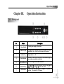
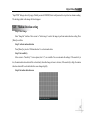
1
Thanks for purchasing our product PROSONIC Please read this manual carefully before using Statement: · We strive to ensure the exactness and integrality of the manual in the process of preparation, but still error or omission is inevitable. · The copy, transmission, plagiary, storage in retrieval system, or translation into any language without written authorization is prohibited. CHAPTER I. 1.1 ABOUT THE PRODUCT .................................................................................................................................... 5 INTRODUCTION ................................................................................................................................................................. 6 Digital Video Recorder 1.2 FUNCTIONS AND FEATURES ................................................................................................................................................ 6 CHAPTER II. 2.1 2.2 INSTALLATION INSTRUCTION.................................................................................................................... 10 CHECK THE DEVICE ......................................................................................................................................................... 10 INSTALL .......................................................................................................................................................................... 10 CHAPTER III. OPERATION INSTRUCTION.......................................................................................................................... 13 3.1 3.2 3.3 3.4 3.5 3.6 FRONT PANEL……………………………………………………………………………………………………………… .. 13 REMOTE CONTROLLER ................................................................................................................................................... 14 MOUSE OPERATION ......................................................................................................................................................... 15 MENU OPERATION ........................................................................................................................................................... 15 INPUT METHOD ................................................................................................................................................................ 17 SCREEN DISPLAY IN RUNNING STATE ................................................................................................................................ 17 CHAPTER IV. BASIC OPERATION......................................................................................................................................... 19 4.1 4.2 4.3 4.4 4.5 4.6 4.7 4.8 4.9 TURN ON ......................................................................................................................................................................... 19 DATE/TIME SETTING ........................................................................................................................................................ 19 RECORDING SETTING ...................................................................................................................................................... 20 SECRET RECORDING SETTING .......................................................................................................................................... 21 PLAY (PLAYBACK) ........................................................................................................................................................... 21 SINGLE FRAME PLAYING .................................................................................................................................................. 22 DUAL WORKFLOW OPERATION ........................................................................................................................................ 22 SEARCH AND PLAY ........................................................................................................................................................... 22 TURN OFF ........................................................................................................................................................................ 23 CHAPTER V. 5.1 2 MENU AND PARAMETER SETTINGS .......................................................................................................... 24 LOCAL DISPLAY ............................................................................................................................................................... 24 Digital Video Recorder 5.2 5.3 5.4 5.5 5.6 5.7 5.8 5.9 5.10 5.11 5.12 5.13 5.14 5.15 5.16 5.1.1 Password operation instruction ..................................................................................................................................... 25 IMAGE SETTING ............................................................................................................................................................... 26 5.2.1 Area mask setting ....................................................................................................................................................... 26 5.2.2 Image mask setting..................................................................................................................................................... 27 5.2.3 Alarm processing setting ............................................................................................................................................ 28 5.2.4 Video loss setting ........................................................................................................................................................ 30 5.2.5 Motion detection setting ............................................................................................................................................. 31 VIDEO RECORDING SETTING ............................................................................................................................................ 34 NETWORK SETTING ......................................................................................................................................................... 36 ALARM SETTING ............................................................................................................................................................. 38 ABNORMITY PROCESSING .............................................................................................................................................. 39 SERIAL PORT DEVICE ....................................................................................................................................................... 40 PREVIEW SETTING ......................................................................................................................................................... 47 USER MANAGEMENT ........................................................................................................................................................ 47 5.9.1 Authority setting ........................................................................................................................................................ 48 PLAY BACKUP .................................................................................................................................................................. 49 5.10.1 Playback by time search …………………… ……………………………………………………………………… 50 5.10.2 Backup ......................................................................................................................................................................... 50 TOOLS ............................................................................................................................................................................. 51 FACTORY SETTINGS ......................................................................................................................................................... 51 UPGRADE ........................................................................................................................................................................ 51 HDD MANAGEMENT ........................................................................................................................................................ 52 5.14.1 Recover data ................................................................................................................................................................ 53 5.14.2 HDD check (not available at present) ............................................................................................................................ 53 LOG MANAGEMENT ......................................................................................................................................................... 53 SYSTEM INFORMATION .................................................................................................................................................... 54 3 Digital Video Recorder CHAPTER VI. NETDVR OPERATION INSTRUCTION......................................................................................................... 55 6.1 6.2 6.3 6.4 FEATURES ....................................................................................................................................................................... 55 CONFIGURATION ............................................................................................................................................................. 56 START SOFTWARE ............................................................................................................................................................ 56 MAIN MENU ..................................................................................................................................................................... 57 6.4.1 Channel management ................................................................................................................................................ 58 6.4.2 User management....................................................................................................................................................... 60 6.4.3 Proxy management .................................................................................................................................................... 61 6.4.4 Channel number ........................................................................................................................................................ 62 6.4.5 Language .................................................................................................................................................................... 63 6.4.6 Change skin................................................................................................................................................................ 63 6.4.7 Local settings.............................................................................................................................................................. 63 6.4.8 Exit ............................................................................................................................................................................. 65 CHAPTER VII. 7.1 7.2 7.3 7.4 7.5 7.6 7.7 7.8 SPECIFIC OPERATION OF NETDVR ........................................................................................................ 66 RIGHT-CLICK MENU ........................................................................................................................................................ 66 VIEW ............................................................................................................................................................................... 66 PATROL ........................................................................................................................................................................... 67 TAKE PICTURE ................................................................................................................................................................. 68 RECORD VIDEO................................................................................................................................................................ 68 MONITOR AUDIO ............................................................................................................................................................. 68 ADJUST IMAGE QUALITY AND FRAME RATE ..................................................................................................................... 69 EXIT ................................................................................................................................................................................ 69 CHAPTER VIII. KEYS DEFINITION .................................................................................................................................... 70 CHAPTER VIIII. PAN/TILT CONTROL................................................................................................................................ 73 4 Digital Video Recorder 9.1 PAN/TILT CONTROL .......................................................................................................................................................... 73 9.2 NETWORK PAN/TILT CONTROL ........................................................................................................................................ 73 CHAPTER X. INTERNET EXPLORER SETTINGS ……………………………………………………………………...……. .75 10.1 INTERNET OPTIONS SETTINGS ON PC………………………………………………………………………………………….75 10.2 VIEW DVR IMAGE BY IE………………………………………………………………………..…………………..…….….….76 10.3 VIEW DVR FIELD IMAGE……………………………………………………………………………..…………………...…….79 10.4 ADJUST FRAME RATE…………………………………………………………………………………………………..……….79 10.5 PLAY/BACKUP VIDEO ON DVR…………………………………………………………………..……………………..……….80 10.6 CAPTURE VIDEO…………………………………………………………………………………………….…..……...……….82 10.7 PLAY THE CAPTURED/BACKUP VIDEO……………………………………………….………….…………….……………….82 10.8 LISTEN IN VOICE………………………………………………………………………………………………….…….……….82 10.9 CONTROL VIDEO STREAM……………………………………………………………………………………………..….……82 10.10 ACHIEVE CONTROL OVER PTZ…………………………………………………………………..…………….………..…….83 10.11 OPERATE REMOTE MENU…………………………………………………………………………………………...…..…….83 CHAPTER XI TROUBLESHOOTING ..................................................................................................................................... 84 APPENDIX 1 SPECIFICATIONS AND PARAMETERS .................................................................................................... 89 APPENDIX 2 PACKING LIST ……………………………………………………………………………….…………. 91 Chapter I. About the Product 5 Digital Video Recorder 1.1 Introduction Digital Video Recorder ( DVR ) is a digital monitoring product specially designed for security and surveillance. With professional embedded operating system PSOS, it is independent of the PC platform, aviod computer virus attack and eliminates halt permanently, which enables the system to run faster and more stably. DVR is also integrated with the feature of digital A/V server and can be connected to Internet to build powerful safety monitoring network. It can be widely applied in different industries, e.g. marketplace, office building, factory, warehouse, community, etc, ensuring a good security guarantee for them. Connection diagram: 1.2 Functions and features System mode With professional operating system PSOS, DVR is independent of the PC platform, eliminates halt permanently, so it is more stable and free of delay; Independent modular design makes the system more stable; 6 aviod computer virus attack and Digital Video Recorder Compression method Compress/decompress in H264 algorithm and higher definition is ensured; The audio is compressed in G.729 algorithm, which will bring better audio effect; Synchronized A/V compression; CBR and VBR compression; Display 4-channel A/V input, BNC output; 25 F/S (PAL) or 30 F/S (NTSC) real-time compression in each channel without delay; The contrast, brightness and saturation of field on live and playback image are adjustable; Customize the name of every image; Video recording 4-channel synchronized A/V recording; High definition image (CIF); CBR/VBR settings; Synchronized A/V recording; the parameters of video recording of each channel can be is adjustable (0.1F/S – 25 F/S); Manual, schedule, alarm and motion detection recording; Five levels are available for image quality and bit rate may be customized; set separately; frame rate Motion detection function 48 motion detection areas can be set in each image; Level 1-7 sensitivity can be set in each image; Storage Support up to 2 SATA hard disks (The capacity can support to1.5T) ; No limitation on capacity and rotation speed of hard disk; Manual overwriting, automatic overwriting and no overwriting are optional; Customize auto alarm of left capacity, i.e. alarm automatically when the left space of hard disk is less than the value 7 Digital Video Recorder you have set; The system is integrated with sleep function to reduce heat radiation of the recorder and extend the service life of hard disk; Search Search by date/time, list or exact search; Common/alarm video recording searching; Log function; Playback Synchronized playback of single channel A/V; Play: Fast forward, fast rewind, pause, single frame, previous track, next track, track head, track end, mute; Fast forward: 1/2×, 2×, 4×, 8×, 16×, 32×; Fast rewind: 1×, 2×, 4×, 8×, 16×, 32×; Version Device type, version number, version date; Capacity, video recording information (common/alarm), recording time; Working disk, cover mode and times; Card number appending (optional) According to the interface protocol provided by user, intercept the card number through RS232 or network port and append the information of card holder to corresponding image; PTZ control Support multi-protocol decoder with RS485 bus; Centralized control Control with keyboard through RS485 interface and one keyboard may control several devices separately according to ID; Alarm function 4 alarm inputs/1 alarm outputs; 8 Digital Video Recorder Customize time of alarm output; Customize alarm input type NC/NO; Clear alarm manually or by remote control/network; Open/Close buzzer in menu; Camera blank or video loss alarm; Support pre-alarm recording Network function Support 10/100MB self-adaptive network; Download backup with network control software; Control PTZ/lens, speed dome camera with network control software; Support WEB browsing; Multiple Viewers Support multiple viewers simultaneously by IE browsing Safety protection 128-byte data encryption; Dual password protection: administrator and operator; Power switch and panel lock; the front panel will be locked automatically within a certain period; Backup Backup in network or another PC; Backup with USB, DVDRW or USB HDD; 9 Digital Video Recorder Chapter II. Installation Instruction 2.1 Check the device Before install the digital video recorder, please check whether the appearance of the device is damaged and whether the accessories are complete. Then, open the case, remove the protective film and begin to install the device. Prepare the devices (camera, power supply and monitor, etc) which will be connected to the digital video recorder and connect them. 2.2 Install Important: Select appropriate installation position to provide good ventilation and prevent overheating of the device. Do not install the device near heat sources like radiator and ventiduct, or places with direct sunshine irradiation, too much dust, or mechanical vibration or impact. This digital video recorder isn’t equipped with hard disk. You may use the device without hard disk but you can’t record the video. High speed hard disk of 7200 rpm or higher is recommended. Install hard disk: get a cross screwdriver first. Step 1: Open the case. Step 2: Remove hard disk holder. Using a SATA cord to connect HDD onto SATA connector. It support capacity up to 2000GB. 10 Step 3: Put the hard disk into the holder and fix it with screws on both left and right. Step 4: Put the holder back to the device and fix it with screws. Digital Video Recorder Step 5: Connect SATA hard disk data cable. To connect two hard disks with one data cable, you need to set the master drive and slave drive. The data cable has three joints, which will be connected to the pin sockets on motherboard, master drive and slave drive respectively. Level the data cable joints and the pins of sockets when connect. Step 6: Connect the power cord of hard disk. Step 7: Put on the cover of the case and fix it with screws. When hard disk is installed, connect other parts to the interfaces on rear panel. Rear panel 1. Audio input Connect to (analog) Audio input device. 2. Audio output Connect to (analog) audio output device. 3. Video input Connect to video input device. 4. Video output 11 Digital Video Recorder Connect to monitor and output video signals. 5. UTP network port Connect to Ethernet devices, e.g. Ethernet switch, Ethernet hub, etc. 6. Power supply Connect to DC12V/3A power supply. 7~9. Connection terminal of alarm input/output signal and RS485 signal Connect to peripheral equipment like alarm, decoder, pan/tilt, etc. 10. Fan It is used to keep ventilation in side the case. It cannot be blocked by any articles. 12 Digital Video Recorder Chapter III. 3.1 Operation Instruction Front panel No Name 1 Power Switch 2 Indicator Light 3 Number Key 4 State Indicator 5 Infrared Receiver 6 Menu Key and Direction Key 7 USB Interface Description Control power supply to the device. The light of power indicator will be on after turn on the power and blink 1 cyle/s. It will be off after turn off the power. Input number 1 ~ 10 Indicate the work state of the device. The correlative light will be on when on correlative work state. Receive the signal from remote controller Press【Menu】key to enter operation. Then press up【↑】down 【↓】left【←】right【→】to move the cursor. Connect the USB and CDRW to update the system and backup. Or operate the USB mouse 13 Digital Video Recorder 3.2 14 Remote controller S/N Name 1 Power 2 Advance 3 Playing Same as Alert, Cancel, Search, PTZ control, Exit, Info and VGA on front panel Same as Play, FF and FR on front panel 4 Record Same as Record on front panel; start/stop video recording 5 PTZ control Control pan/tilt 6 Main menu Same as Direction and Menu keys on front panel 7 Numerical keys Same as numerical keys on front panel 8 Channel switch Press to display images in different number of channels Remark Same as [Power] key on front panel; turn on/off the power Digital Video Recorder 3.3 Mouse operation Connect the mouse to the USB interface in front panel. Left click to confirm selection and right click to select menu. Right click menu is shown as below: 3.4 S/N Name Remark 1 Set parameters of recorder Same as Menu key 2 Recording data Same as Search key 3 System information Same as Information key on front panel 4 Alert (disalert) Same as Alert key on front panel 5 Timing (Cancel) Enable/disable timing 6 Cancel alarm Same as Cancel key on front panel 7 PTZ control Same as PTZ control key on front panel 8 Playback Same as Play key on front panel 9 Record (Stop) Same as Record key on front panel Menu operation To enter “System settings” menu, press [Menu] key on front panel to enter directly if password protection is disabled. If password protection is enabled, “Input PSW” window will popup. For example: 15 Digital Video Recorder Note: Password protection is divided into two levels: administrator (senior user) and operator (common user). (See Chapter 5.9.1: Authority setting on P.29.) Prompt: Default password of administrator is 88888888; default password of operator is 66666666. If password protection is enabled, press [Menu] key and enter valid administrator password in the dialogue box "Input PSW", then, “System settings” menu will popup. Enter operator password and the operator interface will popup. The icons of the functions that operator has authority is in white. If the operator doesn’t have the authority, the icons will be in gray. If the password protection is disabled, you can press [Menu] key to enter “System settings” menu directly. In System settings menu, press [↑], [↓], [←], [→] key to move cursor and press [Menu] key to confirm selection. Press [↑], 16 Digital Video Recorder [↓], [←], [→] key to select items in main menu and press [Menu] key to enter the submenu and set the parameters. In the submenu, the operation will be canceled if you press “Cancel” button. Press “OK” and the setting will be saved. Return to main menu and move cursor to “Exit”, then, press [Menu] key and the following message box will popup: To save the setting, click “Yes”. Click “No” to exit without saving. To continue the setting, click “Back”. 3.5 Input method In menu operation interface, enter text edit box (e.g. “Name” box in “Image setting”) and input method will be displayed in status bar at the bottom of the screen, as shown below: Press [Menu] key on front panel to switch input method. For example, to input numbers, switch the input method to “123” and then press 0-9. To change input method, press [Menu] key. Available input methods include: capitalized letter, small letter, number and location (see “Location input method” in appendix). To input letters, press numerical keys 1-9. Press a key consecutively to switch letters. After input the letter, wait for 2 seconds to input next letter. 3.6 Screen display in running state Press [Display] key on front panel consecutively and different symbols will be displayed on the screen. Video recording symbol: The blue round icon indicates manual recording state. 17 Digital Video Recorder Video recording symbol: The yellow round icon indicates timing recording state. Video recording symbol: The red round icon indicates alarm recording state. Playing symbol: Indicates the recording is being played. FF symbol: Indicates fast forward. FR symbol: Indicates fast rewind. Single frame symbol: Indicates pause in single frame playing state. Timing symbol: Indicates the video recorder is in timing state. Alert symbol: Indicates the video recorder is in alerted state. If alarm signals generated, the recorder will record and output the alarm automatically. When alarm occurs, the symbol will turn into solid from hollow. **/**/** Time display: Display the playing time or recording time. Image quality symbol: One yellow strip and two white strips indicate low quality; three green strips indicate medium quality; two green strips and one white strip indicate high quality; one green strip and two white strips indicate highest quality; two red strips and one white strip indicate custom. (The quality of Custom is highest by default) Hard disk status: 18 Digital Video Recorder Chapter IIII. 4.1 Basic Operation Turn on Check whether the current and voltage of power supply accord with the digital video recorder before turning it on. Check whether video recording device is connected and whether the connection is proper. Check whether monitor is connected to VOUT port or VGA port on rear panel. Connect properly and then turn on the recorder. Press Power button on front panel to turn on the recorder. Note: If “No hard disk. Continue?” is displayed when you turn on the recorder; it indicates that the hard disk hasn’t been installed. Please check whether the hard disk is connected properly, or whether is damaged. If the recording scene isn’t displayed on the screen, please check the connection of video input device. Note: If the hard disk has been used and “Hard disk hasn’t been formatted. Format now?” is displayed; click “Yes” to format the hard disk and then you can record video normally. Click “No”, the hard disk won’t be formatted and you can’t record video normally. 4.2 Date/time setting You need to set date/time before record video. Prompt: Stop the video recording when set date/time. If it is in recording state, the status bar will indicate the state and the settings won’t take effect. Step 1 Press [Menu] key to enter system menu. If password protection is enabled, the “Input PSW” window will popup when you press [Menu] key and you need to enter valid password. (Default password: 88888888) If password protection is disabled, you can press [Menu] key to enter menu setting interface directly. Step 2 Press [↑], [↓], [←], and [→] to move cursor. Select “BaseSet ” to enter the menu and then select “Date/time 19 Digital Video Recorder setting”, as shown below. Time Zone Move cursor to “Time Zone” and press [Menu] key to select “Summer” or “Winter”. Press [←]/[→] to select an option and press [Menu] to confirm. Date Format Move cursor to “Time Zone” and press [Menu] key to select “Y-M-D” or “M-D-Y”. Press [←]/[→] to select an option and press [Menu] to confirm. Date/time Setting Move cursor to the item and press numerical keys on front panel to enter the values. Step 3 Select “OK” and press [Menu] to save and exit. 4.3 Recording setting Step 1 20 Press [Menu] key to enter system menu. Press [↑], [↓], [←], and [→] to move cursor to “RecordSet”. Digital Video Recorder Step 2 Customize quality in “Quality” box. Move cursor to Quality and press [Menu] key to enter. Available options include: Highest, High, Medium, Low and Customized. (Higher quality will occupy more space.) Press [←]/[→] to move cursor to desired option and press “OK” to save and exit. (Do not change this setting if not necessary) Step 3 The “Audio” option in audio options should correspond to video of each channel. Move cursor to Audio and press [Menu] key to enter. If “Image 1” is selected in channels, you need to select option “1” or “2” in audio options and then the audio and video will be recorded synchronously. Select “No” and the audio won't be recorded. Step 4 After setting, click “OK” to save and exit, or click “Cancel” to exit without saving. Step 5 When system setting is finished, press [●] button on front panel and a dialogue will popup for you to select channel. Click “Select all” to select all options. Click “Deselect all” to deselect all options. After selection, click “OK” to save and exit. Only the video of selected channel will be recorded. The recording state will be displayed in lower left corner. The green icon “●” indicates manual recording. To stop recording, press [●] button on front panel. In recording state, click numerical key (1-16) to switch to the channel and preview in single image. 4.4 Note: Video recording can’t be executed in the system setting process. Secret recording setting “Secret recording” may be enabled in the process of common video recording. To enable secret recording, click [Menu] – “Video recording setting” – “Secret recording”. The scene won't be displayed in secret recording process. You also can’t play the recording during this process. 4.5 Play (playback) In recording state, press [] key to play the recording directly. In playing state, the “” icon will be displayed on VFD and monitor. Press [] key again to stop playing. The recording is played in single image; press numerical key 1-16 to switch channel. (Key 1-16 corresponds to image 1-16.) Note: The last recording, no matter it is common recording or alarm recording, will be played automatically. You can perform the following operations when play recording. 21 Digital Video Recorder Press button to play fast reversely. Press button to play fast forwardly. Press | button to play next track. Press | button to play previous track. Press Play button to resume normal playing and press it again to stop playback. 4.6 Single frame playing In the playing process, press [] button on front panel to pause the recording. Press [] button again and the playing will be paused and enter single frame playing state. The recording will be played by single frame when you press the button consecutively. Press [] button again to resume normal playing. 4.7 Dual workflow operation Dual workflow operation indicates that the playing and recording will be performed at the same time. Recording and playing are two independent workflows. In monitoring state, you can perform either recording or playing; In dual workflow operation process, the recording is always in background and the playing is always in foreground. If recording is performed in playing process, no response will be displayed on the screen, but the recording indicator on front panel will be lit. If the playing is stopped, the recording in background will appear on the screen. If the playing is performed in recording process, the image being played will be displayed on the screen and the recording image will go to background. Prompt: If it is not necessary, avoid dual workflow operation. It will shorten the service life of hard disk if searching and playing are performed continually for long time. 4.8 Search and play Step 1: Press [Search] button on front panel to enter searching menu setting. The following image will be displayed: 22 Digital Video Recorder Step 2: Select file type of recording to search. Common recording and alarm recording are available. Click [↑]/[↓] key to select recording. Click [←]/[→] key to select page. Press [Menu] key to select the recording (or multiple options) to play. The grounding of the item where cursor locates is yellow and the selected item is green. Step 3: Click [↓] key to move cursor to “Play” button to play the selected recording. Click “Backup” button to backup the recording. 4.9 Note: To backup, stop the video recording first. The playing and backup will take effect only when recording is selected (with green grounding). The channel selection dialogue box will popup; select a channel and the recording data of this channel will be backup. The channels that haven’t been selected won’t be backup. External device is necessary for backup. Turn off Press the Power key on front panel to turn off the recorder. Note: If the recorder is in alarm or alert state, please press Alarm key or Alert key to restore common recording first, and then press [●] to stop recording or press [] to stop playing. The recorder shouldn’t be turned off in backup process; otherwise the backup recording will be lost. Prompt: Cut off the power supply of recorder first and then turn off the peripheral devices. If you won’t use the recorder for a long time, remove the power cord from outlet. 23 Digital Video Recorder Chapter V 5.1 Menu and Parameter Settings Local display Output system PAL and NTSC are available. The system should be same to that of the output device. It is PAL in Mainland China. Language Select menu language. Simplified Chinese, traditional Chinese, English, Hungarian, Spanish are available. Brightness Adjust the brightness. Transparency Adjust the transparency of menu. Device NO. Assign number to every recorder for the convenience of operation. If the keyboard is connected to multiple recorders, assign number to every recorder to make it convenient to identify and operate the recorders. Press numerical keys to customize device NO. 24 Digital Video Recorder Password operation Press [Menu] key to select. If password protection is enabled, you can enter the password and then customize the menu. If password protection is disabled, press Menu key to enter menu setting interface directly. Panel lock Lock front panel. To lock the panel, press [Menu] key to select the tag in options. (The maximum waiting time is 99 minutes before panel is locked.) You can’t operate the panel if it is locked. “Wait” indicates the time before panel is locked. The panel will wait for this period of time before it is locked. Press numerical keys to enter time. Activate log Activate log. To activate log, press [Menu] key to select the tag in options. Note: There is no log if it is deactivated. VGA resolution Adjust the resolution of VGA display which is connected to the recorder. Available options: 600×800, 1024×768, 1280×960. Higher resolution will provide more clear image. The modification of image resolution will take effect after the recorder is restarted. If there is no VGA display, please enter menu from BNC into local display to check whether the outpu setting is under VGA. If not, set it ifrst. Refer: 5.1 5.1.1 Password operation instruction Two modes are available to operate password: if password is activated, you need to enter valid password to perform operations like enter menu, cancel alerting and timing. If password is deactivated, you needn’t to enter password to perform operations. 5.2 Image setting 25 Digital Video Recorder Select image Name Select video recording image. You can select up to 16 images or select single image to operate. Give name to the recording image for the convenience of operation and viewing. You can name every image here. Press [Menu] key to switch input method if you need to input characters or numbers. Available input methods are: number, capitalized letter, small letter and location code. Position Set the position of the image name displayed on the screen. Available options are: A (bottom center), B (centering), C (lower left) and D (lower right). Brightness Customize the brightness. Contrast Customize the contrast. Tone Customize the tone. Saturation Customize the saturation. Privacy masking Shield the sensitive or private area in the monitoring image, e.g. the keypad in ATM monitoring. Area Set the position and size of shielded area. Mask alarm Customize mask alarm. If the lens is masked, it will record and output the alarm. Video loss Customize video loss. Activate “Video loss process” and the loss of video signals caused by video cable or camera fault will be detected in time. Motion detection Detect the moving object in monitoring state. Analyze the video image to check whether the video scene has been changed. If video scene is changed, confirm the processing mode in “Motion detection process”. Motion detection type Select video recording type. Common and alarm are available. Alarm motion detection will take effect in alerted state only and alarm recording is generated. Common detection recording doesn’t require alerting and produce common recording. 5.2.1 Area mask setting Step 1: Select image 26 Digital Video Recorder Move cursor to “Select image” to select the image to set mask. Press [Menu] to confirm. Step 2: Set mask area Enter mask setting interface. Press [Menu] key to select “Mask alarm” to activate Area button. Move cursor to “Area” and press [Menu] to enter mask area setting interface, as shown below: In mask area setting interface, red line is used as the direction line of area selection. Press the same direction to zoom in the area and press the opposite direction to zoom out the area. You can customize the settings. (One image can cover one area only) Press [Menu] o return to “Image setting” interface after setting. Note: Only two mask areas are supported at present. Step 3: Copy channel You may copy the contents of area mask setting to another channel or all channels. Select a channel in “Copy setting to” and click "Copy” button. Repeat step 1 and 2 if the areas of other channels are different. Step 4: Save After the area mask setting of all channels, click “OK” button in “Image setting” menu to save and exit. 5.2.2 Image mask setting 27 Digital Video Recorder Step 1: Select image Enter “ImageSet” menu. Move cursor to “Select image” to select the image to set mask alarm. Press [Menu] to confirm. Step 2: Activate mask alarm Press [Menu] key to select “Mask alarm” to activate mask alarm. Step 3: Sensitivity setting Set “Sensitivity”. Seven options (level 1-7) are available. You can customize the settings. Step 4: Process mask alarm Move cursor to “Process”. Press [Menu] key to customize the parameters of processing dialogue box. (See Chapter 5.2.3: Alarm processing setting on page 21.) Step 5: Copy channel You may copy the contents of area mask setting to another channel or all channels. Select a channel in “Copy setting to” and click "Copy” button. Repeat step 1 and 4 if the areas of other channels are different. Step 6: Save After the image mask setting of all channels, click “OK” button in “Image setting” menu to save and exit. Step 7: Activate/deactivate alert Activate Press [Alert] key on front panel to activate mask alarm recording. Alerting symbol will be displayed on the screen. If alarm occurs, the symbol will be displayed on the screen. The recorder will buzz. Press [Clear] on front panel to clear alarm output. Deactivate Press the [Alert] key on front panel and the dialogue box “Input PSW” will popup if password protection is enabled. (Default password: 88888888) Enter valid password to exit alerting state. Mask alarm recording will be stopped and alerting symbol will disappear. 28 Digital Video Recorder 5.2.3 Alarm processing setting Select triggering image Press [Menu] key to select among the 16 images. The selected image will record when alarm is triggered. Move cursor to select image and press [Menu] to activate channel image. Buzzer Press [Menu] to activate buzzer. The buzzer will send alert if alarm occurs when it is activated. Upload alarm Upload the alarm image to remote host. (Available when management host is connected.) The time of image upload depends on the time of alarm upload. Alarm output Select output channel of alarm. Recording time before alarm Set the time of recording before alarm is triggered. Press numerical keys to enter time. The images before alarm will be saved as alarm recording according to preset time. If “Recording time before alarm” is “0”, the system won’t enter pre-alarm state, i.e. the period before alarm won’t be recorded. Recording time after alarm Set the time of recording after alarm is triggered. Press numerical keys to enter time. The alarm recording after alarm is triggered is saved. 29 Digital Video Recorder Alarm output time Output time of alarm signals. Alarm should be connected to the recorder. Note: You also need to set these three items (Recording time before alarm, recording time after alarm, alarm output time) in other options (e.g. video loss processing). Their values are interrelated, e.g. if the “Recording time before alarm” in “Mask alarm” is changed, the “Recording time before alarm” in “Video loss processing” will also change. 5.2.4 Video loss setting Step 1: Select image Enter “ImageSet” menu to select image to perform video loss setting. Move cursor to “Select image” to select the image to perform video loss setting. Press [Menu] to confirm. Step 2: Activate video loss Press [Menu] key to select “Video loss” option. Step 3: Video loss processing Move cursor to “Process” and press [Menu] key to enter. The interface of video loss processing is same to video mask interface. (See Chapter 5.2.3: Alarm processing setting on page 21.) Step 4: Copy setting You may copy the contents of area mask setting to another channel or all channels. Select a channel in “Copy setting to” and click "Copy” button. Repeat step 1 and 3 if the video loss processing modes of other channels are different. Step 5: Save After the video loss processing setting of all channels, click “OK” button in “Image setting” menu to save and exit. Step 6: Activate/deactivate alerting Activate Press [Alert] key on front panel to activate video loss alarm recording. Alerting symbol will be displayed on the screen. If alarm occurs, the symbol will be displayed on the screen and the recorder will buzz. Press [Clear] on front panel to clear alarm output and press [Alert] key again to exit alerting state. Deactivate 30 To stop video loss alarm recording, press [Alert] key on panel first. If password protection is enabled, the Digital Video Recorder “Input PSW” dialogue box will popup. (Default password: 88888888) Enter valid password to stop video loss alarm recording. The alerting symbol in the image will also disappear. 5.2.5 Motion detection setting Step 1: Select image Enter “ImageSet” interface. Move cursor to “Select image” to select the image to perform motion detection setting. Press [Menu] to confirm. Step 2: Activate motion detection Press [Menu] key to select “Motion detection” to activate mask alarm. Step 3: Set sensitivity Move cursor to “Sensitivity”. Seven options (level 1-7) are available. You can customize the settings. If the sensitivity is low, the motion detection alarm will be activated only when the change of scene is obvious; if the sensitivity is high, the motion detection alarm will be activated when the scene changes slightly. Step 4: Set motion detection area 31 Digital Video Recorder In the video scene of this channel, you need to define which area will be processed if motion detection occurs. The whole image is divided into 48 (6×8) panes. Three colors are available for cursor to set motion detection: yellow indicates moving cursor only; blue indicates setting motion detection area and the panes that blue cursor moves across will turn into red, indicating that these areas are selected; green indicates deleting motion detection area and the panes that green cursor moves across will turn into grey, indicating that these areas are not selected. Press [Menu] key o switch the color of cursor among yellow, blue and green. Press [↑], [↓], [←], and [→] to move cursor to select area. If the color changes at selected areas, motion detection will be triggered. If the color change at areas that are not selected, motion detection won’t be triggered. As shown in the figure below: motion detection will be triggered in area A (red) instead of area B (grey). After selection, press “0” to exit. Step 5: Process motion detection alarm Move cursor to “Process” button of motion detection and press [Menu] to enter “Motion detection processing” interface. The interface of motion detection processing is same to video mask interface. (See Chapter 5.2.3: Alarm processing setting on page 21.) Step 6: Select type The recording of motion detection will be saved as alarm/common recording. In common recording process: when the setting of time period takes effect, it will be activated immediately after exit the menu; if alerting is activated, common motion 32 Digital Video Recorder detection will be disabled. In alarm recording process, if buzzer is activated, the device will buzz. The time of alarm recording depends on recording time before and after alarm. Alarm recording will take effected only when alerted. Step 7: Timing motion detection Perform motion detection in preset time period. Enter next step directly if you don’t set this option. To set timing motion detection, customize the time in dialogue box of period detection. Select the time period first and then input the beginning time and end time. Click “OK” to save and exit. Timing detection only relates to common detection and won’t affect the effective time of alarm detection. Prompt: Enter valid time. The end time must be later than the beginning time; otherwise the period motion detection won’t take effect. Step 8: Copy setting You may copy the contents of area mask setting to another channel or all channels. Select a channel in “Copy setting to” and click "Copy” button. Repeat the setting if the video loss processing modes of other channels are different. The type and time of motion detection and contents of timing detection won’t be copied. As the effective range of this section is all channels. Step 9: Save setting After the setting of motion detection, click “OK” to save and exit, and return to “Image setting” interface. Click “Cancel” 33 Digital Video Recorder to give up the setting. Step 10: Activate/deactivate alerting Activate If alarm recording is enabled, you need to press [Alert] button on front panel to activate motion detection recording. Alerting symbol is displayed. If alarm occurs, the recorder will buzz. Press [Clear] on front panel to clear alarm output and press [Alert] button again to exit alerting state. Deactivate To stop motion detection alarm recording, press [Alert] key on panel first and the “Input PSW” dialogue box will popup. (Default password: 88888888) Enter valid password to stop motion detection recording. The alerting symbol in the image will also disappear. Prompt: If motion detection alarm recording is activated, manual recording will be disabled. Alarm motion detection recording will be saved in hard disk as alarm recording. Common motion detection recording will be saved in hard disk as common recording. 5.3 Video recording setting Select channel Image quality and Custom. 34 Select the image being monitored. Up to 16 images are available. Set the quality of images being monitored. Five options are available: Highest, High, Medium, Low Digital Video Recorder Prompt: Higher quality image will occupy more space. Frame rate one second. Audio The number of images that will be recorded in one second. E.g. 25f/s indicates recording 25 images in Whether audio will be recorded in monitoring state. Channels 1-16 are available. Secret recording In monitoring state, the video won’t be displayed on the monitor but it will be recorded. Copy setting to Copy the setting of channels. It will be convenient for users to customize image parameters. Select channel and click “Copy” to copy the setting. Timing recording Record video at specified time. Space full Select the processing mode when hard disk is full. Resolution Display the resolution of monitoring image. CIF and HD1 are available. Image quality Five levels are available for image quality of recording. You can customize the size of these five options here. Different quality levels cost different hard disk spaces. Press numerical keys on front panel to change. Default values are recommended: 150, 200, 250, and 300. 5.3.1 Timing video recording setting Step 1: Date/time setting 35 Digital Video Recorder The recorder is activated in specified time period only. Date Ten options are available. Beginning time The time to start recording. The recording will be started at specified time. The format is 24-hour. Press numerical keys on front panel to input time. End time The time to stop recording. The recording will be stopped at specified time. The format is 24-hour. Press numerical keys on front panel to input time. Step 2: Select channel Press [Menu] to enter channel selection dialogue box; move cursor and press [Menu] to activate desired channel. After selection, click “OK” to save and exit. Prompt: Select among the 8 time periods in timing recording interface. Step 3: Save setting After setting, click “OK” to save and exit. Step 4: Start/stop recording Start Press [Timing] button on front panel to start timing recording. The timing symbol will be displayed on the monitor and VFD display. Stop To stop timing recording, press [Timing] button on front panel first. If password protection is enabled, the “Input PSW” dialogue box will popup. (Default password: 88888888) Enter valid password to stop timing recording. The timing symbol in the image will also disappear. If password protection is disabled, press [Timing] button to stop timing recording directly. Prompt: Manual recording will be invalid in timing recording process. Timing recording will be saved in hard disk as alarm recording. 5.4 36 Network setting Digital Video Recorder Type Available modes to get IP: Auto and Static. DHCP protocol is used to get IP automatically. The LAN must have DHCP server, otherwise the recorder can’t get IP. IP address This IP address is unique. The recorder can’t detect whether there IP address conflict automatically. Please specify valid IP address. Mask Used to mark net segments of subnet. Gateway Communicate between different net segments. Gateway address needs to be set. DNS It is special domain name service software. The device will get a dynamic IP address when it accesses network in PPPOE protocol. If this IP address is bound to S/N and/or name of device, DNS server will analyze S/N and/or name of device to the IP address. Input the IP address of domain server in “DNS address”. Host address If host IP and port are configured for the computer that manages the recorder remotely, the digital video recorder will send the signals to remote alarm panel if alarm or abnormal events occur. (Install client software in alarm panel first.) Port If client software is installed in PC, you need to configure the port before access the recorder with PC. Configure video transmission and information transmission before view the video and information. You need to input the port to access the recorder in IE. WEB port must be same to IE port. 37 Digital Video Recorder PPPOE With PPPOE, you may connect the PC to remote access device with simple bridging access device. Enter account and password to transfer information through network. DDNS Dynamic domain name service. Map user's dynamic IP address to a static DNS. When user accesses network, the client will send the dynamic IP of host to the server application in server host. DNS is necessary in “DDNS setting” of this video recorder. Prompt: When you input password, it is visible for you to check and memorize. When the input is finished or cursor is moved away from the password box, it will turn into star symbols. 5.5 Alarm setting Customize external alarm setting in alarm setting menu. You may customize the linkage of each alarm setting and the validity of each alarm output port. Alarm in Select alarm input number which will be set. Alarm input type Select N/O if the alarm input port is connected to normal opened alarm; select N/C if it is connected to normal closed alarm. 38 Digital Video Recorder Copy setting Process Copy the setting of this alarm output to another alarm input device. Set the processing when alarm is triggered. (See Chapter 5.2.3: Alarm processing setting on page 21.) Alarm out Select alarm output number which will be set. Alarm output type Select N/O if the alarm output port is connected to normal opened alarm; select N/C if it is connected to normal closed alarm. 5.6 Copy setting Copy the setting of this alarm output to another alarm input setting. Alerting delay Set the delay of alerting. Operator may leave the alerted area within this period of time. Abnormity processing Enter “Abnormity Processing” menu (refer to the picture above); there are two options: Hard Disk Full and Hard Disk Error, in each option, user can select Buzzer, Alarm Upload and Alarm Output for reminders. Note: Alarm Upload and Alarm Output are only available when alarming device is equipped; the Buzzer is built in the DVR host. 5.7 Serial port device 39 Digital Video Recorder Set the channel number of decoder, including velocity, data bit, stop bit, checkout and stream control, in serial port device menu. The values of these items must match the connected serial device. The default values are: 8 data bits, 1 stop bit, none checkout bit and hardware stream control. These data cannot be revised by customer. Serial port RS485 and RS232 are available. Bit rate Available options are: 19200, 9600, 4800, 2400 and 1200. The selected value must accord with the protocol and parameters of decoder. Device Central control keyboard (SX326, optional). The device is applicable when the option accords with the peripheral device of the recorder and parameters are correct. Prompt: The three items above are serial port device settings. The items below set the relationship between pan/tilt decoder and channel. Select channel Select channel. Decoder protocol Select the protocol type of decoder connected to this channel. Available options are: PANNSONIC, LLW, PELCO-D, PELCO-P, LILIN, NEON, PELCO-D YA, PELCO-D SFD, PELCO-P MK, PELCO-D ZT, PELCO-P ZT and ZHIMIN. 40 Digital Video Recorder Address ID Enter the address of the decoder connected to selected image and then you can switch the images and select the pan/tilt to operate. Step Control the rotation of lens. Bigger step indicates faster rotation of lens. Preset point setting Set and save the position, focus, aperture and zoom of the camera and mark the setting with a number. Copy Copy the decoder setting of this channel to another channel. Central control keyboard Available options are: L.C, PINERVE, SAMLINK and ZHIMIN. Prompt: Select central control keyboard protocol if central control keyboard is connected to serial port device. Add Card ID This function is mainly used in ATM. Activate this function, the account of every business on the ATM will be recorded (optional). 5.7.1 Auto Cruise The device has two serial ports, one is RS-232, usually used for connecting close range serial communication devices. Standard serial port, for example, is used for adding card ID, etc. The other one is RS-485 standard serial port, with various standard protocols built in. It can be used for speed dome camera, 485 decoder and centralized control keyboard, etc. 5.7.2 PTZ Lens and Adjusting Dome Camera Setting Serial port: select 485 serial port Bit rate: select one from 19200, 9600, 4800, 2400 or 1200, which should be consistent with the communication bit rate of the decoder or uniform speed dome camera. Note: the above parameters are for settings of all decoders, same parameters must be selected. Equipment: select decoder Channel selection: select the corresponding channel of the DVR controlled by the decoder, or it will lead to failure of control. 41 Digital Video Recorder Decoder protocol: select type of decoder protocol. The following decoder protocols are preset in the program, including “PANNSONIC”,“LLW”, “PELCO-D”, “PELCO-P”, “LILIN”, “NEON”, “PELCO-D YA”, “PELCO-D SFD”, “PELCO-P MK”, “PELCO-D ZT”, “PELCO-P ZT”, “ZHIMIN”. Note: different protocols can be used for different channels. Address ID: Input the address of the decoder connected to the selected screen. The address ID must be insistent with the address of the front-end decoder, or it will lead to failure of control. The address ID is set by user. Step length: Control the speed parameters when moving the PTZ. The bigger the step length is, the higher the speed will be. Preset points settings: This parameter is for setting of speed dome camera. The location of the camera, the focus, aperture and zoom should be preset and memorized, and a number should be used to mark the setting. Preset point number: input a number from 00 to 225. Adjust location: press the “Adjust” button to enter control status and adjust the location of the dome by direction buttons. Press Menu button to return. Save: to save current setting to the preset point number. Set your required preset points one by one. Load: input preset point number and press Load button, the dome will switch to the preset point automatically. If there is no preset point, the dome will remain still. 42 Digital Video Recorder Copy: to copy the set parameters of the channel to other channels to save time. Auto Cruise: auto cruise is to set the cruising path. The cruising path is a path on which the camera moves at a certain speed, passing through different cruising points with numbers. Each cruising point includes the preset point and time for stay. Cruising points: 16 (1 to 16) cruising points can be set at each channel, and each cruising point corresponds to a preset point. Preset points: set the preset point corresponding to the cruising point and make sure the preset point is defined. Cruising time: time of stay of the cruising point. Take channel 1 for example to introduce the operation method of the PTZ. For other channels, refer to channel 1: 1 To set the corresponding parameters of the PTZ in “Serial Device” menu and set the “Select Channel” ○ to “Screen 1”; 2 To set a series of preset points by “Set Preset Point”; ○ 43 Digital Video Recorder ○ 3 To set the “step length”, i.e. the moving speed from preset point to another; 4 Click “Auto Cruise” to set cruising path; ○ 5 Select “Cruising Point” and check “Enable cruising function of the screen” and “Enable this cruising ○ point”; 6 Input the preset point corresponding to the cruising point at the “Preset Point Number”; ○ 7 Input the stay time of the cruising point at the “Cruising Time”; ○ To set more cruising points, repeat step 5 to 7. Click OK to save the settings. Load auto cruise Under non-menu status, press the “PTZ” button at the front panel and input the channel number, and then press the “Auto” button, the PTZ will auto cruise each cruising point according to the settings in “Auto Cruise”. 5.7.3 PTZ Lens Control This device has a group of buttons to control PTZ lens, including: PTZ control, direction buttons, Iris+, Iris-, Zoom+, Zoom-, Focus+ and Focus-. When decoder or speed dome is correctly connected, the following method can be adopted to control the PTZ and lens. Please refer to below picture for different front panel: Prompt: 1. Power Switch 2.. Indicate Light 3. Numerical Key 4. State Indicator 5. Infrared Receiver 6. Menu key and Direction Key 7. USB Interface 44 Digital Video Recorder PTZ Lens Control Select PTZ lens control: press the PTZ control button, the PTZ icon will display at the lower left corner of the monitor, or the indicator will light to show that it is under PTZ control status. (PTZ status indicator in the gray blank) Direction buttons (Up, Down, Left and Right) control moving of the PTZ. FOCUS +: Record Video FOCUS -: Play Video IRIS +: Rewind IRIS -: Fast forward ZOOM +: Previous 45 Digital Video Recorder ZOOM -: Next Auto on: Alerting Auto off: Timing Supplementary 1 on: Search (for example wiper or heating, etc) Supplementary 1off: Information Supplementary 2 on: Quit Supplementary 2 off: Clear Note: Decoder control buttons of different types may correspond to different buttons on the front-panel. Speed dome camera and preset points control Select PTZ lens control Press PTZ control button and PTZ icon will display at lower left corner of monitor, then PTZ display symbol ( ) will appear at VFD display (not all types have VFD display, please refer to exact type of device) of the host panel, showing that it is under PTZ control status. User can press the number buttons on the panel to control the corresponding PTZ of the relevant channels (01 stands for the PTZ corresponding to control channel 1, and 02 stands for the PTZ corresponding to control channel 2). Press the [↑], [↓], [←] and [→] buttons to move the PTZ. Preset position of the dome Press the [Menu] button to enter system menu; select “Serial Device” and “Set Preset Point” in order and input a number standing for a preset point (from 00 to 63) in the “Preset Point Number” dialog box, and then select “Adjust” to adjust the dome into the position of the preset point by [↑], [↓], [←] and [→] buttons, and finally press the [Menu] button again and the system will save the preset 46 Digital Video Recorder point into the system. Load preset location of the dome Press the [Menu] button to enter system menu; select “Serial Device” and “Set Preset Point” in order and input the number of a preset point saved in the system (00 to 63) in the “Preset Point Number” dialog box and then select “Load” and press the [Menu] button again and the system will control the dome to move to the preset location. 5.8 Preview setting Enter “Preview Setting” menu as the above picture; firstly set the interval time of the preview, which is 5 seconds by default. User can set the time according to actual needs. The max time interval is 99 seconds. In the “Preview Rules”, Single Screen and Full Screen options are available. Then press the Ok button the preview will be enabled according to the set interval time. 5.9 User management 47 Digital Video Recorder Protect the setting and using of digital video recorder through authority setting. Set the management and operation authority in system settings. The levels of authority are: Administrator, Operator 1, 2 and 3. Administrator is enabled with the highest authority. The administrator may set the authority of operator. 5.9.1 Authority setting Step 1: Select operator Press [Menu] button to select user. Move cursor to select user. Press [Menu] button to confirm selection. E.g. select Operator 1. Step 2: Input password Press numerical keys to input old password. (Default: 66666666) Press numerical keys to input new password. The new password may be same to or different from old password. The password is 1-8 digits figure. Operator uses this password to access menus. Confirm new password 48 Repeat the new password to confirm. The prompt box “PSW checkout error” indicates that Digital Video Recorder you didn’t input same password. Authority setting Only selected authority may be set. Press [Menu] button to activate selected option. Step 3: Save setting Move cursor to select “OK” to save and exit. Note: If you access the menu with administrator, the “Input PSW” dialogue box will popup when you press [Menu] button. Input the administrator password and then set the menus. (Default password: 88888888) If you access the menu with operator, the “Input PSW” dialogue box will popup when you press [Menu] button. Input the password preset by administrator and then set the menus. (Prompt: Operator password must be different from administrator password.)In menus, the authorities appointed by administrator will display normal color and operator may customize. The authorities haven’t appointed by administrator will be in grey and valid. Administrator may change operator password and appoint operator’s authorities. Set and change administrator password and operator password in “Operation password setting” window. Old password is required to change password. Password protection may be disabled. Keep the “New PSW” and “Confirm PSW” box of administrator in “Operation password setting” window null and the password protection will be disabled. The operator password will be invalid if administrator password is canceled. Therefore, you can’t keep operator password without administrator password. You may keep administrator password only: keep the “New PSW” and “Confirm PSW” box of operator null; but the operator identity will be invalid. If administrator appoints complete authority to operator and allows the operator to set and operate all items, then, they will have different passwords and the operator may customize all “System settings” except “Operator authority setting”. The administrator is enabled with full authority by default and the authority setting of administrator is invalid. (e.g. cancel certain authority of administrator in menu.) 5.10 Play backup 49 Digital Video Recorder Input time Set the backup time. Backup will be performed in specified time period. Select channel Recording type Searching mode Select recording image. Only selected images will be backup. Select the type of video recording. Common, alarm and all are available. Set the accuracy of recording searching. Exact search will search the entire disk, but it has a lower speed. Quick search is bisearch, which ahs a higher speed. Input card number Backup device It is mainly used on ATM. You may also search according to card number. External devices: flash disk, USD hard disk or USB CD-R. 5.10.1 Search and play according to time Step 1: Select time Select the time to play or backup video recording. Press numerical keys to enter time. Step 2: Select channel Play or backup he video recording of selected channel. Press [Menu] to enter dialogue box. Press [Menu] button to activate single channel and press “OK” to confirm. Step 3: Select recording type 50 Digital Video Recorder Common, alarm and all are available. Select Common to operate common video recording. Select Alarm to operate alarm video recording. (Alarm video recording includes timing recording and detection recording.) Select All to operate all video recordings. Step 4: Select searching mode Quick search and exact search are available. Quick search isn’t accurate enough. If exact search is selected, all video recordings will be scanned. Step 5: Play Press “Play” button to play and press “Backup” button to backup. 5.10.2 Backup You can backup the contents in hard disk, network interface or CD-RW. To backup in USB device: connect the device to USB interface (in front panel) and then enter the recording backup option in menu, as shown in picture above. Select “USB device” in backup device option. Then, move cursor to “Backup” button and press [Menu] to backup. (Stop recording before backup.) When the prompt “Done” is displayed, you can remove the USB device. Note: Format the USB device in FAT or FAT32 format before using it for the first time. To backup in CD-RW: First, configure the CD-RW device as the slave drive of first IDE or master drive of second IDE; enter the recording backup option in menu, as shown in picture above; select “CD-RW” in backup device option and select backup mode, operation mode, time period and recording type; move cursor to “Backup” button and press [Menu] to backup. When the prompt “Done” is displayed, you can remove the disc. To backup in network, install client software first. 5.11 Tools 51 Digital Video Recorder 5.12 Factory settings Restore default settings. It will take effect when the device is restarted. (IP and gateway are also reset.) 5.13 Upgrade Upgrade the software. Check whether the language of original software is congruent with update. The update will fail if they don’t have same language. Select “Upgrade” and prompt box will popup. Two modes are available: If network interface is selected, you need to input the host IP of server application; then, select “Execute” to update. The process will be displayed in a message window. The special update software must be run on PC at specified IP. If USB is selected, make sure the USB device has been connected properly and the update application (upcmsdvr.bin) has 52 Digital Video Recorder been copied into root directory of USB device. And the file name must be upcmsdvr.bin Restart the recorder after update. Note: Do not interrupt the upgrading process. Cutting off power supply or pressing the power button is prohibited; otherwise, the recorder can’t be run in order. 5.14 HDD management Change the password of data saving. It will take effect after format. Press [Menu] button and the format dialogue box will popup. Password is needed. Note: All disks will be managed as a whole. You can’t manage a single disk separately. To manage a disk, open the case and remove other disks. Press numerical keys to input old password (default: 88888888). Input new password. The password contains figures only. The new password may be same to old password. Repeat the new password. The system will prompt if you didn’t input same 53 Digital Video Recorder new password. When password is confirmed, click “Back” to cancel format; or click “Execute” to format. When the hard disk is formatted, all files will be deleted. You need to input valid password to format the hard disk. 5.14.1 Recover data Click “Recover data” to restore the data in hard disk. Input the password (default: 88888888). Click “Back” to cancel the operation; or click “Execute” to restore the data. 5.14.2 HDD check (not available at present) 5.15 Log management View the log recorded in the digital video recorder. All operations will be recorded in log. Run Log management to view all operations of the video recorder. 5.16 System information Run System information to view the information of the video recorder, as shown in the picture below: 54 Digital Video Recorder Chapter VI NETDVR Operation Instruction Netdvr is the new generation network video monitoring software developed by us. It is integrated with powerful channel management function. You can monitor the audio/video through network. It supports network searching and playing, network backup and TCP/Multicast protocol, and may build perfect monitor center system with Managecenter. 6.1 Features Powerful multi-channel management function: support single channel and 4/9/16/25/36/49 channels; the operations between different channels are independent; Each channel may be customized separately and the number of IP addresses for each channel is unlimited (i.e. the number of video recorders is unlimited); you may also switch the channel of recorder (IP); Define the video recorders of certain channel; after setting, user may poll all video recorders of this channel manually or automatically; Multi languages (English, simplified Chinese, traditional Chinese) and skins (7 options available); Internet proxy management; Support Multicast function and up to 20 users may access a same video recorder; (Note: WAN Multicast function is invalid if you monitor the scene in WAN and the multicast function of router is disabled.) Perfect user management function and multilevel account authority management function: ADMIN is the super management account and defines the authorities of GUEST; perfect log management function; Convenient network list searching function: you can play or backup the common recording and alarm recording data with list and input a time period to search for recording data; Support network control of pan/tilt; Two modes are available to realize full screen in multi-channel monitoring: double click the window of monitored 55 Digital Video Recorder channel; click multi-image full screen in monitoring menu. In multi-image full screen, you click a window to display it in full screen; Support synchronized local A/V recording and shooting (support pause shooting); circle playing and progress bar playing of local recordings. 6.2 Configuration Operating system Simplified Chinese version: Simplified Chinese Windows 98/2000/ME/XP/2003/vista; Traditional Chinese version: Traditional Chinese Windows 98/2000/ME/XP/2003/vista; English version: English Windows 98/2000/ME/XP/2003/vista. Hardware CPU: P4 2.0 or higher; Memory: 512MB or more; Graphics memory: 64MB; LAN card: 10/100/1000MB Bandwidth 4-channel – ≥2MB; 9-channel – ≥5MB; 16-channel – ≥8MB; 25-channel – connect client and video recorder with 100MB network device. Install DirectX9.0 or above to get better playing quality. 6.3 Start software Click the Netdvr.exe on desktop to launch the software. The following dialogue box will popup: 56 Digital Video Recorder This dialogue box will initialize Administrator account. Please input and repeat the administrator password and then click “OK”. The system is in English interface by default when you use the software for the first time. 6.4 Main menu When the account is initialized, enter the main interface as shown in the picture below: The interface is in English by default. Select “Language” and “Skin change” to customize the language and skin. 57 Digital Video Recorder Note: The software is in single channel when it is initialized, however, you may select multi channels. 6.4.1 Channel management After the settings of language and skin, enter “Channel management” to input IP address of video recorder and customize the parameters, as shown below: Note: You need to input “Name”, “IP” and “Password”; the password here is for hard disk (the password used to format hard disk, instead of administrator password). Name: The video recorder that user has added. IP: IP or domain of current video recorder in LAN/WAN. Description: Description of user. Password: The password used to format the hard disk (default: 88888888). You can’t watch the video if password is invalid. Proxy: You need to set this item if you access the video recorder through proxy. It relates to the setting of “Proxy management” and you may select a proxy server in “Proxy management”. 58 Digital Video Recorder Patrol: If two or more video recorders are added in this channel, you need to select this option to patrol the recorders in this channel in poll mode. Default DVR: The recorder that user added to this channel. If this option is selected, the DVR will be connected directly when you view the scene. Add DVR: Enter the three items and click “Add”, and the DVR and information will be displayed on the left, as shown below: The status bar on the left displays the three added video recorders and their parameters. All the three added recorders are set as default DVR. When you view the scene, the software will connect to the first DVR in the list directly, e.g. “226” in the picture above. Modify DVR: Modify the parameters of added DVR. Select a DVR in status bar and click “Clear” button, then, input the parameters and click “Modify”. Delete DVR: Select a DVR in status bar click “Delete”. Channel name: Customize the channel name, as shown in picture above. 59 Digital Video Recorder Default mode: Monitor and Patrol are available. Patrol time: 5 sec by default. Move to: In multi-channel control, you can move any DVR from one channel to another. 6.4.2 User management User management includes three items: Account, Authority and Log. Account management: Administrator account features: set the authority; create and delete guest account; change administrator password and type of other accounts, as shown in the picture below: You need to input Name, Password and Verify password. Then, click “Add” and the name and description of added account will be displayed in the status bar on the left, as shown below: 60 Digital Video Recorder Authority management: When zslc is added as guest account, click this option to appoint the authorities of zslc. Select “zslc” in “Select user” drop menu and then select the authorities. In the picture above, select “Channel 1”, “Language”, “Change skin” and “Play”, then, click “Authorize” button and zslc account will be enabled with the following authorities: all playing authorities in “Channel 1” and “Language” and “Change skin” in main menu. For other operations, a warning window will popup: No authority. Log management (not available at present) 6.4.3 Proxy management To use this function, another proxy software is needed. If this function is enabled, it will connect to the IP of proxy server instead of DVR when you view the scene. When proxy server is started, up to 20 users may access a same proxy server to view the video scene. 61 Digital Video Recorder Name: Name of proxy server; IP: The IP address of PC that proxy software runs on; Proxy user: User name of proxy software; User password: User password of proxy software; Verify password: Enter same password as “User password”; Description: Description of proxy server. As shown in the picture above, the proxy software is launched on PC with IP address as 192.168.1.1 and the user name is xing. 6.4.4 Channel number Channel number item is controlled through multi-channel. Take 9 channels as an example: If user selects 9-channel centralized control, the Netdvr software will be displayed in 9 channels (9 video windows). Then, enter “Channel management” to add DVR and customize the each channel, as shown in the picture below: 62 Digital Video Recorder Different from single channel, you need to customize Channel 0, Channel 1, Channel 2…Channel 8 separately. Note: The number of DVR in each channel is unlimited. After setting, the operation of each channel is independent. 6.4.5 Language Three languages are available: Simplified Chinese, Traditional Chinese and English (default). 6.4.6 Change skin Seven options are available. 6.4.7 Local settings Local setting is necessary. It relates to the image quality and storage path of backup files, etc. 63 Digital Video Recorder Storage path: The storage path of backup files and recording files. You can use default path (select “Default path”) or customize the path. You can select o overwrite the backup or recording files or not. If the size of recording file is too big, you can split the file into different segments. Input the size (unit: MB) of segment. You can select one segment to play or play all the segments in sequence. Image resolution: Modify this parameter to play video streams of different resolutions. The system will recognize the resolution automatically. Image quality: Set the quality of image. Higher quality will cost more system resource. (Select lower quality to get better PC performance.) Window color: Select the colors of background, separator of separate window, separator of selected window and time. If the image is in light color, select black for time. The time is displayed in gray color only. The colors in the picture above are default. Select channel: If only one channel is selected, only the data of channel 1 will be sent when you view the scene and play 64 Digital Video Recorder recording files; if multiple channels are selected, the data of all selected channels will be sent. The system will send the data of all channels by default. The setting will take effect after reconnection. Add DVR ID: Select “Yes” to add the channel number of DVR on the image. (Default: No) View mode: Common and Multicast are available. Their difference is: only one user may view the DVR if Common is selected, while multiple users may view the DVR at the same time if Multicast is selected. If there is a user viewing the image in multicast mode, all users will access the DVR in multicast mode. Up to 20 users may view the images in multicast mode at the same time. Default mode is “Common”. The setting will take effect after reconnection. Image zooming: Customize this parameter to zoom the image. When you view the scene or play recording files, hold the “Ctrl” key and double right click on the image. Set overtime: This function is for special users. All operations of the system will be stopped automatically if the mouse isn’t moved within this period of time. Input 0 to disable this function. Set delay time: Set network delay to keep the continuity of images. For example: if the delay time is 5 seconds, the data sending will be delayed for 5 seconds after reading, so that there will be enough images in buffer area, but the images at the network end will be 5 seconds later than the scene. Input 0 if you have high requirement on real time. Command port: (Default: 3357) You can change the port to adapt to the setting of firewall or router. Make sure the port is same to the setting of the DVR you will access. Data port: (Default: 3358) You can change the port to adapt to the setting of firewall or router. Make sure the port is same to the setting of the DVR you will access. Talk port: (Default: 3360) You can change the port to adapt to the setting of firewall or router. Make sure the port is same to the setting of the DVR you will access. 6.4.8 Exit Exit the software. 65 Digital Video Recorder Chapter VII 7.1 Specific Operation of NETDVR Right-click menu Move cursor to display area and right click, and the menu as shown below will popup: 7.2 View Click “View” and the following two modes are available to connect: 1. If you have customized “Default DVR” in “Channel management”, it will connect to the IP of default DVR and display the scene video; 2. If you haven’t customized “Default DVR”, the following dialogue box will popup: Select a DVR and click “OK” to view the scene. 66 Digital Video Recorder To select default DVR in this interface: Select a DVR and “Default DVR”. When you are viewing the scene, you can zoom or switch the video windows, take pictures, record video and control PTZ. 7.3 Patrol If you added multiple DVR to a channel and select “Yes” in “Patrol”, you need to input time in “Patrol time” (default: 5 sec). 67 Digital Video Recorder As shown in the picture above, select “Yes” for DVR 227 and 228 in Channel 0 and set the “Patrol time” as 5 sec. After setting, right click in channel 0 and select “Patrol”, then, the software will connect to the IP of DVR 227 and 228 in channel 0 in sequence and patrol the images of each DVR according to the preset time. Patrol DVR 227 in the first 5 seconds and patrol DVR 228 in the second 5 seconds, then patrol DVR 227 in the third 5 seconds, and so on. 7.4 Take picture Click “Take picture” button to take the picture of a single frame image. The naming rule of pictures is: time.bmp. The pictures are saved in C:\Program Files\DVR software\DVR player\CapFiles. You can open them in picture editing tools. 7.5 Record video Click “Record” button to start recording and click “Stop” button to stop the recording. The files are saved in C:\Program Files\DVR software\DVR player\RecFiles. The naming rule of video recording files is: 4r+time.mpg. 7.6 Monitor audio Click “Monitor audio” button and you can monitor the audio of the scene at the same time. Click “Mute” to cancel audio monitoring. (In multi-channel control, you can monitor one channel only; otherwise the audio will be mixed.) 68 Digital Video Recorder 7.7 Adjust image quality and frame rate Change the image quality and frame rate of front DVR. As shown in the picture below: Image quality: Four options are available (Level 1-3, Custom). If Level 1-3 is selected, you can only change the frame rate. Customize bit stream: If Custom is selected in Image quality, you can input the size of bit stream (unit: MB). Frame rate: Input valid number (1-30). The parameters here are effective to current video stream and won’t be saved. For example, select Level 2 in Image quality and 25F/S in Frame rate. When you view the scene, change the frame rate into 12.5F/S, then, the frame rates of scene and the recording files of DVR are both 12.5F/S. Stop viewing or recording, then, perform the operation again, and the frame rate will turn into 25F/S. 7.8 Exit Click “Exit”. 69 Digital Video Recorder Chapter VIII Keys Definition You can press the following keys when you view the scene, play local files or operate the DVR. Stop: Press this key to cancel the monitoring. Pause: When you play local files, operate DVR files (list playing) or operate local DVR HDD, you can press this key hold the playing and press “Play” to resume the playing. Play: Press this key to play the recording files. When play the recording files, you can zoom in/out the window, take pictures, record video, play fast, pause or play in single frame. Fast/slow playing: Press this key to realize fast/slow playing. You can check the current playing state in the information bar in upper right corner of the interface. Press this key for the first time to play in 1/8 speed; Press this key for the second time to play in 1/4 speed; Press this key for the third time to play in 1/2 speed; Press this key for the fourth time to play in 2 times speed; Press this key for the fifth time to play in 4 times speed; Press this key for the sixth time to play in 32 times speed; Press this key for the seventh time to skip frames; Press this key for the eighth time to play in 1/8 speed; and so on. Single frame: In playing or pause state, press this key to play in single frame. Repeat: Press this key to play the recording file repeatedly. 70 Digital Video Recorder Record video: Press this key to start the recording and press “Stop” to stop the recording. The files are saved in C:\Program Files\DVR software\DVR player\RecFiles. Take picture: Press this key to take the picture of a single frame. (support pause & shooting) Audio: It has same function with “Monitor audio”. Press this key to enable audio and press “Mute” to disable audio. The audio of first channel is played by default when audio is enabled. You may press “Audio channel selection” key to realize this function, as shown in the picture below: The corresponding audio channels are: 1.2.3.4. 9.10.11.12. 5.6.7.8. 13.14.15.16. When audio is enabled, select “Channel 1” to play the audio of channel 1; select “Channel 2” to play the audio of channel 2; and so on. Talk: Press this key to realize talk function. The network end and front DVR scene may talk to each other. Press “Stop” to end talk function. Video channel selection: Display video channel or not. As shown in the picture below: The corresponding video channels are: 1.2.3.4. 9.10.11.12 5.6.7.8.13.14.15.16 “All channels” are played by default, i.e. the images of all channels will be displayed. Select “Single channel” and only the images of “Channel 1” are displayed. Press “Single channel” button and then you can select any video channel, e.g. select “Channel 5” to display the video of channel 5; select “Channel 9” to display the video of channel 9. Select “All channels” to 71 Digital Video Recorder display the images of all channels. Progress bar: This function is only suitable for the playing of recording files in local hard disk. You can drag the progress bar to perform fast/slow playing. Information display: The instant information of current file is displayed in information bar. Name: The name of DVR in “Channel management”. This item is null by default when you play local files. Version: Display the version of DVR software when front DVR is connected. Display 5.000 when play local files. Status: Display current playing status, e.g. fast/slow, etc. Read data: The data that have been read (count in 8MB). When front DVR is connected, if the data packet is empty, it indicates that the network or the DVR is abnormal. Please wait for a moment and connect again later. Decoded frame: The data that have been decoded. If the read data are not empty, but the decoded data are empty, you probably input invalid password. Change in “Channel management”. Source: Display the source of current video, e.g. file, network, etc. Date/time: The date/time of current video. Resolution: The resolution of current video. 72 Digital Video Recorder Chapter VIIII 9.1 Pan/tilt Control Pan/tilt control Correspond the address setting of decoders to the images and press the PTZ key on front panel to control the pan/tilt. The numerical keys on front panel correspond to the addresses of decoders and you need to press the numerical key that accords with decoder address to control the pan/tilt. For example, if 16 decoders are connected, set the addresses of decoders as 1-16 corresponding to image 1-16. The protocol and bit rate of the 16 decoders should be uniform. After setting, press the [PTZ] key and numerical keys on front panel to control. The relationship between decoder keys and keys on front panel: “Timing” “Alert” IRIS+ IRIS- “Image quality” ZOOM+ ZOOM- Aperture △ UP Zoom “Search” FOCUS+ FOCUS- “Display” “Menu” AUTO ON /AUTO OFF Focus ▽ DOWN “Cancel” Auto correspond to: LEFT RIGHT Note: Set channel number, decoder type, bit rate and address in decoder parameters. You can’t control the pan/tilt if any one of the parameters is invalid. Generally, the positive and negative pins of decoder are connected with T+ and T- of 485-interface. If the 485-interface is of RJ45 head, then, connect the first pin and second pin (1+/2-). 9.2 Network pan/tilt control 73 Digital Video Recorder Sub-channel: Correspond to the channel number of DVR. The channel number of pan/tilt you select on DVR is same to the channel number of network controlled pan/tilt. Size: Size, Focus, Aperture, Rainbrush, Light and Auto are available in the drop menu. Select an item and control with the direction buttons on the right. Direction: Control the direction of pan/tilt. Prearranged point: Up to 63 points may be arranged. Input “6” and click “Set” to save the current position as the sixth point, then, press direction keys to move the pan/tilt; input “16” and click “Set” to save the current position as the sixteenth point. To return pan/tilt to previous position, input “6” and click “Cancel”. Note: Make sure the pan/tilt control function of background DVR in the monitoring system is valid. The DVRPLAY software can’t control the pan/tilt if the background DVR isn’t enabled with this function. When you control the pan/tilt with DVRPLAY, if the command is invalid, please check whether the “PTZ” key on DVR has been reset (i.e. the “PTZ” symbol on LCD is disappeared). You can’t control the pan/tilt at PC end if it hasn’t been reset. 74 Digital Video Recorder Chapter X Internet Explorer Settings 10.1 Note: set the firewall level to low or middle. Disable or uninstall “Internet Assistant” and similar software first or the software may not run. Please make sure DirectX 9.0 issued by Microsoft is installed in your PC and that the version of your Internet Explorer is 6.0 or above. Internet Options Settings on PC Before using IE, you need to modify Internet Option of your PC according to the following steps: open your IE, select “Tool/Internet Option”, select “Internet” under “Security” in the pop-up interface, click “Customize Level” button to enter Security Setting, and enable the 7 options that are related to ActiveX. Click “OK” button to save the settings when you finish. See the following pictures for reference: 75 Digital Video Recorder 10.2 View DVR Image by IE Enter the DVR address you want to visit in IE and press Enter to start connecting. After connection success, select the user level in the login box and enter password. Username: admin Password: 88888888. 76 Digital Video Recorder Select the DVR video channel that you want to view in . The default is all channels. This number button can control audio channels in the process of viewing video; is the button for switching video channels. You can switch among Single Channel, 4-Channel, 9-Channel and 16-Channel; Press Field button ( ) to view DVR field; 77 Digital Video Recorder 78 Press Search button ( ) to load video in DVR; Press Play button ( ) to play local video; You can record video or capture image and enable or disable volume while playing video; Double click the image to maximize it; To make PTZ control over a certain channel, select this image first and then click PTZ control function button to achieve the PTZ control over this image (the precondition of PTZ control is that the PTZ control protocol, the bit rate and address IDs are already set at the host); Press Stop button ( ) to stop playing video (or viewing field); The following is the screen effect when using IE: Digital Video Recorder 10.3 View DVR Field Image Enter IE player. The default play channel is the first channel, which means if no play channel is selected, only the image of the first channel of the field will display by pressing view field button ( ). If you want to view more images of more than one channels, please select the channel number that you want to view at “video transfer channel” area before clicking the view field button ( ). Steps: 1. Enter “Channel Parameter” option to set the code flow. To view the field by the first code flow, select “First Code Flow”; to view the field by the second code flow, select “Second Code Flow”, then click the “OK” button to save the settings; 2. Select the channel numbers that you want to view at “Video Transfer Channel” area (icon is in red); do not select the channel numbers that you will not view (icon is in yellow); 3. Click the “Field” button to view field synchronous video. Note: for multi-channel device (e.g. 16-channel), if the bandwidth is not enough for uploading all images at the same time, images of any one or several channels can be selected. 10.4 Adjust Frame Rate The frame rate should be adjusted in the process of viewing the field. Steps: 1. Enter “Channel Parameter” option 79 Digital Video Recorder Select the channel that requires adjusting frame rate in “Select Channel”. 2. Select video quality and enter a number in “Frame Rate” option. 3. Click “Save Settings”. 4. Click “OK” the settings will take effect. Note: to adjust the frame rate of the images of different channels at the same time, please make sure to click the “Save Settings” button after adjusting every one frame rate. 10.5 Play/backup Video on DVR When logon success, click Search button ( ) in the interface. For multi-channel device, e.g. 16-channel DVR, if the bandwidth is not enough for transferring images of 16 channels at the same time, images of any 80 Digital Video Recorder one or several channels can be selected. Before playing the video, select the channel numbers that you want to view (icon is in red) and do not select the channel numbers that you will not view (icon is in yellow), and then play the video. Alerting Video and Common Video can be played according to time or section. If the list is so long that is not continent for operation, click (Reset List) after entering time/section so only list within the entered time/section will be displayed. You can backup the video by clicking the “Backup” button. 81 Digital Video Recorder 10.6 Capture Video When playing video stream, click the Capture button ( ) to capture an image of the video. Upon clicking for the first time, an interface will pop-up for users to select a path to save the files, and the software will automatically create a folder CapFiles in the selected path. All the captured images will be saved in this folder. The format of the captured image is .bmp. When playing video stream, click the Record button ( ) to record a section of the video. Upon clicking for the first time, an interface will pop-up for users to select a path to save the files, and the software will automatically create a folder RecFiles in the selected path. All the recorded videos will be saved in this folder. 10.7 Play the Captured/backup Video Click Play button ( ) and users can select a video to play in the pop-up interface. 10.8 Listen in Voice Click Audio button ( ) when video stream is playing. The audio in the first channel is defaulted. To listen in audio of other channels, for example the audio of the sixth channel, just select “6”. 10.9 Control Video Stream When video is playing, click the Single Frame button ( ) to pause, or continuously click this button to play frame by frame; click Forward button ( ) to fast forward and press Play button ( ) to return; click Stop button ( ) to stop playing. When a channel is selected at video window, double click the channel and the image will be maximized, double click again the image will be viewed in full screen, and double click for the third time to return to the normal size. 82 Digital Video Recorder 10.10 Achieve Control Over PTZ You can only control PTZ while viewing field. Serial port of multi-PTZ control can be achieved, e.g. PTZ 1 connects to Channel 1 and PTZ 2 connects to Channel 2. Click to select video channel 1 to achieve control over PTZ 1; click to select video channel 2 to achieve control over PTZ 2. 。These 5 buttons are for moving the PTZ up, down, left and right. The button at the center will achieve auto rotation of the PTZ. achieves the presetting of the PTZ. Enter a number in the blank, e.g. 2, and click the button left, then the location of the PTZ will be saved as number 2, and so on. 255 numbers in all can be saved. After setting, if you want to move the PTZ to location 6, just enter the number 6 in the blank and click the button right, then the PTZ will move to location 6. For other settings of the PTZ please refer to the text reminders in the interface. 10.11 Operate Remote Menu Click the “Setting” button at the right side of the IE player interface and the remote menu will be pop-up. This menu is the same with the menu appearing when operating the DVR. 83 Digital Video Recorder Chapter XI Troubleshooting Thanks for purchasing the product of our company. We will provide services for you wholeheartedly. If any fault occurs, please check according to the following procedures. If the problem still can’t be solved, please call the hot line or send e-mail. If you have many questions, please write them down and send to us. We will reply in time. Common detecting methods: [1] Replace (replace power supply or hard disk, etc) [2] Minimum load (remove hard disk, video, audio, alarm input/output) [3] Upgrade (solve the problems of peripheral devices) (I) Start, self detection, breakdown 1. Why the DVR isn’t started when power supply is connected? ①Check whether the power switch at the rear is “ON”; ②Check whether the indicator on front panel is lit. 2. Why system stays in self detection after boot logo? Check whether the HDD is connected properly and whether the HDD and cable are in good condition. To check the HDD, remove it and turn on the DVR. The DVR may be turned on normally even without the HDD and displays “No HDD, continue?”. Click “Yes” to operate the DVR. 3. 84 Why the boot process is slow? Digital Video Recorder ① The system will search the data when boots. If too many data are saved in the HDD, it will take longer time; ② The error of HDD will make the DVR to detect the HDD repeatedly. 4. Why the DVR restarts repeatedly after self detection? ①Check the HDD. If the HDD hasn’t been formatted or the HDD has fault, the DVR will be restarted; ②Check the power supply of DVR; ③ Pull out the network cable and restart the DVR. Serious network fault may cause the DVR to restart repeatedly. 5. Why the DVR restarts repeatedly after long time running? ① Check whether the HDD sectors are damaged; ② Check whether the video signals are normal. If it is confirmed that abnormity ever occurred and it still restarts when video input is stopped, please cut off the power of DVR and connect again later; ③Check the power supply of DVR. 6. Why I can’t control the DVR with remote controller? ① If the infrared indicator on front panel isn’t lit, please check whether the battery has electricity or whether the remote controller is damaged. 7. Why breakdown occurs in the normal video playing or viewing process? Check whether the HDD is connected properly; replace the HDD if it is damaged. 8. Why the monitor (TV set) has no image or can’t be started after update? Keep the power supply stable in the upgrading process. If the power supply is cut off, the update will be failed or even the DVR can’t be started. Then, please update the DVR again. If the update fails or can’t update, please contact the supplier. 85 Digital Video Recorder (II) Image display/monitoring 1. Why the images in monitor or TV set are black and white? Check whether the systems of video input, DVR and monitor or TV set are uniform. If not, select “Auto” for monitor or TV set. 2. Why the monitor doesn’t display anything? ① There is a black screen process (about 30 seconds) when the DVR is starting; ② If there is no image displayed when the DVR is started for a long time (more than 60 seconds), please check whether the monitor is turned on and whether the video cable is connected properly. If there is no problem, please check whether the VDF display on front panel of DVR is lit; if it is normal, the system communication is normal. Then, connect the video signals to the monitor directly to check whether there is signal and whether the circuit has fault. 3. Why the images are distorted? ① Check whether the video connection is short circuit or open circuit, or has false welding or poor connection; ② Video cable is interfered with by strong electricity; do not install the video cable and the strong electricity circuitry together and also choose qualified shielded cable; ③ In the whole system, connect only the center DVR to earth; otherwise, it will cause common mode interference; connect the grounding screw at the rear side of DVR to earth; ④ Check whether the DVR, monitor or the circuitry is aged. 86 Digital Video Recorder (III) Video recording/playing, recording data, backup 1. Why the recording has no audio? ① Check whether “Mute” is activated; ② Check whether “Audio” is selected in the settings of video recording; ③ Check the audio input cable. 2. Why I can’t perform timing recording or can’t record any data within the period? ① The period of timing recording is invalid. The time points should be within 00:00-24:00 and the end time must be later than the beginning time; ② The power supply is cut off in the timing recording process; ③ The desired data have been overwritten; ④The HDD has physical damage or logical error and the data can’t be read normally. 3. Why I can’t perform moving recording or alarm recording? ① The time period of moving recording or alarm recording is invalid. The end time must be later than the beginning time; ② No motion detection area is selected; no alarm recording channel is selected; ③ The sensitivity of motion detection is too low; the alarm isn’t triggered correctly; please check the alarm input and triggering device. 4. Why the recording isn’t continuous? ① If manual recording or timing recording is selected, check whether the power supply was cut off or voltage was abnormal during the recording process; ② If motion detection recording or alarm recording is selected, check whether alarm occurred. The alarm will trigger the recording and record according to the preset time. 87 Digital Video Recorder 5. Why “Auto-overwrite” is invalid when recording is activated? ① Check whether the “Overwriting mode of recording” is “Auto cycle”; ② Check whether the HDD has logical error or physical damage. If there is logical error, connect the HDD to PC and delete the partition information or repair the HHD and connect it to the DVR. If there is physical damage, replace the HDD. 6. Why there is no response after click “Backup” when I use client software to backup DVR data? Check whether firewall is enabled. The client software may not backup the DVR data if firewall is enabled. 7. Why the time skips when I play the recording files? It is usually caused by the adjustment of time. To avoid this situation, please check whether the data need to be saved before adjusting the time. If not, please format the HDD when the DVR is started after time is adjusted. 8. Why the image playing is slow? ①Check whether slow playing is enabled. The DVR supports 1/2, 1/4, 1/8 and 1/16 speed slow playing; ② Check whether the HDD is connected properly and whether the HDD has bad sectors. The bad sectors of HDD may cause image intermission or screen mess. 88 Digital Video Recorder Appendix 1: Specifications and Parameters Item Compression standard Specifications and parameters H.264 Video signal PAL (625 lines, 50f/s); NTSC (525lines, 60f/s) Video input Composite video: 1.0V p-p/75Ω, BNC connector ×4 Video output Composite video: 1.0V p-p/75Ω, BNC connector ×2 , VGA x 1 Audio output RCA connector × 2 Alarm input 4-channel input . Trigger closed without Voltage,Open or Closed Alarm output 1-channel output. Alarm mode Inductor input alarm; video dynamic detecting alarm; video loss alarm Network Control mode Trigger closed without Voltage,Open or Closed 10/100M self adaptive Ethernet port, support LAN, WAN and ADSL dynamic IP networking Front panel, USB mouse, IR remote control, Network control 89 Digital Video Recorder Backup mode Resolution Hard disk E-clock Encryption Power Network backup; external CD-R; USB interface Display: 704×576 Image: CIF 352×288 2 SATA Hard Disk ( Capacity can support to 2000GB(2T)) Y/M/D; h/m/s Data encryption + secondary password management 20W (exclude hard disk) Environmental Working temperature: +5℃~+50℃; RH: < 90% temperature Storage temperature: -20℃~+70℃; RH: < 95% Dimensions 350×58×272mm(WxHxL) Weight N.W.: 2.4KG G.W.: 3.8KG Note: Specification and appearance are subject to changes without prior notice. 90 Digital Video Recorder Appendix 2: Packing List Name Quantity DVR 1 Set Power Cord 1 Piece Power Adapter 1 Piece IR Remote Controller 1 Piece 91 Digital Video Recorder 92 CD 1 Piece Manual 1 Piece Screws 1 Pack Quality Certificate 1 Piece