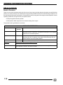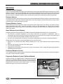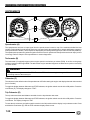
1
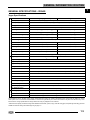
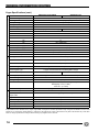
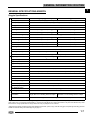
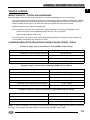
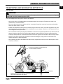
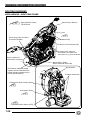
2008
VEGAS® • VEGAS LOW™ • VEGAS 8-BALL™
KINGPIN® • KINGPIN® TOUR • KINGPIN 8-BALL™
SERVICE MANUAL PN 9921242
FOREWORD
This manual is designed primarily for use by Victory service technicians in a properly equipped shop and should be kept
available for reference in the shop area. All references to left and right side of the motorcycle are from the operator's
perspective when seated in a normal riding position.
Some procedures outlined in this manual require a sound knowledge of mechanical theory, tool use, and shop
procedures in order to perform the work safely and correctly. Read the text and be familiar with the service procedures
before starting the work. Certain procedures will require the use of special tools. Use only the proper tools as specified.
If you have any doubt as to your ability to perform any of the procedures outlined in this service manual, contact an
authorized Victory dealer for service.
This manual includes procedures for maintenance, component identification and repair, along with service
specifications for the above model motorcycles. Comments or suggestions about this manual may be directed to:
Service Publications Dept. @ Polaris Sales Inc. 2100 Hwy 55 Medina Minnesota 55340.
© Copyright 2007 Polaris Sales Inc. All information contained within this publication is based on the latest product information at the time of publication. Due to constant
improvements in the design and quality of production components, some minor discrepancies may result between the actual vehicle and the information presented in this
publication. Depictions and/or procedures in this publication are intended for reference use only. No liability can be accepted for omissions or inaccuracies. Any reprinting
or reuse of the depictions and/or procedures contained within, whether whole or in part, is expressly prohibited. Printed in U.S.A.
TRADEMARKS
The following are REGISTERED trademarks of Polaris Industries Inc.:
POLARIS; POLARIS THE WAY OUT; VICTORY MOTORCYCLES; FREEDOM; VEGAS; VEGAS JACKPOT; HAMMER;
KINGPIN; NESS SIGNATURE SERIES VEGAS JACKPOT.
Polaris acknowledges the following products mentioned in this manual:
LOCTITE, is a registered trademark of the Henkel Corporation
DUNLOP, is a registered trademark of the Dunlop Tire Corporation.
STA-BIL, is a registered trademark of Gold Eagle
NYOGEL, is a registered trademark of the William F. Nye Company
FLUKE, registered trademark of the Fluke Corporation
GENERAL INFORMATION / ROUTING
CHAPTER 1
GENERAL INFORMATION / ROUTING
1
GENERAL INFORMATION . . . . . . . . . . . . . . . . . . . . . . . . . . . . . . . . . . . . . . . . . . . . . . . . 1.3
SERVICE RULES . . . . . . . . . . . . . . . . . . . . . . . . . . . . . . . . . . . . . . . . . . . . . . . . . . . . . . . 1.3
SAFETY INFORMATION. . . . . . . . . . . . . . . . . . . . . . . . . . . . . . . . . . . . . . . . . . . . . . . . . . 1.4
UNDERSTANDING SAFETY LABELS & INSTRUCTIONS . . . . . . . . . . . . . . . . . . . . . . . 1.4
GENERAL SPECIFICATIONS - VEGAS . . . . . . . . . . . . . . . . . . . . . . . . . . . . . . . . . . . . . . 1.5
VEGAS SPECIFICATIONS. . . . . . . . . . . . . . . . . . . . . . . . . . . . . . . . . . . . . . . . . . . . . . . . 1.5
VEGAS SPECIFICATIONS (CONT.) . . . . . . . . . . . . . . . . . . . . . . . . . . . . . . . . . . . . . . . . 1.6
GENERAL SPECIFICATIONS-KINGPIN. . . . . . . . . . . . . . . . . . . . . . . . . . . . . . . . . . . . . . 1.7
KINGPIN SPECIFICATIONS . . . . . . . . . . . . . . . . . . . . . . . . . . . . . . . . . . . . . . . . . . . . . . 1.7
KINGPIN SPECIFICATIONS (CONT.) . . . . . . . . . . . . . . . . . . . . . . . . . . . . . . . . . . . . . . . 1.8
VEHICLE LOADING . . . . . . . . . . . . . . . . . . . . . . . . . . . . . . . . . . . . . . . . . . . . . . . . . . . . . 1.9
WEIGHT CAPACITY - TOP BOX AND SADDLEBAGS . . . . . . . . . . . . . . . . . . . . . . . . . . 1.9
LOADING EXAMPLES FOR GROSS VEHICLE WEIGHT RATING (GVWR) - VEGAS . 1.9
LOADING EXAMPLES FOR GROSS VEHICLE WEIGHT RATING (GVWR) - KINGPIN1.10
REFINISHING . . . . . . . . . . . . . . . . . . . . . . . . . . . . . . . . . . . . . . . . . . . . . . . . . . . . . . . . . 1.11
VICTORY TOUCH-UP AND REFINISHING PAINT . . . . . . . . . . . . . . . . . . . . . . . . . . . . 1.11
VICTORY DETAIL AND FINISH RESTORER KITS . . . . . . . . . . . . . . . . . . . . . . . . . . . . 1.11
PAINTING TERMS . . . . . . . . . . . . . . . . . . . . . . . . . . . . . . . . . . . . . . . . . . . . . . . . . . . . . 1.11
PAINT COLORS BY MODEL . . . . . . . . . . . . . . . . . . . . . . . . . . . . . . . . . . . . . . . . . . . . . 1.12
PAINT COLOR CODES . . . . . . . . . . . . . . . . . . . . . . . . . . . . . . . . . . . . . . . . . . . . . . . . . 1.14
VEHICLE INFORMATION . . . . . . . . . . . . . . . . . . . . . . . . . . . . . . . . . . . . . . . . . . . . . . . . 1.15
VEHICLE IDENTIFICATION NUMBER (VIN) . . . . . . . . . . . . . . . . . . . . . . . . . . . . . . . . . 1.15
MODEL NUMBER. . . . . . . . . . . . . . . . . . . . . . . . . . . . . . . . . . . . . . . . . . . . . . . . . . . . . . 1.15
VIN NUMBER LOCATION . . . . . . . . . . . . . . . . . . . . . . . . . . . . . . . . . . . . . . . . . . . . . . . 1.16
MANUFACTURER LABEL . . . . . . . . . . . . . . . . . . . . . . . . . . . . . . . . . . . . . . . . . . . . . . . 1.16
ENGINE NUMBER LOCATION . . . . . . . . . . . . . . . . . . . . . . . . . . . . . . . . . . . . . . . . . . . 1.16
KEY IDENTIFICATION NUMBER. . . . . . . . . . . . . . . . . . . . . . . . . . . . . . . . . . . . . . . . . . 1.16
PUBLICATIONS & TECHNICAL LITERATURE . . . . . . . . . . . . . . . . . . . . . . . . . . . . . . . 1.17
PUBLICATION PART NUMBERS . . . . . . . . . . . . . . . . . . . . . . . . . . . . . . . . . . . . . . . . . 1.17
MATERIAL SAFETY DATA SHEET (MSDS) . . . . . . . . . . . . . . . . . . . . . . . . . . . . . . . . . 1.17
BREAK IN PERIOD . . . . . . . . . . . . . . . . . . . . . . . . . . . . . . . . . . . . . . . . . . . . . . . . . . . . . 1.18
BREAK-IN PROCEDURE . . . . . . . . . . . . . . . . . . . . . . . . . . . . . . . . . . . . . . . . . . . . . . . . 1.18
EMISSIONS . . . . . . . . . . . . . . . . . . . . . . . . . . . . . . . . . . . . . . . . . . . . . . . . . . . . . . . . . . . 1.19
EMISSION CONTROL SYSTEMS . . . . . . . . . . . . . . . . . . . . . . . . . . . . . . . . . . . . . . . . . 1.19
EMISSION SOURCES . . . . . . . . . . . . . . . . . . . . . . . . . . . . . . . . . . . . . . . . . . . . . . . . . . 1.19
EXHAUST EMISSION CONTROL . . . . . . . . . . . . . . . . . . . . . . . . . . . . . . . . . . . . . . . . . 1.19
NOISE EMISSION CONTROL SYSTEM . . . . . . . . . . . . . . . . . . . . . . . . . . . . . . . . . . . . 1.19
CRANKCASE EMISSION CONTROL . . . . . . . . . . . . . . . . . . . . . . . . . . . . . . . . . . . . . . 1.19
EVAPORATIVE EMISSION CONTROL (CALIFORNIA MODELS) . . . . . . . . . . . . . . . . 1.19
INSTRUMENTS . . . . . . . . . . . . . . . . . . . . . . . . . . . . . . . . . . . . . . . . . . . . . . . . . . . . . . . . 1.20
SPEEDOMETER . . . . . . . . . . . . . . . . . . . . . . . . . . . . . . . . . . . . . . . . . . . . . . . . . . . . . . 1.20
TACHOMETER. . . . . . . . . . . . . . . . . . . . . . . . . . . . . . . . . . . . . . . . . . . . . . . . . . . . . . . . 1.20
ODOMETER . . . . . . . . . . . . . . . . . . . . . . . . . . . . . . . . . . . . . . . . . . . . . . . . . . . . . . . . . . 1.20
TRIP ODOMETER . . . . . . . . . . . . . . . . . . . . . . . . . . . . . . . . . . . . . . . . . . . . . . . . . . . . . 1.20
INDICATOR LIGHTS . . . . . . . . . . . . . . . . . . . . . . . . . . . . . . . . . . . . . . . . . . . . . . . . . . . . 1.21
1.1
GENERAL INFORMATION / ROUTING
SPECIAL SERVICE TOOLS . . . . . . . . . . . . . . . . . . . . . . . . . . . . . . . . . . . . . . . . . . . . . . 1.22
GENERAL & PRECISION MEASUREMENT. . . . . . . . . . . . . . . . . . . . . . . . . . . . . . . . .
TUNE UP & MAINTENANCE. . . . . . . . . . . . . . . . . . . . . . . . . . . . . . . . . . . . . . . . . . . . .
ELECTRICAL . . . . . . . . . . . . . . . . . . . . . . . . . . . . . . . . . . . . . . . . . . . . . . . . . . . . . . . . .
ENGINE, CLUTCH, & TRANSMISSION . . . . . . . . . . . . . . . . . . . . . . . . . . . . . . . . . . . .
STEERING & SUSPENSION. . . . . . . . . . . . . . . . . . . . . . . . . . . . . . . . . . . . . . . . . . . . .
WHEEL & TIRE . . . . . . . . . . . . . . . . . . . . . . . . . . . . . . . . . . . . . . . . . . . . . . . . . . . . . . .
FUEL SYSTEM & FUEL INJECTION. . . . . . . . . . . . . . . . . . . . . . . . . . . . . . . . . . . . . . .
TOOL ORDERING INFORMATION. . . . . . . . . . . . . . . . . . . . . . . . . . . . . . . . . . . . . . . .
1.22
1.22
1.22
1.23
1.23
1.24
1.24
1.24
TRANSPORTING AND SECURING THE MOTORCYCLE. . . . . . . . . . . . . . . . . . . . . . . 1.25
GUIDELINES . . . . . . . . . . . . . . . . . . . . . . . . . . . . . . . . . . . . . . . . . . . . . . . . . . . . . . . . . 1.25
ROUTING DIAGRAMS . . . . . . . . . . . . . . . . . . . . . . . . . . . . . . . . . . . . . . . . . . . . . . . . . . 1.26
WIRE HARNESS - RIGHT REAR FRAME . . . . . . . . . . . . . . . . . . . . . . . . . . . . . . . . . .
WIRE HARNESS - RIGHT SIDE . . . . . . . . . . . . . . . . . . . . . . . . . . . . . . . . . . . . . . . . . .
WIRE HARNESS - LEFT SIDE . . . . . . . . . . . . . . . . . . . . . . . . . . . . . . . . . . . . . . . . . . .
WIRE HARNESS - UNDER SEAT . . . . . . . . . . . . . . . . . . . . . . . . . . . . . . . . . . . . . . . . .
1.26
1.27
1.28
1.29
WIRE HARNESS CONNECTOR LOCATIONS. . . . . . . . . . . . . . . . . . . . . . . . . . . . . . . . 1.30
WIRE HARNESS FRONT VIEW . . . . . . . . . . . . . . . . . . . . . . . . . . . . . . . . . . . . . . . . . . 1.30
WIRE HARNESS RIGHT SIDE VIEW / TOP VIEW . . . . . . . . . . . . . . . . . . . . . . . . . . . . 1.31
REFERENCE . . . . . . . . . . . . . . . . . . . . . . . . . . . . . . . . . . . . . . . . . . . . . . . . . . . . . . . . . 1.32
SAE TAP DRILL SIZES . . . . . . . . . . . . . . . . . . . . . . . . . . . . . . . . . . . . . . . . . . . . . . . . .
METRIC TAP DRILL SIZES. . . . . . . . . . . . . . . . . . . . . . . . . . . . . . . . . . . . . . . . . . . . . .
DECIMAL EQUIVALENTS . . . . . . . . . . . . . . . . . . . . . . . . . . . . . . . . . . . . . . . . . . . . . . .
FAHRENHEIT TO CELSIUS . . . . . . . . . . . . . . . . . . . . . . . . . . . . . . . . . . . . . . . . . . . . .
MEASUREMENT CONVERSION CHART. . . . . . . . . . . . . . . . . . . . . . . . . . . . . . . . . . .
1.2
1.32
1.32
1.32
1.33
1.33
GENERAL INFORMATION / ROUTING
1
GENERAL INFORMATION
SERVICE RULES
In order to perform service work efficiently and prevent costly errors, technicians should read the text in this manual and
familiarize themselves with the procedures before beginning. Notes, Cautions and Warnings have been included for
clarification of text and safety concerns. Knowledge of mechanical theory, tool use and shop procedures are necessary
to perform some procedures in this manual safely and correctly.
Use only genuine Victory service parts, including fasteners that require replacement if removed. Do NOT substitute
fasteners or hardware.
Cleanliness of parts and tools as well as the work area is of primary importance. Dirt and foreign matter will cause
damage to precision parts. Clean the motorcycle before beginning service. Clean all parts before installing.
If difficulty is encountered in removing or installing a component, look to see if a cause for the difficulty can be found.
If it is necessary to tap the part into place, use a soft face hammer and tap lightly.
Always follow torque specifications as outlined throughout this manual. Incorrect torquing may lead to serious machine
damage or in the case of steering, driveline, and chassis components, can result in loss of control during operation of
the motorcycle, which may result in severe personal injury or death.
If a torquing sequence is indicated for nuts, bolts or screws of a certain component, start all fasteners and hand tighten.
Following the method and sequence indicated, tighten evenly to the specified torque value. When removing nuts, bolts
or screws from a component with several fasteners, loosen them all about 1/4 turn before removing them to prevent
distortion of that component.
Replace all oil seals, sealing washers, gaskets, and O-rings with new ones during assembly. Be sure the mating surfaces
for the gasket are clean and smooth to avoid leaks and maintain specified tolerances.
Some procedures require removal of retaining rings or clips. Removal can weaken and deform these parts, therefore,
they should always be replaced with new parts. When installing new retaining rings and clips, use care not to expand
or compress them beyond what is required for installation.
Victory lubricants and greases have been specially formulated to provide maximum performance and protection when
applied properly. In some applications, warranty coverage may be void if improper lubricants are used.
Parts requiring grease should be cleaned thoroughly and fresh grease applied before reassembly. Deteriorating grease
loses lubricity and may contain abrasive foreign matter.
Always replace locking hardware such as lock nuts or lock washers, fasteners that have pre-applied locking agent, or
any other fasteners as noted in this service manual with genuine Victory hardware from an authorized Victory dealer.
Working with batteries can be hazardous. Review all battery warnings and cautions. See “BATTERY SAFETY” on
page 16.2.
1.3
GENERAL INFORMATION / ROUTING
SAFETY INFORMATION
Understanding Safety Labels & Instructions
READ AND BECOME FAMILIAR WITH ALL WARNING AND CAUTION SYSMBOLS AND STATEMENTS LISTED
BELOW AND IN THE TEXT OF THIS MANUAL BEFORE YOU BEGIN WORK.
This is the safety alert symbol. When you see this symbol
on the vehicle or in this manual, be alert to the potential
for personal injury. Your safety is involved!
Indicates a hazardous situation, which, if not avoided, could
result in death or serious injury.
Indicates a hazardous situation, which, if not avoided, could
result in minor or moderate injury.
NOTICE:
Indicates a situation, which, if not avoided, could result in
damage to the motorcycle.
Gasoline is extremely flammable and explosive
under certain conditions.
Always stop the engine and refuel outdoors or in a
well ventilated area.
Do not smoke or allow open flames or sparks in or
near the area where refueling is performed or where
gasoline is stored.
Do not overfill the tank. Do not fill the tank neck above
the fuel tank insert. Leave air space to allow for fuel
expansion.
If you get gasoline in your eyes or if you swallow
gasoline, see your doctor immediately. Never try to
syphon gasoline using mouth suction.
If you spill gasoline on your skin or clothing,
immediately wash it off with soap and water and
change clothing.
Never start the engine or let it run in an enclosed area.
Engine exhaust fumes are poisonous and can cause
loss of consciousness or death in a short time.
Improper repairs or service can create
unsafe conditions that may cause severe
personal injury or death.
The engine exhaust from this product
contains chemicals known to cause cancer,
birth defects or other reproductive harm.
Never run the engine in an enclosed area
Modifications to this motorcycle not approved
by Victory may cause loss of performance,
without a properly functioning exhaust gas
evacuation system connected to the product. excessive emissions, and make the machine
unsafe for use.
Wear insulated protection for hands and
arms or wait until hot components have
cooled sufficiently before working on the
product.
Brake fluid is poisonous. Do not ingest or
allow brake fluid to contact eyes. Always
wear eye protection when working with
brake fluid.
Care should be taken to be sure the motorcycle
will not tip or fall while elevated. Severe
personal injury or death could occur if the
motorcycle tips or falls.
1.4
The engine and exhaust components on this
product become very hot during operation
and remain so for a period of time after the
engine is stopped.
Brake fluid is poisonous.
KEEP OUT OF REACH OF CHILDREN.
Battery electrolyte is poisonous. It contains
sulfuric acid. Serious burns can result from
contact with skin, eyes or clothing.
NOTICE
Brake fluid will damage plastic, painted and rubber parts. Protect
these surfaces whenever the brake system is being serviced.
GENERAL INFORMATION / ROUTING
1
GENERAL SPECIFICATIONS - VEGAS
Vegas Specifications
2008 Vegas [Vegas 8-Ball]
C
A
P
A
C
I
T
I
E
S
&D
I
M
E
N
S
I
O
N
S
Oil Capacity
5.0 Qt (4.75 ltr) (Approximately 4.65 qts.or 4.25 ltr at oil & filter change)
Fuel Capacity
4.5 US Gal (17 ltr) (.8 U.S. gal / 3.0 ltr reserve)
Fuel Type / Octane Minimum
Premium Unleaded / 92 Octane
Wheelbase
66.3 in (168.4 cm)
Dry Weight
658 lbs (298 kg) [652 lbs (296 kg)]
651 lbs (295 kg)
Wet Weight
686 lbs (311 kg) [680 lbs (308.4 kg)]
679 lbs (308 kg)
1151 lbs. (522 kg)
1134 lbs. (514 kg)
465 lbs. (211 kg) [465 lbs. (211 kg)]
455 lbs. (206 kg)
Gross Vehicle Weight Rating
Maximum Load Capacity*
Overall Length
96.0 in (243.9 cm)
Overall Width
38 in (97 cm)
38 in (97 cm)
Overall Height
49.40 in (125.4 cm)
49.40 in (125.4 cm)
Seat Height
26.5 in (67.3 cm)
25.2 in (64.0 cm)
Ground Clearance
5.8 in (14.8 cm)
5.3 in (13.5 cm)
1 [ 8-Ball - 0 ]
0
Passenger Capacity
Rake / Trail
Engine Type
32.9 Degrees / 4.9 in. (12.6 cm)
Freedom® 100/6
Freedom® 100/6 V-Twin
V-Twin [8-Ball 100 / 5]
Engine Configuration
50o SOHC Transverse V-Twin 4 Stroke
Engine Displacement
1634cc / 100 cubic
Engine Cooling System
Compression Ratio
E
N
G
I
N
E
2008 Vegas Low
Compression Pressure
Air / Oil
8.7:1
185 - 225 psi (1275 - 1551 kPa)
Valves Train
4 Valves per cylinder. Hydraulic Lifters & Cam Chain Adjusters (No Adjustment)
Bore x Stroke
101 x 102 mm
Starter
Fuel System / Throttle Body
Exhaust System Type
Lubrication System
Spark Plug Type (Gap)
Dry Weight (Engine)
B Brake Type (Front / Rear)
R
A Front Brake
K
E Rear Brake
Electric / Direct Drive
Electronic Fuel Injection / 45 mm
Dual - Large bore slash cut with common volume
Wet Sump
NGK DCPR6E (.032-.036 in. / 0.8-.9 mm)
265 lbs. (120 Kg)
Disc / Disc
Single 300 x 5 mm Floating Disc with 4 Piston Caliper
Single 300 x 5 mm Floating Disc with 2 Piston Caliper
All specifications are for standard Victory Vegas, Vegas 8-Ball, and Vegas Low models. Specifications may change with the addition of custom
order options and / or accessories. Polaris Sales Inc. reserves the right without prior notice to discontinue at any time at its discretion any of the
items herein or change specifications or designs without incurring any obligation to the customer.
* Maximum load capacity includes the weight of all additional accessories, options, cargo, rider with riding gear, and passenger with riding gear. See
GVWR and Vehicle Loading information beginning on page 1.9.
1.5
GENERAL INFORMATION / ROUTING
Vegas Specifications (cont.)
2008 Vegas [Vegas 8-Ball]
D
R
I
V
E
Transmission Type
Manual, 6 Speed Overdrive Constant Mesh [8-Ball - 5 speed]
Clutch Type
Wet, Multi-Plate Diaphragm Spring
Primary Drive Type
Wet, Gear Drive w/ Torque Compensator
Primary Reduction Ratio
Final Drive Type / Final Drive Ratio
Gear Shift Pattern
S
Y Internal Gear Ratios 1st
S
2nd
T
3rd
E
4th
M
5th
1.5:1
28mm Carbon Fiber Reinforced Belt / 2.12:1
1 Down, 5 Up [8-Ball 1 Down, 4 Up]
Front Wheel (Size / Type)
T Rear Wheel (Size / Type)
I
R Front Tire
E Rear Tire
S
Minimum Tread Depth
1 Down, 5 Up
3.15:1
2.03:1
1.53:1
1.24:1
1:1
6th
S
U
S
P
E
N
S
I
O
N
2008 Vegas Low
.84:1 [8-Ball N/A]
Cast or Billet / 2.15 x 21(inch)
Cast or Billet 5.0 x 18 (inch)
Dunlop Elite 3 (90/90 21 Tubeless)
Dunlop D417 (180/55-B18 Tubeless)
.063 in. (1.6mm)
Front Type
43mm Conventional Telescopic Fork
Front Travel
5.1 in. (130 mm)
Front Tube Diameter
43 mm (1.7 in.)
Rear Shock Type
Rear Swingarm Type
Rear Travel (inches)
Headlamp (Intl)
L Brake / Tail Light
I
Turn Signal Light
G
H Instrument Cluster
T
S
Alternator / Battery
Brake / Headlamp
Tail Lamp / Flashers / Indicator
F Lamps / Horn
U
Engine / PCM
S
E Ignition / Gauges
S Fuel Pump
Accessory
Main Circuit Breaker
Single, Monotube Gas w/Adjustable Preload
Forged and Cast Aluminum with Rising Rate Linkage
3.9 in (100 mm)
3.0 in (75 mm)
High: H-7 55W Low: H-11 35W (International - H4)
Non-Serviceable LED
R10W (10W)
Indicator Lights: W2.3W (2.3 Watt Wedge Base)
Backlighting: T10 (1.7 Watt)
Tach: T6.5 (1.7 Watt)
38 amp (Approx 450 Watts) / 12V 18AH 320 CCA
15 amp fuse
Auto Cancel Turn Signal System - 15 amp fuse
15 amp fuse
15 amp fuse
10 amp fuse
15 amp fuse
40 amp circuit breaker
All specifications are for standard Victory Vegas, Vegas 8-Ball, and Vegas Low models. Specifications may change with the addition of custom order
options and / or accessories. Polaris Sales Inc. reserves the right without prior notice to discontinue at any time at its discretion any of the items
herein or change specifications or designs without incurring any obligation to the customer.
1.6
GENERAL INFORMATION / ROUTING
1
GENERAL SPECIFICATIONS-KINGPIN
Kingpin Specifications
2008 Kingpin [Kingpin 8-Ball]
C
A
P
A
C
I
T
I
E
S
&D
I
M
E
N
S
I
O
N
S
Oil Capacity
5.0 Qt (4.75 ltr) (Approximately 4.65 qts.or 4.25 ltr at oil & filter change)
Fuel Capacity
4.5 US Gal (17 ltr) (.8 U.S. gal / 3.0 ltr reserve)
Fuel Type / Octane Minimum
Premium Unleaded / 92 Octane
Wheelbase
65.6 in (166.6 cm)
Dry Weight
676 lbs (307 kg) [670 lbs (304 kg)]
741 lbs (336 kg)
Wet Weight
704 lbs (319 kg) [698 lbs (317 kg)]
769 lbs (349 kg)
Gross Vehicle Weight Rating
Maximum Load Capacity*
1234 lbs. (560 kg)
530 lbs (240 kg) [536 lbs (243 kg)]
465 lbs (211 kg)
Overall Length
99.9 in (253.7 cm)
102.9 in (261.4 cm)
Overall Width
38 in (97 cm)
38 in (97 cm)
Overall Height
49.40 in (125.4 cm)
56.30 in (143 cm)
Seat Height
26.5 in (67.3 cm)
Ground Clearance
5.8 in (14.8 cm)
Passenger Capacity
Engine Type
1
1 [ 8-Ball - 0 ]
Rake / Trail
32.8 Degrees / 5.4 in. (13.8 cm)
Freedom® 100/6
Freedom® 100/6 V-Twin
V-Twin [8-Ball 100 / 5]
Engine Configuration
50o SOHC Transverse V-Twin 4 Stroke
Engine Displacement
1634cc / 100 cubic
Engine Cooling System
Compression Ratio
E
N
G
I
N
E
2008 Kingpin Tour
Compression Pressure
Air / Oil
8.7:1
185 - 225 psi (1275 - 1551 kPa)
Valves Train
4 Valves per cylinder. Hydraulic Lifters & Cam Chain Adjusters (No Adjustment)
Bore x Stroke
101 x 102 mm
Starter
Fuel System / Throttle Body
Exhaust System Type
Lubrication System
Spark Plug Type (Gap)
Dry Weight (Engine)
B Brake Type (Front / Rear)
R
A Front Brake
K
E
S Rear Brake
Electric / Direct Drive
Electronic Fuel Injection / 45 mm
Dual - Large bore slash cut with common volume
Wet Sump
NGK DCPR6E (.032-.036 in. / 0.8-.9 mm)
265 lbs. (120 Kg)
Disc / Disc
Single 300 x 5 mm Floating Disc/4 P Caliper
Dual 300 x 5 mm Floating Disc/4 P Caliper
Single 300 x 5 mm Floating Disc with 2 Piston Caliper
All specifications are for standard Victory Kingpin, Kingpin 8-Ball, and Kingpin Tour models. Specifications may change with the addition of custom
order options and / or accessories. Polaris Sales Inc. reserves the right without prior notice to discontinue at any time at its discretion any of the
items herein or change specifications or designs without incurring any obligation to the customer.
* Maximum load capacity includes the weight of all additional accessories, options, cargo, rider with riding gear, and passenger with riding gear. See
GVWR and Vehicle Loading information beginning on page 1.9.
1.7
GENERAL INFORMATION / ROUTING
Kingpin Specifications (cont.)
2008 Kingpin [Kingpin 8-Ball]
D
R
I
V
E
Transmission Type
Manual, 6 Speed Overdrive Constant Mesh [8-Ball - 5 speed]
Clutch Type
Wet, Multi-Plate Diaphragm Spring
Primary Drive Type
Wet, Gear Drive w/ Torque Compensator
Primary Reduction Ratio
Final Drive Type / Final Drive Ratio
Gear Shift Pattern
S
Y Internal Gear Ratios 1st
S
2nd
T
3rd
E
4th
M
5th
6th
Front Wheel (Size / Type)
T Rear Wheel (Size / Type)
I
R Front Tire
E Rear Tire
S
Minimum Tread Depth
S
U
S
P
E
N
S
I
O
N
2008 Kingpin Tour
1.5:1
28mm Carbon Fiber Reinforced Belt / 2.12:1
1 Down, 5 Up [8-Ball 1 Down, 4 Up]
1 Down, 5 Up
3.15:1
2.03:1
1.53:1
1.24:1
1:1
.84:1 [8-Ball N/A]
Cast or Billet / 3.0 x 18 (inch)
Cast or Billet 5.0 x 18 (inch)
Dunlop 491 Elite ll (130/70 B 18 Tubeless)
Dunlop D417 (180/55-B18 Tubeless)
.063 in. (1.6mm)
Front Type
43mm Inverted Cartridge Telescopic Fork
Front Travel
5.1 in. (130 mm)
Front Tube Diameter
43 mm (1.7 in.)
Rear Shock Type
Single, Monotube Gas w/Adjustable Preload
Rear Swingarm Type
Forged and Cast Aluminum with Rising Rate Linkage
Rear Travel (inches)
3.9 in (100 mm)
Headlamp (Intl)
L Brake / Tail Light
I
Turn Signal Light
G
H Instrument Cluster
T
S
Alternator / Battery
Brake / Headlamp
Tail Lamp / Flashers / Indicator
F Lamps / Horn
U
Engine / PCM
S
E Ignition / Gauges
S Fuel Pump
Accessory
Main Circuit Breaker
High: H-7 55W Low: H-11 35W (International - H4)
Non-Serviceable LED
R10W (10W)
Indicator Lights: W2.3W (2.3 Watt Wedge Base)
Backlighting: T10 (1.7 Watt)
Tach: T6.5 (1.7 Watt)
38 amp (Approx 450 Watts) / 12V 18AH 320 CCA
15 amp fuse
Auto Cancel Turn Signal System - 15 amp fuse
15 amp fuse
15 amp fuse
10 amp fuse
15 amp fuse
40 amp circuit breaker
All specifications are for standard Victory Kingpin, Kingpin 8-Ball, and Kingpin Tour models. Specifications may change with the addition of custom
order options and / or accessories. Polaris Sales Inc. reserves the right without prior notice to discontinue at any time at its discretion any of the
items herein or change specifications or designs without incurring any obligation to the customer.
1.8
GENERAL INFORMATION / ROUTING
1
VEHICLE LOADING
WEIGHT CAPACITY - TOP BOX AND SADDLEBAGS
When operating a motorcycle with original equipment or accessory saddlebags and / or top box (trunk):
• Never ride at speeds exceeding 80 mph (129 km/h). Depending on load and weather conditions, the maximum
safe operating speed may be less than 80 mph (129 km/h). Saddlebags and / or top box, combined with the
lifting or buffeting effects of wind, can make the motorcycle unstable and cause loss of control.
• Distribute weight evenly in each of the saddlebags.
• Do not exceed the maximum cargo weight limit of original equipment or accessory saddlebags or trunk.
Leather, semi-hard, or hard saddlebags weight capacity: 7 lbs (3.2 kg) each
Top box weight capacity: 20 lbs (9 kg)
• Do not exceed the motorcycle’s Gross Vehicle Weight Rating (GVWR). Exceeding the weight capacity can
reduce stability and handling and cause loss of control.
LOADING EXAMPLES FOR GROSS VEHICLE WEIGHT RATING (GVWR) - VEGAS®
Example 1: Vegas® with no accessories or cargo (GVWR 1151 lbs / 522 kg)
Item
Weight
Motorcycle - with full capacity of all fluids
686 lbs (311 kg)
Operator - with recommended riding apparel
230 lbs (104 kg)
Passenger - with recommended riding apparel.
165 lbs (75 kg)
Total Weight
1081 lbs (490 kg)
Example 2: Vegas® with accessory saddlebags (GVWR 1151 lbs / 522 kg)
Item
Weight
Motorcycle - with full capacity of all fluids
Weight of leather saddlebags and brackets
Cargo - optional saddlebags at capacity
686 lbs (311 kg)
12 lbs (5.5 kg)
14 lbs
(6 kg)
Operator - with recommended riding apparel
230 lbs (104 kg)
Passenger - with recommended riding apparel
165 lbs (75 kg)
Total Weight
1107 lbs (502 kg)
Example 3: Vegas Low™ with no accessories or cargo (GVWR 1134 lbs / 514 kg)
Item
Weight
Motorcycle - with full capacity of all fluids
679 lbs (308 kg)
Operator - with recommended riding apparel
230 lbs (104 kg)
Total Weight
909 lbs (412 kg)
NOTE: As shown in Example 2, the weight of any accessory items (leather saddlebags and brackets) in addition to
the cargo, must be added to the base weight of the motorcycle. NEVER exceed GVWR.
1.9
GENERAL INFORMATION / ROUTING
LOADING EXAMPLES FOR GROSS VEHICLE WEIGHT RATING (GVWR) - KINGPIN®
Example 4: Kingpin® with no accessories or cargo (GVWR 1234 lbs / 560 kg)
Item
Weight
Motorcycle - with full capacity of all fluids
704 lbs (319 kg)
Operator - with recommended riding apparel
230 lbs (104 kg)
Passenger - with recommended riding apparel.
165 lbs (75 kg)
Total Weight
1099 lbs (498 kg)
Example 5: Kingpin® Tour with cargo (GVWR 1234 lbs / 560 kg)
Item
Weight
Motorcycle - with full capacity of all fluids
769 lbs (349 kg)
Cargo - top box at capacity
20 lbs (9 kg)
Cargo - saddlebags at capacity
14 lbs (6 kg)
Operator - with recommended riding apparel
230 lbs (104 kg)
Passenger - with recommended riding apparel
165 lbs (75 kg)
Total Weight
1198 lbs (543 kg)
NOTE: The weight of any accessory items such as saddlebags and brackets that are not standard equipment, or
individual items in addition to the cargo, must be added to the base weight of the motorcycle. NEVER exceed GVWR.
1.10
GENERAL INFORMATION / ROUTING
1
REFINISHING
Victory Touch-Up and Refinishing Paint
Service Paint products are available in three different sizes and applications. Some paint colors require up to 3 components to create a color. Prices subject to change without notice. Dealer is responsible for freight on paint and paint
products.
.6 ounce bottle: (Order Multiple of 2) For brush touch-up of small nicks.
10 ounce aerosol can: (Order Multiple of 2)
Apply light even coats for best results. Recoat time is from 30-60 minutes or after 4 days of drying to prevent lifting.
Quarts: (Sold as each)
For repaint of properly prepared plastic components or metal substrates.
Paint is a high quality acrylic urethane manufactured by U.S. Paint.
Mix as indicated on back of paint can. Paint can be recoated after paint is tack free or has ”flashed off”.
Paint finish may be wet sanded and buffed after coating has cured.
How to order:
Authorized Victory Dealers only. Place your order via the dealer web site at:
www.polarisdealers.com / News Forms & Links / Pure Polaris
NOTE: There will be a 25% service fee charged for all returns. Polaris dealer will be responsible for return
freight
Victory detail and finish restorer kits
A Detail Kit (polish, wax, and dressing) and a Restore Kit (polish, and swirl / scuff remover) is available from the Victory parts department for painted surface protection and to remove minor surface imperfections.
Detail Kit: 2872195 Includes Non-Abrasive Wash, Swirl Remover / Polish, Polywax Final Finish, Vinyl / Rubber
Protector, Applicator and Cloth.
Restore / Polish: 2872192 (12 oz. Aerosol)
Painting Terms
The following terms describe the general operations referred to in the Paint Color Code chart on page 1.14.
E-Coat (Factory Applied): This material is used as a rust protection. It is also used to form a bond between bare metal
and the primer or base coat. Full-hide colors (such as black) do not require primer.
Primer: Primer is necessary when applying some colors such as Flame Yellow, Sonic Blue, Solar Red, etc. The purpose
of a primer coat is to prevent bleed-through or transparency in subsequent color coats.
Base Coat: A color paint layer applied under another color or under the clear topcoat to improve color matching and
consistency.
Top Coat: Outermost layer of paint or clear coat.
1.11
GENERAL INFORMATION / ROUTING
Paint Colors by Model
Refer to www.polarisdealers.com for more information.
The 9th letter of the model number designate the color. “P” in the 10th position indicates Premium model. Premium
models could be equipped with billet wheels, chrome package, HID headlamp, etc.
NOTE: Refer to page 1.14 for paint color code. Detailed paint ordering information is available on the dealer
web site at News, Forms & Links / Pure Polaris / Paint Codes & Part Numbers. Refer to page 1.15 for model
number descriptor.
VEGAS® MODEL YEAR 2008
Model Number
Model
V08GB26CA, CAP
Vegas, CND, Solid Black
V08GB26DA, DAP
Vegas, 49st, Solid Black
V08GB26LA, LAP
Vegas, CAL, Solid Black
V08GB26CC, CCP
Vegas, CND, Midnight Cherry
V08GB26DC, DCP
Vegas, 49st, Midnight Cherry
V08GB26LC, LCP
Vegas, CAL, Midnight Cherry
V08GB26CD
Vegas, CND, Steel Gray
V08GB26DD
Vegas, 49st, Steel Gray
V08GB26LD
Vegas, CAL, Steel Gray
V08GB26CFP
Vegas, CND, Blue / Black
V08GB26DFP
Vegas, 49st, Blue / Black
V08GB26LFP
Vegas, CAL, Blue / Black
V08GB26CGP
Vegas, CND, Red / Flame
V08GB26DGP
Vegas, 49st, Red / Flame
V08GB26LGP
Vegas, CAL, Red / Flame
V08GB26UG
Vegas, UK, Red / Flame
VEGAS
LOW™
Model Number
Model
V08LB26CA, CAP
Vegas Low, CND, Solid Black
V08LB26DA, DAP
Vegas Low, 49st, Solid Black
V08LB26LA, LAP
Vegas Low, CAL, Solid Black
V08LB26CC, CCP
Vegas Low, CND, Midnight Cherry
V08LB26DC, DCP
Vegas Low, 49st, Midnight Cherry
V08LB26LC, LCP
Vegas Low, CAL, Midnight Cherry
V08LB26UC
Vegas Low, UK, Midnight Cherry
V08LB26CE, CEP
Vegas Low, CND, Boardwalk Blue
V08LB26DE, DEP
Vegas Low, 49st, Boardwalk Blue
V08LB26LE, LEP
Vegas Low, CAL, Boardwalk Blue
VEGAS 8-BALL® MODEL YEAR 2008
Model Number
Model
V08AB26CA
Vegas 8-Ball, CND, Black
V08AB26DA
Vegas 8-Ball, 49st, Black
V08AB26LA
Vegas 8-Ball, CAL, Black
1.12
GENERAL INFORMATION / ROUTING
1
KINGPIN® MODEL YEAR 2008
Model Number
Model
V08CB26CA, CAP
Kingpin, CND, Black
V08CB26DA, DAP
Kingpin, 49st, Black
V08CB26LA, LAP
Kingpin, CAL, Black
V08CB26CC
Kingpin, CND, Midnight Cherry
V08CB26DC
Kingpin, 49st, Midnight Cherry
V08CB26LC
Kingpin, CAL, Midnight Cherry
V08CB26CD
Kingpin, CND, Steel Gray
V08CB26DD
Kingpin, 49st, Steel Gray
V08CB26LD
Kingpin, CAL, Steel Gray
V08CB26CHP
Kingpin, CND, Sands Metallic / Black
V08CB26DHP
Kingpin, 49st, Sands Metallic / Black
V08CB26LHP
Kingpin, CAL, Sands Metallic / Black
V08CB26CIP
Kingpin, CND, Black / Flame
V08CB26DIP
Kingpin, 49st, Black / Flame
V08CB26LIP
Kingpin, CAL, Black / Flame
KINGPIN® TOUR MODEL YEAR 2008
Model Number
Model
V08CD26CA
Kingpin Tour, CND, Black
V08CD26DA
Kingpin Tour, 49st, Black
V08CD26LA
Kingpin Tour, CAL, Black
V08CD26CC
Kingpin Tour, CAN, Midnight Cherry
V08CD26DC
Kingpin Tour, 49st, Midnight Cherry
V08CD26LC
Kingpin Tour, CAL, Midnight Cherry
V08CD26CD
Kingpin Tour, CAN, Steel Gray
V08CD26DD
Kingpin Tour, 49st, Steel Gray
V08CD26LD
Kingpin Tour, CAL, Steel Gray
V08CD26CH
Kingpin Tour, CAN, Sands Metallic / Black
V08CD26DH
Kingpin Tour, 49st, Sands Metallic / Black
V08CD26LH
Kingpin Tour, CAL, Sands Metallic / Black
V08CD26CI
Kingpin Tour, CAN, Black / Flame
V08CD26DI
Kingpin Tour, 49st, Black / Flame
V08CD26LI
Kingpin Tour, CAL, Black / Flame
V08CD26UI
Kingpin Tour, UK, Black / Flame
KINGPIN 8-BALL™ MODEL YEAR 2008
Model Number
Model
V08PB26CA
Kingpin 8-Ball, CAN, Black
V08PB26DA
Kingpin 8-Ball, 49st, Black
V08PB26LA
Kingpin 8-Ball, CAL, Black
V08PB26UA
Kingpin 8-Ball, UK, Black
1.13
GENERAL INFORMATION / ROUTING
PAINT COLOR CODES
PAINT COLOR: 2008
PAINT CODE
Cruiser Black (PHAT)
P-266
Turbo Silver
P-445
Flat Black
P-463
Sunset Red
P-520
Boardwalk Blue
P-524
Ness Metallic Purple
P-543
Supersteel Gray
P-553
Midnight Cherry
P-554
Sands Metallic
P-555
Anodized Aluminum
P-565
Metallic Flake Additive
METALLIC
Add vial of flake to quart of clear base
Silver Undercoater
SU
Base coat only
Antares Red Undercoater
RU
Base coat only
Clear
C
Clear Metallic
CM
Clear with metal flake added
Clear Pearl
CP
Clear with pearl flake added
UNDERCOATERS
(Base Coat Only)
WU, OWU,
PWU, VVU
WU=White Undercoater; OWU=Off-White Undercoater;
PWU=Pearl White Undercoater; VVU=Victory Violet Undercoater
1.14
NOTES
Paint kits require base coat with a topcoat of Clear Metallic (CM)
Requires P-519 Clear Pearl Topcoat
Requires P-519 Clear Pearl Topcoat
(Kingpin Only)
GENERAL INFORMATION / ROUTING
1
VEHICLE INFORMATION
Vehicle Identification Number (VIN)
See “VIN NUMBER LOCATION” on page 1.16. for location on the vehicle.
SAE-assigned
World Manufacturing
Identifier
Chassis:
A = Vegas 8-Ball
B = Ness Vegas Jackpot
C = Kingpin
G = Vegas
H = Hammer
L = Vegas Low
P = Kingpin 8-Ball
S = Victory Vision
X = Jackpot
Type:
B = Standard
C = Custom
D = Deluxe / Tour
S = Sport
Series:
C = Canada
D = Domestic (49 State)
L = California
U = United Kingdom
Serial Number
*5VPLB26D083000000*
Engine Size:
1 = 1507 cc
2 = 1634 cc
3 = 1731 cc
Engine HP:
6 = 78-94
Check Digit
(May be a number
or a letter)
Model Year:
8 = 2008, etc.
Plant/ Line
Code
(Spirit Lake, IA)
Model Number
See “MANUFACTURER LABEL” on page 1.16. for location on vehicle. See “Paint Colors by Model” on page 1.12. for
color.
Chassis:
A = Vegas 8-Ball
B = Ness Vegas Jackpot
C = Kingpin
G = Vegas
H = Hammer
L = Vegas Low
P = Kingpin 8-Ball
S = Victory Vision
X = Jackpot
Engine Size:
1 = 1507 cc
2 = 1634 cc
3 = 1731 cc
Engine HP:
6 = 78-94
Series:
C = Canada
D = Domestic (49 State)
L = California
U = United Kingdom
P = Premium Model
(Premium may have billet wheels,
HID headlight, chrome package,
or other options as specified)
V08CB26DAP
Victory
Model Year:
08 = 2008, etc.
Type:
B = Standard
C = Custom
D = Deluxe / Tour
S = Sport
Color Indicator
1.15
GENERAL INFORMATION / ROUTING
VIN NUMBER LOCATION
ENGINE NUMBER LOCATION
The vehicle identification number (A) is stamped on the
right side of the steering head.
The engine number (C) is stamped into the right crankcase
boss. The stamping identifies the engine model and serial
number.
A
C
MANUFACTURER LABEL
KEY IDENTIFICATION NUMBER
The manufacturer label (B) located on the left frame tube
contains the following information:
The key identification number (D) is stamped on the key
tag. If the key and the identification number are lost or
misplaced, the lock set (ignition switch / fuel cap) must be
replaced.
VIN Number
Gross Vehicle Weight Rating (GVWR)
Gross Axle Weight Rating (GAWR)
Key blanks are available from Victory. Locksmiths familiar
with the motorcycle industry will be able to cut a
replacement key with the key I.D. number and a Victory key
blank.
B
D
1.16
GENERAL INFORMATION / ROUTING
1
PUBLICATIONS & TECHNICAL LITERATURE
Publication Part Numbers
Some Victory publications, such as Owner’s Manuals and Parts Books are available on-line and can be downloaded
from the Victory motorcycles web site (http://www.polarisindustries.com/en-us/Victory/). Click on the Riders pull down
menu and select Manuals and Parts.
Service Manuals can be purchased through any authorized Victory motorcycle dealer. The part numbers are listed in
the following table. Some manuals are available for purchase on-line at www.purepolaris.com.
VICTORY SERVICE MANUAL PART NUMBERS
2002 - 2006 Classic & Touring Cruiser
9919632
2003-2006 Vegas / Kingpin / 8-Ball /
Ness Signature Series Vegas & Kingpin
9920337
2005-2006 Hammer / 2006 Vegas Jackpot
9920340
2007 Vegas / Vegas 8-Ball / Kingpin / Kingpin Tour
9920837
2007 Hammer / Hammer S / Vegas Jackpot /
Ness Signature Series Vegas Jackpot
9920838
2008 Hammer / Hammer S / Vegas Jackpot /
Ness Signature Series Vegas Jackpot
9921247
2008 Victory Vision
9921254
Material Safety Data Sheet (MSDS)
To review or print a Material Safety Data Sheet for Victory maintenance products, chemicals or lubricants:
DEALERS: visit www.polarisdealers.com / news forms & links / pure polaris OR contact Dealer Support
NON-DEALERS: please contact Polaris Customer Service at: 1-888-704-5290 (French speaking 1-204-925-7100)
1.17
GENERAL INFORMATION / ROUTING
BREAK IN PERIOD
Break-In Procedure
There is never a more important period in the life of a new Victory motorcycle than the period between zero and 500 miles
(805 km). A Victory motorcycle is manufactured using the best possible materials and manufacturing techniques, but
the final machining process is the break-in. During break-in period, many parts in the engine wear and polish to correct
operating clearances. During this time, the operator should:
• Avoid prolonged full throttle operation.
• Avoid operation which might result in excessive heating of the engine.
The general break-in guidelines are as follows:
BREAK-IN GUIDELINES
Miles/km
Throttle
Position
Notes
0-90 miles
0-1/3
Avoid prolonged operation above 1/3 throttle. Stop engine and let it cool
following every hour of operation. Vary speed of motorcycle. Do not operate
machine at one set throttle position.
90-300 miles
0-1/2
Avoid prolonged operation above 1/2 throttle. Stop engine and let it cool
following every hour of operation. Vary speed of the motorcycle. Do not
operate machine at one set throttle position.
300-500 miles
0-3/4
Avoid cruising speeds above 3/4 throttle.
500 miles
Replace the engine oil and engine oil filter. Perform 500 mile service on the machine.
See chapter 2 for more information.
500 +
Avoid prolonged full-throttle operation. Vary the engine speed occasionally. Follow the preride inspection outlined in the owner's manual.
1.18
GENERAL INFORMATION / ROUTING
1
EMISSIONS
Emission Control Systems
The U.S. Environmental Protection Agency and California Air Resources Board (CARB) require manufacturers to certify
that their motorcycles comply with applicable exhaust emissions standards during their useful life, and that motorcycles
built after January 1, 1983 comply with applicable noise emission standards for one year or 6,000 km (3,730 mi) after
the time of sale to the ultimate purchaser, when operated and maintained according to the instructions provided.
Emission Sources
An internal combustion engine produces carbon monoxide and hydrocarbons during operation. Hydrocarbons must be
controlled because under some conditions hydrocarbons react with sunlight to produce photochemical smog. Carbon
monoxide must be controlled because it is toxic.
Exhaust Emission Control
Victory Motorcycles have an electronic engine management system which controls fuel delivery and ignition timing to
control hydrocarbon and carbon monoxide emissions. Except for TPS adjustments as required by the Periodic
Maintenance Interval Table on page 2.6 or if components are replaced that affect idle speed, no adjustments should be
made to the system.
Noise Emission Control System
Tampering with Noise Control Systems is Prohibited. Federal law prohibits the following acts or causing thereof:
1. The removal or rendering inoperative by any person other than for purposes of maintenance, repair or
replacement, any device or element of design incorporated into the motorcycle for the purpose of noise control prior
to its sale or delivery to the ultimate purchaser or while it is in use, or
2. The use of the motorcycle after such device or element of design has been removed or rendered inoperative.
Among those acts presumed to constitute tampering are the acts listed below:
1. Removal of, or puncturing the muffler, baffles, header pipes or any other component which conducts exhaust
gases.
2. Removal or puncturing of any part of the intake system.
3. Lack of proper maintenance.
4. Replacing any moving part of the motorcycle or parts of the exhaust / intake system with parts other than those
specified by the manufacturer.
Crankcase Emission Control
The crankcase emission control system is comprised of a closed system that routes crankcase emissions through the
air cleaner into the combustion chamber.
Evaporative Emission Control (California Models)
California models are equipped with an Evaporative Emissions
Canister (A). Activated charcoal inside the canister temporarily
stores fuel vapor from the fuel tank vent system until the engine is
started and the motorcycle is driven. Refer to page 5.7 for system
diagram and page 2.19 for system maintenance.
A
1.19
GENERAL INFORMATION / ROUTING
INSTRUMENTS
A
B
C
D
E
F
Speedometer (A)
The speedometer receives an input signal from the speed sensor located on top of the crankcase behind the rear
cylinder. Pulse signals from the speed sensor are converted inside the speedometer to speed and distance outputs in
miles (kilometers in Canada). These outputs are displayed by the analog needle (speed) or in the LCD window (distance).
The speedometer operates only when the ignition switch is in the On position and the speed sensor has an input (vehicle
is moving). Refer to Chapter 19 for speedometer or sensor diagnostics.
Tachometer (B)
The tachometer (if equipped) reports current engine speed in revolutions per minute (RPM). A red line on the gauge
indicates maximum safe engine RPM. The tachometer may be standard equipment or added as an option or accessory
on some models.
WARNING
Do not operate the engine over redline RPM. Excessive RPM could cause engine damage or failure that could result
in you losing control of the motorcycle.
Odometer (C)
The odometer is the default mode of the speedometer LCD after starting the engine and displays the total miles traveled
(km in Canada).
To toggle the display between Odometer and TRIP Odometer, the ignition switch must be in the ON position. Press the
reset button (E). The display changes to “TRIP".
Trip Odometer (D)
The trip odometer shows total distance traveled since the trip odometer was reset.
To toggle the display between Odometer and TRIP Odometer, the ignition switch must be in the ON position. Press the
reset button. The display changes to TRIP.
To reset the trip odometer, the ignition switch must be in the ON position with the display in trip odometer mode. Press
and hold the reset button (E) until the TRIP odometer display resets to zero.
1.20
GENERAL INFORMATION / ROUTING
1
INDICATOR LIGHTS
1
2
3
7
4
#
5
6
SYMBOL / FUNCTION
NEUTRAL INDICATOR
1
HEADLAMP HIGH BEAM
2
OPERATION
The neutral indicator illuminates when the transmission is in Neutral, and the ignition key
is ON.
The headlamp high beam indicator illuminates when the headlamp switch is set to High
and the ignition key is ON.
3
The check engine indicator will illuminate any time the ignition key is ON and the engine
control module sensors report abnormal sensor or engine operation. The check engine
indicator will continue to illuminate as long as the fault condition exists. It also illuminates
momentarily when the ignition key is ON and the engine is not running. This
demonstrates that the indicator is functioning properly.
4
The low oil pressure indicator illuminates when engine oil pressure drops below safe
operating pressure. If this indicator illuminates while the engine is running, turn the
LOW OIL PRESSURE INDICATOR engine off immediately and check the oil level. Add oil if necessary. If the oil level is
correct and the indicator remains illuminated after the engine is restarted, turn the
engine off immediately.
The low oil pressure indicator also illuminates when the ignition key is ON and the engine
is not running. This demonstrates that the indicator is functioning properly.
5
The turn signal indicator flashes when the left, right, or both turn signals are active. If
a turn signal bulb has failed, or if there is a short circuit in the turn signal system, the turn
signal indicator flashes at more than twice the normal rate.
This indicator is also used as the output display for the diagnostic “blink codes” when
using the self-diagnostic feature of the Auto-Cancel Turn Signal system. Refer to
Chapter 9 for more information on the self diagnostic feature.
CHECK ENGINE INDICATOR
TURN SIGNAL INDICATOR
LOW FUEL INDICATOR
6
OVERDRIVE INDICATOR
7
The low fuel indicator illuminates when approximately 0.6 gallons (2.27 liters) of fuel
remains in the fuel tank and the ignition key is ON.
On vehicles equipped with a tachometer, the overdrive indicator is illuminated when the
transmission is in Overdrive (6th gear) and the ignition key is ON.
1.21
GENERAL INFORMATION / ROUTING
SPECIAL SERVICE TOOLS
GENERAL & PRECISION MEASUREMENT
TOOL
PART NUMBER
Bearing & Seal Driver Set
PV-43558
Bore Gauge Set, 50-100mm
PV-3017
Decal, Service Bulletin Completion
Dial Caliper (Metric, 0-150mm)
Dial Caliper (Electronic Conversion. English 0-6” / Metric 0-150mm)
Dial Indicator, Adjustable (Metric. 10mm travel)
7170107
(Order from Victory Parts Dept.)
PV-26900-7
PV-39776
PV-26900-12
Dial Indicator Stand, Flexible. Magnetic Base
PV-34481
Engine Ear Listening Device
PV-39565
Feeler Gauge Set
Outside Micrometer (0-25 & 25-50mm)
Outside Micrometer Set (0-100mm)
Plastigauge
®
Small Hole Gauge Set
Straight Edge, Precision
Surface Plate
PV-26900-8 or PV-26900-9
PV-3006, PV-3007
PV-3009
Commercially Available
Commercially Available
PV-34673
Commercially Available
Telescoping Gauge Set
PU-45423
Torque Wrench (3/8” Drive 0-50 in-lb. beam type)
PV-43543
Torque Wrench (1/2” Drive 0-150 lb-ft. beam type)
PV-43552
Torque Wrench (3/8” Drive 15-100 lb-ft. click type)
PV-43564
TUNE UP & MAINTENANCE
TOOL
Belt Tension Gauge
PART NUMBER
PV-43532
Cylinder Leakdown Tester
PV-35667-A
Compression Gauge Set
PV-33223
Oil Pressure Gauge Set
Oil Filter Wrench
PV-43531
65mm/2.5in. Commercially available
ELECTRICAL
TOOL
PART NUMBER
Ammeter Inductive Clamp for Fluke 73™ Multimeter
PV-39617
Electrical Connector Test Adapter Kit
PV-43526
Inductive Timing Light
PV-43537
Multimeter, Fluke 73™
PV-43546
1.22
GENERAL INFORMATION / ROUTING
1
ENGINE, CLUTCH, & TRANSMISSION
TOOL
Clutch Shaft Bearing Support
(for clutch shaft installation)
Crankcase Assembly Tool (Crankcase Installer)
Crankcase Assembly Tool Adapter
PART NUMBER
PV-47331
PV-46299 (Must be used with PV-45030) and
Adapter (Extension) PVX-47429
PVX-47429
Crankshaft Bearing Protector
PV-47207
Crankshaft Rotation Tool
PV-48736
Crankcase Separator (Crankcase Removal)
Engine Hoist or Lift
Engine Lock Tool
Engine Stand
PV-47332-A
Commercially Available
PV-43502-A
Commercially Available
Flywheel Puller
PV-43533
Mainshaft (Clutch Shaft) Holder
PV-45028
Crankcase Installation Tool (Crankcase Assembly)
Moly Assembly Paste (Premium Starter Grease)
Mainshaft (Output Shaft) Seal Installation Tool
Piston Ring Compressor (97mm +)
Split Gear Line-Up Tool
Valve Spring Compressors (Adapter is PV-43513-A)
PV-46299 (Must be used with PV-45030)
PN 2871460
(Order from Victory Parts Dept.)
PV-43505
Includes PV-43570-1 Pliers, PV-43570-2 Band
(3 5/8” to 3 7/8”)
Any 1/4” shaft: Example: 1/4” drill bit shank.
PV-1253 or PV-4019 (Quick Release)
STEERING & SUSPENSION
TOOL
Blind Bearing Remover Set
Cartridge Shaft Holder (Kingpin / Hammer)
Damper Rod Holder (Vegas)
Fork Oil Level Gauge
Fork Seal Driver 43mm, Inverted (Kingpin / Hammer)
Fork Seal Driver, 43mm, Conventional (Vegas)
Fork Seal Guide Tool, 43mm (Kingpin, Vegas)
Steering Bearing, Wheel Bearing Installation Set
Steering Stem Bearing Removal Tool (Lower)
Steering Stem Bearing Adjustment Socket
Steering Stem Bearing Spanner Wrench
Shock Absorber Pre-Load Adjustment Spanner
Shock Spring Compressor
PART NUMBER
PV-43551
PV-47060
PV-43517
PV-59000-A
PV-47035
PV-47036
PV-47037
PV-43515
PV-44683
PV-43508
PV-43509
PV-46993
PV-43571
1.23
GENERAL INFORMATION / ROUTING
WHEEL & TIRE
TOOL
PART NUMBER
PV-48909 (Victory Air Pump & Gauge) Or
Commercially Available Tire Pressure Gauge
Air Pressure Gauge
Tire Bead Breaker
(May be part of the tire removal equipment being used)
Commercially Available
Tire Mounting Lubricant
Commercially Available
Tire Removal Equipment
Commercially Available
Rim Protector
PV-43536
Wheel Balancing/Truing Stand
Commercially Available
FUEL SYSTEM & FUEL INJECTION
SPECIAL TOOLS- FUEL SYSTEM/ FUEL INJECTION
PART NUMBER
(See Chapter 5 for more information)
Victory/Polaris Diagnostic Tool Kit w/ Diagnostic Software
PV-46085
Smart Link Module Kit (New for 2008 models)
PU-47471
Smart Link Module (PU-47468)
PU-47471 (above) includes items at right
(items are available separately)
Vehicle Interface Cable (PU-47469)
PC Interface Cable (PU-47470)
Fuel Pressure Gauge
PV-43506
Fuel Pressure Gauge Adapter
PV-48656
Laptop Computer (Refer to diagnostic software user manual
or HELP section for minimum specifications
Commercially Available
TOOL ORDERING INFORMATION
Order Special Service Tools from SPX Corporation (Phone 800-328-6657 / FAX 586-578-7375) or use the link on the
Victory Dealer Web site.
If you are not a Victory dealer use the phone or FAX number listed above or visit http://polaris.spx.com/
1.24
GENERAL INFORMATION / ROUTING
1
TRANSPORTING AND SECURING THE MOTORCYCLE
GUIDELINES
WARNING
Care should be taken to be sure the motorcycle will not tip or fall while elevated. Severe personal injury or
death could occur if the motorcycle tips or falls.
If you must transport the motorcycle or secure it to a lift table:
• Use a truck, trailer, or lift table designed or equipped properly for motorcycles. Review truck, trailer or lift
manufacturer’s recommendations.
• Do not tow the motorcycle with another vehicle, as towing will impair the motorcycle’s steering and handling,
which can cause a loss of control.
• Position and restrain the motorcycle so it remains upright on the truck, trailer, or lift table as gasoline may leak
out of the fuel tank vent if the motorcycle is transported at extreme angles. Gasoline is a fire hazard and it can
also damage the motorcycle’s finish.
• Do not restrain the motorcycle using the handlebars. Loosen the turn signals and slide them up the fork tube as
shown, enough to make room for a soft tie-down extension strap (no buckles). Place tie downs around the
lower triple clamp as shown, around the fork tube below the turn signal mount and above the lower triple clamp.
• Secure the rear of the motorcycle with tiedowns around the swingarm, being careful to avoid brake lines,
exhaust, drive belt, or drive belt guards.
• Use a platform jack with a wide stable base that securely supports the motorcycle under the flat portion of the
crankcase and frame.
Loosen turn signal mount and slide up
for soft-tie strap clearance.
Both sides
Both sides
Platform jack with wide base and support platform.
Use when elevating the rear wheel.
1.25
GENERAL INFORMATION / ROUTING
ROUTING DIAGRAMS
WIRE HARNESS - RIGHT REAR FRAME
= Apply Dielectric Grease
P/N 2871329
Harness clip in RH hole
Horn
Secure purge valve connector
to harness (49 State)
Harness clip
Idle Air Control Harness (IAC)
NO DIELECTRIC GREASE
OR OTHER CONTAMINANTS
ALLOWED ON O2 SENSOR WIRES
Secure to brake line
bracket (ACC connector)
Starter Motor + Cable
Route underneath brake clips
Route starter cable and voltage
regulator bundle inside brake line
bracket through suspension pivot
bracket (spider bracket).
Transmission (Gear Position) Switch
Oil Pressure Switch
Crankshaft Position Sensor (CPS)
1.26
Speed Sensor
P-clamps toward case
GENERAL INFORMATION / ROUTING
1
WIRE HARNESS - RIGHT SIDE
Clip to frame peg
Clip
Install harness clip on rear side of bracket
Fuel Pump
Clip
Diagnostic Connector
Turn Signal
Auto Cancel Module
(Under battery box)
Rear Brake Light Switch
(connect to switch then
tie strap to starter cable)
Route voltage regulator bundle through
clip and insert into hole on bracket
Gear Position Switch
CPS Wire Guide
Speed Sensor
P-Clips
Tie Strap
Starter +
Cable
1.27
GENERAL INFORMATION / ROUTING
WIRE HARNESS - LEFT SIDE
NO DIELECTRIC GREASE
OR OTHER CONTAMINANTS
ALLOWED ON O2 SENSOR WIRES
OR ENGINE HARNESS CONNECTOR
Front Coil Wire
(Routed through tie strap)
Ignition Bundle Routes Through Clip
(Dart Clip Secured To Inside Of Bracket)
Rear Coil Wire Routed Through Tie Strap
Front Coil Wire To Bottom Coil
Battery +
Battery Circuit Breaker
Starter Solenoid
Turn Signal Auto Cancel Module
Secure battery ground cable and
O2 sensor wire in dart strap on
front of bracket (See exhaust removal, Ch. 3)
Stator Wire 3-Pin Connector
Tie Strap Secures O2 Sensor Wire
& DC 2-Pin Connector
Tie Strap O2 To Inside Of
Left Frame Down Tube
1.28
GENERAL INFORMATION / ROUTING
1
WIRE HARNESS - UNDER SEAT
Chassis Ground (M6x15 Flange Head)
9.6 Nm (85 lb-in)
PCM Connector
NO DIELECTRIC GREASE
OR OTHER CONTAMINANTS
ALLOWED ON O2 SENSOR WIRES
OR ENGINE HARNESS CONNECTOR
Engine Wire Harness Connector
RH VIEW
Fuse Box
HID Module
Engine Wire Harness
Connector
PCM Connector
Rear Chassis Wire Harness
Connector
1.29
GENERAL INFORMATION / ROUTING
WIRE HARNESS CONNECTOR LOCATIONS
WIRE HARNESS FRONT VIEW
NO DIELECTRIC GREASE
OR OTHER CONTAMINANTS
ALLOWED ON O2 SENSOR WIRES
OR ENGINE HARNESS CONNECTOR
= Apply Dielectric Grease
P/N 2871329
Speedometer
High Beam
Front Left Turn signal
Left Hand Control
Right hand Control
Indicator Lamps
Overdrive Light
Tachometer
Horn
O2 Sensor
Engine Harness
Connector
Fuse Box
Regulator Battery +
Starter Relay (Solenoid)
Engine Ground Cable
(Rear left crankcase)
Brake Light Switch
O2 Sensor
RIGHT SIDE
LEFT SIDE
Regulator +/- 2-Pin
1.30
GENERAL INFORMATION / ROUTING
1
WIRE HARNESS RIGHT SIDE VIEW / TOP VIEW
NO DIELECTRIC GREASE
OR OTHER CONTAMINANTS
ALLOWED ON O2 SENSOR WIRES
OR ENGINE HARNESS CONNECTOR
= Apply Dielectric Grease
P/N 2871329
Fuel Pump / Level Sensor
HID Headlamp
RIGHT SIDE VIEW
Starter Relay
Ignition Switch
Horn
Engine Ground (Rear left crankcase)
Turn Signal
Auto-Cancel Module
(Under battery box)
O2 Sensor
Rear Brake Light Switch
TOP VIEW
Regulator Battery +
1.31
GENERAL INFORMATION / ROUTING
REFERENCE
DECIMAL EQUIVALENTS
SAE TAP DRILL SIZES
Thread Size/ Drill Size
#0-80
3/64
#1-64
53
#1-72
53
#2-56
51
#2-64
50
#3-48
5/64
#3-56
45
#4-40
43
#4-48
42
#5-40
38
#5-44
37
#6-32
36
#6-40
33
#8-32
29
#8-36
29
#10-24
24
#10-32
21
#12-24
17
#12-28
4.6mm
1/4-20
7
1/4-28
3
5/16-18
F
5/16-24
I
3/8-16
O
3/8-24
Q
7/16-14
U
7/16-20
25/64
1/64
Thread Size / Drill Size
1/2-13
27/64
1/2-20
29/64
9/16-12
31/64
9/16-18
33/64
5/8-11
17/32
5/8-18
37/64
3/4-10
21/32
3/4-16
11/16
7/8-9
49/64
7/8-14
13/16
1-8
7/8
1-12
59/64
1 1/8-7
63/64
1 1/8-12
1 3/64
1 1/4-7
1 7/64
1 1/4-12
1 11/64
1 1/2-6
1 11/32
1 1/2-12
1 27/64
1 3/4-5
1 9/16
1 3/4-12
1 43/64
2-4 1/2
1 25/32
2-12
1 59/64
2 1/4-4 1/2
2 1/32
2 1/2-4
2 1/4
2 3/4-4
2 1/2
3-4
2 3/4
3x.50
3x.60
4x.70
4x.75
5x.80
5x.90
6x1.00
7x1.00
8x1.00
8x1.25
9x1.00
9x1.25
10x1.25
10x1.50
11x1.50
12x1.50
12x1.75
1.32
Drill Size
#39
3/32
#30
1/8
#19
#20
#9
16/64
J
17/64
5/16
5/16
11/32
R
3/8
13/32
13/32
5/64
7/64
9/64
11/64
13/64
15/64
17/64
19/64
21/64
23/64
25/64
27/64
29/64
31/64
33/64
35/64
37/64
METRIC TAP DRILL SIZES
Tap Size
3/64
Decimal
Equivalent
0.0995
0.0937
0.1285
0.125
0.166
0.161
0.196
0.234
0.277
0.265
0.3125
0.3125
0.3437
0.339
0.375
0.406
0.406
39/64
Nearest
Fraction
3/32
3/32
1/8
1/8
11/64
5/32
13/64
15/64
9/32
17/64
5/16
5/16
11/32
11/32
3/8
13/32
13/32
41/64
43/64
45/64
47/64
49/64
51/64
53/64
55/64
57/64
59/64
61/64
63/64
.................
1/32 . . . . . . . . . . . . .
.................
1/16 . . . . . . . . . . . . .
.................
3/32 . . . . . . . . . . . . .
.................
1/8 . . . . . . . . .1250
.................
5/32 . . . . . . . . . . . . .
.................
3/16 . . . . . . . . . . . . .
.................
7/32 . . . . . . . . . . . . .
.................
1/4 . . . . . . . . .25
.................
9/32 . . . . . . . . . . . . .
.................
5/16 . . . . . . . . . . . . .
.................
11/32 . . . . . . . . . . . .
.................
3/8 . . . . . . . . .375
.................
13/32 . . . . . . . . . . . .
.................
7/16 . . . . . . . . . . . . .
.................
15/32 . . . . . . . . . . . .
.................
1/2 . . . . . . . . .5. . . .
.................
17/32 . . . . . . . . . . . .
.................
9/16 . . . . . . . . . . . . .
.................
19/32 . . . . . . . . . . . .
.................
5/8 . . . . . . . . .625. .
.................
21/32 . . . . . . . . . . . .
.................
11/16 . . . . . . . . . . . .
.................
23/32 . . . . . . . . . . . .
.................
3/4 . . . . . . . . .75
.................
25/32 . . . . . . . . . . . .
.................
13/16 . . . . . . . . . . . .
.................
27/32 . . . . . . . . . . . .
.................
7/8 . . . . . . . . .875
.................
29/32 . . . . . . . . . . . .
.................
15/16 . . . . . . . . . . . .
.................
31/32 . . . . . . . . . . . .
.................
1. . . . . . . . . . 1.0
.0156
.0312 . . 1 mm= .0394"
.0469
.0625
.0781 . . 2 mm = .0787"
.0938
.1094 . . 3 mm =.1181"
.1406
.1563 . . 4 mm = .1575"
.1719
.1875 . . 5mm= .1969"
.2031
.2188
.2344 . . 6 mm = .2362"
.2656 . . 7 mm = .2756"
.2813
.2969
.3125 . . 8mm= .3150"
.3281
.3438 . . 9 mm = .3543"
.3594
.3906 . .
.4063
.4219 . .
.4375
.4531
.4688 . .
.4844
.......
.5156
.5313
.5469 . .
.5625
.5781 . .
.5938
.6094
.......
.6406
.6563 . .
.6719
.6875
.7031 . .
.7188
.7344 . .
10 mm = .3937"
11 mm =.4331"
12 mm = .4724"
13mm = .5118"
14 mm = .5512"
15 mm = .5906"
16mm=. 6299"
17 mm =.6693"
18 mm = .7087"
19 mm = .7480"
.7656
.7813 . . 20 mm = .7874"
.7969
.8125 . . 21 mm =.8268"
.8281
.8438
.8594 . . 22 mm = .8661"
.8906 . . 23 mm = .9055"
.9063
.9219
.9375 . . 24 mm = .9449"
.9531
.9688 . . 25 mm = .9843"
.9844
GENERAL INFORMATION / ROUTING
FAHRENHEIT TO CELSIUS
oC
o
MEASUREMENT CONVERSION CHART
to oF: 9 (oC + 40) ÷ 5 - 40 = oF
F to C: 5 ( F + 40) ÷ 9 - 40= C
o
DEGREES F
32
o
o
DEGREES C
UNIT OF MEASURE
MULTIPLIED BY
CONVERTS TO
ft-lb
x 12
= in-lb
in-lb
x.0833
= ft-lb
ft-lb
x 1.356
= Nm
in-lb
x.0115
= kg-m
0
Nm
x.7376
= ft-lb
41
5
kg-m
x 7.233
= ft-lb
kg-m
x 86.796
= in-lb
50
10
kg-m
x 10
= Nm
59
15
68
20
77
in
x 25.4
= mm
mm
x.03937
= in
in
x 2.54
= cm
mile
x 1.6
= km
25
km
x.6214
= mile
86
30
Ounces (oz)
x 28.35
= grams (g)
95
35
104
40
113
45
122
grams (g)
x.035
= Ounces (oz)
cc’s
x.03381
= Fluid Ounces (oz)
lbs
x.454
= kg
kg
x 2.2046
= lbs
Cubic Inches
x 16.387
= Cubic Centimeters
Cubic Centimeters
x.061
= Cubic Inches
50
Imperial pints
x.568
= liters (l)
131
55
liters (l)
x 1.76
= Imperial pints
Imperial quarts
x 1.137
= liters (l)
140
60
liters (l)
x.88
= Imperial quarts
149
65
Imperial quarts
x 1.201
= US quarts
US quarts
x.833
= Imperial quarts
158
70
US quarts
x.946
= liters
liters
x 1.057
= US quarts
75
US gallon
x 3.785
= liter
176
80
liter
x.264
= US gallon
185
85
Pounds force per
square inch (psi)
x 6.895
= Kilo pascals (kPa)
194
90
Kilo pascals (kPa)
x.145
= Pounds force per
square inch (psi)
203
95
212
100
167
1.33
1
GENERAL INFORMATION / ROUTING
NOTES
1.34
MAINTENANCE
CHAPTER 2
MAINTENANCE
2
SERVICE SPECIFICATIONS . . . . . . . . . . . . . . . . . . . . . . . . . . . . . . . . . . . . . . . . . . . . . . 2.3
TUNE UP . . . . . . . . . . . . . . . . . . . . . . . . . . . . . . . . . . . . . . . . . . . . . . . . . . . . . . . . . . . . . 2.3
OIL CHANGE . . . . . . . . . . . . . . . . . . . . . . . . . . . . . . . . . . . . . . . . . . . . . . . . . . . . . . . . . . 2.3
FASTENER TORQUE SPECIFICATIONS . . . . . . . . . . . . . . . . . . . . . . . . . . . . . . . . . . . . 2.4
MAINTENANCE ITEMS . . . . . . . . . . . . . . . . . . . . . . . . . . . . . . . . . . . . . . . . . . . . . . . . . . 2.4
SPECIAL TOOLS . . . . . . . . . . . . . . . . . . . . . . . . . . . . . . . . . . . . . . . . . . . . . . . . . . . . . . . 2.4
MAINTENANCE TOOLS. . . . . . . . . . . . . . . . . . . . . . . . . . . . . . . . . . . . . . . . . . . . . . . . . . 2.4
MAINTENANCE PRODUCTS . . . . . . . . . . . . . . . . . . . . . . . . . . . . . . . . . . . . . . . . . . . . . . 2.5
LUBRICANTS / CHEMICALS . . . . . . . . . . . . . . . . . . . . . . . . . . . . . . . . . . . . . . . . . . . . . . 2.5
PERIODIC MAINTENANCE . . . . . . . . . . . . . . . . . . . . . . . . . . . . . . . . . . . . . . . . . . . . . . . 2.6
PERIODIC MAINTENANCE INTERVAL TABLE . . . . . . . . . . . . . . . . . . . . . . . . . . . . . . . 2.6
AIR FILTER. . . . . . . . . . . . . . . . . . . . . . . . . . . . . . . . . . . . . . . . . . . . . . . . . . . . . . . . . . . . 2.7
ENGINE OIL LEVEL . . . . . . . . . . . . . . . . . . . . . . . . . . . . . . . . . . . . . . . . . . . . . . . . . . . . . 2.7
ENGINE OIL & FILTER CHANGE . . . . . . . . . . . . . . . . . . . . . . . . . . . . . . . . . . . . . . . . . . 2.8
TIRES . . . . . . . . . . . . . . . . . . . . . . . . . . . . . . . . . . . . . . . . . . . . . . . . . . . . . . . . . . . . . . . . 2.9
CABLE INSPECTION / LUBRICATION . . . . . . . . . . . . . . . . . . . . . . . . . . . . . . . . . . . . . 2.10
THROTTLE FREE PLAY ADJUSTMENT . . . . . . . . . . . . . . . . . . . . . . . . . . . . . . . . . . . . 2.10
FRONT BRAKE LEVER LUBRICATION . . . . . . . . . . . . . . . . . . . . . . . . . . . . . . . . . . . . 2.11
CLUTCH LEVER LUBRICATION (CABLE) . . . . . . . . . . . . . . . . . . . . . . . . . . . . . . . . . . 2.11
HYDRAULIC CLUTCH LEVER LUBRICATION . . . . . . . . . . . . . . . . . . . . . . . . . . . . . . . 2.11
CLUTCH LEVER FREE PLAY (CABLE). . . . . . . . . . . . . . . . . . . . . . . . . . . . . . . . . . . . . 2.12
FRONT BRAKE LEVER INSPECTION. . . . . . . . . . . . . . . . . . . . . . . . . . . . . . . . . . . . . . 2.12
FRONT BRAKE LEVER REACH . . . . . . . . . . . . . . . . . . . . . . . . . . . . . . . . . . . . . . . . . . 2.12
BRAKE PEDAL PIVOT LUBRICATION (FOOTPEGS). . . . . . . . . . . . . . . . . . . . . . . . . . 2.13
BRAKE PEDAL FREE PLAY INSPECTION / ADJUSTMENT . . . . . . . . . . . . . . . . . . . . 2.13
SHIFT PEDAL PIVOT LUBRICATION (FOOTPEG MODELS). . . . . . . . . . . . . . . . . . . . 2.14
GEAR SHIFT PEDAL ADJUSTMENT . . . . . . . . . . . . . . . . . . . . . . . . . . . . . . . . . . . . . . 2.15
SHIFT PEDAL & BRAKE PEDAL PIVOT LUBRICATION (FLOORBOARD MODELS) . 2.16
BRAKE / CLUTCH FLUID LEVEL INSPECTION . . . . . . . . . . . . . . . . . . . . . . . . . . . . . . 2.17
FRONT BRAKE PAD INSPECTION . . . . . . . . . . . . . . . . . . . . . . . . . . . . . . . . . . . . . . . . 2.18
REAR BRAKE PAD INSPECTION . . . . . . . . . . . . . . . . . . . . . . . . . . . . . . . . . . . . . . . . . 2.18
CRANKCASE VENTILATION SYSTEM . . . . . . . . . . . . . . . . . . . . . . . . . . . . . . . . . . . . . 2.19
EVAPORATIVE EMISSION CONTROL SYSTEM (CALIFORNIA MODELS) . . . . . . . . 2.19
FUEL PRE-FILTER INSPECTION . . . . . . . . . . . . . . . . . . . . . . . . . . . . . . . . . . . . . . . . . 2.19
FUEL SYSTEM INSPECTION . . . . . . . . . . . . . . . . . . . . . . . . . . . . . . . . . . . . . . . . . . . . 2.20
FUEL TANK VENT INSPECTION (49 STATE). . . . . . . . . . . . . . . . . . . . . . . . . . . . . . . . 2.20
SPARK PLUG REMOVAL & INSPECTION . . . . . . . . . . . . . . . . . . . . . . . . . . . . . . . . . . 2.21
SPARK PLUG INSTALLATION . . . . . . . . . . . . . . . . . . . . . . . . . . . . . . . . . . . . . . . . . . . 2.21
BATTERY . . . . . . . . . . . . . . . . . . . . . . . . . . . . . . . . . . . . . . . . . . . . . . . . . . . . . . . . . . . . 2.22
BATTERY CHARGING . . . . . . . . . . . . . . . . . . . . . . . . . . . . . . . . . . . . . . . . . . . . . . . . . . 2.22
BATTERY STORAGE. . . . . . . . . . . . . . . . . . . . . . . . . . . . . . . . . . . . . . . . . . . . . . . . . . . 2.22
BATTERY INSPECTION . . . . . . . . . . . . . . . . . . . . . . . . . . . . . . . . . . . . . . . . . . . . . . . . 2.22
BATTERY REMOVAL. . . . . . . . . . . . . . . . . . . . . . . . . . . . . . . . . . . . . . . . . . . . . . . . . . . 2.23
BATTERY INSTALLATION. . . . . . . . . . . . . . . . . . . . . . . . . . . . . . . . . . . . . . . . . . . . . . . 2.23
ENGINE COMPRESSION TEST . . . . . . . . . . . . . . . . . . . . . . . . . . . . . . . . . . . . . . . . . . 2.24
ENGINE COMPRESSION TEST (WET). . . . . . . . . . . . . . . . . . . . . . . . . . . . . . . . . . . . . 2.24
SPROCKET INSPECTION . . . . . . . . . . . . . . . . . . . . . . . . . . . . . . . . . . . . . . . . . . . . . . . 2.24
DRIVE BELT INSPECTION . . . . . . . . . . . . . . . . . . . . . . . . . . . . . . . . . . . . . . . . . . . . . . 2.25
DRIVE BELT TENSION - INSPECTION. . . . . . . . . . . . . . . . . . . . . . . . . . . . . . . . . . . . . 2.26
DRIVE BELT ADJUSTMENT / ALIGNMENT . . . . . . . . . . . . . . . . . . . . . . . . . . . . . . . . . 2.27
FUSE REPLACEMENT . . . . . . . . . . . . . . . . . . . . . . . . . . . . . . . . . . . . . . . . . . . . . . . . . 2.28
(CONT.)
2.1
MAINTENANCE
PERIODIC MAINTENANCE (CONT.)
HEADLIGHT AIM INSPECTION . . . . . . . . . . . . . . . . . . . . . . . . . . . . . . . . . . . . . . . . . .
HEADLAMP AIM ADJUSTMENT. . . . . . . . . . . . . . . . . . . . . . . . . . . . . . . . . . . . . . . . . .
SIDESTAND INSPECTION . . . . . . . . . . . . . . . . . . . . . . . . . . . . . . . . . . . . . . . . . . . . . .
SIDESTAND & SPRING REMOVAL . . . . . . . . . . . . . . . . . . . . . . . . . . . . . . . . . . . . . . .
SIDESTAND PAD INSPECTION . . . . . . . . . . . . . . . . . . . . . . . . . . . . . . . . . . . . . . . . . .
SIDESTAND PAD REPLACEMENT . . . . . . . . . . . . . . . . . . . . . . . . . . . . . . . . . . . . . . .
REAR SUSPENSION / SWINGARM INSPECTION . . . . . . . . . . . . . . . . . . . . . . . . . . .
RIDE HEIGHT MEASUREMENT (SHOCK SPRING PRE-LOAD). . . . . . . . . . . . . . . . .
RIDE HEIGHT ADJUSTMENT. . . . . . . . . . . . . . . . . . . . . . . . . . . . . . . . . . . . . . . . . . . .
FASTENERS . . . . . . . . . . . . . . . . . . . . . . . . . . . . . . . . . . . . . . . . . . . . . . . . . . . . . . . . .
FRONT SUSPENSION INSPECTION . . . . . . . . . . . . . . . . . . . . . . . . . . . . . . . . . . . . . .
STEERING HEAD / FRONT WHEEL INSPECTION . . . . . . . . . . . . . . . . . . . . . . . . . . .
CLEANING. . . . . . . . . . . . . . . . . . . . . . . . . . . . . . . . . . . . . . . . . . . . . . . . . . . . . . . . . . .
WAXING, POLISHING, APPLYING PROTECTANTS . . . . . . . . . . . . . . . . . . . . . . . . . .
STORAGE . . . . . . . . . . . . . . . . . . . . . . . . . . . . . . . . . . . . . . . . . . . . . . . . . . . . . . . . . . .
2.2
2.28
2.29
2.29
2.30
2.30
2.31
2.32
2.33
2.35
2.35
2.36
2.36
2.37
2.37
2.38
MAINTENANCE
SERVICE SPECIFICATIONS
2
TUNE UP
ITEM
SPECIFICATION
Specifications apply to Vegas and Kingpin models except Vegas Low where noted
Footpegs: (page 2.13): 2-5mm (.080-.200")
Brake Pedal Freeplay (Gap at pedal stop)
Floorboards: (page 2.16) 1-2mm (.040-.080")
Clutch Lever Freeplay
.5 - 1.5mm (.020-.060")
Compression Pressure (Cylinder)
185-225 (1275-1551)
Vegas / KP
12 mm (15/32") with 10 lb force +/- 1.0 mm (+/- 1/32)
Drive Belt Deflection
(See page 2.25)
Vegas Low
6 mm (15/64") with 10 lb force +/- .5mm (+/- 1/64)
Frequency: New Belt & Sprockets = 36 Hz +/- 1 Hz
Drive Belt Frequency
Vegas / KP
After 500 miles = 32 Hz +/- 1 Hz
(Using Sonic Tension Meter)
(See page 2.25 for required
Frequency: New Belt & Sprockets = 50.6 Hz +/- 1 Hz
Vegas Low
data)
After 500 miles = 48 Hz +/- 1 Hz
Fast Idle Speed
Not Adjustable (Set by PCM / IAC valve)
Fuel Type / Octane
Premium Unleaded / 92 Octane Minimum (see page 5.4)
Oil Pressure, Lubrication @ 3000 rpm
552 kPa (80 psi) (Minimum 40 psi)
Oil Pressure, Cooling @ 3000 rpm
(See special notes page 4.8)
Ride Height (Rear Shock Spring Pre-Load)
See page 2.33
Spark Plug Type / Gap
NGK DCPR6E / .8 - .9 mm (.032 - .036")
Throttle Cable Freeplay
2 - 4 mm (5/64" - 5/32")
Tire Pressure
Refer to chart (page 2.9) or decal under LH side cover
OIL CHANGE
Start the engine and warm it up for several minutes. While warming up, check for oil leaks. If any leaks are found, stop
the engine immediately and determine the source of the problem before starting the engine again.
NOTE: After the engine is started, the oil indicator light should go off. If the indicator light flickers or remains on,
immediately stop the engine and diagnose the problem before continuing.
TIGHTENING TORQUE
Drain Plug (Inspect / replace sealing washer)
20 Nm (15 ft. lbs. )
Oil Filter
3/4 full turn after contacting the sealing surface
Oil Type
Oil Capacity (Oil & Filter Change)
Oil Capacity (Dry)
OIL TYPE / QUANTITY
Victory Semi-Synthetic 20W40 Engine Oil
Approximately 4.25 liters (4.5 quarts)
Approximately 4.75 liters (5.0 quarts)
Use Victory 20W40 Synthetic Blend 20W40 engine oil for all temperatures. If Victory oil is not available, use a high quality
20W40 motorcycle designed for use with wet clutches (such as those with a JASO MA rating).
NOTICE
Do not put chemical additives in the oil. Victory motorcycle oil has been specially designed for this application.
Additional additives are not necessary and have not been approved by Victory Engineering.
2.3
MAINTENANCE
FASTENER TORQUE SPECIFICATIONS
MAINTENANCE ITEMS
DESCRIPTION
APPLY /
NOTES
TORQUE
N-m
Lb-ft (Lb-in)
Air Filter Cover
-
(10)
Axle Nut, Rear
88
65
Axle Adjuster Lock Nut, Rear (Lock nut style
adjusters only)
-
-
Tighten securely after axle
is tightened
Battery Terminal Bolts & Battery Cover Nuts
4.5
(40)
Dielectric Grease
Battery Cable To Solenoid or Starter Motor
6.8
(60)
Dielectric Grease
Brake Lever Pivot Screw and Nut (Front )
6
(9)
Brake Lever Pivot Screw and Nut (Front )
1
(52)
Clutch Lever Pivot Nut
6
(52)
Drive Sprocket Nut
244
180
Drive Sprocket Nut Retainer Plate Screws
10
(85)
Exhaust / Muffler
Refer to Chapter 3
Foot Peg Assembly to Frame
47.5
35
Foot Peg Feeler
9.5
(84)
Fuel Tank Mounting Screws
47.5
35
20
15
Oil Drain Plug
Oil Filter
24.5
18
Side Stand Pivot Bolt & Nut
47.5
35
Spark Plug (New)
11
8.5
Swingarm Pivot Shaft
88
65
24.5
18
3
(25)
Switch Cube Screws (L & R Handlebar Switch)
12x1.5mm
3/4 Turn Past Gasket Contact
Seat
Strut Covers (on rear fender)
Loctite™ 262
Anti-seize compound
Tighten Top Screw First
SPECIAL TOOLS
MAINTENANCE TOOLS
• Belt Tension Gauge PV-43532 (Sonic Tension Meter is optional and commercially available)
• Spanner Wrench - PV-46993
• Compression Gauge Set PV-33223
2.4