1
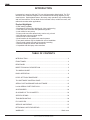
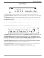
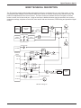
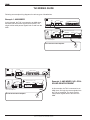
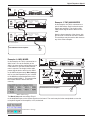
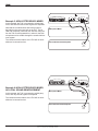
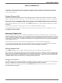
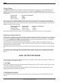
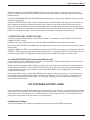
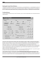
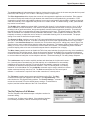
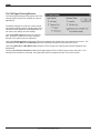
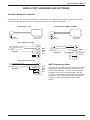
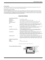
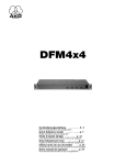
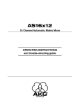
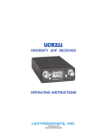
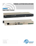
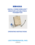
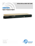
TH3 Digital Telephone Hybrid OPERATING INSTRUCTIONS and trouble-shooting guide LECTROSONICS, INC. Rio Rancho, NM INTRODUCTION Lectrosonics is proud to offer the TH3, our third generation digital hybrid. The TH3 interfaces with a standard telephone line to add teleconferencing capability to any sound system. Sophisticated featues, fast setup, easy operation, high sound quality and low cost make the TH3 an ideal choice for board rooms, conference rooms, talk radio and countless other applications. Product Highlights • DTMF dialing capability • Simultaneous 2-wire/4-wire bridging for 3-site conferencing • Three-way echo elimination with patented algorithm • Level meters for easy setup • Privacy mode can mute transmit only, receive only, or both • AGC enhances volume of weak signals • Wired remote control interface • Serial interface for integration with control systems • Front panel switches may be disabled for secure installation • Tape recorder output with relay for automatic recording • Automatic telephone answer and disconnect • Compatible with third-party echo cancellers TABLE OF CONTENTS INTRODUCTION .................................................................................................. 2 FRONT PANEL ..................................................................................................... 3 REAR PANEL ....................................................................................................... 4 BRIEF TECHNICAL DESCRIPTION ................................................................... 5 TH3 WIRING GUIDE ............................................................................................ 6 BASIC OPERATION ............................................................................................. 9 LEVEL SETTING PROCEDURE ....................................................................... 10 TH3 SOFTWARE CONTROL PANEL ................................................................ 11 SERIAL PORT HARDWARE AND SOFTWARE ............................................... 15 LecNet SERIAL PORT PROTOCOL .................................................................. 16 ACCESSORIES .................................................................................................. 22 GLOSSARY OF TH3 CONCEPTS ..................................................................... 22 SPECIFICATIONS .............................................................................................. 23 TROUBLESHOOTING ....................................................................................... 24 FCC NOTICES ................................................................................................... 25 SERVICE AND REPAIR ..................................................................................... 27 RETURNING UNITS FOR REPAIR ................................................................... 27 WARRANTY ......................................................................................... Back cover 2 Digital Telephone Hybrid FRONT PANEL LECTROSONICS, INC. RIO RANCHO, NM DIGITAL HYBRID U.S.A. CODEC TELEPHONE RX TX RX LEVEL TRIM LEVEL TX LEVEL LecNet ANTI-ECHO LecNet ANTI-ECHO RX LEVEL TX LEVEL The TX LEVEL control is used to set the proper amount of local signal, with the aid of the TX LEVEL meter. The TELEPHONE RX LEVEL control is used to set the proper telephone receive level, with the aid of the RX LEVEL meter. The CODEC RX LEVEL control is used to set the proper codec receive level, with the aid of the RX LEVEL meter. The CODEC TX TRIM control adjusts the level supplied to the CODEC OUT plug on the rear panel, accommodating level requirements of the codec. The LecNet ANTI-ECHO control adjusts the amount of echo reduction applied to a Lectrosonics automatic micro phone mixer (e.g. AM8 or AM16) via the LecNet expansion port. The LecNet ANTI-ECHO, RX LEVEL and TX LEVEL meters aid in setting system audio levels optimally. The TELEPHONE and CODEC interfaces include the following buttons and indicators. TELEPHONE CONNECT CODEC PRIVACY RECEIVE VOLUME UP DOWN CONNECT PRIVACY RECEIVE VOLUME UP SWITCHES DISABLED DOWN POWER The CONNECT button initiates or terminates a connection. The CONNECT led indicates an active connection. The telephone connect led flashes when the telephone line is ringing. The PRIVACY button mutes either the transmit signal, the received signal, or both, depending on the interface’s current privacy mode. When the privacy feature is engaged, the PRIVACY led flashes to indicate the current privacy mode, then glows steadily. Privacy may be disengaged by pressing the button again. For detailed information about privacy modes, please refer to the Privacy Feature topic in the chapter on BASIC OPERATION. The RECEIVE VOLUME buttons permit fine control of the receive volume during normal operation. Each button press alters the receive gain by 1 dB, and the control offers a range of -12 dB to +6dB (19 settings). The default setting of 0 dB may be restored by pressing both volume buttons simultaneously. The SWITCHES DISABLED led indicates that the interface buttons on the front panel have been disabled at the installer’s option. The wired remote controls and serial commands will operate normally. The POWER switch turns the TH3 on and off. The POWER led serves as a power status indicator. Rio Rancho, NM – USA 3 REAR PANEL PWR IN EXPANSION OUT (CH40) IN REMOTE CONTROLS LecNet TELEPHONE (RS232) 20 VAC CODEC The PWR IN jack must be attached to an appropriate power source, such as the included CH40 wall transformer. The EXPANSION OUT and EXPANSION IN jacks are used to attach the TH3 to other LecNet equipment (e.g. AM8 or AM16 mixers). The LecNet (RS232) jack may be connected to the serial port of a personal computer for configuration and testing. The REMOTE CONTROLS connectors may be wired to switches and leds for wired remote control of the TH3’s interface functions (connect, privacy, volume up and volume down). A pinout of the remote control ports is provided in the SPECIFICATIONS chapter. SUPPLEMENTARY ECHO CANCELLER AUX IN + – OUT + – OUTPUT LEVEL FINE LEVEL RECORD OUT RELAY + – COARSE LEVEL RX INSERT IN OUT + – + – TELEPHONE TX INSERT IN OUT + – + – CODEC IN + – SET LINE OUT + – MIC LINE The AUX interface provides line level, balanced or unbalanced main input and output from the TH3. Any signal imposed at AUX IN is transmitted to all connected interfaces, and any signal received from connected interfaces is available at AUX OUT, with as little of the transmitted signal as possible. The OUTPUT LEVEL control may be used to match the TH3’s AUX OUT signal with the level requirements of any attached equipment. The RECORD OUT interface contains a mix of transmitted and received signals, suitable for recording all parties in a conversation. The signal may be used balanced or unbalanced. The COARSE LEVEL switch and FINE LEVEL control easily accommodate the most common level requirements. When used as an unbalanced output, ground the negative output to ensure proper operation of the COARSE LEVEL switch. The relay contacts are closed when a connection is active, and open otherwise. The SUPPLEMENTARY ECHO CANCELLER jacks may be used to connect an external echo canceller for addi tional acoustic echo cancellation. Balanced operation is recommended, though unbalanced operation is possible. The CODEC jack provides line level, balanced or unbalanced input and output connections to an external four wire codec, as is commonly used in video conferencing applications. The CODEC RX LEVEL and CODEC TX TRIM front panel controls may be used to accommodate a wide range of audio levels, including the industry standard levels, -10 dBV and +4dBu. The TELEPHONE SET jack may be connected to an external telephone device. The device is connected to the telephone line only when the TH3 telephone interface is not connected. A standard telephone set, attached to this jack, may be used for dialing where DTMF dialing from the TH3 via the serial port is not practical or convenient. The TELEPHONE LINE jack connects to a standard telephone line. 4 Digital Telephone Hybrid BRIEF TECHNICAL DESCRIPTION The TH3 provides a high-quality, flexible and powerful interface to a telephone line, a 4-wire video codec, or both simultaneously with bridging. Each interface offers basic controls to connect, invoke privacy (selective mute), and perform fine adjustments to the receive volume. The basic controls are available from the front panel, the wired remote controls, and via the serial port. Using the serial port, additional features may be controlled, such as echo suppression settings, telephone receive AGC, auto answer and auto disconnect, DTMF dialing and specialized signal routing. PHONE INTERFACE LINE ECHO CANCEL "RX LEVEL" "TELEPHONE RX LEVEL" "CODEC TX TRIM" CODEC INTERFACE AGC ECHO SUPPRESSION RX BUS TX BUS ECHO SUPPRESSION "CODEC RX LEVEL" "OUTPUT LEVEL" "TX LEVEL" AUX PORT (SOFT) EXPANSION PORTS (SOFT) "AUX INPUT" "EXPANSION PORT" MAIN IN "TX LEVEL" "MAIN IN" "MIX MINUS IN" MIX- IN MAIN OUT (SOFT) MIX- OUT "MAIN OUT" "MIX MINUS OUT" "COARSE LEVEL" LINE/MIC SWITCH "FINE LEVEL" SIG IN RECORD OUT "LECNET ANTI-ECHO" SIG OUT log "LECNET ANTI-ECHO" SIG TOTAL TH3 Block Diagram Rio Rancho, NM – USA 5 TH3 WIRING GUIDE Following are example wiring diagrams for various types of installations. Example 1: AM8 MIXER PWR IN EXPANSION OUT (CH40) In this example, the TH3 is connected to an AM8 mixer, and both local and remote signals are amplified. The single LecNet cable passes signals both to and from the AM8. IN REMOTE CONTROLS LecNet TELEPHONE (RS232) 20 VAC CODEC TH3 LECTROSONICS, INC. PWR IN (CH40) 20 VAC EXPANSION M A S T E R S L A V E OUT IN LecNet (RS232) REMOTE LEVEL CONTROL MAIN OUT + – CH8 IN 1 2 3 4 + – DIR OUT AM8 Switch in MASTER position Sound Reinforcement Amplifier INPUT PWR IN EXPANSION OUT (CH40) IN REMOTE CONTROLS LecNet TELEPHONE (RS232) 20 VAC AUX CODEC IN + – OUT + – OUTPUT LEVEL TH3 LECTROSONICS, INC. PWR IN (CH40) 20 VAC EXPANSION M A S T E R S L A V E OUT IN LecNet (RS232) REMOTE LEVEL CONTROL MAIN OUT + – CH8 IN 1 2 3 4 DIR OUT AM8 Switch in MASTER position Sound Reinforcement Amplifier INPUT 6 + – Example 2: AM8 MIXER, NO LOCAL SOUND REINFORCEMENT In this example, the TH3 is connected to an AM8 mixer, and only the remote signals from the TH3 are amplified. The single LecNet cable passes signals both to and from the AM8. Digital Telephone Hybrid PWR IN EXPANSION OUT (CH40) IN REMOTE CONTROLS LecNet TELEPHONE (RS232) 20 VAC AUX CODEC IN OUT + – + – OUTPUT LEVEL TH3 LECTROSONICS, INC. PWR IN (CH40) 20 VAC EXPANSION M A S T E R S L A V E OUT IN REMOTE LEVEL CONTROL LecNet + – CH8 IN 1 2 3 4 In this example, the TH3 is connected to a pair of AM8 mixers. Both local and remote signals are amplified. The single LecNet cable passes signals both to and from the AM8. LECTROSONICS, INC. PWR IN 20 VAC DIR OUT + – AM8 Switch in SLAVE position (CH40) Example 3: TWO AM8 MIXERS MAIN OUT (RS232) EXPANSION M A S T E R S L A V E OUT IN LecNet REMOTE LEVEL CONTROL Note the interconnection of the mixers, with the last mixer in the chain set as the master. This technique may be used to add mixers to any of the other examples. MAIN OUT + – (RS232) CH8 IN 1 2 3 4 DIR OUT + – AM8 Switch in MASTER position Sound Reinforcement Amplifier INPUT Example 4: AM16 MIXER In this example, the TH3 is connected to an AM16 mixer. Due to the flexibility of the AM16, the same wiring configuration may be used whether or not local sound reinforce ment is required. The single LecNet cable passes signals both to and from the AM16. PWR IN IN REMOTE CONTROLS LecNet (RS232) 20 VAC TELEPHONE AUX CODEC IN OUTPUT LEVEL OUT + – + – TH3 AUDIO EXPANSIO PWR IN (PS60) In the AM16 software setup, Misc Settings tab, be sure the Expansion In port is linked to the NOM bus associated with the micro phones (usually NOM 1). This ensures that the LecNet anti-echo feature will work correctly. EXPANSION OUT (CH40) 16.5 VAC EXPANSION M A S S L T A E V R E OUT C UTPUTS IN LecNet LINE (RS232) 1 10 9 10 – + LINE OUTPUTS 9 8 – + 7 – + – + 6 5 – + – + 4 – + 3 – + 2 – + 1 – + MADE IN U.S.A. 0dB GAIN (LINE) PHANTOM POWER 16 15 14 13 12 11 10 9 OFF 8 7 6 5 ON AUDIO EXPANSIO 4 3 2 1 GAIN 6 5 6 – + 5 – + +30dB GAIN (ELECTRET) GAIN 4 3 4 – + 3 – + +50dB GAIN (DYNAMIC) GAIN 2 1 2 – + 1 – + AM16 Sound Reinforcement Amplifier INPUT AM16 NOM settings The Matrix Setup tab must assign “Exp In” to the amplified output, so the remote signals can be heard. The matrix may be further manipulated to route the microphone signals to the amplifier, or not, as desired. AM16 Matrix Settings Rio Rancho, NM – USA 7 REMOTE CONTROLS TELEPHONE CODEC AUX IN OUT + – + – OUTPUT LEVEL FINE LEVEL RECORD OUT RELAY + – COARSE LEVEL MIC LINE Example 5: NON-LECTROSONICS MIXER In this example, the TH3 is connected to a third-party mixer, and both local and remote signals are amplified. Note that the combined local and remote signal is derived from the record out jack on the TH3. This is valid and completely functional, but with this configura tion the TH3 must be powered on in order for the local microphones to be audible through the sound reinforce ment system. The LecNet anti-echo feature of the TH3 will not work without a Lectrosonics mixer. TH3 Microphone Mixer OUTPUT Sound Reinforcement Amplifier INPUT REMOTE CONTROLS TELEPHONE CODEC AUX IN + – OUT + – OUTPUT LEVEL FINE LEVEL RECORD OUT RELAY + – COARSE LEVEL MIC LINE Example 6: NON-LECTROSONICS MIXER, NO LOCAL SOUND REINFORCEMENT In this example, the TH3 is connected to a third party mixer, and only remote signals are amplified. TH3 Microphone Mixer OUTPUT The LecNet anti-echo feature of the TH3 will not work without a Lectrosonics mixer. Sound Reinforcement Amplifier INPUT 8 Digital Telephone Hybrid BASIC OPERATION This chapter describes the TH3’s most essential user functions. The word “interface” is used here to distinguish between the controls associated with the telephone (“telephone interface”) and those associated with the 4-wire codec (“codec interface”). Placing a Telephone Call Telephone calls may be initiated from the TH3’s front panel, from a wired remote control, or from a PC or control system connected via the TH3’s serial port. The TH3’s DTMF dialer may be used only from a PC or control system. The simplest way to place a call is to attach a standard telephone to the Telephone Set jack. Dial the call with the telephone, then press the CONNECT button for the telephone interface. When the TH3 connects, it automatically disconnects the telephone set from the line. The CONNECT led will turn on and remain illuminated for the duration of the call. If the TH3 does not remain connected, please refer to the TROUBLESHOOTING chapter. For information about using the TH3 software control panel to dial a call, please refer to the chapter on the TH3 SOFTWARE CONTROL PANEL. Answering a Telephone Call Upon receipt of an incoming call, the CONNECT led flashes and, optionally, a beeping sound is sent to the audio outputs to indicate a ringing condition. By default, the TH3 will not answer telephone calls automatically. To manually answer an incoming telephone call, press the CONNECT button for the telephone interface on either the front panel, the wired remote control, or the TH3 software control panel. The CONNECT led will turn on and remain illuminated for the duration of the call. If the TH3 does not remain connected after answering, please refer to the Troubleshooting chapter. For information about answering the phone from the TH3 software control panel or configuring the TH3 to answer incoming calls automatically, please refer to the chapter on the TH3 Software Control Panel. Ending a Telephone Call The CONNECT button acts as a toggle. Pressing it while a call is in progress will disconnect the call. The TH3 offers an automatic disconnect feature which is disabled by default. On telephone networks supporting this feature, the TH3 can automatically disconnect when the other party disconnects. This feature is not compatible with some PBX systems and the call waiting feature on some telephone networks. Please refer to the TH3 SOFTWARE CONTROL PANEL chapter for information on enabling automatic disconnect. Using the 4-wire Codec The codec interface works nearly identically to the telephone interface, except that it is simpler. The codec interface requires no dialing, and no automatic answer or automatic disconnect features are offered. To connect or disconnect, simply press the codec CONNECT button on either the front panel, the wired remote, or the TH3 software control panel. Rio Rancho, NM – USA 9 Privacy Feature The PRIVACY buttons mute the respective interface’s transmit signal, receive signal, or both, depending on the interface’s current privacy mode. As the privacy feature is engaged, the PRIVACY led flashes a confirmation to indicate the current privacy mode, then glows steadily. The privacy modes and confirmation flashes are listed in the following table. Privacy mode Mute TX only Mute RX only Mute TX and RX Privacy led confirmation 1 flash 2 flashes 3 flashes Each interface’s current privacy mode may be selected from the front panel or wired remote control via special button combinations. To select a specific privacy mode, simply hold down one or more RECEIVE VOLUME buttons while pressing the PRIVACY button. The privacy mode is selected according to the following table. The privacy led flashes to confirm the selected mode. Button Combination UP+PRIVACY DOWN+PRIVACY UP+DOWN+PRIVACY Privacy Mode Mute TX only Mute RX only Mute TX and RX Privacy led confirmation 1 flash 2 flashes 3 flashes Each interface has its own privacy mode. The selected privacy modes persist when the TH3 is powered off. Adjusting the Receive Volume When the TH3 is installed, all levels are adjusted for good performance. Sometimes, in the course of a conversation, it is desirable to make small changes to the receive volume to compensate for varying conditions. For this purpose, the TH3 offers RECEIVE VOLUME up and down buttons on the front panel and the wired remote. The software control panel offers a slider that performs the same function. The receive volume up and down buttons provide a range from -12 dB to +6 dB in 1 dB steps (for a total of 19 possible settings). The default setting is +0 dB. The receive volume may be reset to +0 dB directly by pressing the up and down volume buttons together. Each interface has its own receive volume. The selected receive volume settings persist when the TH3 is powered off. If you find you are constantly adjusting the telephone receive volume, you may wish to consider increasing the Rx AGC setting. Refer to the chapter on the TH3 SOFTWARE CONTROL PANEL for more information on the AGC feature. LEVEL SETTING PROCEDURE In order to obtain the best performance from the TH3, it is necessary to set all audio levels properly. Thanks to the built-in metering, the procedure is simple. 1. TX LEVEL Have someone speak normally into a local microphone and adjust the TX LEVEL control so that the red led on the TX LEVEL meter lights only occasionally. If more than one local microphone is installed, please verify that all microphone levels are approximately equal, applying any necessary corrections at the mixer. 2. TELEPHONE RX LEVEL If the telephone line interface portion of the TH3 will be used, it is necessary to set the TELEPHONE RX LEVEL control. 10 Digital Telephone Hybrid Establish a telephone call (the BASIC OPERATION chapter tells how to do this), preferably to an actual person, group or location to which this TH3 will typically connect. If this is not possible, a call may be placed to a recorded message service. Press both TELEPHONE RECEIVE VOLUME buttons simultaneously to reset the user telephone receive volume to its default setting (0 dB). Adjust the TELEPHONE RX LEVEL control so that the red led on the RX LEVEL meter lights only occasionally. An active telephone connection will also be required for step 4, below, so you might not want to disconnect just yet. Note: It is common for the dial tone and other signaling tones to be louder than normal speech levels. Particularly if the receive AGC is not used, the dial tone may read off the scale of the RX LEVEL meter when the TELEPHONE RX LEVEL is set correctly for speech. This is normal and does not require a reduction in the level setting. 3. CODEC RX LEVEL, CODEC TX LEVEL If the four wire codec interface portion of the TH3 will be used, it is necessary to set the CODEC RX LEVEL and CODEC TX LEVEL controls. Establish a connection using the four wire codec (the BASIC OPERATION chapter tells how to do this). Press both CODEC RECEIVE VOLUME buttons simultaneously to reset the user codec receive volume to its default setting (0 dB). Adjust the CODEC RX LEVEL control so that the red led on the RX LEVEL meter lights only occasionally. Adjust the CODEC TX TRIM control for proper level as required by the codec. If the codec provides no level indication, in most cases setting the CODEC TX TRIM approximately the same as the CODEC RX LEVEL control will suffice. 4. LecNet ANTI-ECHO [with Lectrosonics Mixers only] If your installation uses a Lectrosonics mixer which is connected via the TH3’s LecNet Expansion Out jack, use this procedure to set the LecNet ANTI-ECHO control. With a connection established (either telephone or codec), have someone speak normally into a local microphone and take note of the behavior of the LecNet ANTI-ECHO meter. Next, have the remote party speak, and adjust the LecNet ANTI-ECHO control until the deflection of the LecNet ANTI-ECHO meter is approximately equal to that caused by the local signal. Note: Exactly where to set the LecNet ANTI-ECHO control is largely a matter of preference. If it is set too low, the remote party may hear objectionable echoes immediately after speaking. If it is set too high, local speakers may have difficulty interrupting the remote speaker. In most cases, setting the control for equal meter deflection, as above, yields excellent results. TH3 SOFTWARE CONTROL PANEL Some of the TH3’s more advanced features may be accessed only via the serial port. A convenient software “control panel” for the TH3 is included in the LecNet Master Pro software package. The TH3 software may be run alone as a demonstration of the TH3’s features, or via LecNet Master Pro for live control of a TH3. The TH3 software control panel permits easy access to all TH3 features, as described below. Installing the Software To install LecNet Master Pro, insert the LecNet Master Pro disk and run SETUP.EXE from the disk. Rio Rancho, NM – USA 11 Starting the Control Panel Software To start the TH3 software control panel, it is first necessary to run LecNet Master Pro. If LecNet Master Pro does not immediately detect the TH3, check to make sure that the LecNet PC cable is connected from the PC’s COM port to the TH3. Check also that LecNet Master Pro is accessing the correct COM port. Once the TH3 is properly detected, the TH3 software control panel can be started by choosing Select Device from LecNet Master Pro’s Devices menu. The Main Window The main window provides access to most TH3 features, some of which are duplicated on the front panel and wired remote controls. The title bar of the main window includes the word “Demonstration” when the software control panel was invoked directly, as a demonstration of the TH3’s features and control panel operation. When the software control panel is or has been actively connected to a TH3, as when invoked via LecNet Master Pro, the TH3’s LecNet device address appears in the title bar. This is especially useful if more than one TH3 is being configured simultaneously. In the upper right-hand corner of the window is the LecNet Status frame, which indicates whether the serial link to the TH3 is currently active. A status of on means the TH3 is connected, the control panel is active, and the settings shown correspond with the TH3’s current configuration. [Note: The connection will be active only when the TH3 software control panel application is active.] Below the status frame is the Tone Pad, which may be used to generate DTMF dialing tones. If you prefer to type in a number to be dialed automatically, see the Dial... command under the TH3 menu. The two largest frames in the main window are the Telephone and Codec frames, which control the TH3’s tele phone and codec interfaces. Each frame is equipped with connect and privacy buttons and indicators, which duplicate the corresponding front panel controls. The privacy indicator does not flash the current privacy mode, as it does on the front panel, however the current privacy mode is displayed, and may be selected via the radio buttons. 12 Digital Telephone Hybrid The receive volume is implemented as a slider but it selects the receive volume in the same way that the front panel buttons do, with a range of -12 to +6 dB in 1 dB steps (a total of 19 positions). The Echo Suppression sliders choose the amount of echo suppression applied to each interface. Echo suppres sion refers to the dynamic trade-off of gain between the transmit and receive paths during conversation. Echo suppression reduces echo and feedback problems, but too much may interfere with the ability of parties to interrupt each other naturally. Echo suppression may be set from 12 dB to 24 dB. The default setting, 18 dB, yields satisfac tory results in most cases. The Rx AGC slider enables an optional AGC (“Automatic Gain Control”) in the telephone receiver. Up to 12 dB of AGC is available (in 3 dB increments). AGC tends to equalize disparate volume levels, so that poor connections sound as loud as good connections, and gentle speakers sound as loud as aggressive speakers. The trade-off is that AGC brings with it a corresponding increase in background noise level. The default setting is 0 dB of AGC, which is ideal when line conditions remain predictable and favorable. Under variable line conditions, where it is frequently necessary to adjust the receive volume for comfortable listening, AGC is recommended. The proper setting to use must be determined experimentally. The Answer On Ring checkbox controls the TH3’s automatic telephone answering feature. If the box is unchecked, the TH3 will not answer the phone. If the box is checked, the TH3 will count rings and answer on the ring number specified. If the Auto Disconnect box is checked, the TH3 monitors the line for a “calling party control” signal. This signal is sent by some central offices when the other party disconnects. This feature might not work reliably if “call waiting” is in use, or if the TH3 is connected to a PBX or other line simulator. The Audible Ring Chime checkbox permits a beeping noise to be sent to the audio outputs when the telephone line is ringing. The Misc. frame contains controls to disable the TH3’s front panel switches (for physical security of the installation), and to adjust the TH3’s dialing speed. When the front panel switches are disabled, the recessed level adjustment controls still function, and all remote controls will continue to operate. The dialing speed parameter is provided only to accommodate unusually fast or slow telephone switches. The default setting of 4 is nearly always adequate. The LecNet menu may be used to explicitly activate and deactivate the LecNet serial connec tion. Generally these commands are not used explicitly, as LecNet Master Pro automatically establishes the connection, and the TH3 control panel automatically suspends or closes the connection as needed for sharing with other software. If the TH3 control panel is run directly instead of via LecNet Master Pro, the LecNet On command may be used to switch from demon stration mode and actively connect a TH3. The Exit command quits the TH3 control panel software. A confirmation is required if the LecNet connection is currently active. The TH3 menu is used to access some special features of the TH3. The Dial... command invokes the Dial Telephone Call window. The Signal Routing... com mand invokes the TH3 Signal Routing window. The Factory Settings... command reverts the connected TH3 to the default factory settings. A confirmation is required, and the LecNet address of the TH3 is not affected. The Dial Telephone Call Window The Dial Telephone Call window accepts a telephone number for automatic dialing. A maximum of 16 digits may be dialed. If the telephone interface is not already connected, it will be connected prior to dialing. Rio Rancho, NM – USA 13 The TH3 Signal Routing Window The TH3 Signal Routing window permits the TH3’s internal signal routing to be modified for unusual applications. The default settings are as shown, with all inputs and outputs enabled, and the supplementary echo canceller inserts bypassed. Most applications do not require any change to these settings. Unchecking AUX Input mutes the TH3’s AUX IN port. AUX OUT continues to function normally, and the TH3’s other inputs are unaffected. Unchecking Expansion Port prevents the TH3 from accepting input signals from any expansion port source. The checkboxes below (Main In and Mix Minus In) offer individual muting of the expansion port inputs. Unchecking Main Out or Mix Minus Out prevents the TH3’s output from reaching the indicated expansion port destinations. Checking Use External Canceller enables the Supplementary Echo Canceller inserts on the rear panel. If no external echo canceller is connected, the signal paths will be incomplete and the TH3 will not function. 14 Digital Telephone Hybrid SERIAL PORT HARDWARE AND SOFTWARE Serial Port Hardware Connection The serial port on the TH3 is a minimal RS-232 implementation. The figure shows the wiring diagram to accommo date interconnection with either a 9- or a 25-pin serial port on a PC or other serial device. LecNet Device to PC S R T 3.5MM Stereo Plug LecNet Device to AMX or Crestron S R T 9 or 25 Pin Female D-Subminiature 9 Pin Female D-Subminiature 3.5MM Stereo Plug Wiring Diagram, 9 Pin D-Sub CD RX TX DTR Gnd DSR RTS CTS RI 1 2 3 4 5 6 7 8 9 RX TX Sig Gnd Chassis Gnd RTS CTS DSR DTR 3 2 7 1 4 5 6 20 N/C Tip Ring Sleeve LecNet Device Transmit LecNet Device Receive Gnd LecNet Port N/C N/C Host Serial Port (PC) LecNet Device Transmit LecNet Device Receive Gnd Tip Ring Sleeve LecNet Port RXD TXD N/C Gnd N/C N/C N/C N/C 1 2 3 4 5 6 7 8 9 AMX or Crestron Port Wiring Diagram, 25 Pin D-Sub Tip Ring Sleeve LecNet Device Transmit LecNet Device Receive Gnd LecNet Port AMX Programming Notes Host Serial Port (PC) If you are using an AMX system to control your LecNet equipment, you’ll want to purchase the Lectrosonics PT3 Protocol Translator. The PT3 connects between the AMX bus and any LecNet equipment. With the PT3, the LecNet equipment looks just like native AMX equipment. The PT3 is the fastest and most produc tive way to control LecNet devices with an AMX system. Rio Rancho, NM – USA 15 LecNet SERIAL PORT PROTOCOL All LecNet devices use a modification of the typical one-to-one connection between two RS-232 compatible devices. LecNet devices have both an RS-232 transmitter and receiver section. The transmitter section is “tri-stated”, or placed in a high impedance mode, until the particular device is addressed. To facilitate the simple parallel connection of multiple devices on a single RS-232 port, an addressing scheme is employed to route commands from the host to the proper LecNet device. When a device receives its address from the host computer, it temporarily turns on its RS 232 transmitter long enough to send whatever data is requested by the host. In this way, multiple devices may drive a single transmit signal back to the host, because only the addressed device will turn on its transmitter. Valid address values are 128-254 (80 hex-FE hex). Because a LecNet device will interpret any single data byte whose value is greater than 127 as an address, single byte data (as opposed to addresses) sent from the host must be in the range of 0-127. If a data value needs to be sent from the host that exceeds 127, the host must format two bytes of output such that the first byte is the lower 7 bits of the 8 bit value, and the second byte is 1 if the MSB of the data byte is 1, or 0 if the MSB of the data byte is 0. All interchange of commands and data with any LecNet device is done numerically rather than ASCII. The only exception to this is the return data on the Get Device Name command (see command description below). Each LecNet command must be preceded by the address of the device to be controlled. If a device with the requested address exists on the system, it will respond by sending a 0 (0 hex, not ASCII) back to the host. Thus, each inter change with a LecNet device follows this pattern: 1) Host sends device address as a single byte. 2) Host receives byte of 0 hex from the LecNet device as acknowledgment. 3) Host sends command (1 byte) to the LecNet device. 4) Host and LecNet device exchange data based on particular command sent. Note that some LecNet commands cause LecNet devices to return an additional acknowledgment byte of data to confirm the end of a transaction. This is most typical of commands that cause the LecNet device to be busy for more than a few milliseconds processing the command. The additional acknowledgment byte lets the host know that the LecNet device is no longer busy and can receive more commands. If a command does return an additional acknowl edgment byte, this will be explicitly stated in the command description. As an example of a specific interchange between a host and a TH3, the following general procedure would be used to get a name string back from the TH3. Set up the communications parameters of the device which will be the host. The correct parameters for all LecNet devices are 9600 baud, no parity, 8 data bits, 1 stop bit. This need only be done once when the host is initialized. 1) Host sends the device address of the TH3 (133 or 85 hex, by default). 2) Host receives byte of 0 hex from the TH3 as acknowledgment. 3) Host sends command 1 hex (1 byte) to the TH3 to get the name data. 4) The TH3 sends to the host 4 bytes. The first byte is 3 hex, which is the number of bytes in the TH3’s name string. The TH3 will then send the ASCII characters “T”, “H”, and “3” to the host. The following section is a listing of available TH3 commands. The word “Host” in the command descriptions means the IBM PC or compatible, AMX controller, or Crestron controller to which the TH3 is connected. All numbers are decimal unless otherwise specified. 16 Digital Telephone Hybrid General Device Commands Get Device Name - Causes the TH3 to send its “name” string back. The first data byte is the length of the name string, and the rest of the data bytes are the device name. Host sends command - 1 Host receives data bytes: Byte 1 is the length of the name string (3 for the TH3), bytes 2 thru 4 are the ASCII values for “TH3”. Set Device Address - Changes the TH3’s device address. The new setting persists when the TH3 is powered off. Even when the TH3 is restored to factory settings, the device address is not changed. Host sends command - 2 Host sends 1 byte representing the new device address, 128-254. Restore Factory Settings - Causes the TH3 to revert to its original factory settings. All settings are affected with the exception of the LecNet device address. This may be changed only by issuing the Set Device Address command, above. Host sends command - 3 Get Firmware Version - Causes the TH3 to send to the host the version number of the current firmware (times ten). For example, Version 1.0 software would be returned as byte value 10 (decimal). Host sends command - 25 Host receives data byte: firmware version. Basic Operation Commands Set Phone Connect - Causes the TH3 to connect or disconnect the telephone interface. Host sends command - 30 Host sends byte: 0 to disconnect, 1 to connect Get Phone Connect - Retrieves connect status of telephone interface. Host sends command - 31 Host receives data byte: 0 if disconnected, 1 if connected Set Phone Privacy - Engages or disengages telephone privacy feature. This command has no effect if the telephone interface is not connected. Host sends command - 32 Host sends byte: 0 to disengage privacy feature, 1 to engage Get Phone Privacy - Retrieves privacy status of telephone interface. Host sends command - 33 Host receives data byte: 0 if disengaged, 1 if engaged Set Codec Connect - Causes the TH3 to connect or disconnect the codec interface. Host sends command - 34 Host sends byte: 0 to disconnect, 1 to connect Get Codec Connect - Retrieves connect status of codec interface. Host sends command - 35 Host receives data byte: 0 if disconnected, 1 if connected Rio Rancho, NM – USA 17 Set Codec Privacy - Engages or disengages codec privacy feature. This command has no effect if the codec interface is not connected. Host sends command - 36 Host sends byte: 0 to disengage privacy feature, 1 to engage Get Codec Privacy - Retrieves privacy status of codec interface. Host sends command - 37 Host receives data byte: 0 if disengaged, 1 if engaged DTMF Tone Commands Send DTMF Tone - Causes the TH3 to dial a single DTMF digit. The telephone connect status is not affected, and the tone is generated regardless of telephone connect status. Host sends command - 40 Host sends ASCII byte representing DTMF tone Valid values are the ASCII numerals 0-9 and the characters A-D, * and #. Dial Telephone Number - Causes the TH3 to dial a telephone call whose number is supplied as a string. The telephone interface is automatically connected, if necessary, before dialing begins. Host sends command - 41 Host sends ASCII string representing telephone number Valid values are the ASCII numerals 0-9 and the characters A-D, * and #. A comma may be used to insert a one second delay. The ! character may be used to generate a “flash” signal. Any unrecognized character is ignored (i.e. dashes and parentheses are acceptable). The string must be terminated by a carriage return (decimal 13). The string’s length must not exceed 16 characters plus the carriage return. Setup Commands Set Panel Disable - Disables or enables the front panel switches on the TH3. Host sends command - 50 Host sends byte: 0 to enable panel, 1 to disable Get Panel Disable - Retrieves the enabled or disabled status of the TH3 front panel switches. Host sends command - 51 Host receives data byte: 0 for enabled, 1 for disabled Set Dial Speed - Determines the TH3’s DTMF tone duration and automatic dialing speed. Host sends command - 52 Host sends byte in range 1-10: 1 is the fastest, 10 is the slowest, 4 is the default speed. Get Dial Speed - Retrieves the current dialing speed. Host sends command - 53 Host receives data byte in range 1-10: 1 is the fastest, 10 is the slowest, 4 is the default speed. Set Auto Disconnect - Turns the TH3’s automatic disconnect feature on or off. Host sends command - 54 Host sends byte: 0 to disable the feature, 1 to enable it Get Auto Disconnect - Retrieves the status of the TH3’s automatic disconnect feature. Host sends command - 55 Host receives data byte: 0 if the feature is disabled, 1 if it is enabled 18 Digital Telephone Hybrid Set Auto Answer - Configures the TH3’s automatic telephone answering feature. Host sends command - 56 Host sends byte: 0 to disable the feature, 1-10 to specify a ring count on which to answer the telephone. Get Auto Answer - Retrieves the current status of the TH3’s automatic telephone answering feature. Host sends command - 57 Host receives data byte: 0 if disabled, 1-10 specifies ring count on which TH3 answers. Set Phone Rx AGC - Configures the telephone receive AGC. Host sends command - 58 Host sends byte: 0: AGC off, 1: 3 dB, 2: 6 dB, 3: 9 dB, 4: 12 dB Get Phone Rx AGC - Retrieves the current configuration of the telephone receive AGC. Host sends command - 59 Host receives data byte: 0: AGC off, 1: 3 dB, 2: 6 dB, 3: 9 dB, 4: 12 dB Set Expansion Input Routing - Controls TH3 expansion port input signal routing. Host sends command - 60 Host sends byte: 0: both exp inputs off, 1: mix minus input on, 2: main input on, 3: both exp inputs on Get Expansion Input Routing - Retrieves the current TH3 expansion port input signal routing. Host sends command - 61 Host receives data byte: 0: both exp inputs off, 1: mix minus input on, 2: main input on, 3: both exp inputs on Set Expansion Output Routing - Controls TH3 expansion port output signal routing. Host sends command - 62 Host sends byte: 0: both exp outputs off, 1: mix minus output on, 2: main output on, 3: both exp outputs on Get Expansion Output Routing - Retrieves the current TH3 expansion port output signal routing. Host sends command - 63 Host receives data byte: 0: both exp outputs off, 1: mix minus output on, 2: main output on, 3: both exp outputs on Set Input Signal Routing - Controls TH3 input signal routing. Host sends command - 64 Host sends byte: 0: all inputs off, 1: expansion port inputs on (refer to Set Expansion Input Routing com mand, above), 2: aux input on, 3: expansion port and aux inputs on Get Input Signal Routing - Retrieves TH3 input signal routing. Host sends command - 65 Host receives data byte: 0: all inputs off, 1: expansion port inputs on (refer to Set Expansion Input Routing command), 2: aux input on, 3: expansion port and aux inputs on Set Supplementary Canceller Insert - Enables or disables supplementary echo canceller inserts. Host sends command - 66 Host sends byte: 0 to bypass insert, 1 to enable insert Get Supplementary Canceller Insert - Retrieves status of echo canceller inserts. Host sends command - 67 Host receives data byte: 0 if insert is bypassed, 1 if insert is enabled Set Audible Ring Chime - Enables or disables the audible ring chime feature. Host sends command - 68 Host sends byte: 0 to disable the feature, 1 to enable it Rio Rancho, NM – USA 19 Get Audible Ring Chime - Retrieves status of audible ring chime feature. Host sends command - 69 Host receives data byte: 0 if feature is disabled, 1 if enabled Set Phone Echo Suppression - Selects amount of echo suppression applied to telephone interface. Host sends command - 70 Host sends byte in range 36-72: 36 represents 12 dB of suppression, 72 represents 24 dB of suppression. Any amount in between may be selected for continuous adjustment between 12 and 24 dB in 1/3 dB incre ments. Get Phone Echo Suppression - Retrieves amount of echo suppression applied to telephone interface. Host sends command - 71 Host receives data byte: 36 represents 12 dB of suppression, 72 represents 24 dB of suppression. Any amount in between may be selected for continuous adjustment between 12 and 24 dB in 1/3 dB increments. Set Phone Rx Atten - Performs fine adjustment of telephone receive volume. Host sends command - 72 Host sends byte in range 0-54, 126 or 127: 0 represents +6 dB, 18 represents 0 dB, 54 represents -12 dB. All values in between 0 and 54 are valid, representing 1/3 dB increments. A value of 126 causes the receive volume to decrease 1 dB. A value of 127 causes the receive volume to increase 1 dB. Get Phone Rx Atten - Retrieves current fine adjustment of telephone receive volume. Host sends command - 73 Host receives byte in range 0-54: 0 represents +6 dB, 18 represents 0 dB, 54 represents -12 dB. All values in between are valid, representing 1/3 dB increments. Set Phone Privacy Mode - Selects privacy mode for telephone interface. Host sends command - 74 Host sends byte: 1: mute tx only, 2: mute rx only, 3: mute both Get Phone Privacy Mode - Retrieves privacy mode for telephone interface. Host sends command - 75 Host receives data byte: 1: mute tx only, 2: mute rx only, 3: mute both Set Codec Echo Suppression - Selects amount of echo suppression applied to codec interface. Host sends command - 80 Host sends byte in range 36-72: 36 represents 12 dB of suppression, 72 represents 24 dB of suppression. Any amount in between may be selected for continuous adjustment between 12 and 24 dB in 1/3 dB incre ments. Get Codec Echo Suppression - Retrieves amount of echo suppression applied to codec interface. Host sends command - 81 Host receives data byte: 36 represents 12 dB of suppression, 72 represents 24 dB of suppression. Any amount in between may be selected for continuous adjustment between 12 and 24 dB in 1/3 dB increments. 20 Digital Telephone Hybrid Set Codec Rx Atten - Performs fine adjustment of codec receive volume. Host sends command - 82 Host sends byte in range 0-54, 126 or 127: 0 represents +6 dB, 18 represents 0 dB, 54 represents -12 dB. All values in between 0 and 54 are valid, representing 1/3 dB increments. A value of 126 causes the receive volume to decrease 1 dB. A value of 127 causes the receive volume to increase 1 dB. Get Codec Rx Atten - Retrieves current fine adjustment of codec receive volume. Host sends command - 83 Host receives byte in range 0-54: 0 represents +6 dB, 18 represents 0 dB, 54 represents -12 dB. All values in between are valid, representing 1/3 dB increments. Set Codec Privacy Mode - Selects privacy mode for codec interface. Host sends command - 84 Host sends byte: 1: mute tx only, 2: mute rx only, 3: mute both Get Codec Privacy Mode - Retrieves privacy mode for codec interface. Host sends command - 85 Host receives data byte: 1: mute tx only, 2: mute rx only, 3: mute both Monitoring Commands The following commands are intended for convenient fast monitoring of TH3 status from control systems. Get Quick Settings - Retrieves information about current TH3 status that may change at any time. Host sends command - 100 Host receives 3 data bytes: Byte 1: connect status, privacy status and privacy mode for both interfaces, expressed as a bitmap. The low order nibble contains telephone information, and the upper nibble contains codec informa tion. Within each nibble, bit 0 (the LSB) is the connect status, bit 1 is the privacy status, and bits 2 and 3 contain the privacy mode. Byte 2: telephone receive attenuation (see Get Phone Rx Atten, above) Byte 3: codec receive attenuation (see Get Codec Rx Atten, above) Get Full Settings - Retrieves information about current TH3 status that does not change asynchronously (except signal routing information). Host sends command - 101 Host receives 4 data bytes: Byte 1: telephone echo suppression (see Get Phone Echo Suppression, above) Byte 2: codec echo suppression (see Get Codec Echo Suppression, above) Byte 3: upper nibble: dial speed (see Get Dial Speed), lower nibble: auto answer setting (see Get Auto Answer). Byte 4: bit 4-7 (upper nibble) rx agc setting (see Get Phone Rx AGC, above), bit 2 audible ring chime status, bit 1 auto disconnect enable status, bit 0 (LSB) panel switch disable status Rio Rancho, NM – USA 21 ACCESSORIES Standard 21552 21553 21554 21551 21529 40024 LNETWIN M-TH3 35679 21580 15 ft. telephone cable with RJ-11 connectors 9-pin male D-sub connector Shell for 9-pin D-sub connector 12" mini-DIN LecNet expansion cable 9-pin D-sub to stereo mini plug LecNet PC cable CH-40 wall transformer LecNet software TH3 instruction manual mini straight slot screwdriver 5-pin depluggable terminal block Optional RCW-TEL RCW-DESK 21592 wall plate remote control unit table top remote control unit 24" mini-DIN LecNet expansion cable GLOSSARY OF TH3 CONCEPTS AGC Automatic Gain Control. As used in the TH3, a circuit that compresses telephone receive volume levels, so that weaker signals sound almost as loud as stronger ones. The trade-off is that background noise levels are also increased in proportion to the AGC setting. Bridging Bridging refers to the interconnection of two otherwise separate interfaces. The TH3 not only has the ability to communicate via telephone and to communicate via the 4-wire codec interface simultaneously, it has the ability to bridge the interfaces, such that codec signals are retransmitted over the telephone and vice versa. Echo Suppression A process whereby the gains of the transmit and receive paths are altered during a conversation, so that the path that is least active receives the least gain. This has the effect of reducing both feedback and acoustic echo. The TH3 uses a patented echo suppression algorithm for smooth, transparent operation. Hybrid A device that converts a two-wire interface (e.g. the telephone network) to a four-wire interface, by isolating the transmit and receive paths. The TH3 is a hybrid, with many special features. Interface As used in this manual, “interface” is used to distinguish groups of controls associated with the telephone and the 4 wire codec. (e.g. “Press the CONNECT button for the telephone interface.”) LecNet Anti-Echo This is a special echo reduction feature available only when the TH3 is used with a Lectrosonics mixer. It allows the TH3’s receive signal to participate in the automatic microphone mixing algorithm, so that the local microphones receive less gain while the remote party is speaking. Line Echo Canceller The portion of a hybrid that removes as much as possible of the reflected transmitted signal from the receive path. The job of the line echo canceller is made difficult by the highly variable conditions encountered on telephone lines. The TH3 uses a specialized DSP chip for this purpose. 22 Digital Telephone Hybrid Privacy Modes The privacy switch on the TH3 can do three different things, based on the interface’s current privacy mode. The three modes are, “mute tx only”, “mute rx only”, and “mute tx and rx”. Supplementary Echo Canceller The term “supplementary echo canceller” refers to any third-party acoustic echo canceller. Such a device may be used to supplement the existing echo cancelling abilities of the TH3. Typically, an additional 5 dB of echo cancella tion may be achieved. In installations where very large amounts of microphone gain are required, a supplementary echo canceller might significantly improve system performance. SPECIFICATIONS Technical Specifications Power Input Expansion Jacks 300 mA (10W max.) at 20VAC LecNet compatible, 8-pin mini-DIN, max. level +18dBu RS-232 Port Wired Remote Controls Aux LecNet compatible, stereo mini phone jack, 9600 baud, 8 bits, no parity, 1 stop bit DB9F connector (see next section for pinout); max. LED current per pin 7mA 5-pin depluggable terminal block connector; electronically balanced output; nom. output range -10 dBu to +4 dBu; max. output level +10 dBu; output impedance 200 ohms balanced, 100 ohms unbalanced; nom. input range -10 dBu to +4 dBu; max. input level +10 dBu; input impedance 20K ohms balanced, 10K ohms unbalanced 5-pin depluggable terminal block connector; electronically balanced output; max. mic level -20dBu; max. line level +4dBu; nom. impedance 600 ohms balanced, 300 ohms unbalanced; tape relay max. current 0.25A; two 5-pin depluggable terminal block connectors; electronically balanced outputs; nom. levels +4 dBu; input impedance 20K ohms balanced, 10K ohms unbalanced; output impedance 200 ohms balanced, 100 ohms unbalanced Record Out Supplementary Echo Canceller Codec Interface Telephone Interface 5-pin depluggable terminal block connector; electronically balanced output; nom. output range -10 dBu to +4 dBu; max. output level +10 dBu; output impedance 200 ohms balanced, 100 ohms unbalanced; nom. input range -10 dBu to +4 dBu; max. input level +10 dBu; input impedance 20K ohms balanced, 10K ohms unbalanced; echo suppression 12 dB to 24 dB in 1 dB steps; user receive volume -12dB to +6dB in 1 dB steps RJ11 modular connectors; compliant with FCC Part 68; impedance 600 ohms; auto answer on ring count 1-10 if enabled; disconnect on calling party control signal if enabled; echo suppression 12 dB to 24 dB in 1 dB steps; frequency response 300 Hz to 3500 Hz, +- 3dB; THD (250 Hz to 3.3 KHz) less than .2%; user receive volume -12dB to +6dB in 1 dB steps Physical Characteristics Weight Dimensions 4 lb. 19" wide x 1.75" high x 8" deep (specifications subject to change without notice) Pinout for Wired Remote Controls VOLUME DOWN VOLUME UP 5 4 9 3 8 2 7 1 6 PRIVACY CONNECT PRIVACY LED CONNECT LED Rio Rancho, NM – USA 23 TROUBLESHOOTING The following are general guidelines and initial suggestions. If a problem persists, please refer to the section, SERVICE AND REPAIR. Telephone interface won’t stay connected. The automatic disconnect feature is disconnecting the line inappropriately. Ensure that the telephone line is connected to the telephone line jack and not the telephone set jack. Ensure that the line is live by connecting a telephone to the telephone set jack and getting a dial tone. If you are connecting via a PBX or have call waiting enabled, it may be necessary to disable the automatic disconnect feature via the software control panel. Software control panel spontane ously disconnects from LecNet All LecNet software must share the serial port so that multiple software control panels may be operated simultaneously. The TH3 software will close the serial port temporarily whenever the software is minimized or inactive. It will reconnect when reactivated. I can hear the remote parties on both the telephone and codec interfaces, but they are having trouble hearing each other. It is possible to set receive levels too low and then compensate with more amplification. You will hear the remote parties but they will not hear each other properly. Also, the echo suppression will not work optimally in this situation. To correct, use the meters to set the receive levels of both the telephone and codec interfaces, as described in the LEVEL SETTING PROCEDURE. The TH3 appears to connect but I’m not getting any sound. Verify that privacy is not engaged (privacy led is off), and the interface is connected (connect led is on). Make sure the potentiometers on the front panel are not turned all the way down. Check all interconnects and mixer settings. If the telephone interface is to be used, verify that an external telephone, connected to the telephone set jack, is able to raise a dial tone when the TH3 telephone interface is not connected. If the meters are moving, check for problems with the local sound reinforcement system. With the software control panel, verify that the supplementary echo cancel ler inserts are not active and that all inputs and outputs are enabled. If all else fails, try restoring the TH3 to factory settings, as described at the end of this section. I have trouble interrupting the other party, or the other party has trouble interrupting me. This problem occurs when the transmit and receive levels are not set equitably, or when the LecNet anti-echo adjustment is set incorrectly. Repeat the steps in the LEVEL SETTING PROCEDURE to correct. The TH3 works fine, but I am very aware of the dynamic gain adjust ments as the other party speaks. I find it somewhat distracting. When the TH3 is set up optimally, the echo suppression and LecNet antiecho operation is fairly subtle. It is possible that your ears are exceptionally well conditioned to detect the effects, so you are not comfortable with the default settings. It is also possible that the TH3 could be adjusted for better performance. Repeat the LEVEL SETTING PROCEDURE to make sure that all levels are set correctly. If operation does not improve, try a smaller amount of echo suppression from the software control panel, or try reduc ing the LecNet anti-echo setting on the front panel. The front panel switches don’t work. If the “switches disabled” led is on, the front panel switches have been disabled. They can be enabled again using the software control panel or by restoring factory settings, as described at the end of this section. [Factory Reset Procedure] My TH3 is The TH3 may be reset to its factory default settings by holding down both not working and I am unable to gain codec receive volume buttons as the power is turned on. The TH3’s LecNet address remains unchanged, but all other settings revert to their defaults. access to a PC right now. This will work even if the front panel switches had been disabled previously. The switches will no longer be disabled after this procedure. 24 Digital Telephone Hybrid FCC PART 68 COMPLIANCE This equipment complies with Part 68 of the FCC rules. On the rear panel of this equipment is a label that contains, among other information, the FCC registra tion number and ringer equivalence number (REN) for this equipment. If re quested, this information must be provided to the telephone company. This equipment uses the following USOC jacks: RJ11C. The REN is used to determine the quantity of devices which may be connected to the telephone line. Excessive REN on the telephone line may result in the devices not ringing in response to an incoming call. In most, but not all areas, the sum of the RENs should not exceed five (5.0). To be certain of the number of devices that may be connected to the line, as determined by the total REN, contact the telephone company to determine the maximum REN for the calling area. If this equipment causes harm to the telephone network, the telephone company will notify you in advance that temporary discontinuance of service may be required. If advance notice isn’t practical, the telephone company will notify the customer as soon as possible. Also, you will be advised of your rights to file a complaint with the FCC if you believe it is necessary. The telephone company may make changes in its facilities, equipment, opera tions, or procedures that could affect the operation of the equipment. If this happens, the telephone company will provide advance notice in order for you to make the necessary modifications in order to maintain uninterrupted service. If trouble is experienced with this equipment, please contact Lectrosonics, Inc. at (800) 821-1121 for repair and/or warranty information. If the trouble is causing harm to the telephone network, the telephone company may request you remove the equipment from the network until the problem is resolved. The following repairs can be done by the customer: No user serviceable parts inside. This equipment cannot be used on telephone company-provided coin service. Connection to Party Line Service is subject to state tariffs. FCC PART 15 COMPLIANCE This equipment has been tested and found to comply with the limits for a class B digital device, pursuant to Part 15 of the FCC Rules. These limits are designed to provide reasonable protection against harmful interference in a residential installation. This equipment generates, uses and can radiate radio frequency energy and, if not installed and used in accordance with the instructions, may cause harmful interference to radio communications. If this equipment does cause harmful interference to radio or television reception, which can be deter mined by turning the equipment off and on, the user is encouraged to try to correct the interference by one or more of the following measures: • Reorient or relocate the receiving antenna. • Increase the separation between the equipment and receiver. Rio Rancho, NM – USA 25 This page intentionally blank. 26 Digital Telephone Hybrid SERVICE AND REPAIR If your system malfunctions, you should attempt to correct or isolate the trouble before concluding that the equipment needs repair. Make sure you have followed the setup procedure and operating instructions. Check out the intercon necting cords and then go through the TROUBLE SHOOTING section in the manual We strongly recommend that you do not try to repair the equipment yourself and do not have the local repair shop attempt anything other than the simplest repair. If the repair is more complicated than a broken wire or loose con nection, send the unit to the factory for repair and service. Don’t attempt to adjust any controls inside the units. Once set at the factory, the various controls and trimmers do not drift with age or vibration and never require read justment. There are no adjustments inside that will make a malfunctioning unit start working. LECTROSONICS’ service department is equipped and staffed to quickly repair your equipment. In warranty repairs are made at no charge in accordance with the terms of the warranty. Out of warranty repairs are charged at a modest flat rate plus parts and shipping. Since it takes almost as much time and effort to determine what is wrong as it does to make the repair, there is a charge for an exact quotation. We will be happy to quote approximate charges by phone for out of warranty repairs. RETURNING UNITS FOR REPAIR You will save yourself time and trouble if you will follow the steps below: A. DO NOT return equipment to the factory for repair without first contacting us by letter or by phone. We need to know the nature of the problem, the model number and the serial number of the equipment. We also need a phone number where you can be reached 8 am to 4 pm (Mountain Standard Time). B. After receiving your request, we will issue you a return authorization number (R.A.). This number will help speed your repair through our receiving and repair departments. The return authorization number must be clearly shown on the outside of the shipping container. C. Pack the equipment carefully and ship to us, shipping costs prepaid. If necessary, we can provide you with the proper packing materials. UPS is usually the best way to ship the units. Heavy units should be “double-boxed” for safe transport. D. We also strongly recommend that you insure the equipment, since we cannot be responsible for loss of or damage to equipment that you ship. Of course, we insure the equipment when we ship it back to you. Mailing address: Lectrosonics, Inc. PO Box 15900 Rio Rancho, NM 87174 USA Shipping address: Lectrosonics, Inc. 581 Laser Rd. Rio Rancho, NM 87124 USA World Wide Web: http://www.lectrosonics.com Telephones: Regular: (505) 892-4501 Toll Free (800) 821-1121 FAX: (505) 892-6243 Email: [email protected] Rio Rancho, NM – USA 27 LIMITEDONE ONE YEAR YEAR WARRANTY LIMITED WARRANTY The equipment is warranted for one year from date of purchase against defects in materials or workmanship provided it was purchased from an authorized dealer. This warranty does not cover equipment which has been abused or damaged by careless handling or shipping. This warranty does not apply to used or demonstrator equipment. Should any defect develop, Lectrosonics, Inc. will, at our option, repair or replace any defective parts without charge for either parts or labor. If Lectrosonics, Inc. cannot correct the defect in your equipment, it will be replaced at no charge with a similar new item. Lectrosonics, Inc. will pay for the cost of returning your equipment to you. This warranty applies only to items returned to Lectrosonics, Inc., shipping costs prepaid, within one year from the date of purchase. This Limited Warranty is governed by the laws of the State of New Mexico. It states the entire liablility of Lectrosonics Inc. and the entire remedy of the purchaser for any breach of warranty as outlined above. NEITHER LECTROSONICS, INC. NOR ANYONE INVOLVED IN THE PRODUCTION OR DELIVERY OF THE EQUIPMENT SHALL BE LIABLE FOR ANY INDIRECT, SPECIAL, PUNITIVE, CONSEQUENTIAL, OR INCIDENTAL DAMAGES ARISING OUT OF THE USE OR INABILITY TO USE THIS EQUIPMENT EVEN IF LECTROSONICS, INC. HAS BEEN ADVISED OF THE POSSIBILITY OF SUCH DAMAGES. IN NO EVENT SHALL THE LIABILITY OF LECTROSONICS, INC. EXCEED THE PURCHASE PRICE OF ANY DEFECTIVE EQUIPMENT. This warranty gives you specific legal rights. You may have additional legal rights which vary from state to state. LECTROSONICS, INC. 581 LASER ROAD RIO RANCHO, NM 87124 USA January 17, 2001