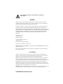
1
Title Page HSIM-SSR-600 Installation Guide SPD/100 XMT RCV CPU 9033040-01 HSIM-SSR-600 10/100 Only qualified personnel should perform installation procedures. NOTICE Cabletron Systems reserves the right to make changes in specifications and other information contained in this document without prior notice. The reader should in all cases consult Cabletron Systems to determine whether any such changes have been made. The hardware, firmware, or software described in this manual is subject to change without notice. IN NO EVENT SHALL CABLETRON SYSTEMS BE LIABLE FOR ANY INCIDENTAL, INDIRECT, SPECIAL, OR CONSEQUENTIAL DAMAGES WHATSOEVER (INCLUDING BUT NOT LIMITED TO LOST PROFITS) ARISING OUT OF OR RELATED TO THIS MANUAL OR THE INFORMATION CONTAINED IN IT, EVEN IF CABLETRON SYSTEMS HAS BEEN ADVISED OF, KNOWN, OR SHOULD HAVE KNOWN, THE POSSIBILITY OF SUCH DAMAGES. Cabletron Systems, Inc. 35 Industrial Way Rochester, NH 03867 1999 by Cabletron Systems, Inc. All Rights Reserved Printed in the United States of America Order Number: 9033040-01 December 1999 Cabletron Systems and LANVIEW are registered trademarks and SmartSwitch is a trademark of Cabletron Systems, Inc. All other product names mentioned in this manual may be trademarks or registered trademarks of their respective companies. FCC NOTICE This device complies with Part 15 of the FCC rules. Operation is subject to the following two conditions: (1) this device may not cause harmful interference, and (2) this device must accept any interference received, including interference that may cause undesired operation. NOTE: This equipment has been tested and found to comply with the limits for a Class A digital device, pursuant to Part 15 of the FCC rules. These limits are designed to provide reasonable protection against harmful interference when the equipment is operated in a commercial environment. This equipment uses, generates, and can radiate radio frequency energy and if not installed in accordance with the operator’s manual, may cause harmful interference to radio communications. Operation of this equipment in a residential area is likely to cause interference in which case the user will be required to correct the interference at his own expense. WARNING: Changes or modifications made to this device which are not expressly approved by the party responsible for compliance could void the user’s authority to operate the equipment. HSIM-SSR-600 Installation Guide i Notice INDUSTRY CANADA NOTICE This digital apparatus does not exceed the Class A limits for radio noise emissions from digital apparatus set out in the Radio Interference Regulations of the Canadian Department of Communications. Le présent appareil numérique n’émet pas de bruits radioélectriques dépassant les limites applicables aux appareils numériques de la class A prescrites dans le Règlement sur le brouillage radioélectrique édicté par le ministère des Communications du Canada. NOTICE: The Industry Canada label identifies certified equipment. This certification means that the equipment meets telecommunications network protective, operational and safety requirements as prescribed in the appropriate Terminal Equipment Technical Requirements documents (s). The department does not guarantee the equipment will operate to the user’s satisfaction. Before installing this equipment, users should ensure that it is permissible to be connected to the facilities of the local telecommunications company. The equipment must also be installed using an acceptable method of connection. The customer should be aware that compliance with the above conditions may not prevent degradation of service in some situations. Repairs to certified equipment should be coordinated by a representative designated by the supplier. Any repairs or alterations made by the user to this equipment, or equipment malfunctions, may give the telecommunications company cause to request the user to disconnect the equipment. Users should ensure for their own protection that the electrical ground connections of the power utility, telephone lines and internal metallic water pipe system, if present, are connected together. This precaution may be particularly important in rural areas. Caution: Users should not attempt to make such connections themselves, but should contact the appropriate electric inspection authority, or electrician, as appropriate. NOTICE: The Ringer Equivalence Number (REN) assigned to each terminal device provides an indication of the maximum number of terminals allowed to be connected to a telephone interface. The termination on an interface may consist of any combination of devices subject only to the requirement that the sum of the ringer equivalence Numbers of all the devices does not exceed 5. VCCI NOTICE This is a Class A product based on the standard of the Voluntary Control Council for Interference by Information Technology Equipment (VCCI). If this equipment is used in a domestic environment, radio disturbance may arise. When such trouble occurs, the user may be required to take corrective actions. ii HSIM-SSR-600 Installation Guide Notice CABLETRON SYSTEMS, INC. PROGRAM LICENSE AGREEMENT IMPORTANT: THIS LICENSE APPLIES FOR USE OF PRODUCT IN THE FOLLOWING GEOGRAPHICAL REGIONS: CANADA MEXICO CENTRAL AMERICA SOUTH AMERICA BEFORE OPENING OR UTILIZING THE ENCLOSED PRODUCT, CAREFULLY READ THIS LICENSE AGREEMENT. This document is an agreement (“Agreement”) between You, the end user, and Cabletron Systems, Inc. (“Cabletron”) that sets forth your rights and obligations with respect to the Cabletron software program (“Program”) in the package. The Program may be contained in firmware, chips or other media. UTILIZING THE ENCLOSED PRODUCT, YOU ARE AGREEING TO BECOME BOUND BY THE TERMS OF THIS AGREEMENT, WHICH INCLUDES THE LICENSE AND THE LIMITATION OF WARRANTY AND DISCLAIMER OF LIABILITY. IF YOU DO NOT AGREE TO THE TERMS OF THIS AGREEMENT, RETURN THE UNOPENED PRODUCT TO CABLETRON OR YOUR DEALER, IF ANY, WITHIN TEN (10) DAYS FOLLOWING THE DATE OF RECEIPT FOR A FULL REFUND. IF YOU HAVE ANY QUESTIONS ABOUT THIS AGREEMENT, CONTACT CABLETRON SYSTEMS +1-603-332-9400. Attn: Legal Department. 1. LICENSE. You have the right to use only the one (1) copy of the Program provided in this package subject to the terms and conditions of this License Agreement. You may not copy, reproduce or transmit any part of the Program except as permitted by the Copyright Act of the United States or as authorized in writing by Cabletron. 2. OTHER RESTRICTIONS. You may not reverse engineer, decompile, or disassemble the Program. 3. APPLICABLE LAW. This License Agreement shall be interpreted and governed under the laws and in the state and federal courts of New Hampshire. You accept the personal jurisdiction and venue of the New Hampshire courts. 4. EXPORT REQUIREMENTS. You understand that Cabletron and its Affiliates are subject to regulation by agencies of the U.S. Government, including the U.S. Department of Commerce, which prohibit export or diversion of certain technical products to certain countries, unless a license to export the product is obtained from the U.S. Government or an exception from obtaining such license may be relied upon by the exporting party. If the Program is exported from the United States pursuant to the License Exception CIV under the U.S. Export Administration Regulations, You agree that You are a civil end user of the Program and agree that You will use the Program for civil end uses only and not for military purposes. HSIM-SSR-600 Installation Guide iii Notice If the Program is exported from the United States pursuant to the License Exception TSR under the U.S. Export Administration Regulations, in addition to the restriction on transfer set forth in Sections 1 or 2 of this Agreement, You agree not to (i) reexport or release the Program, the source code for the Program or technology to a national of a country in Country Groups D:1 or E:2 (Albania, Armenia, Azerbaijan, Belarus, Bulgaria, Cambodia, Cuba, Estonia, Georgia, Iraq, Kazakhstan, Kyrgyzstan, Laos, Latvia, Libya, Lithuania, Moldova, North Korea, the People’s Republic of China, Romania, Russia, Rwanda, Tajikistan, Turkmenistan, Ukraine, Uzbekistan, Vietnam, or such other countries as may be designated by the United States Government), (ii) export to Country Groups D:1 or E:2 (as defined herein) the direct product of the Program or the technology, if such foreign produced direct product is subject to national security controls as identified on the U.S. Commerce Control List, or (iii) if the direct product of the technology is a complete plant o r any major component of a plant, export to Country Groups D:1 or E:2 the direct product of the plant or a major component thereof, if such foreign produced direct product is subject to national security controls as identified on the U.S. Commerce Control List or is subject to State Department controls under the U.S. Munitions List. 5. UNITED STATES GOVERNMENT RESTRICTED RIGHTS. The enclosed Product (i) was developed solely at private expense; (ii) contains “restricted computer software” submitted with restricted rights in accordance with section 52.227-19 (a) through (d) of the Commercial Computer Software-Restricted Rights Clause and its successors, and (iii) in all respects is proprietary data belonging to Cabletron and/or its suppliers. For Department of Defense units, the Product is considered commercial computer software in accordance with DFARS section 227.7202-3 and its successors, and use, duplication, or disclosure by the Government is subject to restrictions set forth herein. 6. EXCLUSION OF WARRANTY. Except as may be specifically provided by Cabletron in writing, Cabletron makes no warranty, expressed or implied, concerning the Program (including its documentation and media). CABLETRON DISCLAIMS ALL WARRANTIES, OTHER THAN THOSE SUPPLIED TO YOU BY CABLETRON IN WRITING, EITHER EXPRESS OR IMPLIED, INCLUDING BUT NOT LIMITED TO IMPLIED WARRANTIES OF MERCHANTABILITY AND FITNESS FOR A PARTICULAR PURPOSE, WITH RESPECT TO THE PROGRAM, THE ACCOMPANYING WRITTEN MATERIALS, AND ANY ACCOMPANYING HARDWARE. 7. NO LIABILITY FOR CONSEQUENTIAL DAMAGES. IN NO EVENT SHALL CABLETRON OR ITS SUPPLIERS BE LIABLE FOR ANY DAMAGES WHATSOEVER (INCLUDING, WITHOUT LIMITATION, DAMAGES FOR LOSS OF BUSINESS, PROFITS, BUSINESS INTERRUPTION, LOSS OF BUSINESS INFORMATION, SPECIAL, INCIDENTAL, CONSEQUENTIAL, OR RELIANCE DAMAGES, OR OTHER LOSS) ARISING OUT OF THE USE OR INABILITY TO USE THIS CABLETRON PRODUCT, EVEN IF CABLETRON HAS BEEN ADVISED OF THE POSSIBILITY OF SUCH DAMAGES. BECAUSE SOME STATES DO NOT ALLOW THE EXCLUSION OR LIMITATION OF LIABILITY FOR CONSEQUENTIAL OR INCIDENTAL DAMAGES, OR IN THE DURATION OR LIMITATION OF IMPLIED WARRANTIES IN SOME INSTANCES, THE ABOVE LIMITATION AND EXCLUSIONS MAY NOT APPLY TO YOU. iv HSIM-SSR-600 Installation Guide Notice CABLETRON SYSTEMS SALES AND SERVICE, INC. PROGRAM LICENSE AGREEMENT IMPORTANT: THIS LICENSE APPLIES FOR USE OF PRODUCT IN THE UNITED STATES OF AMERICA AND BY UNITED STATES OF AMERICA GOVERNMENT END USERS. BEFORE OPENING OR UTILIZING THE ENCLOSED PRODUCT, CAREFULLY READ THIS LICENSE AGREEMENT. This document is an agreement (“Agreement”) between You, the end user, and Cabletron Systems Sales and Service, Inc. (“Cabletron”) that sets forth your rights and obligations with respect to the Cabletron software program (“Program”) in the package. The Program may be contained in firmware, chips or other media. UTILIZING THE ENCLOSED PRODUCT, YOU ARE AGREEING TO BECOME BOUND BY THE TERMS OF THIS AGREEMENT, WHICH INCLUDES THE LICENSE AND THE LIMITATION OF WARRANTY AND DISCLAIMER OF LIABILITY. IF YOU DO NOT AGREE TO THE TERMS OF THIS AGREEMENT, RETURN THE UNOPENED PRODUCT TO CABLETRON OR YOUR DEALER, IF ANY, WITHIN TEN (10) DAYS FOLLOWING THE DATE OF RECEIPT FOR A FULL REFUND. IF YOU HAVE ANY QUESTIONS ABOUT THIS AGREEMENT, CONTACT CABLETRON SYSTEMS +1-603-332-9400. Attn: Legal Department. 1. LICENSE. You have the right to use only the one (1) copy of the Program provided in this package subject to the terms and conditions of this License Agreement. You may not copy, reproduce or transmit any part of the Program except as permitted by the Copyright Act of the United States or as authorized in writing by Cabletron. 2. OTHER RESTRICTIONS. You may not reverse engineer, decompile, or disassemble the Program. 3. APPLICABLE LAW. This License Agreement shall be interpreted and governed under the laws and in the state and federal courts of New Hampshire. You accept the personal jurisdiction and venue of the New Hampshire courts. 4. EXPORT REQUIREMENTS. You understand that Cabletron and its Affiliates are subject to regulation by agencies of the U.S. Government, including the U.S. Department of Commerce, which prohibit export or diversion of certain technical products to certain countries, unless a license to export the product is obtained from the U.S. Government or an exception from obtaining such license may be relied upon by the exporting party. If the Program is exported from the United States pursuant to the License Exception CIV under the U.S. Export Administration Regulations, You agree that You are a civil end user of the Program and agree that You will use the Program for civil end uses only and not for military purposes. HSIM-SSR-600 Installation Guide v Notice If the Program is exported from the United States pursuant to the License Exception TSR under the U.S. Export Administration Regulations, in addition to the restriction on transfer set forth in Sections 1 or 2 of this Agreement, You agree not to (i) reexport or release the Program, the source code for the Program or technology to a national of a country in Country Groups D:1 or E:2 (Albania, Armenia, Azerbaijan, Belarus, Bulgaria, Cambodia, Cuba, Estonia, Georgia, Iraq, Kazakhstan, Kyrgyzstan, Laos, Latvia, Libya, Lithuania, Moldova, North Korea, the People’s Republic of China, Romania, Russia, Rwanda, Tajikistan, Turkmenistan, Ukraine, Uzbekistan, Vietnam, or such other countries as may be designated by the United States Government), (ii) export to Country Groups D:1 or E:2 (as defined herein) the direct product of the Program or the technology, if such foreign produced direct product is subject to national security controls as identified on the U.S. Commerce Control List, or (iii) if the direct product of the technology is a complete plant o r any major component of a plant, export to Country Groups D:1 or E:2 the direct product of the plant or a major component thereof, if such foreign produced direct product is subject to national security controls as identified on the U.S. Commerce Control List or is subject to State Department controls under the U.S. Munitions List. 5. UNITED STATES GOVERNMENT RESTRICTED RIGHTS. The enclosed Product (i) was developed solely at private expense; (ii) contains “restricted computer software” submitted with restricted rights in accordance with section 52.227-19 (a) through (d) of the Commercial Computer Software-Restricted Rights Clause and its successors, and (iii) in all respects is proprietary data belonging to Cabletron and/or its suppliers. For Department of Defense units, the Product is considered commercial computer software in accordance with DFARS section 227.7202-3 and its successors, and use, duplication, or disclosure by the Government is subject to restrictions set forth herein. 6. EXCLUSION OF WARRANTY. Except as may be specifically provided by Cabletron in writing, Cabletron makes no warranty, expressed or implied, concerning the Program (including its documentation and media). CABLETRON DISCLAIMS ALL WARRANTIES, OTHER THAN THOSE SUPPLIED TO YOU BY CABLETRON IN WRITING, EITHER EXPRESS OR IMPLIED, INCLUDING BUT NOT LIMITED TO IMPLIED WARRANTIES OF MERCHANTABILITY AND FITNESS FOR A PARTICULAR PURPOSE, WITH RESPECT TO THE PROGRAM, THE ACCOMPANYING WRITTEN MATERIALS, AND ANY ACCOMPANYING HARDWARE. 7. NO LIABILITY FOR CONSEQUENTIAL DAMAGES. IN NO EVENT SHALL CABLETRON OR ITS SUPPLIERS BE LIABLE FOR ANY DAMAGES WHATSOEVER (INCLUDING, WITHOUT LIMITATION, DAMAGES FOR LOSS OF BUSINESS, PROFITS, BUSINESS INTERRUPTION, LOSS OF BUSINESS INFORMATION, SPECIAL, INCIDENTAL, CONSEQUENTIAL, OR RELIANCE DAMAGES, OR OTHER LOSS) ARISING OUT OF THE USE OR INABILITY TO USE THIS CABLETRON PRODUCT, EVEN IF CABLETRON HAS BEEN ADVISED OF THE POSSIBILITY OF SUCH DAMAGES. BECAUSE SOME STATES DO NOT ALLOW THE EXCLUSION OR LIMITATION OF LIABILITY FOR CONSEQUENTIAL OR INCIDENTAL DAMAGES, OR IN THE DURATION OR LIMITATION OF IMPLIED WARRANTIES IN SOME INSTANCES, THE ABOVE LIMITATION AND EXCLUSIONS MAY NOT APPLY TO YOU. vi HSIM-SSR-600 Installation Guide Notice CABLETRON SYSTEMS LIMITED PROGRAM LICENSE AGREEMENT IMPORTANT: THIS LICENSE APPLIES FOR THE USE OF THE PRODUCT IN THE FOLLOWING GEOGRAPHICAL REGIONS: EUROPE MIDDLE EAST AFRICA ASIA AUSTRALIA PACIFIC RIM BEFORE OPENING OR UTILIZING THE ENCLOSED PRODUCT, CAREFULLY READ THIS LICENSE AGREEMENT. This document is an agreement (“Agreement”) between You, the end user, and Cabletron Systems Limited (“Cabletron”) that sets forth your rights and obligations with respect to the Cabletron software program (“Program”) in the package. The Program may be contained in firmware, chips or other media. UTILIZING THE ENCLOSED PRODUCT, YOU ARE AGREEING TO BECOME BOUND BY THE TERMS OF THIS AGREEMENT, WHICH INCLUDES THE LICENSE AND THE LIMITATION OF WARRANTY AND DISCLAIMER OF LIABILITY. IF YOU DO NOT AGREE TO THE TERMS OF THIS AGREEMENT, RETURN THE UNOPENED PRODUCT TO CABLETRON OR YOUR DEALER, IF ANY, WITHIN TEN (10) DAYS FOLLOWING THE DATE OF RECEIPT FOR A FULL REFUND. IF YOU HAVE ANY QUESTIONS ABOUT THIS AGREEMENT, CONTACT CABLETRON SYSTEMS +1-603-332-9400. Attn: Legal Department. 1. LICENSE. You have the right to use only the one (1) copy of the Program provided in this package subject to the terms and conditions of this License Agreement. You may not copy, reproduce or transmit any part of the Program except as permitted by the Copyright Act of the United States or as authorized in writing by Cabletron. 2. OTHER RESTRICTIONS. You may not reverse engineer, decompile, or disassemble the Program. 3. APPLICABLE LAW. This License Agreement shall be governed in accordance with English law. The English courts shall have exclusive jurisdiction in the event of any disputes. 4. EXPORT REQUIREMENTS. You understand that Cabletron and its Affiliates are subject to regulation by agencies of the U.S. Government, including the U.S. Department of Commerce, which prohibit export or diversion of certain technical products to certain countries, unless a license to export the product is obtained from the U.S. Government or an exception from obtaining such license may be relied upon by the exporting party. If the Program is exported from the United States pursuant to the License Exception CIV under the U.S. Export Administration Regulations, You agree that You are a civil end user of the Program and agree that You will use the Program for civil end uses only and not for military purposes. HSIM-SSR-600 Installation Guide vii Notice If the Program is exported from the United States pursuant to the License Exception TSR under the U.S. Export Administration Regulations, in addition to the restriction on transfer set forth in Sections 1 or 2 of this Agreement, You agree not to (i) reexport or release the Program, the source code for the Program or technology to a national of a country in Country Groups D:1 or E:2 (Albania, Armenia, Azerbaijan, Belarus, Bulgaria, Cambodia, Cuba, Estonia, Georgia, Iraq, Kazakhstan, Kyrgyzstan, Laos, Latvia, Libya, Lithuania, Moldova, North Korea, the People’s Republic of China, Romania, Russia, Rwanda, Tajikistan, Turkmenistan, Ukraine, Uzbekistan, Vietnam, or such other countries as may be designated by the United States Government), (ii) export to Country Groups D:1 or E:2 (as defined herein) the direct product of the Program or the technology, if such foreign produced direct product is subject to national security controls as identified on the U.S. Commerce Control List, or (iii) if the direct product of the technology is a complete plant o r any major component of a plant, export to Country Groups D:1 or E:2 the direct product of the plant or a major component thereof, if such foreign produced direct product is subject to national security controls as identified on the U.S. Commerce Control List or is subject to State Department controls under the U.S. Munitions List. 5. UNITED STATES GOVERNMENT RESTRICTED RIGHTS. The enclosed Product (i) was developed solely at private expense; (ii) contains “restricted computer software” submitted with restricted rights in accordance with section 52.227-19 (a) through (d) of the Commercial Computer Software-Restricted Rights Clause and its successors, and (iii) in all respects is proprietary data belonging to Cabletron and/or its suppliers. For Department of Defense units, the Product is considered commercial computer software in accordance with DFARS section 227.7202-3 and its successors, and use, duplication, or disclosure by the Government is subject to restrictions set forth herein. 6. EXCLUSION OF WARRANTY. Except as may be specifically provided by Cabletron in writing, Cabletron makes no warranty, expressed or implied, concerning the Program (including its documentation and media). CABLETRON DISCLAIMS ALL WARRANTIES, OTHER THAN THOSE SUPPLIED TO YOU BY CABLETRON IN WRITING, EITHER EXPRESS OR IMPLIED, INCLUDING BUT NOT LIMITED TO IMPLIED WARRANTIES OF MERCHANTABILITY AND FITNESS FOR A PARTICULAR PURPOSE, WITH RESPECT TO THE PROGRAM, THE ACCOMPANYING WRITTEN MATERIALS, AND ANY ACCOMPANYING HARDWARE. 7. NO LIABILITY FOR CONSEQUENTIAL DAMAGES. IN NO EVENT SHALL CABLETRON OR ITS SUPPLIERS BE LIABLE FOR ANY DAMAGES WHATSOEVER (INCLUDING, WITHOUT LIMITATION, DAMAGES FOR LOSS OF BUSINESS, PROFITS, BUSINESS INTERRUPTION, LOSS OF BUSINESS INFORMATION, SPECIAL, INCIDENTAL, CONSEQUENTIAL, OR RELIANCE DAMAGES, OR OTHER LOSS) ARISING OUT OF THE USE OR INABILITY TO USE THIS CABLETRON PRODUCT, EVEN IF CABLETRON HAS BEEN ADVISED OF THE POSSIBILITY OF SUCH DAMAGES. BECAUSE SOME STATES DO NOT ALLOW THE EXCLUSION OR LIMITATION OF LIABILITY FOR CONSEQUENTIAL OR INCIDENTAL DAMAGES, OR IN THE DURATION OR LIMITATION OF IMPLIED WARRANTIES IN SOME INSTANCES, THE ABOVE LIMITATION AND EXCLUSIONS MAY NOT APPLY TO YOU. viii HSIM-SSR-600 Installation Guide Notice DECLARATION OF CONFORMITY Application of Council Directive(s): Manufacturer’s Name: Manufacturer’s Address: European Representative Name: European Representative Address: Conformance to Directive(s)/Product Standards: Equipment Type/Environment: 89/336/EEC 73/23/EEC Cabletron Systems, Inc. 35 Industrial Way PO Box 5005 Rochester, NH 03867 Mr. J. Solari Cabletron Systems Limited Nexus House, Newbury Business Park London Road, Newbury Berkshire RG14 2PZ, England EC Directive 89/336/EEC EC Directive 73/23/EEC EN 55022 EN 50082-1 EN 60950 Networking Equipment, for use in a Commercial or Light Industrial Environment. We the undersigned, hereby declare, under our sole responsibility, that the equipment packaged with this notice conforms to the above directives. Manufacturer Legal Representative in Europe Mr. Ronald Fotino ___________________________________ Full Name Mr. J. Solari ___________________________________ Full Name Compliance Engineering Manager ___________________________________ Title Managing Director - E.M.E.A. ___________________________________ Title Rochester, NH, USA ___________________________________ Location Newbury, Berkshire, England ___________________________________ Location HSIM-SSR-600 Installation Guide ix Notice x HSIM-SSR-600 Installation Guide CONTENTS Figures ................................................................................................... xiii Tables..................................................................................................... xiv INTRODUCTION Using This Guide ...........................................................................xv Structure of This Guide................................................................. xvi HSIM-SSR-600 Features.............................................................. xvi Optional Features ........................................................................ xvii Related Manuals......................................................................... xviii Document Conventions ................................................................ xix Getting Help...................................................................................xx CHAPTER 1 NETWORK REQUIREMENTS 1.1 10/100 Ethernet/Console Port ..................................................... 1-1 1.2 10BASE-T Network ..................................................................... 1-2 1.3 100BASE-TX Network ................................................................. 1-2 1.4 WAN Network Requirements....................................................... 1-2 CHAPTER 2 INSTALLATION 2.1 Unpacking the HSIM-SSR-600.................................................... 2-1 2.2 Installing the HSIM-SSR-600....................................................... 2-2 2.3 Installing Options ......................................................................... 2-2 2.3.1 Optional SSR-600-ECM Installation ............................... 2-3 2.3.2 Installing Sliding WAN Physical Interface Modules ........ 2-4 2.3.3 Installing the HSIM-SSR-600 in an Interface Module ..... 2-5 2.3.4 Installing the HSIM-SSR-600 in a Standalone Device .... 2-7 2.4 Connecting the HSIM-SSR-600 to the Network .......................... 2-9 2.4.1 Ethernet LAN Connection ............................................... 2-9 2.4.2 Connecting to the Fast Ethernet Port ............................. 2-9 2.4.3 Connecting SWPIMs to the WAN ................................. 2-12 2.5 Software Configuration .............................................................. 2-13 HSIM-SSR-600 Installation Guide xi Contents CHAPTER 3 3.1 3.2 3.3 3.4 3.5 TROUBLESHOOTING, SWITCHES, AND LED INDICATIONS Front Panel LED Indications ........................................................3-2 Console Management/Ethernet Port............................................3-3 Switches.......................................................................................3-3 3.3.1 Switch Function Procedure .............................................3-4 Troubleshooting HSIM-SSR-600 Hardware .................................3-6 Troubleshooting the LAN (10/100 Ethernet Port Connection) .....3-6 APPENDIX A SPECIFICATIONS A.1 Physical Properties ..................................................................... A-1 A.2 Fast Ethernet/Console Port Pinout ............................................. A-1 A.3 Cable Adapter Pinout.................................................................. A-2 A.4 Environmental Requirements...................................................... A-2 A.5 Regulatory Compliance............................................................... A-3 xii HSIM-SSR-600 Installation Guide FIGURES Figure 2-1 2-2 2-3 2-4 2-5 2-6 2-7 2-8 2-9 3-1 3-2 Page SSR-600-ECM Installation Area............................................... 2-3 WAN SWPIM Ports .................................................................. 2-4 Removing an Existing SWPIM ................................................. 2-4 Removing the HSIM Coverplate............................................... 2-5 Installing the HSIM-SSR-600 ................................................... 2-6 Connecting a Twisted Pair Ethernet Segment ....................... 2-10 Crossover Cable RJ45 Pinouts .............................................. 2-11 Straight-Through Cable RJ45 Pinouts.................................... 2-11 Connecting a Local Management Cable ................................ 2-13 HSIM-SSR-600 Front Panel LEDs ........................................... 3-1 Switch Bank Layout.................................................................. 3-5 HSIM-SSR-600 Installation Guide xiii TABLES Table 3-1 3-2 A-1 A-2 Page HSIM-SSR-600 LAN LEDs....................................................... 3-2 Four-Position Switch Functions ............................................... 3-4 Fast Ethernet / Console Port Connector Pinout .......................A-1 Cable Adapter Pinout (Part Number 9360222) ........................A-2 HSIM-SSR-600 Installation Guide xiv INTRODUCTION Only qualified personnel should perform installation procedures. Welcome to the Cabletron Systems HSIM-SSR-600 Installation Guide. HSIM stands for High Speed Interface Module, and SSR stands for SmartSwitch Router. This guide provides installation, basic configuration information, hardware specifications and troubleshooting tips for the HSIM-SSR-600. The HSIM-SSR-600 is a module that can be installed into a host platform. It has two optional SWPIM WAN ports and a Local Management console port that can also be used for 10/100 Ethernet. There is also an Auxiliary card option slot for the SSR-600-ECM, a hardware encryption/compression module. Installation instructions for the SSR-600-ECM module are in Section 2.3. The HSIM-SSR-600 can be installed into a compatible Cabletron Systems host platform, such as a SmartSwitch 2000 (2nd generation) or 6000 (2nd generation) series device that has an HSIM slot, and therefore is capable of having the HSIM-SSR-600 installed into it. NOTE The term “host platform” may be used to indicate a compatible Cabletron Systems device into which the HSIM-SSR-600 can be installed, such as a 6H133-37 interface module or a 2H252-25 standalone device. USING THIS GUIDE Read through this guide completely to familiarize yourself with its content and to gain an understanding of the features and capabilities of the HSIM-SSR-600. A general working knowledge of WAN, Ethernet and IEEE 802.3 data communications networks, and their physical layer components is helpful before using the HSIM-SSR-600. HSIM-SSR-600 Installation Guide xv Introduction STRUCTURE OF THIS GUIDE This guide is organized as follows: This Introduction provides preliminary information that will aid in using this manual. It lists technology and user’s guides that may help the user to set up and manage the HSIM-SSR-600, and provides an overview of the HSIM-SSR-600 and its features, and provides instructions on how to get help from Cabletron Systems. Chapter 1, Network Requirements, outlines the network requirements that must be met before installing the HSIM-SSR-600 into a network. Chapter 2, Installation, provides installation instructions for the HSIM-SSR-600. Chapter 3, Troubleshooting, Switches, and LED Indications, provides detailed troubleshooting tips using the LANVIEW LEDs on the HSIM-SSR-600 and details the hardware features of the HSIM-SSR-600. Appendix A, Specifications, contains information on functionality and operating specifications, regulatory compliance, environmental requirements, and physical properties. HSIM-SSR-600 FEATURES The HSIM-SSR-600 is an access device that provides Ethernet Local Area Network (LAN) connectivity via one Fast Ethernet port, and offers high-speed Wide Area Network (WAN) access to remote sites via two Sliding WAN Physical Interface Modules (SWPIMs). The HSIM-SSR-600 can be installed into any compatible Cabletron Systems host platform. Refer to the appropriate Cabletron Systems software manual (listed under Related Manuals) for information on supported WAN protocols and how to configure the HSIM-SSR-600 using software. The HSIM-SSR-600 can be remotely managed with Cabletron Routing Software, or a third party SNMP compliant network management system. xvi HSIM-SSR-600 Installation Guide Introduction OPTIONAL FEATURES Optional features for the HSIM-SSR-600 include the SSR-600-ECM auxiliary card, which performs encryption or compression, and the SWPIMs (Sliding WAN Physical Interface Modules), listed below. • The SWPIM-T1 provides a T1 interface through a front panel RJ45 port and includes a built-in Channel Service Unit/Digital Service Unit (CSU/DSU) for direct connection to a T1 line. The SWPIM-T1 provides both Full T1 or Fractional T1 using 56 or 64 Kbps Time Slots, with a total throughput of up to 1.544 Mbps (1.536 payload bandwidth). • The SWPIM-SY provides a synchronous serial connection of up to 2.048 Mbps to external communications equipment (e.g., a multiplexer or CSU/DSU). The SWPIM-SY uses a subminiature 36-pin connector that supports these electrical signal interfaces: EIA-RS449, V.35, EIA-RS232D, X.21, EIA-RS530, EIA-530A. • The SWPIM-DDS provides a 56 Kbps or 64 Kbps Digital Data Service (DDS) connection. The SWPIM-DDS supports remote CSU diagnostic or 64 Kbps clear channel loopback and non-latching remote DSU diagnostic loopback. • The SWPIM-E1 provides an E1 interface through a front panel RJ45 port and includes a built-in CSU/DSU for direct connection to an E1 line. The SWPIM-E1 provides both Full E1 or Fractional E1 using 56 or 64 Kbps Time Slots with a total throughput of up to 2.048 Mbps (1.984 Mbps payload bandwidth). Check the Release Notes for further information on available SWPIMs. HSIM-SSR-600 Installation Guide xvii Introduction RELATED MANUALS The following manuals may help the user to set up and manage the HSIM-SSR-600: Cabletron Systems Ethernet Technology Guide Cabletron Systems Cabling Guide The applicable Cabletron Systems SWPIM manual(s) The manuals referenced above can be obtained on the World Wide Web in Adobe Acrobat Portable Document Format (PDF) at the following site: http://www.cabletron.com/ Cabletron Systems applicable software manuals for the SSR-600 and the HSIM-SSR-600 host platforms (Cabletron Routing Software Manuals): Bridging Configuration Guide Event Logging System Message Guide Network Interface Operations Guide Routing Protocols Reference Guide Routing Protocols User’s Guide System Software Guide ClearVISN Routing Configurator User’s Guide Systems Network Architecture Guide Quick Reference Guide Data Trace Facility xviii HSIM-SSR-600 Installation Guide Introduction DOCUMENT CONVENTIONS The following conventions may be used in this document: NOTE TIP ! Note symbol. Calls the reader’s attention to any item of information that may be of special importance. Tip symbol. Conveys helpful hints concerning procedures or actions. Caution symbol. Contains information essential to avoid damage to the equipment. CAUTION Electrical Hazard Warning symbol. Warns against an action that could result in personal injury or death due to an electrical hazard. HSIM-SSR-600 Installation Guide xix Introduction GETTING HELP For additional support related to this device or document, contact Cabletron Systems using one of the following methods: World Wide Web http://www.cabletron.com/ Phone (603) 332-9400 Internet mail [email protected] FTP ftp://ftp.cabletron.com/ anonymous your email address Login Password To send comments or suggestions concerning this document, contact the Cabletron Systems Technical Writing Department via the following email address: [email protected] Make sure to include the document Part Number in the email message. Before calling Cabletron Systems, have the following information ready: • Your Cabletron Systems service contract number • A description of the failure • A description of any action(s) already taken to resolve the problem (e.g., changing mode switches, rebooting the unit, etc.) • The serial and revision numbers of all involved Cabletron Systems products in the network • A description of your network environment (layout, cable type, etc.) • Network load and frame size at the time of trouble (if known) • The device history (i.e., have you returned the device before, is this a recurring problem, etc.) • Any previous Return Material Authorization (RMA) numbers xx HSIM-SSR-600 Installation Guide CHAPTER 1 NETWORK REQUIREMENTS Before installing the HSIM-SSR-600, review the requirements and specifications referred to in this chapter concerning the following: • 10BASE-T Twisted Pair Network (Section 1.2) • 100BASE-TX Twisted Pair Network (Section 1.3) The network installation must meet the guidelines in this chapter and in the documents referenced in this chapter to ensure satisfactory performance of the equipment. Failure to follow the guidelines may produce poor network performance. If the device connected to the Ethernet port of the HSIM-SSR-600 cannot perform auto-detection, the speed for the HSIM-SSR-600 must be manually set. The guidelines in Section 1.2 and Section 1.3 are specifically for the fixed twisted pair front panel port only, labeled 10/100 on the HSIM-SSR-600. For the different SWPIMs that can be installed in the SWPIM slots, refer to the applicable installation guide for the specific SWPIM. NOTE 1.1 The Cabletron Systems Cabling Guide, referred to in the following sections, can be found on the Cabletron Systems World Wide Web site: http://www.cabletron.com/ 10/100 ETHERNET/CONSOLE PORT The port labeled 10/100 is used for Ethernet and can also operate as a console port for Local Management, but not simultaneously. The Ethernet cable is connected directly to the 10/100 port, but a special cable adapter is used to connect the port for Local Management. The adapter, part number 9360222, is shipped with the HSIM-SSR-600. Refer to Section 2.4 for information on connecting the port to Ethernet, and Section 2.5 for information on connecting the port for Local Management. ! Do not connect this port to a Local Management monitor without using the special cable adapter. CAUTION HSIM-SSR-600 Installation Guide 1-1 Chapter 1: Network Requirements 1.2 10BASE-T NETWORK When connecting a 10BASE-T segment to the HSIM-SSR-600 port, ensure that the network meets the Ethernet network requirements of the IEEE 802.3 standard for 10BASE-T. Refer to the Cabletron Systems Cabling Guide for details. NOTE 1.3 If a port is to operate at 100 Mbps, Category 5 cabling must be used. For 10 Mbps operation only, Category 3 cabling can be used. Refer to Section 1.3 for information about 100BASE-TX networks and cabling. 100BASE-TX NETWORK The 10/100 front panel port of the HSIM-SSR-600 provides an RJ45 connection that supports Category 5 UTP cabling for 100 Mbps operation. Do not use the special cable adapter when making a connection to Ethernet. The device at the other end of the twisted pair segment must meet IEEE 802.3u 100BASE-TX Fast Ethernet network requirements for the devices to operate at 100 Mbps. Refer to the Cabletron Systems Cabling Guide for details. NOTE The 10/100 port of the HSIM-SSR-600 supports Category 5 UTP cabling with an impedance between 85 and 111 ohms for 10 and 100 Mbps operation. The HSIM-SSR-600 is capable of operating at either 10 or 100 Mbps. The HSIM-SSR-600 can automatically sense the speed of the other Cabletron device and adjust its speed accordingly. 1.4 WAN NETWORK REQUIREMENTS Each SWPIM has to meet its own cabling and network requirements to be properly connected to the WAN. Please refer to the appropriate SWPIM user’s guide in order to follow the specific requirements. Refer to Optional Features in the Introduction for more information on the SWPIMs. 1-2 HSIM-SSR-600 Installation Guide CHAPTER 2 INSTALLATION To install the HSIM-SSR-600 the following items are required: • Antistatic wrist strap (shipped with the HSIM-SSR-600) • Phillips screwdriver • Cable adapter, Part Number 9360222, (shipped with the HSIM-SSR-600), needed to connect the Local Management port NOTE 2.1 Before attempting to use the HSIM-SSR-600 you should be familiar with the IEEE 802.3 Specifications, and T1 Networking. UNPACKING THE HSIM-SSR-600 ! CAUTION The HSIM-SSR-600 and the host platform are sensitive to static discharges. Use an antistatic strap and observe all static precautions during this procedure. Failure to do so could result in damage to the HSIM-SSR-600 or host platform. Unpack the HSIM-SSR-600 as follows: 1. Remove the HSIM-SSR-600 from the shipping box. 2. Leave the module in its antistatic bag until you are ready to install it. 3. Attach the antistatic wrist strap (refer to the instructions on the antistatic wrist strap package for proper use). Do not remove the strap until told to do so. 4. After removing the module from its antistatic bag, visually inspect the device. If you notice any signs of damage, contact Cabletron Systems immediately. Refer to Getting Help for instructions. Save the antistatic bag in the event the module must be reshipped or relocated. 5. Read any HSIM-SSR-600 Release Notes included in the shipping box for important up-to-date information before proceeding. HSIM-SSR-600 Installation Guide 2-1 Chapter 2: Installation 2.2 INSTALLING THE HSIM-SSR-600 Only qualified personnel should install or service this unit. An HSIM-SSR-600 can be installed in any second generation Cabletron Systems device that supports HSIM technology (e.g., 2H252-25R, 2H253-25, 6H252-17). NOTE Refer to the Release Notes for the version of firmware running on the Cabletron Systems host platform to ensure that the HSIM-SSR-600 is supported. The following subsections provide instructions for installing an HSIM-SSR-600 in a host platform. Refer to the specific interface module or standalone device manual for exact HSIM slot and connector locations. 2.3 INSTALLING OPTIONS If purchased, the SSR-600-ECM auxiliary card should be installed before proceeding. Refer to Section 2.3.1. The Cabletron Systems Sliding WAN Physical Interface Modules (SWPIMs) can be installed before or after the SSR-600-ECM installation. Refer to Section 2.3.2. ! CAUTION 2-2 The SWPIM and SSR-600-ECM options are sensitive to static discharges. Use a grounding strap and observe all static precautions during installation. Failure to do so could result in damage to the SWPIMs, SSR-600-ECM, or the HSIM-SSR-600. HSIM-SSR-600 Installation Guide Installing Options 2.3.1 ! CAUTION Optional SSR-600-ECM Installation Failure to follow the procedures in the indicated documentation can lead to damage to either the installed option or the HSIM-SSR-600. Figure 2-1 details the board layout of the HSIM-SSR-600 to show where the SSR-600-ECM Auxilliary Card can be installed. To properly install an SSR-600-ECM to enhance the encryption/compression performance of the HSIM-SSR-600, refer to the instructions enclosed with the SSR-600-ECM. SSR-600-ECM Auxiliary Card Installation Area Figure 2-1 SSR-600-ECM Installation Area HSIM-SSR-600 Installation Guide 2-3 Chapter 2: Installation 2.3.2 Installing Sliding WAN Physical Interface Modules The HSIM-SSR-600 can have up to two Sliding WAN Physical Interface Modules (SWPIMs) installed. Figure 2-2 indicates the ports in the HSIM-SSR-600 into which the SWPIMs can be installed. SWPIMs may be installed before or after the HSIM-SSR-600 is installed in the host platform. Refer to the applicable SWPIM Installation Guide for information on how to safely install an SWPIM in the HSIM-SSR-600 to enhance the capabilities of your HSIM-SSR-600. ! Failure to follow the procedures in the proper SWPIM manual can lead to damage to the SWPIM or the HSIM-SSR-600. CAUTION SPD/100 HSIM-SSR-600 10/100 XMT RCV CPU SWPIM Installation Ports Figure 2-2 WAN SWPIM Ports After installing the SWPIM, refer to the applicable software guide for information on how to configure the SWPIMs for connection to the WAN. Refer to Related Manuals in the Introduction. SWPIM Figure 2-3 Mounting Screw Removing an Existing SWPIM To remove an existing SWPIM, refer to Figure 2-3. Unfasten the mounting screw and carefully pull the SWPIM straight out of the HSIM-SSR-600. Refer to the static electricity cautions in Section 2.3. 2-4 HSIM-SSR-600 Installation Guide Installing Options 2.3.3 Installing the HSIM-SSR-600 in an Interface Module To install an HSIM-SSR-600 in an interface module that supports HSIM technology, perform the following steps. 1. Note the ports of the interface module that have cables attached to them. Write down the ports and label the cables to make it easier to reattach the network properly after the installation. Then disconnect those cables from the ports. 2. Attach the antistatic wrist strap (refer to the instructions outlined on the antistatic wrist strap package). 3. If the interface module is installed in a chassis, unlock the top and bottom plastic locking tabs of the module faceplate. 4. Remove the module from the chassis, and place it down flat with the internal components facing up. 5. Remove and save the two faceplate mounting screws securing the HSIM coverplate and remove the coverplate. See Figure 2-4. HSIM Coverplate Faceplate Mounting Screws Host Platform 2555_03 Figure 2-4 Removing the HSIM Coverplate HSIM-SSR-600 Installation Guide 2-5 Chapter 2: Installation 6. Refer to Figure 2-5 and place the HSIM-SSR-600 behind the module faceplate. Standoff Screws Connector Connector Cutaway view of connector HSIM-SSR-600 Standoff SP D/ 10 0 XM T RC HSIM Pins HS IM -S 10 SR /10 60 0 0 V CP U id Standoff Faceplate Mounting Screws Interface Module or Device (Host Platform) Figure 2-5 Installing the HSIM-SSR-600 7. Align the connector on the HSIM-SSR-600 with the pins on the module. ! CAUTION 2-6 When installing the HSIM-SSR-600, ensure that the connector aligns with the module connector pins to prevent bending the pins. Damage to both the HSIM-SSR-600 and the module can result if they are not properly aligned. HSIM-SSR-600 Installation Guide Installing Options 8. Press down firmly on the connector area of the HSIM-SSR-600 until the connector slides all the way onto the pins. Ensure that the standoffs on the interface module align with the standoff screw holes on the HSIM-SSR-600. 9. Fasten the HSIM-SSR-600 to the module faceplate using the mounting screws saved in step 5. Do not fully tighten the screws yet. 10. Fasten the HSIM-SSR-600 to the module standoffs using the standoff screws included in the HSIM-SSR-600 shipping materials. Do not fully tighten the screws yet. 11. Ensure that the HSIM-SSR-600 is positioned properly with respect to the screw holes and standoffs and securely fasten all screws at this time. 12. Reinstall the interface module in the chassis. 13. You may now remove the antistatic wrist strap. 14. Reattach the network cabling to the interface module. 2.3.4 Installing the HSIM-SSR-600 in a Standalone Device To install an HSIM-SSR-600 into a standalone device (e.g., 2H252-25R) perform the following steps: 1. Power down the device and remove the power cord. 2. Note the ports that have cables attached to them. Write down the ports and label the cables to make it easier to reattach the network properly after the installation. Then disconnect those cables from the ports. To install the HSIM-SSR-600 in a standalone device, the device must first be powered down. Ensure that you unplug the power cord and remove ONLY the screws required to remove the chassis cover. 3. Attach the antistatic wrist strap (refer to the instructions outlined on the antistatic wrist strap package). Do not remove the strap until told to do so. HSIM-SSR-600 Installation Guide 2-7 Chapter 2: Installation 4. Remove the standalone device chassis cover (refer to the specific standalone device documentation for instructions on removing the chassis cover). 5. Refer back to Figure 2-4 and remove the two faceplate mounting screws and the HSIM coverplate. Save the screws. 6. Refer back to Figure 2-5 and place the HSIM-SSR-600 behind the standalone device faceplate. 7. Align the HSIM connector of the HSIM-SSR-600 with the connector pins on the standalone device. ! CAUTION When installing the HSIM-SSR-600, ensure that the connector aligns with the device connector pins to prevent bending the pins. Damage to both the HSIM-SSR-600 and the device can result if they are not properly aligned. 8. Press down firmly on the HSIM-SSR-600 until the connector slides all the way onto the HSIM pins. Ensure that the standoffs on the standalone device align with the standoff screw holes on the HSIM-SSR-600. 9. Secure the HSIM-SSR-600 to the module faceplate using the mounting screws saved in step 5. Do not fully tighten the screws yet. 10. Secure the HSIM-SSR-600 to the module standoffs using the standoff screws included in the HSIM-SSR-600 shipping materials. Do not fully tighten the screws yet. 11. Ensure that the HSIM-SSR-600 is positioned properly with respect to the screw holes and standoffs and securely fasten all screws at this time. Ensure that the chassis cover is in place before reconnecting the power cord. 12. Replace the chassis cover on the standalone device, reconnect the power cord, and reconnect the standalone device to the network. 13. You may now remove the antistatic wrist strap. 2-8 HSIM-SSR-600 Installation Guide Connecting the HSIM-SSR-600 to the Network 2.4 CONNECTING THE HSIM-SSR-600 TO THE NETWORK Refer to Related Manuals in the Introduction to find the appropriate software manual to configure the host device. The WAN connection must be configured in software before the physical WAN cable connection is made to the network. Refer to the appropriate SWPIM manual for information on connecting the SWPIM to the network. Failure to use the correct cable and setup may cause problems on the network. 2.4.1 Ethernet LAN Connection The HSIM-SSR-600 provides 10/100 Mbps Ethernet/IEEE 802.3 support through the front panel Fast Ethernet port. Refer to Chapter 1 for more information on Ethernet configuration requirements. 2.4.2 Connecting to the Fast Ethernet Port The 10/100 Fast Ethernet port has an internal crossover. When connecting a workstation to the HSIM-SSR-600, use a straight-through cable. When connecting other networking devices, such as a bridge, repeater, or router to the HSIM-SSR-600, use a crossover cable. NOTE The HSIM-SSR-600 Fast Ethernet front panel port supports Category 5 Unshielded Twisted Pair (UTP) cabling with an impedance between 85 and 111 ohms. Category 3 cable may be used if the connection will only be used for 10 Mbps. Connect a twisted pair segment to the Fast Ethernet port on the HSIM-SSR-600 as follows: 1. Ensure that the device connected to the other end of the segment is powered ON. 2. Connect the twisted pair segment to the HSIM-SSR-600 by inserting the RJ45 connector on the twisted pair segment directly into the 10/100 RJ45 port as shown in Figure 2-6. Do not connect the Ethernet segment using the special cable assembly. HSIM-SSR-600 Installation Guide 2-9 Chapter 2: Installation . SPD/100 HSIM-SSR-600 10/100 XMT RCV CPU 3040_15 Figure 2-6 Connecting a Twisted Pair Ethernet Segment 3. Verify that a link exists by checking that the port RCV (Receive) LED is ON (flashing yellow, blinking green, or solid green). If the RCV LED is OFF and the XMT (Transmit) LED is not blinking yellow, perform the following steps: a. Verify that the cabling being used is Category 5 UTP with an impedance between 85 and 111 ohms. If the port is to operate at 100 Mbps, category 5 cabling must be used. Category 3 cabling can only be used if the port is only used for 10 Mbps and not 100 Mbps. b. Verify that the device at the other end of the twisted pair segment is on and properly connected to the segment. c. Verify that the RJ45 connectors on the twisted pair segment have the proper pinouts (Figure 2-7 and Figure 2-8) and check the cable for continuity. Typically, a straight-through cable is used between a switching or hub device and an end user (computer). A crossover cable is used between hub devices. 2-10 HSIM-SSR-600 Installation Guide Connecting the HSIM-SSR-600 to the Network TO SSR600 Ethernet Port NOTE: RX+/RX- and TX+/TXmust share a common color pair. TO Other Device Port RX+ 1 1 RX+ RX- 2 2 RX- TX+ 3 3 TX+ TX- 6 6 TX- RJ45 to RJ45 21591_04 Figure 2-7 Crossover Cable RJ45 Pinouts TO SSR600 Ethernet Port NOTE: RX+/RX- and TX+/TXmust share a common color pair. TO Other Device Port RX+ 1 1 RX+ RX- 2 2 RX- TX+ 3 3 TX+ TX- 6 6 TX- RJ45 to RJ45 21592_04 Figure 2-8 Straight-Through Cable RJ45 Pinouts d. Ensure that the twisted pair connection meets the dB loss and cable specifications outlined in the Cabletron Systems Cabling Guide. Refer to the Introduction for information on obtaining this document. If a link cannot be established, contact Cabletron Systems. Refer to Getting Help, in the Introduction, for details. HSIM-SSR-600 Installation Guide 2-11 Chapter 2: Installation 2.4.3 ! CAUTION Connecting SWPIMs to the WAN Do not connect any WAN cables without checking the guidelines and insuring that the software set-up in the HSIM-SSR-600 is correct. The WAN connection can be shut off by the phone company if the HSIM-SSR-600 is not set up properly. The WAN connections to the HSIM-SSR-600 are provided by the optional SWPIMs. The HSIM-SSR-600 supports certain WAN protocols depending on the SWPIM installed. Refer to the applicable Cabletron Systems SWPIM manual for information on connecting any SWPIMs to the WAN that you have installed into the HSIM-SSR-600. 2-12 HSIM-SSR-600 Installation Guide Software Configuration 2.5 SOFTWARE CONFIGURATION Refer to the applicable Cabletron Systems software manual to configure the HSIM-SSR-600. Refer to the Related Manuals list in the Introduction. Use the special cable adapter, Cabletron Systems part number 9360222, to connect the Local Management cable from the monitor to the console port on the HSIM-SSR-600. Refer to the applicable software manual for further information on management. . SPD/100 HSIM-SSR-600 10/100 XMT RCV CPU Cable Adapter Part Number 9360222 Local Management Cable Connected to the Monitor 30401_15 Figure 2-9 ! Connecting a Local Management Cable Do not connect a Local Management cable without the special cable adapter. CAUTION HSIM-SSR-600 Installation Guide 2-13 Chapter 2: Installation 2-14 HSIM-SSR-600 Installation Guide CHAPTER 3 TROUBLESHOOTING, SWITCHES, AND LED INDICATIONS This chapter is used to aid in determining hardware indications, problems, and switch settings. The Local Management/Ethernet port is also discussed. Figure 3-1 shows the front panel LEDs for the HSIM-SSR-600. Table 3-1 describes LED states. Table 3-2 describes switch positions. If you are having difficulty installing and configuring the HSIM-SSR-600, perform the following steps: • Review Chapter 2 (Installation). • Verify that power has been applied to the host platform in which the HSIM-SSR-600 is installed. • Check that all cables and connectors have been attached properly. Speed / 100 LED SPD/100 Transmit LED XMT Receive LED RCV CPU LED CPU SPD/100 HSIM-SSR-600 10/100 XMT Console Management Port/ 10/100 Ethernet Port RCV CPU 3040_07 Figure 3-1 HSIM-SSR-600 Front Panel LEDs HSIM-SSR-600 Installation Guide 3-1 Chapter 3: Troubleshooting, Switches, and LED Indications 3.1 NOTE FRONT PANEL LED INDICATIONS The terms flashing, blinking, and solid used in Table 3-1 indicate the following: Flashing indicates an LED flashing randomly, on for at least 20 ms when an event occurs. Blinking indicates an LED flashing at a steady rate (on for approximately 1/4 of a second and off for approximately 3/4 of a second). Solid indicates a steady LED light. No flashing or blinking. Table 3-1 LED Fast Ethernet Speed (SPD/100) Transmit (XMT) Receive (RCV) Processor (CPU) 3-2 HSIM-SSR-600 LAN LEDs Color Off State Speed is 10 Mbps (10BASE-T). Solid Green Speed is 100 Mbps (100BASE-T). Off No Activity, port enabled. Flashing Green Activity, port enabled. Blinking Yellow Port in standby. Flashing Red Fault or error (collision). Solid Red Diagnostic failure. Off No link. No activity. Port enabled or disabled. Blinking Green Link. Port disabled. Solid Green Link. No activity, port enabled. Flashing Yellow Link. Activity, port enabled. Solid Red Diagnostic failure. Off Power off. Solid Green System is fully operational. Blinking Yellow System not fully operational. Attempt reboot. Solid Yellow Power-up testing being performed. Alternating Yellow and Green System is booting. Blinking Red Fault condition detected (fatal error). Solid Red System is in reset mode. HSIM-SSR-600 Installation Guide Console Management/Ethernet Port 3.2 CONSOLE MANAGEMENT/ETHERNET PORT The RJ45 port on the front panel of the HSIM-SSR-600 can be used to transmit 10/100 Ethernet traffic or as a Local Management console port. A special cable adapter must be used to facilitate the connections, Cabletron Systems part number 9360222. The pinout for the special cable assembly is in Appendix A. Use the applicable Cabletron Systems software manuals for further information on the management of the HSIM-SSR-600. Refer to Related Manuals in the Introduction. ! Do not connect a console cable directly into the Fast Ethernet/Console port. Use the special cable adapter. CAUTION 3.3 SWITCHES The HSIM-SSR-600 has two switches, a thermal switch, and a switch bank. Thermal Switch The thermal switch will close if the temperature on the board exceeds 65°C when the HSIM-SSR-600 is operating. The thermal switch then notifies the processor that the HSIM-SSR-600 temperature exceeded 65°C. This information can be used to send a trap and/or log a message. Switch Bank The four-position switch bank has the functions shown in Table 3-2. The HSIM-SSR-600 host platform must be reset or powered down for the firmware to recognize the settings of the switches, and then to implement any changes. . HSIM-SSR-600 Installation Guide 3-3 Chapter 3: Troubleshooting, Switches, and LED Indications Table 3-2 Four-Position Switch Functions Switch Function Used to... 1 Force download Force the HSIM-SSR-600 to download a new image at bootup. 2 Restore defaults Return the HSIM-SSR-600 to the factory configuration. 3 Currently unused 4 Currently unused 3.3.1 Switch Function Procedure Use this procedure to implement a switch function: 1. Remove power to the host platform in which the HSIM-SSR-600 is installed, if the host platform is a standalone device. 2. Remove the cover of the host platform in which the HSIM-SSR-600 is installed, or remove the interface module from the chassis to expose the switch. Refer to the host platform manual for detailed instructions. 3. Identify the switch that is needed from Figure 3-2. For the function you need, flip the switch from one side to the other side. The initial state of the switch does not matter. For example, if you need to restore the default settings of the HSIM-SSR-600, flip switch 2 from its current position to the other side. It does not matter if the switch is in the “OFF” position or the “ON” position. 4. Replace the cover. 5. Restore power to the HSIM-SSR-600. If needed, use a non-conductive tool to flip the switch. NOTE 3-4 HSIM-SSR-600 Installation Guide Switches 4 3 2 1 Figure 3-2 Switch Bank Layout HSIM-SSR-600 Installation Guide 3-5 Chapter 3: Troubleshooting, Switches, and LED Indications 3.4 TROUBLESHOOTING HSIM-SSR-600 HARDWARE Processor (CPU) LED Is OFF The CPU stays OFF for an extended amount of time, and the power (PWR) led on the host platform remains on. The CPU is in an unknown state. • Contact Cabletron Systems (refer to Getting Help in the Introduction). Processor (CPU) LED Is Blinking Red The processor has detected a fault condition, or has failed boot up diagnostics. • 3.5 Contact Cabletron Systems (refer to Getting Help in the Introduction). TROUBLESHOOTING THE LAN (10/100 ETHERNET PORT CONNECTION) Transmit LED Is Flashing Red Collisions are normal in an Ethernet network, however, increased collisions may indicate that the network is out of specification. Receive (RCV) LED Is OFF • Check that the HSIM-SSR-600 and the device at the other end of the segment are powered up. • Check that the port is enabled. Refer to the appropriate Cabletron Systems software manual to enable the port. • Verify that the RJ45 connectors on the twisted pair segment have the correct pinouts. • Check the cable for continuity. • Check that the cable meets the specifications for dB loss. If none the above suggestions worked, contact Cabletron Systems (refer to Getting Help in the Introduction). 3-6 HSIM-SSR-600 Installation Guide APPENDIX A SPECIFICATIONS This section describes the physical properties, environmental specifications, and safety and approval requirements for the HSIM-SSR-600. Cabletron Systems reserves the right to change these specifications at any time without notice. A.1 PHYSICAL PROPERTIES Dimensions: 4.78 H x 20.57 W x 28.65 D (cm) 1.88 H x 8.10 W x 11.28 D (in) Weight (Unit): 0.43 kg (0.95 lb) Nominal current draw on +5V supply from host platform: 2.1 A MTBF (Predicted): 407,202 hours A.2 FAST ETHERNET/CONSOLE PORT PINOUT Table A-1 shows the pin assignments for the RJ45 port (labeled 10/100) used for the Ethernet and console port management connection. Table A-1 Fast Ethernet / Console Port Connector Pinout Pin Function 1 Fast Ethernet RX_P (receive positive) 2 Fast Ethernet RX_N (receive negative) 3 Fast Ethernet TX_P (transmit positive) 4 Console Port Transmit Data 5 Console Port Ground 6 Fast Ethernet TX_N (transmit negative) 7 Console Port Receive Data 8 Console Port Ground HSIM-SSR-600 Installation Guide A-1 Appendix A: Specifications A.3 CABLE ADAPTER PINOUT Table A-1 shows the pin assignments for the special cable adapter used for the console port management connection, Cabletron Systems part number 9360222. Table A-2 Cable Adapter Pinout (Part Number 9360222) End 1 Pin A.4 Conductor End 2 Pin Conductor 1 no connection 1 blue 2 no connection 2 no connection 3 no connection 3 no connection 4 blue 4 orange 5 green 5 green 6 no connection 6 no connection 7 orange 7 no connection 8 no connection 8 no connection ENVIRONMENTAL REQUIREMENTS Operating Temperature: +5° to +40°C (41° to 104°F) Non-operating Temperature: -30° to +90°C (-22° to 194°F) Operating Humidity: 5% to 90% (Non-condensing) A-2 HSIM-SSR-600 Installation Guide Regulatory Compliance A.5 REGULATORY COMPLIANCE Safety UL 1950, CSA C22.2 No. 950, 73/23/EEC, EN 60950, IEC 950 Electromagnetic Compatibility (EMC) FCC Part 15, CSA C108.8, 89/336/EEC, EN 55022,EN 61000-3-2, EN 61000-3-3, EN 50082-1, AS/NZS 3548, and VCCI V-3 HSIM-SSR-600 Installation Guide A-3 Appendix A: Specifications A-4 HSIM-SSR-600 Installation Guide