1
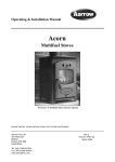
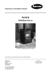
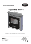
Operating & Installation Manual Esprit PLEASE RETAIN THIS GUIDE FOR FUTURE REFERENCE BK077 EN 13240:2004+ Amd. A2:2004 Rev 06 August 2010 Part No. AFS1399 10 Congratulations on your choice of a Villager stove. More than 40 years experience has been put into the development of our Villager Esprit stove to ensure ultimate performance and years of trouble free use and enjoyment. Every detail of the stove has been carefully designed and engineered which is why we are so confident in the reliability of our products. Should you have any questions about our Villager Esprit stove, that are not covered by this manual, please contact the Villager retailer in your area, or call our technical support department on 0844 847 5107. All Villager Esprit stoves are approved to European Standard EN 13240 and CE marked.* These appliances listed within this manual have been approved by HETAS Ltd as an intermittent operating appliance for burning wood only.* *NOTE : Only applicable to Esprit 8 model. Copyright 2010 Arada Ltd This booklet has copyright and may not be copied in whole, or part, or used for any purpose other than that for which it is supplied without express written consent from Arada Ltd PLEASE NOTE— Arada has a policy of continuous product development and therefore we reserve the right to amend the specification without prior notice. Due to printing cycles, items or options may be described before they are generally available or after they have ceased, so please check with your retailer or dealer. 2 Villager Esprit Stove Contents Page No. INTRODUCTION Page No. SERVICE & MAINTENANCE Warning Notice 4 Annual Maintenance 19 Safety Notices 5 Cleaning 19 The Principle Of The Stove 5 Chimney Sweeping 19 6-7 Door Glass 19 Data Plate Information 7 Outer Finish 19 Technical data 8 Summer Storage / Non Usage 20 Adjusting The Main Door 20 Check List INSTALLATION General Precautions 9 Fuel Retaining - inspection 20 Asbestos 9 Main Fire Door Rope Replacement 21 Handling 9 Fire Door Glass Replacement 21-22 Hearth 9 Primary Air Inlet 21 Combustible Materials 9 Service Record 23 Air For Combustion 9 OPERATING INSTRUCTION Roping Guide For Flue Outlet & Hot Plate 10 Fitting The Flue Outlet & Hotplate 10 Sealing The Terminals 10 Flues & Chimneys 11-14 Firebox Liner Panels 15-16 Adjusting The Self Levelling Feet 17 Final Check 17 Building Control Consent Checklist 18 Lighting The Fire 24 Burning Wood 25 Reduced Burning 25 Extended Burning 26 Safety Warning 26 Over Firing & Chimney Fires 26 Ash Removal 26 Air Inlet Controls (Primary/Air wash) 27 Multi Purpose Operating Tool (Empty The Ash Pan/ Air Wash / Primary Control Knob) 28 Main Fire Door Handle 29 OPTIONAL EXTRA/ACCESSORIES 30 SPARE PARTS LIST 31-33 GUARANTEE 34-35 FACTORY CHECK LIST Villager Esprit Stove 36 3 WARNING IT IS A LEGAL REQUIREMENT THAT THE INSTALLATION OF ALL NEW OR REPLACEMENT, WOOD OR SOLIDFUEL HEATING APPLIANCES ARE REQUIRED TO OBTAIN BUILDING CONTROL APPROVAL FROM YOUR LOCAL AUTHORITY OR THE INSTALLATION WORK MUST BE CARRIED OUT THROUGH A GOVERNMENT APPROVED COMPETENT PERSONS SCHEME SUCH AS OPERATED BY HETAS. IF IN DOUBT, CONTACT HETAS LIMITED TELEPHONE NUMBER : 0845 634 5626 www.hetas.co.uk THIS STOVE MUST NOT BE CONNECTED TO A SHARED FLUE SYSTEM TO ALL USERS PETROLEUM COKE SOME OF WHOSE BRAND NAMES ARE „CALCO’, ‘PETROCOKE’ AND ‘WONDERCO’ MUST NOT BE BURNED IN THIS APPLIANCE BITUMINOUS HOUSE COAL SHOULD NEVER BE USED IN YOUR STOVE TO USE THESE FUELS WILL INVALIDATE THE APPLIANCE GUARANTEE. IF IN DOUBT CONTACT THE SOLID FUEL ASSOCIATION TELEPHONE NUMBER 0845 601 4406 www.solidfuel.co.uk 4 Villager Esprit Stove INTRODUCTION SAFETY THE PRINCIPLE OF THE STOVE A fireguard conforming to BS 8423:2002 should be used in the presence of children and old or infirm people. Please note, this appliance should be used with the fire door closed at all times except when re-fuelling or de-ashing. Your Villager stove is built to the highest standard of craftsmanship using the best materials and the most modern equipment available. It is a highly efficient and sophisticated piece of machinery and when properly installed and operated it should provide a lifetime of heating satisfaction. Do not use aerosol sprays or any other flammable materials near the appliance under fire. Do not fit an extractor fan in the same room as the appliance. Fire cement is caustic, hand and eye protection should always be worn, prolonged contact with the skin should be avoided. Arada Ltd will not be responsible for any consequential or incidental loss or injury however caused. Before continuing any further, with the installation of this appliance please read the following guide to manual handling. Always obtain assistance when lifting the Safety is the most important consideration when installing your fire. If not properly installed and operated a house fire may result. Installation must comply with the Building Regulations and conform to all safety standards. Villager produce a variety of appliances ranging in physical size and heat output all with traditional style features and appearance. The fire door is fitted with a special high temperature ceramic glass panel through which the fire can be viewed. The stove is lined with firebricks or heat reflective panels which ensure complete combustion and provide a good heat store to even out fluctuations in burning. appliance When lifting always keep your back straight, bend your legs not your back Avoid twisting at the waist. It is better to reposition your feet. Avoid upper body / top heavy bending. Do not lean forwards or sideways when handling the fire Always grip with the palms of your hands do not use your fingertips for support Always keep the stove as close to the body as possible as this will minimise the cantilever action. Use gloves to provide additional grip. Villager Esprit Stove An internal throat plate produces turbulence to encourage secondary combustion and direct the flue gas around the whole upper firebox before allowing it to escape up the chimney. Most, Villager stoves are fitted with an „air wash‟ so called because it provides a curtain of high speed preheated air behind the glass to help keep it clean and provide secondary air / over draught. The provision of two inlets on all stoves gives a wide range of primary / secondary air, under draught / over draught combinations. The optimum setting will only be established by experience in firing the appliance, and will depend on the fuel, the position of the appliance in the house, and conditions of the chimney etc. 5 CHECK LIST Inside the appliance body you should find the following: Part Description & Visual Aid Esprit Esprit Esprit Esprit 4kw 6kw 8kw 10kw 1 1 1 1 1 1 1 1 1 0 1 0 0 1 0 1 1, ( 4" ) 1, ( 5" ) 1, ( 5" ) 1, ( 5" ) 1, ( 4" ) 1, ( 5" ) 1, ( 5" ) 1, ( 5" ) 1 1 1 1 1 1 1 1 1 1 1 1 (not to scale) 1. Fuel Retainer 2. Wood Burning Tray 3. Standard style Throat Plate 4. EGD style Throat Plate 5. Flue Spigot 6. Hot Plate 7. Ash Pan 8. Operating Tool 9. Instruction Manual 6 Villager Esprit Stove CHECK LIST Inside the appliance you should find the following : Esprit Esprit Esprit Esprit 4kw 6kw 8kw 10kw 9. Side Liners 2 2 2 2 10. Rear Liners 1 1 2 2 11. Stove Glove 1 1 1 1 1 1 1 1 Description & Visual Aid (not to scale) 12. Self Adhesive Sealing Rope (High Temperature) 1.3 Mtrs ADDENDUM TO ESPRIT INSTALLATION INSTRUCTIONS OCT 09 The parts list shows a 1.3m length of self adhesive rope, and later in the instructions there are details of attaching this rope to the flue spigot and the flue blanking plate please ignore these references as they do not apply to stoves currently in production. ARADA Data Plate Information Please Note- The Esprit stove is fitted with a data plate located at the left hand side, towards the rear of the stove. The plate contains important information and must be observed when installing the stove. Data Plate Location Villager Esprit Stove 7 TECHNICAL DATA Esprit Wood Esprit Wood Esprit Wood Esprit Wood 4kw 6kw 8kw 10kw 4 6 8 10 Efficiency Nett (%) 77.7* 72.1* 80.4 75.8* Mean Flue Gas Temperature (°C) 263* 307* 290 335* Mean CO Emission @ 13% O2 (%) 0.61* 0.47* 0.52 0.44* Flue Mass Gas Flow (g/s) NA NA 5.2 NA Minimum Distance to Combustible materials (mm) NA NA Side = 700 Rear = 850 NA Height (mm) 508 520 560 575 Width (mm) Across Canopy 484 540 608 695 Depth (mm) (Inc. Handle) 363 368 355 372 Height To Centre Of Rear Flue (mm) 414 414 449 464 Depth From Back To Flue Centre (mm) 98 112 110 110 Flue Diameter (mm) 102(4”) 127(5”) 127 (5”) 127 (5”) Weight Packed (Kg) 66.5 77 87 133 Weight Nett (Kg) 62.5 73 82 128 Ideal Log Length (mm) 325 350 400 475 TECHNICAL DATA Nominal Heat Output (Kw) Note: Figures shown with an asterix are in house testing results. 8 Villager Esprit Stove INSTALLATION GENERAL PRECAUTIONS HEARTH Note : All local regulations, including those referring to National and European standards need to be complied with, when installing the appliance. The Building Regulations for England and Wales 2000 ref Approved Document J 2002 edition (issued by the DTLR). The Building Standards (Scotland) (Consolidation) Regulations. Detailed recommendations for installation of appliances, chimneys and flues are outlined in the current issue of the following British Standards : BS6461, BS8303 & BS4543. The stove shall be installed on a floor with adequate load bearing capacity. If the existing construction does not meet this prerequisite, suitable measures (e.g.: load distributing plate) should be taken to achieve it. Ideally, the appliance should stand on a constructional hearth of non-combustible materials not less than 125mm (5”) thick conforming to Building Regulations. Dimensions of the hearth should project at least 300mm (12”) forward of the front of the appliance and 150mm (6”) at the sides. The surface of the hearth should be free of combustible materials. In most buildings with solid concrete or stone floors, the requirement will be met by the floor itself, but mark the hearth to ensure floor coverings are kept well away or use different levels to mark the hearth perimeter. Any Manufacturer’s Instructions must not be taken as overriding statutory requirements. Before any installation work is undertaken consideration must be given to the Health and Safety at Work Act 1974. Safe working practices should be followed at all times. COMBUSTIBLE MATERIALS During installation ensure that adequate precautions are taken to avoid unnecessary risk to yourself or any householder. In particular the danger from caustic nature of the fire cement should be avoided by using these accepted methods : Wear gloves when handling fire cement Wear goggles when chiselling or looking up chimneys. Make sure that Building Regulations are adhered to during installation along with any local by-laws. In the case of heating systems make sure that the pipe work is correctly bonded to ensure electrical earth continuity. Please view the technical data (see page 8) and observe the minimum distance to combustible materials, which is applicable to your stove model. Ideally, adjacent walls should be of suitable non combustible construction, preferably brickwork. In large fireplaces take care that any supporting beam is protected by a 13mm (0.5”) sheet of Masterboard or Superlux spaced 13mm (0.5”) off the surface with strips of non combustible material. Make sure that there is a gap between an un-insulated flue system and any combustible material. This gap must be at least 3X the outside diameter of the flue pipe, or 1.5X the flue diameter to non combustible surfaces. See illustration on page 13. ASBESTOS AIR FOR COMBUSTION All Villager stoves contain no asbestos in their manufacture or construction. If there is a possibility of disturbing any asbestos in the course of installation, then please seek specialist guidance and use appropriate protective equipment. HANDLING The safe handling guidelines are set out on page 5 of this manual, to make movement easier, internal fittings, fuel retainers, grates, firebox liners, flue outlets, hot plates, throat plates etc, can be removed. Care should be taken to make sure that the hinges are not damaged during installation. Villager Esprit Stove There must always be a permanent means of providing air for combustion into the room in which the stove is installed. A permanent vent with a total free area of at least 550mm2 for every KW rated above 5KW should be connected directly to the outside air or to an adjacent room which itself has a permanent vent of the same size direct to the outside air. The positioning of any air vent must be so, that it cannot be liable to blockage or obstruction. Please note : The fitting of an extractor fan to either of these rooms is not permitted. 9 INSTALLATION See addendum on page 7 ROPING GUIDE FOR FLUE OUTLET AND HOT PLATE Joint Overlap All Villager hot plates and spigots are manufactured with a rope groove to accept our high temperature self adhesive sealing rope supplied. This eliminates the need for messy and caustic fire cement, and allows for easy removal for inspection and cleaning, without the accompanying re-sealing mess associated with fire cement. Fig. 2. Correct Roped Hot Plate To seal the hot plate and spigot proceed as follows: FITTING THE FLUE OUTLET AND HOT PLATE 1)The self adhesive sealing rope for the hot plate and spigot is supplied in a single length of 1300mm and needs to be cut in half to begin with. Take the flue spigot and lock into place by rotating anti-clockwise and tighten by tapping with a block of wood and mallet from inside of the appliance. Similarly, fit the hot plate (blanking plate) to the unused opening. Place appliance on the hearth and make sure that it is level and does not rock. Connect the chimney ensuring all joints are sealed with fire cement. 2) Each length of approximately 650mm should be fitted into the groove on the mating face of the hot plate or spigot. See Fig. 1. Flue Pipe Inside Outer Spigot Fig. 1. Apply Rope To Groove 3) Start by removing a small section of the adhesive backing paper (approx. 25mm) and remove the remaining backing paper as you proceeded. Fig. 3. Flue & Spigot Fitting 4) Begin at the rope overlap point, mid way between the securing lugs and work your way around the groove making sure the rope is pressed accurately and firmly into the groove. Finish the rope approximately 10mm past the start point. Note : The flue pipe must be fitted inside the outlet spigot. Failure to do so could result in the spillage of condensation running down the flue. 5) If the rope is allowed to ride up the side of the receiving groove, rather than sitting squarely, in the middle, it will impede the fitting of the hot plate / spigot and may lead to leaks. See Fig. 2. If an add in boiler is not to be fitted, please ensure that the two partially cut circular terminals (located on the rear of the appliance) are sealed with fire cement, and thus preventing surplus air entering the firebox, resulting in less efficiency and poor fuel consumption. 6) Finally press round the sealing rope with a steel rule or similar device, to ensure adhesion is even. Repeat for the remaining casting. 10 SEALING OF TERMINALS Villager Esprit Stove INSTALLATION FLUES AND CHIMNEYS The flue draw is critical on any installation and should be checked to ensure that it matches what is specified. If it is higher than recommended, provision must be made to correct the over draw. The draw can vary in different weather conditions and the customer should be made aware of this. Failure to correct an over-drawing flue will invalidate the warranty. Please remember that chimney draught is dependent on four main factors : Flue gas temperature Flue height Flue size Flue terminal The stove must be connected to a suitable and efficient flue that products of combustion (fumes) from the stove are expelled to the outside air. To ensure a good up draught it is important that the flue gases are kept warm and that the flue size suits the stove. The termination of the outlet at the top of the flue also needs to comply with Building Regulations. The minimum effective height of the flue must be at least 4.5 metres from the top of the stove to the top of the flue outlet. When warm the flue draught should be between 0.1 to 0.2 mb. A chimney may comply with regulations but still be subject to down draught and similar problems. A chimney terminating above the ridge level is generally less likely to suffer such problems. If a new chimney is being provided it should fully comply with the relevant Building Regulations that specify the requirements for solid fuel burning installations. Suitable types of chimney include the following : Masonry Chimney : Built with clay or concrete liners, or a chimney block system meeting Building Regulations. These types of chimney should be installed in accordance with the Building Regulations and BS 6461:Part 1. Factory Made Insulated Chimney : Complying with BS 4543:Part 2 (often called “Class 1 prefabricated metal chimney”). These types of chimney should be installed in accordance with Building Regulations and BS 7566: Parts 1 to 4. Villager Esprit Stove Due to the gradual introduction of Europe Chimney Standards chimneys will be specified according to their performance designation as defined in BS EN 1443 that covers the General Requirements for chimneys. The minimum performance designation required for use with solid fuel burning stoves is T450 N2 S D3. The flue and chimney installation must be carefully checked by a competent person before fitting the stove to ensure it is suitable and will work safely. If the chimney is old (ie: built of brick or stone without a liner) or being opened up for reuse additional checks and smoke testing a described in Appendix E of the Approved Document J 2002 Edition should also be carried out to ensure the flue and chimney are good operating condition. If the flue size is more than 225mm (9”) diameter or 200mm (8”) X 200mm (8”) square, a suitable lining of 150mm (6”) diameter should be fitted, or if the flue length is over 5.5 metres one size larger than the appliance outlet should be fitted. This should be a double skin stainless steel flexible liner that is independently certified for use with solid fuel. Details of suitable linings for use with wood & solid fuel are given in the Official HETAS guide that can be viewed on their website at www.hetas.co.uk. It is also important that suitable flue pipe complying with the Building Regulations is used to connect the stove to the flue in the chimney and that suitable access is provided into the flue for regular inspection and sweeping of the flue ways. The installer should comply with Building Regulations requirements in respect of providing a Notice Plate giving details on the chimney, flue lining, hearth and fireplace installation. Approved Document J of the Building Regulations for England & Wales is available from The Stationary Bookshops and can also be viewed at the ODPM website at www.safety.odpm.gov.uk/bregs/brads.htm. Details on the relevant Building Regulations and BS British Standards are given in the “ General Precautions” section of these instructions. Chimneys should be as straight as possible. Horizontal runs should be avoided except where 11 INSTALLATION the rear outlet of the appliance is used, in which case the horizontal section should not exceed 150mm (6”) in length. If the stove appears to be working hard but produces very little output to the room it is likely that excess draw is present in the chimney, and that heat is being sucked out of the appliance and up the chimney. If this is the case we recommend the fitting of a draught stabiliser in preference to a flue damper, in the interest of safety and efficiency. FOR ALL APPLIANCES Access for cleaning the flue should be incorporated in the system other than through the appliance (eg: a soot door or access through register plate). Purpose made soot doors and inspection lengths are available from manufacturers of all systems. Ensure that the whole length of the flue can be reached from the soot door. Note: if the appliance is fitted with a draught stabiliser or if one is fitted to the flue pipe or chimney in the same room as the appliance, then the permanent air entry opening (or Openings) should be increased by 300 mm2 for each KW of rated output. For advice on flues and chimneys contact: NACE (National Association of Chimney Engineers) Telephone : 01526 322 555 www.nace.org.uk OR NACS (National Association of Chimney Sweeps) Telephone : 01785 811732 www.chimneyworks.co.uk OR HETAS (Official Body To Approve Solidfuel Domestic Heating Appliances) Telephone : 0845 6345626 www.hetas.co.uk 12 Villager Esprit Stove INSTALLATION NOTE - Under no circumstances should this appliance be connected to a shared flue system, that serves any other heating appliance. Minimum 150mm (6”) Diameter Flue Maximum 150mm (6”) Horizontal Flue Section Soot Door Fire Retardant Rope Packing Maximum 100mm (4”) Brick Up Aperture Fill Void TYPICAL REAR FLUE OUTLET (as per BS 8303-1) PLAN VIEW OF REGISTER PLATE AND CLEARANCES FOR NON INSULATED FLUES (Plan View Of Steel Register Plate, 1.5mm Thick Minimum ) Villager Esprit Stove 13 INSTALLATION Typical Metal Insulated Chimney System Installed To The Chimney Manufactures Instructions In Compliance With Building Regulations And BS 7566 Part 1 to 4 Non Combustible Register Plate. Minimum 1.5mm Thick Steel. TYPICAL TOP FLUE OUTLET (as per BS 8303-1) 14 Villager Esprit Stove INSTALLATION FIREBOX LINER PANELS The Villager Esprit stove use firebox liner panels to the sides and back. The standard style throat plate sits on top of the sides and rest on the top surface of the tertiary air inlet. These should come fitted to your stove, if however they are not, proceed as follows to fit them. Open the main fire door. Remove the fuel retainer, by lifting both ends free of the side landings and diagonally rotating the part through the door aperture. Remove the wood burning tray Set the small liner(s) into the back of the firebox, below the tertiary air bar. Insert the Throat plate (Standard style only) into the stove and manoeuvre into position with the back lip sat onto the tertiary air bar. Holding the throat plate (Standard style only) up as high as possible, Insert the side liner panels. (See Fig. 7) these go in front of the rear liners. Allow the throat plate to drop back down onto the side liners as shown in fig.8a Ensure the side liner retaining lip is correctly positioned as detailed in fig.8b Replace the wood burning tray and front fuel retainer. Tertiary Air Bar Side Liner Rear Liner Fig. 6. Liners Inserted Throat Plate Fig. 7. Liners & Throat Plate Correctly Fitted Note: Neither the rear firebox liners nor the side firebox liners are ‘handed’, both faces are suitable for direct contact with the fire bed. Note : Cracking of the liner panels does not effect efficiency. Fig 8a Fitting of the EGD Style Throat Plate If your stove is supplied with the EGD style throat plate (ie a 6 or 10 kw model) the EGD throat plate does not sit on or support the side liners, and does not conform to the detail shown in Fig.8a. Fig. 8b Overall View Of Liners & Standard Style Throat Plate Assembly (Not EGD style) Villager Esprit Stove For fitting instructions for the EGD style throat plate please turn to page 16 15 INSTALLATION Fitting of the EGD ( Exhaust Gas Diversion) Style Throat Plate & Liners The 6 and 10kw models of the Esprit stove is supplied with the EGD style throat plate ( See fig. a ) not the standard style as supplied with the 4 and 8kw stoves. The liner set is installed first as follows: Open the main fire door. Remove the fuel retainer, by lifting both ends free of the side landings and diagonally rotating the part through the door aperture. Insert the side liner panels, these go in behind the rear liner(s) ends and the ends of the tertiary air bar, one each side of the stove. (See Fig. b) Set the small liner(s) into the back of the firebox, below the tertiary air bar. These also retain the side liners in position. Insert the EGD throat plate into the stove and manoeuvre into position with the location lugs sit onto the tertiary air bar location holes and the liner retaining tab against the rear liner(s) (See fig. c) Allow the EGD throat plate to drop forward to rest on the air wash inner cover (within the inside of the stove body) at the top of the stove. See fig c cut away drawing. Replace front fuel retainer. Tertiary Air Bar Side Liner Rear Liner(s) Fig. b Rear liner retaining tab Location lugs to sit in tertiary air bar location holes Fig. c Fig. a EGD in correct position resting on inner airwash cover 16 Villager Esprit Stove INSTALLATION ADJUSTING THE SELF LEVELLING FEET FINAL CHECK LIST The Villager Esprit stove is equipped with adjustable rear levelling feet, these are ideal for use, where the hearth surface is not flat or level. Before handing over the installation to the customer it is requirement under Document J the appliance is lit and the functioning of the chimney system is checked for satisfactory operation. Adjustment is as follows : Be sure that the chimney is operating and ALL smoke and fumes are vented to the atmosphere through the chimney terminal. On the rear leg of the stove, loosen the pozi screw, and rotate the inner „cam‟ shaped levelling foot until this touches the hearth. (see fig. 10.) Check all joints and seals. Clean the outside of the appliance to prevent any stains becoming burnt on. Re-tighten the pozi screw. Check the stove is level with a spirit level. Check the flue draught which should read 1 - 2mm water gauge, or 0.1- 0.2 mbar. Repeat for the other rear leg. If Building Control Consent route is being sought please complete the check list on page 18. For a registered Competent Persons Scheme, such as HETAS, please complete the Certificate Of Compliance, which is used for checking and reporting the installation as imposed by the Government Explain the controls and operation of the appliance to the customer. Position the stove on the hearth into its final resting place, ensuring room for the flue connections etc. The following details must be checked and completed in full by the installer at the time of installation. Please answer all questions as fully as possible. Arada Ltd cannot be held responsible for the chimney or installation problems. Fig. 10. Adjusting The Rear Feet Villager Esprit Stove 17 INSTALLATION BUILDING CONTROL CONSENT CHECKLIST Hearths, Fireplaces, Flues and chimneys This checklist is to ensure heaths, fireplaces, flues and chimneys are satisfactory, and show what you have done to comply with the requirements of the Building Regulations 2000 approved Document J 2002 1. Building address where work has been carried out …………………………………………………………………………….... …………………………………………………………………………………………………………………………. 2. Identification of hearth, fireplace chimney or flue 3. Firing capability: solid fuel / gas /. 4. Intended type of appliance. State model and output. 5. Ventilation provision for the appliance: State type and area of permanently open vents. 6. Chimney or flue construction a, State the type or make and whether new or existing b, Internal flue size (and equivalent height, where calculated natural draught gas appliances only) c, If clay or concrete flue liners used confirm that they are correctly jointed with socket end uppermost and state jointing materials used. d, If an existing chimney has been refurbished with a new Liner, Type and make of liner fitted. e, Details of flue outlet terminal and diagram reference. Outlet Details: / Complies with: f, Number and angle of bends g, Provision for cleaning and recommended frequency. 7. Hearth. Form of construction, new or existing? 8. Inspection and testing after completion Test carried out by: Test and results Flue Inspection Visual Sweeping Coring ball Smoke Appliance (where included) spillage I/We the undersigned confirm that the above details are correct. In my opinion, these works comply with the relevant requirements in part J of Schedule 1 of the Building regulations. Print name and title…………………………………………………………………..Profession………………………………….. Capacity……………………………………………………………………………...Telephone No. …………………………….. Address………………………………………………………………………………………………..Postcode………………….. Signed………………………………………………………………………………..Date………………………………………... Registered member of..(e.g. CORGI, OFTEC, HETAS, NACE, NACS)…………………………………………………………. 18 Villager Esprit Stove SERVICE & MAINTENANCE ANNUAL MAINTENANCE It is important that your appliance is regularly serviced in accordance with these instructions. This should be carried out at least annually by a qualified person and should consist of the following : CLEANING Important; Under some circumstances soot can quickly build up on the throat plate and adjacent areas. The throat plate should be removed and checked monthly, and any debris stripped off. Similarly, clean the upper surface of the firebox. Remove the firebrick linings and throat plate, inspect all rope gaskets on doors, glass etc, and re -order any items that may need replacing from your Villager dealer. With a wire brush clean inside the appliance paying particular attention to the small inlet holes of the air wash on the inside, above the fire door. Sweep the chimney and confirm that it is sound. Examine all joints in the flue pipe etc, and re-seal if necessary. Re-assemble and leave with the air inlet and air wash control about half way open. This will allow a free flow of air through the appliance thus preventing moisture and condensation from building up inside the stove and chimney. CHIMNEY SWEEPING Sweeping should be carried out with an appropriate sized bristle brush and rods to suit chimney size and type. As with all appliances regular sweeping of the flue is essential, to avoid the danger of blockage and the escape of poisonous fumes. Access for cleaning should be incorporated in the chimney (e.g.. Soot door or access through the register plate). Any existing chimney should be swept prior to installation of the appliance, and swept again a second time within one month of regular use after installation to establish frequency of sweeping required. This should be done by a competent person such as a NACS chimney engineer who will provide a Certificate Of Chimney Sweeping. The whole flue way including the outlet must be swept at least twice per burning season. It is important that the flue ways, flue pipe and chimney Villager Esprit Stove be cleaned prior to lighting the fire after a prolonged shut down period. DOOR GLASS The door glass should remain clear during normal burning. However, under certain conditions, such as burning at a low rate , damp wood, or overnight burning, the glass may become somewhat blackened. To remedy this, operate the appliance at a fast rate. Alternatively when the stove is cold, open the door and clean the inside face of the glass with a damp cloth or with glass cleaner (available from fire stockists). A piece of cloth moistened with vinegar and dipped in wood ash (not coal ash) will provide a good soft scourer to remove the soot without scratching the glass. OUTER FINISH The outer finish of the appliance is a durable high temperature paint. It is best cleaned, by brushing down, with a clean shoe brush. Do not allow moisture to remain on the appliance whilst cold or surface rust may form. The high temperature paint should not require attention for some time, depending on use. The hotter the fire burns sooner repainting will be necessary. Aerosol tins of paint are available for complete refurbishing. Before repainting make sure that the fire is out and the stove is cold. Remove the door glass Lightly wire brush, or rub with wire wool, the body of the appliance to remove any loose paint or rust. Mask or remove items such as brass work. Any adjacent brickwork, mantelpiece, hearth etc, should be carefully masked for quite a distance around the appliance. This precaution is to prevent discolouration of the surrounding brickwork or wall paper etc. Re-spray in a well ventilated area, avoid breathing the vapour. Refer to safety instructions on paint cans. When the paint is dry refit the door glass & any other parts previously removed. Leave the appliance for eight hours before lighting a fire. Burn slowly for the first four hours, then build up heat slowly to gradually cure paint. Note: Use genuine Villager touch up spray as some paints interact. This could ruin the finish and invalidate the guarantee. 19 SERVICE & MAINTENANCE SUMMER STORAGE / NON USAGE Please ensure that your stove is left clean and moving components are well lubricated for the summer months (during periods of prolonged non use). If possible store the throat plate outside of the stove, check all moveable components, at regular intervals, to ensure they are moving freely. Allow air movement through the stove, by opening the air wash and primary air inlet (s) controls to about half way open or leave the door ajar. This will allow a free flow of air through the appliance thus preventing moisture and condensation forming inside the stove and chimney. This preventative maintenance will ensure your stove stays in the best condition for the coming winter months. FUEL RETAINER —INSPECTION A curved fuel retainer is supplied with the stove. See Fig 11. The fuel retainer is handed and will only fit in one way round. Fit the retainer with the curve outer most following the stove body curvature. Periodically check for any heat distortion of this part and replace as necessary. Please Note : This operation should only be carried out when the appliance is unlit and cold. Fig 11 Fuel retainer ADJUSTING THE MAIN DOOR Once the appliance has been under fire for a period of time the fire door may appear to have moved out of alignment with relation to the door aperture or catch. This is quite normal and due to the settling of the casting. Note the notch indicating the left hand end of the fuel retainer. If the fire door needs to be raised, please follow : When the appliance is cold, open the fire door so that it is at right angles to the front of the stove. Lift the fire door up off the hinges complete with the hinge pins. Place one washer on the top and bottom hinge plates, making sure the centre holes in the washer, line up with the holes in the hinge plates welded to the body. Carefully, replace the door casting on top of the washers (without moving the shim washers). Push the hinge pins, through the door castings and hinge plate. Check the operation of the door catch. 20 Villager Esprit Stove SERVICE & MAINTENANCE FIRE DOOR ROPE REPLACEMENT FIRE DOOR GLASS REPLACEMENT Periodically, visually check over the fire door rope seal for any damage, cuts or tears and any detached sections. The rope gasket can be replaced, using the universal rope kit (see spare parts guide Page 32), please follow the instructions below : In the event of the door glass being broken it can easily be replaced. Please follow : Ensure the appliance is cold. Lift the door off the appliance and lay onto a flat surface with the rear face upwards. Carefully remove the old rope gasket and old adhesive. Take note of the layout of the old rope seal. Ensure no traces of the old adhesive or rust / flaky paint is present, as this will result in a unsound joint. Apply the rope adhesive following the instructions on the bottle. Press the rope gasket into the channel on the rear of the door casting, following the same layout as the old rope seal. See Fig. 12. Just before the final end, cut the rope seal to length and glue into position. The main fire door should be lifted off the hinges so that the operations can be carried out on a work bench or similar level surface. Unscrew the four bolts securing the glass clips and remove, both clips and fixings. It may be necessary to soak the fixings in WD40 to aid removal. Carefully remove any pieces of broken glass, and sealing gasket, wearing suitable gloves as protection. Take note of the position and joint of the rope gasket. Replace the glass rope gasket; start at the bottom of the window, centrally, push the adhesive side of the rope into the groove on the rear of the casting. Gradually work your way around until the end of the rope meets. See Fig. 13. Re-seat the new glass, ensuring the glass sits flat against the gasket, the glass should sit with an equal gap between the glass and the top and bottom cast pads. See Fig. 14. Replace the four retaining clips and fixing bolts. Do not over tighten the fixings as damage may occur to the glass. ONLY USE HAND TOOLS TO TIGHTEN FIXINGS. See Fig.15. Refit the door assembly back onto the stove; carefully lift the door over the hinge and slot into place. Allow 30 minutes, before refitting the door to the appliance. Rope Gasket Joint here Fig. 12. Rope Replacement Fig. 13. Lining Up Gasket Rope Villager Esprit Stove 21 SERVICE & MAINTENANCE Please Note—This should be carried out when the fire is cold and unlit. Fig. 14. Positioning The Glass Ensure this gap is equal top and bottom, approx 2.5mm DOOR PRIMARY AIR INLET A yearly check is required to inspect the primary air inlet assembly, located on the rear of the main fire door. Once the appliance is unlit and cold, open the main fire door . Clean off any ash or tar residue from the inside face of the rear of the door. Working from the front, unscrew the control knob, whilst holding the slider on the inside. Withdraw the slider and inspect / clean the mating face and the inside face of the door casting. Replace the slider if damaged or warped Reverse the instructions for the refitting. Approx 2.5mm The glass clips should be hand tightened only Fig. 16. Inspection Of The Primary Slider Fig. 15. Tightening The Glass Clip USE ONLY HAND TOOLS TO TIGHTEN THE GLASS FIXINGS 22 Villager Esprit Stove SERVICE & MAINTENANCE Service Record Date of Visit Company Work Carried Out Signature Should you have any questions about your Villager Esprit stove that are not covered in this manual please contact your Villager dealer. Please keep all repair receipts safely. Please ensure you have this manual available when an engineer visits so they can complete the service record chart. Villager Esprit Stove 23 OPERATING INSTRUCTIONS FUEL TYPES SAFETY NOTICE The most efficient use of this appliance is with the fire door(s) closed at all times, apart from re-fuelling (when alight) or cleaning (when cold). NEVER leave the appliance unattended for an extended length of time with the door(s) open. If this is the case, a spark guard must be used and the operating efficiency of the appliance will decrease. WOOD— Any type of wood is suitable provided it is well seasoned and has a moisture content below 20%. This usually implies that the timber has been suitably stored to allow moisture to evaporate for at least nine months in the case of soft woods, and at least eighteen months in the case of hard wood. We recommend that for general burning, wood should be split into logs of no more than 100mm (4”) diameter. WARNING : wet wood must not be used as this will greatly contribute to the creation of tar and creosote which may, in extreme cases, run down the chimney in liquid form. This will seriously damage both the chimney and the appliance, and increase the risk of a chimney fire. Please Note : If you have sticky tar inside the appliance or chimney your wood is ‘Green’ or too wet. Please Note : The burn classification for all appliances in these instructions are classed as intermittent use. Recommended Reading ; “Wood as a fuel” available from the Forestry Commission. PAPER– Paper will burn successfully. Burn dry paper only or chimney damage will occur. WARNING : NEVER BURN PLASTICS OR HOUSEHOLD WASTE IN YOUR STOVE. WARNING : NEVER BURN LIQUID FUELS IN YOUR STOVE. 24 PLEASE CONTACT : The Manufacturer For Further Details & Advice On The Use Of Other Fuels. Do not use petroleum based solid products such as Calco or Petrocoke. To do so will INVALIDATE the appliance Guarantee. For additional further advise on fuels, please refer to HETAS, Tel 0845 634 5625 or www.hetas.co.uk and or Solid Fuel Association, Tel 0845 601 4406 or www.solid-fuel.co.uk HETAS Approval only covers the use of wood on the appliance and does not cover the use of other fuels either alone or mixed with other fuels, nor does it cover instructions for uses of other fuels. LIGHTING THE FIRE Prior to lighting the stove for the first time, check with the installer that : Installation and all building work is complete. The chimney is sound and has been swept and is free from obstruction. Adequate provision for combustion air has been made, i.e. a permanent vent of at least 550mm sq per KW of rated output above 5KW, is fitted in the room in which the appliance is installed. Please note page 10, if a flue stabiliser is fitted to the flue. That Building Regulations and any local by laws have been followed during installation. See installation section of this manual. All firebox liner panels and throat plate are in place. That the chimney draw has been checked and is within specification. With the chimney warm, the draught should be between 1-2 mm water gauge or 0.1 to 0.2 mbar. WARNING : An over drawing chimney can cause over firing, resulting in damage to the appliance. ENSURE THAT YOU HAVE READ & UNDERSTOOD THESE INSTRUCTIONS BEFORE LIGHTING THE FIRE. ALWAYS WEAR SUITABLE PROTECTIVE FIRE GLOVES WHEN REFUELLING YOUR STOVE. Villager Esprit Stove OPERATING INSTRUCTIONS BURNING WOOD REDUCED BURNING Set the fire; by using rolled up newspaper and lay a layer of dry kindling wood on top of this. Please Note : Classification of these appliances are for intermittent use. Use 2 or 3 fire lighters to light the kindling. Lower or reduced burn rates are possible by reducing the primary and secondary (air wash) air inlet controls to a lower setting. Please note if both controls are set on the minimum settings the appliance will be starved of air and die down. Set the primary air and air wash controls to fully open position. See page 27. After the kindling has caught light, leave the fire door ajar by about 20mm. This will aid flue draw. The flue draw should be established after 5 minutes and the kindling will burnt down to form an ember bed. Carefully load the stove with well seasoned wood and close the fire door. After 10 to 15 minutes, regulate the air wash control, typically reduce to approximately half way. Similarly, reduce the primary air control, to the off position (-) as generally no air from below the grate is required when burning wood. Please Note : The high temperature paint acquires durability by being “cured” during the initial firings of the appliance. It will give off fumes which are non toxic, but certain persons may find they have an unpleasant or irritant effect. Ensure that the surrounding area is well ventilated during this time. WARNING : when wood is burnt slowly in a closed appliance, it produces moisture and tar, which will create condensation and deposits in the chimney. This effect can be minimised by burning hard for a short period, 15 to 20 minutes, twice a day. Please Note : To avoid chimney problems your appliance should not be burnt at a reduced burn rate without a period of fast burning. WARNING : Properly installed, with a suitable flue or chimney and operated and maintained, this appliance will not emit fumes into the dwelling. Occasional fumes when de-ashing and re-fuelling may occur. However, persistent fume emission is potentially dangerous and must be investigated by a HETAS registered installer. Stop using the appliance if you smell fumes or see smoke escaping. If fume emission does persist, the following immediate actions should be taken : Open doors and windows to ventilate room. Let the fire die or extinguish and safely dispose of fuel from the appliance. Check for flue or chimney blockage, and clean if required. Seek expert advice from your HETAS registered installer. Do not attempt to re-light the fire until the cause of the fume emission has been identified and corrected. Villager Esprit Stove 25 OPERATING INSTRUCTIONS EXTENDED BURNING OVER FIRING & CHIMNEY FIRES The appliance will burn for extended periods provided Sufficient fuel is placed in the firebox. The air controls are set correctly. DO NOT over fire your appliance. Using flammable liquids or too much wood or firing the stove at maximum for prolonged periods may result in over-firing. If the chimney connector or casing glows red the appliance is being over-fired this may result in a chimney fire. If this occurs : Excess draught is not present in the chimney. Call the Fire Service—Dial The main fire door is closed. Immediately close all of the air inlets to the appliance, to reduce the air supply to the stove. If the fire goes out with un-burnt fuel in the firebox, increase the air inlet openings slightly and vice versa. In the morning, open the air controls fully until the embers begin to glow brightly and place pieces of new fuel on these embers, sufficient to establish a fire. 999 Move items of furniture and combustibles away from the stove, to reduce a risk of fire and to allow access for the fire service. Ensure access to the loft space is available. Evacuate the property. SAFETY WARNING Properly installed, with a suitable flue / chimney, operated and maintained, this appliance will not emit fumes into the dwelling. Occasional fumes when de-ashing and re-fuelling may occur. However, persistent fume emission is potentially dangerous and must be investigated by a HETAS registered installer. STOP USING THE APPLIANCE IF YOU SMELL FUMES OR SEE SMOKE ESCAPING. If fume emission does persist, the following Immediate actions should be taken Open all doors and windows to ventilate the room. Let the fire bed die or extinguish and safely dispose of fuel from the appliance. Check for flue or chimney blockage and clean if required. Seek expert advice from your HETAS registered installer. DO NOT attempt to re-light the appliance until the cause of the fume emission has been identified and corrected. 26 The chimney fire may cause structural damage to the chimney. Do not use the appliance until the chimney and connector have been inspected and any damaged parts have been repaired or replaced. This should be done by a HETAS registered engineer. ASH REMOVAL The appliance will require ash to be removed periodically but an ash bed of approximately 20mm (3/4”) should be maintained. Ash may be removed with a small shovel whilst the fire is still lit by raking the embers of a low fire to one side of the firebox and carefully removing the ash, then repeating the procedure for the other side. Care must be taken not to risk burning of hands or household objects from falling embers. The ash pan should be emptied at least twice a day or when the level of ash reaches the top of the ash pan. When the appliance is burning WOOD, it is acceptable to maintain an ash bed on top of the wood tray, of approximately 20mm (3/4”) without any un-due effect. WARNING : The ash can be very hot. Empty only into a metal container. Even if the ash appears cold, red-hot pieces of ash may be concealed and could easily start a fire or cause an injury. Villager Esprit Stoves OPERATING INSTRUCTIONS AIR INLET CONTROLS The Villager Esprit stove has two air inlet controls. The primary air inlet providing under draught to the base of the fire chamber through the control sliders located in the ash pit door. The air wash system, (secondary air) so called because its pre-heated high speed air, washes across the inner face of the door glass, keeping it clear. This also provides an over draught to the fuel bed. AIR WASH SYSTEM (SECONDARY AIR) The air wash has an internal sliding plate with slots, housed within the main body of the stove, and is located above the fire door. Sliding the control knob to the right as far as it will go, achieves the fully open position, see Fig. 18. Sliding it to the left will shut off the air inlet slots as shown in Fig. 19. PRIMARY AIR Air enters the appliance through the control on the bottom of the fire door. The Villager Esprit has a control knob which slides left to right. Sliding the knob to the Right, (See Fig. 16), will Increase the amount of air intake to the stove. To Decrease or close, push the slider to the left as in Fig. 17. Fig. 18. Air Wash Fully Open Position Fig. 16. Fully Open Position Fig. 19. Air Wash Fully Closed Position Fig. 17. Fully Closed Position Villager Esprit Stove 27 OPERATING INSTRUCTIONS MULTI PURPOSE OPERATING TOOL Your Villager stove is supplied with a multi purpose operating tool, which is used for adjusting the air inlet controls, the removal of the ash pan and opening and closing the main fire door. TO EMPTY THE ASH PAN The Villager Esprit stove is supplied with a unique ash pan. To empty or remove the ash pan, open the main fire door, fit the fork end of the operating tool into the ash pan slots and remove from the ash pit chamber. AIR WASH / PRIMARY CONTROL KNOBS The operating tool can also be used to adjust the primary inlet and air wash control knobs. Use the fork end of the tool, place side onto the knob and push in the desired direction, see Fig. 20. Fig. 21. Operating Tool & Ash pan Empty the ash into a suitable container and replace the ash pan into the stove, withdraw the operating tool and close the main fire door. Fig. 20. Adjusting Air Wash Controls Fig. 22 Operating Tool & Main Fire Door Handle 28 Villager Esprit Stove OPERATING INSTRUCTIONS MAIN FIRE DOOR HANDLE A stove glove / mitten is supplied with your Villager Esprit stove, this is provided for the operation of the fire door handle and refuelling the appliance while the stove is in use. Care must be taken when opening and closing the fire door as any surrounding areas of the stove will be very hot. WARNING UNDER NO CIRCUMSTANCES SHOULD THIS STOVE BE OPERATED FOR EXTENDED PERIODS WITH THE MAIN FIRE DOOR OPEN. THIS WILL RESULT IN AN OVER FIRING SITUATION AND WILL QUICKLY LEAD TO SEVERE DAMAGE TO THE STOVE AND FLUE SYSTEM. Fig. 23. Supplied Glove WARNING : Never attempt to open the fire door whilst the appliance is in use WITHOUT the use of the stove mitten or suitable gloves, serious injuries may occur. Caution must be given when re-fuelling the appliance, always keep the stove mitten away from naked flames and sparks. Villager Esprit Stove 29 OPTIONAL EXTRA / ACCESSORIES ESPRIT 4kw ESPRIT 6kw ESPRIT 8kw ESPRIT 10kw Floor Fixing Kit AFS 1135 AFS 1135 AFS 1135 AFS 1135 Add In Slab Boiler AIBV018 AIBV019 AIBV016 AIBV017 Additional Stove Glove ( To form one of a pair of gloves *) AFS 1285 AFS 1285 AFS 1285 AFS 1285 Add on canopy HIGH AOCVE4H AOCVE6H AOCVE8H AOCVE10H Add on canopy LOW AOCVE4L AOCVE6L AOCVE8L AOCVE10L Stand STAND VSDE4 STAND VSDE6 STAND VSDE8 STAND VSDE10 Log Store Stand LOG VSDE4 LOG VSDE6 LOG VSDE8 LOG VSDE10 PART DESCRIPTION VISUAL AID ( Not To Scale) NOTE : * Separate instructions are included for all accessories except Stove Glove AFS1285 30 Villager Esprit Stove SPARE PARTS LIST Part No. Esprit 4kw Part No. Esprit 6kw Part No. Esprit 8kw Part No. Esprit 10kw Extended Throat Plate AFS1503 N/A AFS1419 N/A Flue Spigot AFS009A AFS009 AFS009 AFS009 Hot Plate AFS009B AFS010 AFS010 AFS010 Rear Liner AFS1451 AFS1451 AFS1420 AFS1467 Side Liner AFS1420 AFS1206 AFS1069 AFS1069 Liner Set Complete AFS1532 AFS1533 AFS1421 AFS1475 E.G.D. Throat Plate N/A AFS1504 N/A AFS1527 Description Villager Esprit Stove Visual Aid ( Not To Scale ) 31 SPARE PARTS LIST Part No. Esprit 4kw Part No. Esprit 6kw Part No. Esprit 8kw Part No. Esprit 10kw Ash Pan AFS1508 AFS1508 AFS1422 AFS1422 Fuel Retainer AFS1507 AFS1507 AFS1424 AFS1424 Operating Tool AFS008 AFS008 AFS008 AFS008 Replacement Glass Kit AFS1484 AFS1484 AFS1423 AFS1423 Replacement Glass Rope Gasket and Clips AFS1365 AFS1365 AFS1365 AFS1365 Fire Door Rope Kit AFS1474 AFS1474 AFS1474 AFS1474 Replacement O/I Manual AFS1399 AFS1399 AFS1399 AFS1399 Description 32 Visual Aid ( Not To Scale ) Villager Esprit Stove SPARE PARTS LIST Part No. Esprit 4kw Part No. Esprit 6kw Part No. Esprit 8kw Part No. Esprit 10kw Fire Door Complete AFS1530 AFS1530 AFS1425 AFS1425 Fire Door Handle Assembly AFS1427 AFS1427 AFS1427 AFS1427 Hinge & Fixing kit AFS1279 AFS1279 AFS1279 AFS1279 Primary Air Slider AFS1531 AFS1531 AFS1426 AFS1426 Air Wash & Primary Slider Knob AFS1405 AFS1405 AFS1405 AFS1405 Replacement Wood Tray AFS1501 AFS1502 AFS1428 AFS1468 Replacement Tertiary Air Bar & Fixings AFS1510 AFS1509 AFS1432 AFS1465 Replacement Wood Burning Blanking Piece AFS1429 AFS1429 AFS1429 AFS1429 Description Villager Esprit Stove Visual Aid ( Not To Scale ) 33 GUARANTEE Guarantee Once again we would like to thank you for buying a Villager Esprit stove. When you buy a Villager stove, you are not only buying a first class appliance you are buying a commitment from us to look after you and your appliance for as long as you want. If your appliance proves to be defective as a result of faulty materials or workmanship during the guarantee period, we will repair or replace it FREE OF CHARGE as long as the stove has been installed according to this manuals instructions and the Final Installation Check List on page 17 has been completed and signed by a suitably qualified engineer at the time of installation. Your Villager Esprit stove comes with a THREE YEAR GUARANTEE against splitting or cracking of the main body. The main body being defined as the steel outer casing and items fixed immovably to the casing. All other parts are covered by a one year no-quibble parts guarantee. USE OR SPARE PARTS OTHER THAN THOSE SUPPLIED BY VILLAGER WILL INVALIDATE THE APPLIANCE WARRANTY. This guarantee shall not apply to any part that has been altered in any way, or which in our judgment has been subjected to misuse, neglect, accident, abuse and fair wear and tear. ARADA LTD WILL NOT BE RESPONSIBLE FOR ANY CONSEQUENTIAL OR INCIDENTAL LOSS, DAMAGE OR INJURY HOWEVER CAUSED. Items which would be subject to fair wear or tear, firebox liner panels, fuel retainers, throat plate, door rope, door glass, grate or grate bars and gaskets are not covered by the guarantee. However, should you have any problems with your appliance, please contact your Villager stockist who will have the knowledge and facilities to help you. All guarantee periods commence on the date of purchase and are non-transferable. Our guarantee is offered as an additional to your statutory rights. Villager (Arada Ltd), cannot guarantee item which are susceptible to breakage or damage through careless handling, dropping etc., or through misuse of the appliance by over firing, burning petroleum coke, etc. Nor can the guarantee be extend to deterioration of parts through fair wear and tear. Firebox linings, grate bars, fuel retainer, baffle, gasket materials and door glass are therefore not covered by the guarantee. The guarantee is conditional upon the appliance being serviced and checked annually by a qualified heating engineer, with documentation to be retained and produced in the event of a claim being made. Claims are not valid where installation does not conform to appropriate building regulations. The manufactures decision shall be final. 34 Villager Esprit Stove FIREGUARD Guarantee For your peace of mind The Villager THREE YEAR - “FIREGUARD GUARANTEE” for stoves, covers the materials listed in the following schedule, plus construction and workmanship. In the unlikely event of any failure of the components covered by this guarantee, Villager will replace then free of charge to return the stove to its original specification. Labour costs excluded. ITEMS COVERED BY THIS GUARANTEE The complete steel structure of the stove, its manufacture and construction workmanship. ITEMS NOT COVERED BY THIS GUARANTEE The following consumables, an integral part of the stove on installation, are not covered: Door glass, Door Sealing Cord, All Consumable Working Parts IE: The Thermocouple, Piezo Igniter, Loose Coals & Coal Matrix (Gas Products), All Fire Bricks, Log Retainers, Throat Plates, Grate Bars, Spark Guard, Ash Pan, Operating Tool and Ash Carrier. All Boilers carry a 12 month guarantee. In the unlikely event that any of these components are broken on delivery, they will be replaced provided a claim is made within 5 days of delivery. IMPORTANT NOTE The assembly, installation and operation of the stove, because it does not come under our direct control, is not included in this guarantee. You are advised to discuss guarantees on this aspect of the work directly with your stove supplier or approved and accredited installation engineer. The whole of the Villager “FIREGUARD GUARANTEE” is invalid if any part of the stove assembly, installation or operation does not comply with the published instructions supplied with the stove and with all building and gas installation regulations in force at the time of purchase. To validate your guarantee you must retain your receipt as proof of purchase, which we suggest you attach to this guarantee. This guarantee does not effect your statutory rights. Villager Esprit Stove 35 Final Factory Check list Stove Model …………….……………........ Serial No. ………………………………...... Quality / Finish I’ve checked it and its O.K ! Main Door Operation / Sealing Air Wash Operation Primary Air Slider Operation Standard or EGD style Throat Plate Assembled By……………………….. Hot Plate Flue Spigot Outlet Checked by………………………….. Rear Vermiculite Liners x2 Side Vermiculite Liners x2 Fuel Retainer Curved Leg Height Adjusters x2 Ash Pan Stove Operating Tool Self Adhesive Sealing Rope 1.3mtr Installation & Operating Manual Stove Glove Tertiary Air Bar Date of Purchase……………………. Name and Address of Stove Supplier …………………………………………………………….. …………………………………………………………………………………………………………. …………………………………………………………………………………………………………. …………………………………………………………………………………………………………. Arada Ltd The Fire Works Weycroft Avenue Axminster, Devon, EX13 5HU United Kingdom Tel: +44(0)1297 35700 Fax: +44(0)1297 35900 www.villager.co.uk BK077