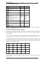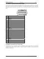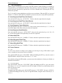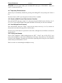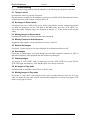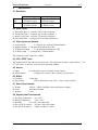
1
Duplex Multiplexers
User Manual
Page 1
Videoswitch
Duplex Multiplexers
User Manual
This manual covers the following Multiplexers:
Monochrome
VSM-24A
VSM-28A
VSM-24
VSM-28
VSM-212
VSM-216
VSM-220
Colour
VCM-24A
VCM-28A
VCM-24
VCM-28
VCM-212
VCM-216
VCM-220
4 Camera Duplex Multiplexer (Desktop)
8 Camera Duplex Multiplexer (Desktop)
4 Camera Duplex Multiplexer (Stackable)
8 Camera Duplex Multiplexer (Stackable)
12 Camera Duplex Multiplexer (Stackable)
16 Camera Duplex Multiplexer (Stackable)
20 Camera Duplex Multiplexer (Stackable)
4 Camera Duplex Multiplexer (Desktop)
8 Camera Duplex Multiplexer (Desktop)
4 Camera Duplex Multiplexer (Stackable)
8 Camera Duplex Multiplexer (Stackable)
12 Camera Duplex Multiplexer (Stackable)
16 Camera Duplex Multiplexer (Stackable)
20 Camera Duplex Multiplexer (Stackable)
Every effort has been made to ensure the accuracy of the information in this manual. However, Videoswitch
assumes no liability for losses incurred as a result of out of date information, errors or omissions. As part of
a policy of continual product improvement, Videoswitch reserves the right to make changes to product
specifications and documentation without notice.
No reproduction of this document or any portion of it is permitted without the specific written permission of
Videoswitch.
This manual relates to multiplexers fitted with software Revision R3.01
Videoswitch is a trading division of Ocean Systems Ltd. ©Ocean Systems Ltd 1999.
Videoswitch
Sales:
01252-851510
Unit 15 Redfields Industrial Park
Other:
01252-851477
Church Crookham
Fax:
01252-851296
Hants GU13 0RD
Email:
[email protected]
____________________________________
Videoswitch
VCM614d.doc
Duplex Multiplexers
England
User Manual
Web:
Page 2
videoswitch.co.uk
____________________________________
Videoswitch
VCM614d.doc
Duplex Multiplexers
User Manual
Page 3
Contents:
1. GETTING STARTED .......................................................................................................................................... 4
1.1 Step 1 - Connecting to Cameras, Monitors, VCR and Mains Supply ....................................................................................................................4
1.2 Step 2 - Step Cable ..................................................................................................................................................................................................4
1.3 Step 3 - Alarms ........................................................................................................................................................................................................4
1.4 Step 4 - Identification of Switches ..........................................................................................................................................................................5
1.5 Step 5 - Time-Lapse Mode Switch (S1)..................................................................................................................................................................5
1.6 Step 6 - Set-up Options Switch (S2) .......................................................................................................................................................................5
1.7 Step 7 - Camera Termination Switches (S3, S4, S5, S6 and S7) ............................................................................................................................5
1.8 Step 8 - SET key options .........................................................................................................................................................................................5
2. OPERATION......................................................................................................................................................... 6
2.1 Record/Play Modes .................................................................................................................................................................................................6
2.2 VCR View Mode.....................................................................................................................................................................................................6
2.3 Display Options .......................................................................................................................................................................................................6
2.4 Auto-Sequence ........................................................................................................................................................................................................7
2.5 System Testing ........................................................................................................................................................................................................7
3. SWITCH OPTIONS ............................................................................................................................................. 8
3.1 Time Lapse Mode Switch (rotary) - with a Step Cable...........................................................................................................................................8
3.2 Time Lapse Mode Switch (rotary) - without a Step Cable......................................................................................................................................9
3.3 Set-up Switch (8-way DIL) ...................................................................................................................................................................................10
3.4 Camera Termination Switches (4-way DIL) .........................................................................................................................................................10
3.5 Interface Connector Pin-out (25-way D-type) ......................................................................................................................................................11
3.6 RS232 Connector Pin-out (3.5mm Jack)...............................................................................................................................................................11
4. SET KEY OPTIONS........................................................................................................................................... 12
4.1 Auto Sequence Dwell Time (Full Screen) ............................................................................................................................................................12
4.2 Auto Sequence Dwell Time (Quad Screen) ..........................................................................................................................................................12
4.3 Auto Sequence Camera Selection .........................................................................................................................................................................12
4.4 Auto Sequence Quad Selection .............................................................................................................................................................................12
4.5 Alarm Hold Time...................................................................................................................................................................................................12
4.6 Alarm Sequence Dwell Time ................................................................................................................................................................................12
4.7 Alarm Relay Hold Time ........................................................................................................................................................................................12
4.8 Covert Cameras .....................................................................................................................................................................................................12
4.9 Temporarily Disable Alarms .................................................................................................................................................................................13
4.10 Quad and Multi Screen Video Interlace Selection..............................................................................................................................................13
4.11 User Defined Record Interval .............................................................................................................................................................................13
4.12 Factory-Set Defaults............................................................................................................................................................................................13
5. TROUBLE-SHOOTING .................................................................................................................................... 14
5.1 Things to check......................................................................................................................................................................................................14
5.2 No Images in Record mode ...................................................................................................................................................................................14
5.3 Missing Images in Record mode ...........................................................................................................................................................................14
5.4 Missing Cameras in Auto Sequence......................................................................................................................................................................14
5.5 Washed Out Images...............................................................................................................................................................................................14
5.6 Dark Images...........................................................................................................................................................................................................14
5.7 Flashing Images.....................................................................................................................................................................................................14
5.8 No Images in Play mode........................................................................................................................................................................................14
5.9 Missing Images in Play mode................................................................................................................................................................................14
6. SPECIFICATIONS............................................................................................................................................. 15
6.1 Resolution..............................................................................................................................................................................................................15
6.2 Dwell Times...........................................................................................................................................................................................................15
6.3 Video Inputs and Outputs......................................................................................................................................................................................15
6.4 VCR “STEP” Input................................................................................................................................................................................................15
6.5 Alarms....................................................................................................................................................................................................................15
6.6 RS232 ....................................................................................................................................................................................................................15
6.7 Power Requirements..............................................................................................................................................................................................15
6.8 Physical and Environmental..................................................................................................................................................................................15
7. SAFETY WARNING.......................................................................................................................................... 16
____________________________________
Videoswitch
VCM614d.doc
Duplex Multiplexers
1.
User Manual
Page 4
Getting Started
1.1 Step 1 - Connecting to Cameras, Monitors, VCR and Mains Supply
Connect the multiplexer to the cameras, monitor(s), VCR and mains supply as illustrated in this
diagram.
Note that an 8-camera multiplexer is used in this example. Other multiplexers differ in the number
and location of the connectors.
Each camera input is provided with two BNC connectors. This allows cameras to be loopedthrough to other equipment. Either connector may be used for input or output.
Note: This is an example only. Refer to the rear panel labelling for specific locations of connectors.
Desktop models do not have loop-through.
1.2 Step 2 - Step Cable
If a step cable is required, connect it between the multiplexer and the VCR as in the diagram above.
Refer to section 3.1 and section 3.2 for details.
1.3 Step 3 - Alarms
If alarms are required, connect these in accordance with the details in section 3.5.
____________________________________
Videoswitch
VCM614d.doc
Duplex Multiplexers
User Manual
Page 5
1.4 Step 4 - Identification of Switches
Identify where the switches are on the underside of the multiplexer as illustrated in this diagram.
A 20-camera multiplexer is used in this example. Other models are similar but have fewer
termination switches.
1.5 Step 5 - Time-Lapse Mode Switch (S1)
Set this switch to suit the time lapse mode of the VCR or to specify whether a step cable is being
used. For example, set to position 4 for 24 time-lapse operation without a step cable. Refer to
section 3.1 and section 3.2 for details.
1.6 Step 6 - Set-up Options Switch (S2)
Set this switch to specify the basic set-up options. In most installations, the default setting of all
sections OFF, will be required. Refer to section 3.3 for details.
1.7 Step 7 - Camera Termination Switches (S3, S4, S5, S6 and S7)
Set these switches ON if camera termination is required. In most installations the default setting of
all sections ON will be required. Refer to section 3.4 for details.
1.8 Step 8 - SET key options
Further options are available by using the SET key in combination with other keys. In many cases it
is not necessary to access these facilities. Refer to section 4 for details.
____________________________________
Videoswitch
VCM614d.doc
Duplex Multiplexers
2.
User Manual
Page 6
Operation
2.1 Record/Play Modes
• If the “PLAY” light is OFF, the multiplexer is in RECORD mode. This mode is used for
recording the camera images onto tape. Make sure that the VCR is also in “RECORD” mode.
• If the “PLAY” light is ON, the multiplexer is in PLAY mode. This mode is used to replay
images from tape. Make sure that the VCR is also in “PLAY” mode.
Press the PLAY key to change mode. To enter PLAY mode, the PLAY key must be pressed for at
least 1 second.
2.2 VCR View Mode
If the “VCR VIEW” light is ON, the multiplexer is in “VCR VIEW” mode.
The “VCR VIEW” mode allows the output of the VCR to be directly viewed. If the VCR and
Multiplexer are both in “RECORD” mode, “VCR VIEW” mode allows the rapidly multiplexed
images to be seen on the Monitor “A”. This provides a confidence check that multiplexing is taking
place and that all cables are correctly connected. It also allows the clock/calendar of the VCR to be
viewed and/or set.
Press the “VCR VIEW” key to change mode.
2.3 Display Options
This table summarises the display options of the different multiplexers:
Multiplexer Models
VSM-24(A)
&
VCM-24(A)
VSM-28(A)
&
VCM-28(A)
VSM-212 & VCM212
VSM-216 & VCM216
VSM-220 & VCM220
Full
Screen
Quad
9
9
9
9
9
9
9
9
9
9
9
9
Dual
Quads
12way
multi
screen
16-way multi
screen
20-way multi
screen
9
9
9
2.3.1 Full Screen Images
A full screen camera image may be view on Monitor “A” in both “RECORD” and “PLAY” modes.
Press one of the camera select keys (identified as 1, 2, 3, 4 etc) to view the full screen image.
2.3.2 Quad Images (4-Camera multiplexers only)
The VCM-24 and VSM-24 multiplexers allow a full screen or a quad to be displayed on monitor
“A”, and a Quad to be displayed on monitor “B”. Press the “1-4” key and hold for 1 second to
display the quad image on Monitor “A”.
____________________________________
Videoswitch
VCM614d.doc
Duplex Multiplexers
User Manual
Page 7
2.3.3 Quad Images (8-Camera multiplexers only)
The VCM-28 and VSM-28 multiplexers allow a full screen or a quad to be displayed on monitor
“A”, and a Quad to be displayed on monitor “B”. A different quad may be selected for each
monitor.
To select a quad for Monitor “A” press the “1-4” or “5-8” key in the “Monitor “A” group of keys
on the front panel.
To select a quad for Monitor “B” press the “1-4” or “5-8” key in the “Monitor “B” group of keys on
the front panel.
2.3.4 Quad/Multi-screen Images (12, 16 and 20 Camera multiplexers only)
These multiplexers allow a full screen or a multi-screen image to be displayed on monitor “A”, and
a multi-screen image to be displayed on monitor “B”. It is not possible to display different multiscreen images on the two monitors.
To select a multi-screen image for Monitor “B”, momentarily press one of the multi-screen select
keys (eg. “1-4”, “5-8” etc).
To select a multi-screen image for Monitor “A”, press one of the multi-screen select keys and keep
pressing it for 1 second.
2.4 Auto-Sequence
The VCM-24(A) and VSM-24(A) have a single “AUTO” key to sequence full screen images.
Other models allow either full screen or quad images may be auto sequenced.
The VCM-28(A) and VSM-28(A) have two “AUTO” keys, one assigned to each monitor.
In the case of the 12, 16 and 20-camera multiplexers, selection is by function rather than monitor:
the two “AUTO” keys are for “FULL SCREEN” and “SPLIT SCREEN” (multi-screen).
To select which cameras or quads are included in the sequence or to change the dwell time, refer to
section 1.8.
2.5 System Testing
It is essential that, during day-to-day use of the equipment, that VCR tapes are played back
regularly to check that the installation is still functioning correctly. This is the only way to
guarantee that no faults have developed in the cabling, cameras, VCR, multiplexer or ancillary
equipment.
____________________________________
Videoswitch
VCM614d.doc
Duplex Multiplexers
3.
User Manual
Page 8
Switch Options
3.1 Time Lapse Mode Switch (rotary) - with a Step Cable
The multiplexer may be used with a “step” cable connected to the VCR. The step cable allows the
multiplexer to detect the time-lapse recording mode of the VCR and configure itself automatically.
If a step cable is being used, the rotary switch (S1) must be set one of two positions:
Rotary
Switch
(S1)
0
1
“Step” Input
No
pull-up
resistor
(default)
With pull-up resistor
3.1.1 Reasons for using a step cable
a) If the required time lapse mode is not available by switch selection.
b) If there is any doubt as to the way in which the VCR samples.
c) If the time lapse mode is regularly altered (e.g. a different mode at weekends).
3.1.2 Configuring the system to use a STEP cable
a) Set the rotary switch (S1) to position 0.
b) Connect the step output (sometimes called “CAM SW”, “SW OUT”, etc.) of the VCR to pin 14
of the 25-way D-type connector on the multiplexer.
c) Set the VCR up to generate a step signal (if this is a menu programmable option). Also select “1
Field” mode (not “Frame”) if this is an option.
3.1.3 Check that the STEP cable is operating properly
a) Put the multiplexer into RECORD mode.
b) Make sure the VCR is in time-lapse RECORD mode (3-hour mode will not produce a pulse from
some makes of VCR).
c) Look at the top right corner of Monitor “A” to see if the correct time lapse mode is being
displayed (allow up to 5 seconds to detect the mode).
3.1.4 If the multiplexer is not detecting the correct time lapse mode
a) Check that the VCR is set to RECORD in a time lapse mode (e.g. 24 hour).
b) Check that the VCR has been programmed to generate the step pulses.
c) Try changing the setting of S1 to enable or disable the pull-up resistor for the STEP input from
the VCR.
Do a test recording to make sure that the all cameras are correctly recorded and replayed.
____________________________________
Videoswitch
VCM614d.doc
Duplex Multiplexers
User Manual
Page 9
3.2 Time Lapse Mode Switch (rotary) - without a Step Cable
The multiplexer may be used in most situations without a step cable. If a step cable is not used, the
rotary switch (S1) must be set to the time lapse mode that the VCR will be recording in:
Rotary
Switch
(S1)
2
3
4
5
6
7
8
9
A
B
C
D
E
F
VCR
mode
3hr or 6hr
12hr or
15hr
24hr or
27hr
48hr
72hr
96hr
120hr
168hr
240hr
480hr
720hr
960hr
24RT
user
defined*
Record Interval Record Interval
(Normal)
(Irregular)
0.02s
0.10s
0.02s
0.06s / 0.10s
0.18s
0.14s / 0.18s
0.34s
0.50s
0.66s
0.82s
1.14s
1.62s
3.22s
4.82s
6.42s
0.06s
0.02s to 6.4s
0.30s / 0.34s
0.46s / 0.50s
0.62s / 0.66s
0.78s / 0.82s
1.10s / 1.14s
1.58s / 1.62s
3.18s / 3.22s
4.78s / 4.82s
6.38s / 6.42s
spare
spare
*See section 4.11
Note that the Set-up switch S2 section 1 must also be set to the correct position to suit the type of
VCR. For most VCRs this switch should be “OFF”. If in doubt, try this first.
Some Sony and Sanyo VCRs employ irregular sampling. In such cases, switch S2 Section 1 should
be “ON”. If set incorrectly, some cameras may not be recorded.
Do a test recording to make sure that the all cameras are correctly recorded and replayed.
____________________________________
Videoswitch
VCM614d.doc
Duplex Multiplexers
User Manual
Page 10
3.3 Set-up Switch (8-way DIL)
S2 Description
1 VCR Sampling Mode
2 Simultaneous Record and Play
(Dual VCR)
3 On-Screen Camera Identification
Location
4 Alarm Relay activated by
5
OFF
Normal
Normal
ON
Irregular
Dual VCR
Bottom
Top
Alarm
Inputs
BNC
Standard
Normal
Video Loss
(i) VCM-24/28: VCR
S-Video
Record/Play
Series 1
(ii) VSM-24/28: Tagging Format
3hr mode if
(iii) VSM/VCM-212/216/220:
alarm
Multiplexing
present
(set OFF if switch S2-4 is ON)
6 Alarm Mode
Unlatche Latched
d
7 Alarm Input Polarity (if this
Normally Normally
switch is on, unused alarm inputs Open
Closed
must grounded)
8 SET key functions
Enabled
Disabled
Note: The default setting for all sections of the set-up switch (S2) is “OFF”. Refer to the diagram in
section to 1.4 identify this switch.
3.4 Camera Termination Switches (4-way DIL)
Each camera must be terminated by 75Ω. This termination is normally provided by the multiplexer.
Set all the termination switches (S3, S4, S4, S5 and S6) to “ON” in order to terminate the cameras
in the multiplexer.
If any cameras are looped through to other equipment that provides termination, then the
termination switches on the multiplexer corresponding to those cameras should be turned “OFF”.
The termination switches are underneath the multiplexer near the BNC connectors. The
correspondence between switches and camera inputs is shown in this table (they run across from
left to right on the multiplexer in the same order as the BNC camera inputs). Refer to the diagram
in section 1.4 to identify these switches.
Secti
on
1
2
3
4
S3
S4
S5
S6
Camera 1 Camera 5 Camera 9 Camera
13
Camera 2 Camera 6 Camera
Camera
10
14
Camera 3 Camera 7 Camera
Camera
11
15
Camera 4 Camera 8 Camera
Camera
12
16
S7
Camera
17
Camera
18
Camera
19
Camera
20
Only the switches relevant to the multiplexer model will be fitted. The default setting for all these
switches is “ON”.
____________________________________
Videoswitch
VCM614d.doc
Duplex Multiplexers
User Manual
Page 11
3.5 Interface Connector Pin-out (25-way D-type)
All connections to the alarm inputs and outputs and the VCR step input are made via a 25-way Dtype connector on the rear panel of the multiplexer. A suitable mating connector (male) is provided.
This diagram shows the layout of the pins on the 25-way D-type (female) connector on the rear
panel:
Pin
1
2
3
4
5
6
7
8
9
10
11
12
13
14
15
16
17
18
19
20
21
22
23
24
25
Function
Ground
Alarm 15
Alarm 17
Alarm 19
Alarm 9
Alarm 11
Alarm 13
Alarm 1
Alarm 3
Alarm 5
Alarm 7
Relay N/O
Relay N/C
Step Cable Input (connect to VCR “SW-OUT”)
Alarm 16
Alarm 18
Alarm 20
Alarm 10
Alarm 12
Alarm 14
Alarm 2
Alarm 4
Alarm 6
Alarm 8
Relay Common
3.6 RS232 Connector Pin-out (3.5mm Jack)
The multiplexer may be controlled remotely via the RS232 connector (this facility is not currently
available on the 4 and 8 cameras models). A separate manual is available on request which gives
details the command set.
____________________________________
Videoswitch
VCM614d.doc
Duplex Multiplexers
User Manual
Page 12
4.
SET Key Options
Whilst the basic configuration is by means of the DIL switches, further facilities are available by
using the SET key in combination with other front panel keys. In all cases the SET key should be
pressed and held, then other keys pressed one at a time as detailed below. Releasing the SET key
finishes the operation.
The 12, 16 and 20 camera multiplexers provide on-screen assistance. When the SET key is pressed
Monitor “A” indicates which other keys should be pressed to access the various SET key functions.
4.1 Auto Sequence Dwell Time (Full Screen)
Press and hold SET, then press “AUTO FULL”. Release when the required time has elapsed.
4.2 Auto Sequence Dwell Time (Quad Screen)
Press and hold SET, then press “AUTO SPLIT”. Release when the required time has elapsed.
4.3 Auto Sequence Camera Selection
Press and hold SET, then press “AUTO FULL”, then press the camera select keys (1, 2, 3, 4 etc.) to
turn ON the lights of the cameras that you wish to be sequenced.
4.4 Auto Sequence Quad Selection
Press and hold SET, then press “AUTO SPLIT”, then press the quad select keys (1-4, 5-8, 9-12
etc.) to turn ON the lights of the quads that you wish to be sequenced.
4.5 Alarm Hold Time
Press and hold SET, then press “CAMERA 1”. Release when the required time has elapsed.
4.6 Alarm Sequence Dwell Time
Press and hold SET, then press “CAMERA 2”. Release when the required time has elapsed.
4.7 Alarm Relay Hold Time
Press and hold SET, then press “CAMERA 3”. Release when the required time has elapsed.
4.8 Covert Cameras
4.8.1 Log In
To view covert cameras or change covert settings you must log in using a PIN number to gain
access, remember to log out when you have finished.
Press and hold SET, then press “VCR VIEW”. While still holding the SET key, enter the correct 4
digit PIN number, using the camera select keys (1, 2, 3, 4 etc.).
Note should you forget the PIN number, you must restore the multiplexer to factory-set defaults, as
described in section 4.12.
4.8.2 Covert Camera Selection
Press and hold SET, then press “VCR VIEW”. While still holding the SET key, press the camera
select keys (1, 2, 3, 4 etc.) as required to turn OFF the lights of camera keys representing cameras
that you wish to be covert.
4.8.3 Change PIN Number
To change your PIN number, press and hold SET, then press “VCR VIEW”, then press “QUAD 14”. While still holding the SET key, enter a 4 digit PIN number, using the camera select keys (1, 2,
3, 4 etc.).
____________________________________
Videoswitch
VCM614d.doc
Duplex Multiplexers
User Manual
Page 13
4.8.4 Log Out
To log out of covert access mode, press and hold SET, then press “VCR VIEW”, then press
“PLAY”. Release the SET key.
4.9 Temporarily Disable Alarms
Alarms may be momentarily disabled by pressing and holding SET, then pressing the Camera 4
key.
Note that whenever SET is pressed again, the alarms will be re-enabled.
4.10 Quad and Multi Screen Video Interlace Selection
Press and hold SET, then press “Quad 1-4”, then press the quad or Multi-screen select keys (1-4, 58, 9-12 etc.) to turn ON the lights of the Quads and Multi-screens that you wish to be interlaced.
4.11 User Defined Record Interval
Press and hold SET, then press “PLAY”, then press the camera select keys (1 or 2) to increase or
decrease the record interval (range 0.02 to 6.40 seconds).
Note the rotary switch must be in position F to take affect, although the user defined record interval
may be altered.
4.12 Factory-Set Defaults
Power off the multiplexer. While holding down the “SET”, “PLAY” and “AUTO FULL” keys
power on the multiplexer, wait for the confirmation of two beeps, release the keys. The dwell times
are all set to the minimum, all cameras are selected for sequencing and viewing (no covert cameras)
and the factory-set PIN number is “4321”.
Refer to section 4 on customising the multiplexer set-up.
____________________________________
Videoswitch
VCM614d.doc
Duplex Multiplexers
User Manual
Page 14
5.
Trouble-Shooting
If you are experiencing problems with the multiplexer, the following may help locate the cause:
5.1 Things to check
Check that the cables are correctly connected.
Check that power is applied to the multiplexer (at least one red LED will be illuminated at all times
on the front panel), to the cameras, monitors and VCR.
5.2 No Images in Record mode
Check that some text is visible on the screen. If not, is the monitor correctly connected and turned
on? With the multiplexer and the VCR both in RECORD mode, press the “VCR VIEW” key.
Check that rapidly changing images are displayed on monitor “A”. If not, check record and play
cables.
5.3 Missing Images in Record mode
Check that all cameras are correctly wired and are powered up.
5.4 Missing Cameras in Auto Sequence
Program the auto sequence set-up as detailed in sections 2.4 and 4.3.
5.5 Washed Out Images
Check that, if camera inputs are not looped through, the termination switches are ON.
5.6 Dark Images
Check that, if camera inputs are looped through, the associated termination switches are OFF on
either the multiplexer or the equipment that the cameras loop through to..
5.7 Flashing Images
You may be in “VCR VIEW” mode, in which case press the “VCR VIEW” key to turn OFF the
VCR VIEW light. Alternatively, check that the cables are correctly connected.
5.8 No Images in Play mode
Check that both the multiplexer and VCR are in PLAY mode.
5.9 Missing Images in Play mode
Check that, if a step cable is not being used, the correct recording mode has been set. Fit a step
cable if in doubt. If a step cable is fitted, check that the multiplexer is correctly detecting the VCR
mode (see top right of screen).
____________________________________
Videoswitch
VCM614d.doc
Duplex Multiplexers
6.
User Manual
Page 15
Specifications
6.1 Resolution
Monochr
ome
Colour
Multiplexed Image
832 pixels x 288 lines
x 256 shades of grey
768 pixels x 288 lines
x 16 million colours
Quad/Multi Screen
832 pixels x 576 lines x
256 shades of grey
768 pixels x 576 lines x
16 million colours
6.2 Dwell Times
a)
b)
c)
d)
Auto Dwell Time
Alarm Hold Time
Alarm Cycle Time
Relay Hold Time
1 second to 255 seconds (4 minutes.)
1 second to 255 seconds (4 minutes.)
1 second to 255 seconds (4 minutes.)
0 seconds to 2550 seconds (40 minutes)
6.3 Video Inputs and Outputs
a)
b)
c)
d)
Camera Inputs
1.2V pk-pk max, optional 75Ω termination
Monitor Outputs 1V pk-pk when terminated by 75Ω.
VCR Record Output
1V pk-pk when terminated by 75Ω.
VCR Play Input 1.2V pk-pk max, 75Ω termination
Video Outputs are DC restored to <100mV.
6.4 VCR “STEP” Input
Step signal from VCR to indicate time lapse rate. This signal may be either “open collector”, +5V
or +12V pulses. A “pull-up” resistor may be optionally enabled.
6.5 Alarms
a) Inputs
b) Alarm Outputs
to suit Normally open or normally closed contacts
Change-over contacts, rated at 500mA, 24 Volts ac/dc.
6.6 RS232
a) Connector
b) Data Format
3.5mm Jack
RS232, 9600 baud, async, 8 bits, 1 start, 1 stop, no parity.
6.7 Power Requirements
a) Voltage
b) Power
c) Isolation
190Vac - 240Vac 50/60Hz to the external power adapter.
40 Watts maximum.
Class 2
6.8 Physical and Environmental
a)
b)
c)
d)
e)
Operating Temperature 0 to +40°C.
Storage Temperature
-20 to +70°C.
Humidity
5% to 95% non-condensing
Size (4,8 & 12 camera) 310 mm x 280 mm x 60mm
Size (16 & 20 camera)
442mm x 280mm x 72mm
____________________________________
Videoswitch
VCM614d.doc
Duplex Multiplexers
7.
User Manual
Page 16
Safety Warning
• It is essential to ensure that there is free air flow to the vents on the underside and rear of the
multiplexer to avoid excessive temperature rise.
• The external power supply unit must likewise have free air flow and must not be situated in a
confined space.
• After switching off power, the unit (external power supply) should not be turned on again until
30seconds has elapsed.
• This multiplexer must only be used with the power adapter supplied.
• The power adapter is a Class 2 device and is for indoor use only. It must not be exposed to water
or other liquids.
• Before connecting the mains supply to the power adapter, check that the mains supply voltage
corresponds with the voltage indicated on the ratings label on the power adapter.
• This multiplexer has no user serviceable parts. The cover should not be removed.
• This product is supplied with a standard IEC cable with either a moulded 13 Amp plug or a
European style plug. The wires in the power cable are coloured in accordance with the following
code:
Green and Yellow
Blue
Brown
Earth (E)
Neutral
(N)
Live (L)
____________________________________
Videoswitch
VCM614d.doc