1
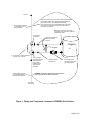
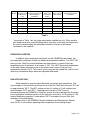
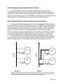
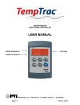
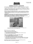
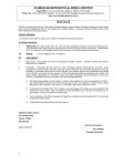
Form 34-400.7
Issue date:3-06
Installation Instructions - Supplemental
Commercial Pool Heater Application
®
for PRIMERA Models 400W, 750W, 1000W 1200W, 1600W and 2000W
Installation of the Commercial Pool Heater Package must be performed by a qualified service
installer or service agency. These instructions are to supplement the Installation and Maintenance
Manual provided with your PRIMERA water heater or boiler.
Before you begin, read and follow these instructions, as well as the information contained in the
PRIMERA® Installation and Maintenance Manual. To obtain an additional copy of the PRIMERA®
Installation and Maintenance Manual, or for any questions, call Riverside Hydronics, LLC
at 1-800-990-5918.
WARNING: If the information in the supplied instructions and manual(s) is not
followed exactly, a fire, explosion, exposure to hazardous materials or conditions or
other hazards may result, causing property damage, personal injury or loss of life.
If the water heaters are to be installed outdoors, refer to supplemental instruction sheet 34-400.4
for information on outdoor vent kit.
ADDITIONAL PARTS REQUIRED FOR POOL APPLICATIONS
Following is a list of parts required for application of PRIMERA water heaters into pools: Refer
to Figure 1 for their location.
1 – Thermostat, Honeywell #L4006A1678 (Riverside Hydronics part 57432)
1 – Well, Thermostat ¾ x 3” Long Honeywell #121371B (Riverside Hydronics 14960)
Honeywell thermowell requires a 3/4-inch fitting in the pool loop downstream of the
water heater.
TempTrac® Temperature Sensor Wells
Either single-probe well; part number 102560, or four-probe well; part number
102561. The single-probe well requires a 1/2 –inch fitting upstream of the water
heater in the pool loop. The four-probe well for multiple pool heater applications
requires a ¾-inch fitting upstream of the water heaters in the pool loop.
Page 1 of 5
To Pool
Install and permanently set to open at 130°F the Honeywell
thermostat #L4006A1678 100-240 deg w/adj differential,
part number 57432. On PRIMERA terminal strip,
remove jumper and connect thermostat leads to terminals
R1 and R2. Thermostat is for indoor use and must be
protected from weather.
3/4" NPT fitting required
for Honeywell 3/4” x 3”
thermostat well
Relief Valve - Plumb per local code.
In the absence of local code, plumb into
a suitable floor drain
From Heater
Connection
Flow and Temperature
Balancing Valves
A and B.
PRIMERA
A
®
2" bypass
L
H
B
L = a maximum of 4 pipe diameters
a minimum of 12 inches.
The “To Heater”
connection with the
main distribution
loop must be
upstream of the
“From Heater”
connection.
1/2" NPT fitting required
for Riverside Hydronics
Primera thermostat well
Union
Isolation valve for
maintenance.
Primera all bronze
circulator pump sized
per Primera I & M.
PRIMERA’s Probe #1 is moved from inlet of heater to
pool loop upstream of heater connections.
From Pool
Filter Pump
Figure 1: Piping and Component Location for PRIMERA Pool Heaters
Page 2 of 5
APPLICATION GUIDELINES
The water heater must be ordered for single-stage firing sequence only. Stage-fired
and modulating water heaters will not function properly in pool heating applications due
to the tremendous thermal mass represented by the water in the pool. Because this
thermal mass gains and loses energy slowly, there is no advantage to modulating the
energy input.
The TempTrac operating control must be adjusted for the low temperature set points
for pool applications:
ST1 parameter must be set to desired pool temperature; for example 80 degrees.
Hy1 parameter must be set to -2 (call-for-heat differential from ST1 parameter)
LS1 parameter must be set to 50 (minimum setpoint for ST1)
US1 parameter must be set to 108 (maximum setpoint for ST1)
Refer to TempTrac manual for instructions on resetting these parameters. (form 34-80)
Refer to Figure 1 for the following startup procedure. The low-temperature
bypass must be sized at 2 inches with a full-port ball valve. This is because more than
½ the flow to the heater inlet will come from the bypass in this low-temp application.
Temperature at the water heater inlet must be no less than 130 degrees and should be
adjusted to no higher than 140 degrees.
STARTUP PROCEDURE
1. Make sure PRIMERA temperature probe is in the inlet of water heater and not
2.
3.
4.
5.
6.
the pool filter loop for startup. This probe will be relocated to pool filter loop after
startup procedure is complete.
Close manual bypass valve (B). Fully open the isolation valve on the inlet piping
to the heater and the balancing valve on the outlet piping of the heater. Start the
heater and let run for 10 minutes.
Adjust the outlet manual balancing valve (A) until the proper temperature rise is
achieved through the heater. (see Table 1) This establishes proper flow rate.
Fully open the manual bypass valve (B).
Again throttle back the outlet valve (A) to reduce the flow of water exiting the
primary loop. This will increase the flow of heated water across the bypass and
into the water heater inlet. Valve A is correctly adjusted when water temperature
at the inlet of the heater is maintained between 130°F and 140°F after
approximately 10 minutes of heater operation. (when heating a cold pool to
operating temperature, valve A will have to be regularly readjusted as pool
temperature increases to desired level. Otherwise, water temperature at the
heater inlet will climb past the 140°F maximum when the desired pool
temperature is achieved.) Outlet temperature display should equal the inlet
temperature (130 to 140°) + the required temperature rise for the heater model.
Move Probe #1 from heater inlet to the pool filter loop upstream of the heater.
Page 3 of 5
PRIMERA Recommended Primera Inlet to Outlet
Model
Minimum Flow Temperature Rise After
in Main Pool
Manual Bypass
Loop
Adjustment
400
750
1000
1200
1600
2000
85 gpm
170 gpm
210 gpm
120 gpm
170 gpm
210 gpm
23
21
23
45
45
45
Maximum
Temp. from
Pool before
heating
108oF
o
108 F
o
108 F
o
108 F
o
108 F
o
108 F
Maximum
Minimum Copper Pipe Size
Temp. To Pool
Required For Primera
after heating
Connection *
130oF
2 inch
o
2 inch
o
2½ inch
o
2 inch
o
2 inch
o
2½ inch
130 F
130 F
130 F
130 F
130 F
Table 1
* pipe sizes in Table 1 are for single water heater installations only. When multiple
pool heaters are used, manifold piping that is shared by more than one heater must
be sized to accommodate the anticipated maximum flow rate of all heaters
connected to the manifold.
OPERATING SAFETIES
In addition to the temperature limits built into the PRIMERA water heater, the
pool application guidelines include two additional temperature safeties. The 108°F US1
setting on the TempTrac control disallows the water heater to operate if the loop
temperature prior to the heater is in excess of 108°. The 130°F thermostat downstream
of the water heater interrupts power to the heater control circuit if the pool loop
temperature reaches 130°F. This control is auto reset and will enable the control circuit
when loop temperature drops below an adjustable differential.
SPA APPLICATIONS
Water heaters for spas are piped identically as general pool applications. The
only exception to the instructions printed above is that the TempTrac setting for ST1 will
be approximately 105°F. That ST1 setting and an Hy1 setting of -2 will maintain spa
water between 103°F and 106°F. Temperatures in excess of 108°F are not
recommended and the PRIMERA’s TempTrac control should be adjusted as discussed
in the Application Guidelines section of this instruction manual for a US1 setting of 108,
thereby disallowing operation if water above 108°F is sensed in the pool filter loop
upstream of the water heater.
Please refer to the PRIMERA General Installation and Maintenance Manual
(form 34-50) for information regarding water temperature and scalding danger.
Page 4 of 5
POOL CHEMICALS AND WATER HEATER LOCATION
Due to the highly corrosive environment created by pool chemicals, the
PRIMERA water heaters should not be installed where these chemicals are stored. If
fumes may be carried into the water heater during combustion, remote combustion air
option must be specified. Failure of the PRIMERA heat exchanger or jacketing resulting
from exposure to pool chemicals is not covered under the product warranty.
MULTIPLE HEATER INSTALLATIONS AND LEAD-LAG CONTROLS
Lead-lag of multiple, single-stage pool heaters is accomplished simply by wiring
the lead-lag control to the R1 and R2 terminals on each PRIMERA heater (terminals are
located on the back of control box beneath the heater’s top pan). Heaters ship with a
jumper between R1 and R2 that must be removed if connecting to a lead-lag. The St1
control on the water heaters must be adjusted higher than the lead-lag setpoint to
enable the lead-lag to properly stage the heaters. The lead-lag must be wired in series
to each heater with a separate 130°F thermostat as shown in figure 1. The lead-lag
sensor must be adjacent to the PRIMERA temperature probe in the pool filter loop.
If the water heaters are designed to be operated separately and never together,
(100% redundancy only) a piping scheme similar to figure 2 is suitable. Otherwise, the
heaters should be piped in a reverse-return arrangement as indicated in figure 3.
Heater
1
Pool
Filter
Loop
Heater
Pool
Filter
Loop
Heater
Figure 2
Heater
Figure 3
Illustrations are simplified to emphasis general piping concepts. Figure 1 must be referenced for
details concerning probe locations and valve requirements. Shared piping (indicated by heavier
lines in figure 3) must be sized to accommodate the total flow of all boilers.
Page 5 of 5