1
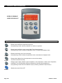
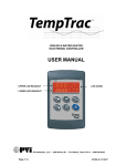
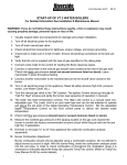
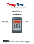
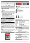
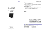
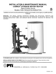
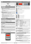
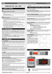
SERVICE & SETUP MANUAL
WATER HEATER
ELECTRONIC CONTROLLER
PVI Industries, LLC • 3209 Galvez Dr • Fort Worth, Texas 76111 • 800-784-8326
Page 1/ 24
PV500-41 10/2013
INDEX
1. TECHNICAL DATA _________________________________________________________________ 3
2. WIRING DIAGRAMS ________________________________________________________________ 3
3. DISPLAY AND INTERFACE __________________________________________________________ 4
3.1 KEYBOARD __________________________________________________________________ 4
3.2 LED ICON LEGEND ____________________________________________________________ 5
3.3 UPPER LED READOUT (RED) ___________________________________________________ 6
3.4 LOWER LED READOUT (YELLOW) _______________________________________________ 6
3.5 TO SET THE CURRENT TIME AND DAY (24 HOUR CLOCK) ___________________________ 6
3.6 TO SET THE ENERGY SAVINGS TIME ____________________________________________ 7
3.7 TO SET THE MODULATION OUTPUT MANUALLY ___________________________________ 7
3.8 HOW TO SEE THE WORKING HOURS OF RELAY OUTPUTS __________________________ 7
3.9 HOW TO RESET THE WORKING HOURS OF RELAY OUTPUTS _______________________ 7
4. PROGRAMMING___________________________________________________________________ 8
4.1 SET POINTS PROGRAMMING ___________________________________________________ 8
4.2 HOW TO ENTER AND CHANGE PARAMETERS IN THE “pr1” LIST (NOT PASSWORD
PROTECTED)_________________________________________________________________ 8
4.3 HOW TO ENTER PARAMETERS IN THE “Pr2” LIST (PASSWORD PROTECTED) __________ 8
4.4 HOW TO CHANGE THE PARAMETER VALUES IN “Pr2” ______________________________ 9
4.5 HOW TO LOCK THE KEYBOARD _________________________________________________ 9
5. PARAMETERS ___________________________________________________________________ 10
6. RELAY OUTPUTS ________________________________________________________________
6.1 OUTPUT SETUP AND SPECS __________________________________________________
6.2 OUTPUT 1 CALL FOR HEAT (1on=rEG) ___________________________________________
6.3 OUTPUT 2 2ND STAGE (oS2=Std 2on=rEG) _______________________________________
6.4 OUTPUT 2 AS ALARM RELAY (oS2=AL, 2ON=REG) _________________________________
6.5 OUTPUT 3 TEMPERATURE PROTECTION (3on=rEG) _______________________________
6.6 OUTPUT 3 ALTERNATE SET POINT _____________________________________________
7. MODULATION OUTPUT____________________________________________________________
14
14
14
15
15
16
17
18
8. MODULATION BUFFER ____________________________________________________________ 19
9. DYNAMIC RESET OF St1 __________________________________________________________ 19
10. WARM WEATHER SHUT DOWN _____________________________________________________ 19
11. HOT KEY PROGRAMMING _________________________________________________________ 20
12. ASSIGNING TEMPTRAC® ADDRESS FOR MODBUS RTU _______________________________ 21
13. ALARMS ________________________________________________________________________
13.1 DIGITAL INPUT ALARMS ______________________________________________________
13.2 AUDIBLE ALARM _____________________________________________________________
13.3 ALARM RECOVERY __________________________________________________________
Page 2/ 24
22
23
23
24
PV500-41 10/2013
1.
TECHNICAL DATA
Housing: Self-extinguishing ABS.
Case: Facia 100x64 mm; depth 76mm
Mounting: Panel mounting in a 56x72 mm panel cut-out with two screws. ∅ 3x2mm. Distance between the holes
40mm
Protection: IP20.
Frontal protection: IP65 with optional frontal gasket mod. RGW-V
Connections: Spade on connectors 6.3 mm for supply and relays and 4÷20mAScrew terminals block for probes, digital input
Power supply: 24Vac Class 2
Power absorption: 7VA max.
Display: Dual display
Relay outputs: 3 SPST relay contacts, 3A, 8A resistive load.
Other output: Audible alarm
4÷20mA modulation output
Inputs: 3 NTC probes
Digital inputs: 3 Dry Contact
Hot key facility for fast programming
Serial output: TTL standard
Communication protocol: Modbus - RTU
Data storing: On non-volatile memory (EEPROM).
Internal clock back-up: 24 hours
Kind of action: 1B.
Pollution grade: Normal
Software class: A.
Operating temperature: 32÷140°F (0÷60 °C)
Storage temperature: -13÷140°F (-25÷60 °C)
Relative humidity: 20÷85% (no condensing)
Measuring and regulation range: NTC probe: -58÷230°F (-40÷110°C)
Resolution: 1°F or 1 °C (selectable).
Accuracy (ambient temp. 77°F): ±1 °F ±1 digit
2.
WIRING DIAGRAMS
Page 3/ 24
PV500-41 10/2013
3.
DISPLAY AND INTERFACE
UPPER LED READOUT
LOWER LED READOUT
3.1
KEYBOARD
SET
UP
DOWN
CLOCK
EXT
-
Displays and modifies the temperature set points.
In programming mode it selects a parameter or confirms an operation.
-
Displays and modifies the energy saving (Night Time Setback) settings.
In programming mode it browses the parameter codes or increases the displayed value.
-
Displays the working hours of the load relays.
In programming mode it browses the parameter codes or decreases the displayed value.
-
Changes lower display from inlet temperature to current time and day.
To set the current time and day.
-
Changes upper display between outlet temperature, inlet temperature, outdoor reset temperature,
modulation % or the temperature difference between the inlet and outlet temperatures.
In programming mode it sets the modulation output (4-20mA). (Password is required (321).
-
Switches the control ON or OFF.
ON/OFF
Page 4/ 24
PV500-41 10/2013
KEY COMBINATIONS
3.2
+
To lock and unlock the keyboard.
+
To enter the programming mode.
+
To exit the programming mode.
LED ICON LEGEND
LED MODE
ON
ON
Flashing
ON
Function
Temperatures are displayed in degrees Fahrenheit.
Temperatures are displayed in degrees Celsius.
Output 1 time delay. Output 1 will not energize until AC1 time delay expires OR i3F=Edi and
the remote enable/disable is in standby (disabled).
Output 1 relay is on. Spade contacts 4 & 5 are closed.
Usually this is the primary CALL FOR HEAT.
Output 2 time delay. Output 2 will not energize until AC2 time delay expires. (On 2-stage
units only.)
Or oS2 is set to AL. (Output 2 is an alarm indicator and it is off.)
Output 2 relay is on or the AL2 alarm output is enabled. Spade contacts 6 & 7 are closed.
Flashing
Output 3 time delay. Output 3 will not energize until AC3 time delay expires.
ON
Output 3 relay is on. Spade contacts 8 & 9 are closed.
ON
Flashing
Modulation output signal is in manual control mode. Parameter PS4 should be set to nu for
automatic operation.
Or If dS1 or dS2 is set to display the modulation output value ANI.
Modulation is forced to value in i1S by digital input 1.
ON
Modulation output signal is automatically controlled by temperature probe 1.
Flashing
ON
Modulation output time delay is activated. Modulation output will remain at 4mA until the AC4
time delay expires.
Or Modulation will remain in low fire until probe 2 is below TH4 by the amount of HY4.
The outside temperature is displayed (top or bottom display). See dS1 & dS2.
FLASHING
Digital input 2 (alarm) is activated.
FLASHING
Digital input 3 (alarm) is activated.
FLASHING
and
are flashing other safety interlocks such as low water cut-off or high
When both
temperature limit may be in failure.
ON
Lower LED display is displaying time clock.
ON
Flashing
Ext
Pr1 ON
ES
PoF
FLASHING
While in the Pr2 menu, signals that current the parameter is accessible in the Pr1 menu.
ALARM signal (any alarm condition LA, HA, P1, P2, P3, AL2, AL3, Nn1, Nn2, Nn3).
FLASHING
Programmed working hours limit is exceeded. See oP1, oP2, oP3 & ou1, ou2, ou3.
ON
Working hours are displayed in the lower LED display.
ON
Pops Up
The Energy saving function is running. This is a LED dot under the ES label top left.
Displayed when trying to make a change, the Keypad is locked. See section 4.5.
Page 5/ 24
PV500-41 10/2013
3.3
UPPER LED READOUT (RED)
The default display of this readout is the temperature sensed at Probe 2. Probe 2 may display the tank stored
water temperature, outlet water temperature, flue gas temperature, ambient temperature, remote tank or
blended water temperature, etc., depending on the product and application. Refer to your specific water heaters
Installation and Maintenance Manual and the supplied wiring drawing. The upper LED readout can also be
switched to display Probe 1 or 3 (if used) or the modulation % or the temperature difference between Probe 1
and 2. If Probe 2 is not utilized, the display will show “nu”.
By pressing and releasing the
button once, the Upper LED will display the actual temperature sensed at
Probe 3. Probe 3 (if used) may display the flue gas temperature or outside ambient temperature, etc.,
depending on the product and application.
By pressing and releasing the
button again, the Upper LED will display the modulation %. If the product is
a non-modulating product, the displayed valve should not be considered.
By pressing and releasing the
button a third time, the Upper LED will display the difference between the
temperature sensed at Probe 2 (if used) and the temperature sensed at Probe 1.
To return to the default in the Upper LED readout, press the
temperature.
button to cycle back to the Probe 2
All of the display information described above is available for monitoring through the optional MODBUS RTU
interface.
3.4
LOWER LED READOUT (YELLOW)
The default display of this readout is the temperature sensed at Probe 1. Probe 1 will be inserted into the
appropriate area of the storage tank to provide effective temperature response for the heat source (this may
not be at the top of the tank). The lower LED readout can also be switched to display Probe 2 or 3 (if used) or
the modulation % or the Time of Day.
By pressing and releasing the
to return to default display.
3.5
button once, the Lower LED display will show the Time of Day. Press again
TO SET THE CURRENT TIME AND DAY (24 HOUR CLOCK)
1. Push and hold the
button for more than 3 seconds. The
LED ICON starts flashing and the “Hur” (hour)
parameter name is displayed in the Upper LED readout, its value is displayed in the Lower LED readout.
2. Pushing the
or
button alternates the LED readouts between the following:
• “Hur” (hour) in the Upper readout and its value in the lower readout.
• “Min” (minute) in the Upper readout, its value in the Lower readout.
• “dAY” (day) in the Upper readout, its value in the Lower readout.
3. To adjust a value, press the
pressing the
4. To exit push
button and the value in the Lower LED will start flashing. Change the value by
or
buttons. When correct, press
.
+
or wait 15 seconds without pressing any buttons.
NOTE: This device recognizes Sunday as the first day of the week and Saturday as the last.
Page 6/ 24
PV500-41 10/2013
3.6
TO SET THE ENERGY SAVINGS TIME
1. Push the
2. Use
button for more than 3 seconds and the first parameter of the energy saving will be displayed.
and
keys to browse them.
3. To change a value push
4. To exit, press
3.7
and
key followed by
or
.
or wait 30s without pressing any key.
TO SET THE MODULATION OUTPUT MANUALLY
1. Push and hold the
key for more than 3 seconds
LED switches ON and the PS4 parameter is displayed
in the upper display, while the PAS label is shown in the lower display. The passkey will be required to view and
manually change the modulation % value. Passkey is “321”.
2. Release the key, and insert the password as described in the par. 4.3. The value of PS4 will be displayed in the
lower display. (nu) stands for not used. Return to this condition for automatic operation.
3. To adjust modulation manually, push the
modified it.
4. To exit, press
and
key, the value starts flashing. Then use
or
keys to
or wait 30s without pressing any key.
NOTE: After a modification, it will be possible to enter the Modulation output setting without entering the
password for 10min. After this time you will be asked for the password again.
3.8
HOW TO SEE THE WORKING HOURS OF RELAY OUTPUTS
1. Push the
key for more than 3 seconds,
will show the working hours of the relay 1.
2. By pushing
3. To exit, press
3.9
or
LED switches ON, the display 2 will show ou1 and the display 1
keys, the working hours of other outputs are displayed.
and
or wait 30s without pressing any key.
HOW TO RESET THE WORKING HOURS OF RELAY OUTPUTS
1. To reset the working hours of a load enter Pr2 menu. See section 4.3.
2. Select the parameter: ou1 for the output 1 or ou2 for output 2 or ou3 for output 3.
3. Push the
Page 7/ 24
key, and the value will start flashing, use the
key to decrease the value.
PV500-41 10/2013
4.
4.1
PROGRAMMING
SET POINTS PROGRAMMING
1. Push the
key, the upper display will show the “St1”, while the lower display will show its value.
and
2. Use the
key to see the set point to be modified.
key to modify the displayed value. It starts flashing.
3. Push the
4. To change it push the
or
keys.
key to confirm the value and pass to the setting of next set point.
5. Push the
6. Repeat the operations for additional set points.
To exit: press
and
or wait 30s without pressing any key.
NOTE: Each point has a time out of 30 seconds. If no key is pressed within 30s the controller exits the set points
programming procedure.
NOTE: The set value is stored even when the procedure exits due to the 15 second expiration.
4.2
HOW TO CHANGE PARAMETERS IN THE “Pr1” LIST (NOT PASSWORD PROTECTED)
1. Enter the Programming mode by pressing the
and
key for 3s.
2. Select the required parameter. The name of the parameter is on the upper display and its value is on the lower
display.
key: the value of the parameter will start blinking.
3. Press the
4. Use
or
5. Press
To exit: Press
to change the value.
to store the new value and move to the following parameter.
and
and or wait 30s without pressing a key.
NOTE: The set value is stored even when the procedure exits due to the 15 second expiration.
4.3
HOW TO ENTER PARAMETERS IN THE “Pr2” LIST (PASSWORD PROTECTED)
1. Enter the “Pr1” level.
2. Press the DOWN key.
3. Select “Pr2” – “PAS” parameter and press the
4. The value ““0 - -” with a flashing zero is displayed.
key.
Use
or
keys to input the security code in the flashing digit; confirm the figure by pressing
5. The security code is “321”.
NOTE: each parameter in “Pr2” can be removed or put into “Pr1” (user level) by pressing
When a parameter is present also in “Pr1” the “Pr1” icon is on.
Page 8/ 24
.
+
PV500-41 10/2013
.
4.4
HOW TO CHANGE THE PARAMETER VALUES IN “Pr2”
1. Enter the Programming mode.
2. Select the required parameter with
keys.
key and the value will start blinking.
3. Press the
4. Use
or
or
keys to change its value.
to store the new value and move to the next parameter.
5. Press
To exit: Press
and
or wait 30s without pressing a key.
NOTE: the new programming is stored even if the procedure exits by time-out.
4.5
HOW TO LOCK THE KEYBOARD
1. Keep the
and
keys pressed together for more than 3 s.
2. The “PoF” message will be displayed and the keyboard is locked. At this point it is only possible to
view the set point. Any attempt to change a set point will display the “PoF” message.
3. Repeat step 1 to unlock the keyboard.
4. The “Pon” message will be displayed and the keyboard will be unlocked.
Page 9/ 24
PV500-41 10/2013
5.
PARAMETERS
All the parameters can be set in:
- Pr1: immediately accessible menu.
- Pr2: password protected menu.
Label: The displayed label when using the Keypad.
Range: Indicates the possible values and units that can be set.
Firm Version: Firmware of the TempTrac control can be viewed in the rEL parameter.
Label
St1
St2
St3
St5
HY1
LS1
US1
AC1
S2c
HY2
LS2
uS2
AC2
S3c
HY3
LS3
uS3
AC3
o3P
SSE
HY5
Ac5
AcA
Firm
Version
Description
0.3 & 0.5
Range
X÷Y From X to Y
Rev 0.3
Level
Rev 0.5
Level
Set point1
LS1÷US1
Pr1
Pr1
0.3 & 0.5
Set point2
LS2÷US2
Pr1
Pr1
0.3 & 0.5
Set point3
LS3÷US3
Pr1
Pr1
0.3 & 0.5
Set point5 Set point 3 alternate
-20÷70°F
Pr1
Pr1
0.3 & 0.5
Differential for St1
-22÷22°F
Pr2
Pr2
0.3 & 0.5
Minimum set point1
-40°F÷SET
Pr2
Pr2
0.3 & 0.5
Maximum set point1
SET ÷ 230°F
Pr2
Pr2
0.3 & 0.5
Anti-short cycle delay for output 1
0÷30 min.
Pr2
Pr2
0.3 & 0.5
Configuration of St2: dependent on St1 or independent
diP; ind
Pr3
Pr2
0.3 & 0.5
Differential for St2
-22÷22°F
Pr2
Pr2
0.3 & 0.5
Minimum set point2
-40°F÷St2
Pr2
Pr2
0.3 & 0.5
Maximum set point2
St2 ÷ 230°F
Pr2
Pr2
0.3 & 0.5
Anti-short cycle delay for output 2
0÷30 min.
Pr2
Pr2
0.3 & 0.5
Configuration of St3: dependent on St1 or independent
diP; ind
Pr2
Pr2
0.3 & 0.5
Differential for set point 3 St3
-22÷22°F
Pr2
Pr2
0.3 & 0.5
Minimum set point 3 St3
-40°F÷St3
Pr2
Pr2
0.3 & 0.5
Maximum set point 3 St3
St3 ÷ 230°F
Pr2
Pr2
0.3 & 0.5
Anti-short cycle delay for output 3
0÷30 min.
Pr2
Pr2
0.3 & 0.5
Probe selection for output 3
Pb1 / Pb2
Pr2
Pr2
0.3 & 0.5
Set point shift for output 3 enable disable
No; Yes
Pr2
Pr2
0.3 & 0.5
Differential for set point 5
-22÷22°F
Pr2
Pr2
0.3 & 0.5
Anti-short cycle delay for output 3 alternate set point
0÷30 min.
Pr2
Pr2
0.3 & 0.5
Time delay between the St3 to St5 set point shift
0÷15 min.
Pr2
Pr2
Hex
Modbus
Address
Base 0
Modbus
Command
Address
40000+
0x300
0x301
0x302
0x303
0x304
0x305
0x306
0x307
0x308
0x309
0x30A
0x30B
0x30C
0x30D
0x30E
0x30F
0x310
0x311
0x312
0x313
0x314
0x315
0x316
769
770
771
772
773
774
775
776
777
778
779
780
781
782
783
784
785
786
787
788
789
790
791
0x317
0x318
0x319
792
793
794
0x31A
0x31B
0x31C
0x31D
0x31E
795
796
797
798
799
0x31F
0x320
0x321
0x322
800
801
802
803
ANALOGUE OUTPUT 4÷20mA (output 4)
S4c
St4
SR
0.3 & 0.5
Configuration of St4: dependent on St1 or independent
diP; ind
Pr3
Pr2
0.3 & 0.5
Analogue output set point
-100÷100°F
Pr2
Pr2
0.3 & 0.5
-100÷100°F
Pr2
Pr2
Th4
0.3 & 0.5
HY4
Ac4
PS4
PP4
0.3 & 0.5
Analogue output band width
Outlet temperature threshold for forcing to 4ma the
analog output
Differential for restart working of analog output
0.3 & 0.5
-40°F ÷ 230°F
Pr2
Pr2
-45 ÷ -1 °F
Pr2
Pr2
Anti-short cycle delay for output 4
0÷30 min.
Pr2
Pr2
0.3 & 0.5
Analog output percentage (nu=101)
0÷100, nu
Pr2
Pr2
0.3 & 0.5
Analog output percentage with fault probe 1 (nu=101)
0÷100, nu
Pr3
Pr2
DYNAMIC RESET
tt
rr2
rr1
tt2
0.3 & 0.5
Outdoor temperature threshold for dynamic reset of St1
-40÷230°F
Pr2
Pr2
0.3 & 0.5
Outdoor temperature band width
-100÷100°F
Pr2
Pr2
0.3 & 0.5
Maximum shift of St1
-100÷100°F
Pr2
Pr2
0.3 & 0.5
Outdoor temperature threshold to open all the loads
-40÷230°F
Pr2
Pr2
Page 10/ 24
PV500-41 10/2013
Label
Ht2
Firm
Version
Description
Range
X÷Y From X to Y
-45 ÷ -1 °F
Rev 0.3
Level
Rev 0.5
Level
Hex
Modbus
Address
Base 0
Pr2
Pr2
0x323
804
0x324
0x325
0x326
0x327
0x328
805
806
807
808
809
0x329
0x32A
0x32B
810
811
812
Pr2
0x32B
0x32C
812
813
Pr2
0x32C
813
814
815
816
817
818
Modbus
Command
Address
40000+
0.3 & 0.5
Differential for restart working of controller
0.3 & 0.5
DIGITAL INPUTS
0.3 & 0.5
Digital input 1 polarity
CL÷OP
Pr3
Pr2
0.3 & 0.5
Digital input 2 polarity
CL÷OP
Pr2
Pr2
0.3 & 0.5
Digital input 2 alarm delay
0÷255 min.
Pr3
Pr2
0.3 & 0.5
Digital input 3 polarity
CL÷OP
Pr2
Pr2
0.3 & 0.5
Digital input 3 alarm delay
0÷255 min.
Pr3
Pr2
0.3 & 0.5
DISPLAY
cF
rES
dS2
0.3 & 0.5
Temperature measurement unit
°C ÷ °F
Pr3
Pr2
0.3 & 0.5
Resolution (integer/decimal point) only for °C
in ÷ de
Pr3
Pr2
0.3
Default showing for display #2 Top (red)
Pb2, Pb3
Pr2
dS2
0.5
Default showing for display #2 Top (red) Pb3 will display
yellow EXT, Ani will display yellow Valve/M
dS1
0.3
Default showing for display #1 Bottom (Yellow)
dS1
0.5
Default showing for display #1 Bottom (Yellow) Pb3 will
display yellow EXT, Ani will display yellow Valve/M
Alc
0.3 & 0.5
Temperature alarms configuration: dependent on St1 or
independent
Pr3
Pr2
ALL
Alu
AFH
ALd
0.3 & 0.5
minimum temperature alarm, referred to TP1
-40÷230°F
Pr2
Pr2
0.3 & 0.5
MAXIMUM temperature alarm, referred to TP1
-40÷230°F
Pr3
Pr2
0.3 & 0.5
Differential for temperature alarm recovery
1÷45°F
Pr2
Pr2
0.3 & 0.5
Temperature alarm delay
0÷255 min.
Pr2
Pr2
0x32D
0x32E
0x32F
0x330
0x331
0.3 & 0.5
Delay of temperature alarm at start up 1 = 10 min disp
0.1
Pr2
Pr2
0x332
819
0x333
0x334
0x335
0x336
0x337
820
821
822
823
824
0x338
0x339
0x33A
825
826
827
0x33B
0x33C
0x33D
0x33E
0x33F
0x340
0x341
0x342
0x343
0x344
0x345
0x346
0x347
828
829
830
831
832
833
834
835
836
837
838
839
840
i1P
i2P
i2d
i3P
i3d
Pb1,Pb2,Pb3,AnI
Pb1; tiM
Pr2
Pb1,Pb2,Pb3,AnI,
TiM
ALARMS
dAo
rE÷Ab
0 ÷ 23h 50 min.
ANALOGUE INPUTS
oF1
P2P
oF2
P3P
oF3
0.3 & 0.5
First probe calibration
-21÷21°F
Pr3
Pr2
0.3 & 0.5
Second probe presence
No; Yes
Pr2
Pr2
0.3 & 0.5
Second probe calibration
-21÷21°F
Pr3
Pr2
0.3 & 0.5
Third probe presence
No; Yes
Pr2
Pr2
0.3 & 0.5
Third probe calibration
-21÷21°F
Pr3
Pr2
TIME AND DATE
Hur
Min
dAY
0.3 & 0.5
Current hour
0 ÷ 23
Pr2
Pr2
0.3 & 0.5
Current minute
0 ÷ 59
Pr2
Pr2
0.3 & 0.5
Current day
Sun ÷ SAt
Pr2
Pr2
ENERGY SAVING TIMES
E1
S1
Sb1
E2
S2
Sb2
E3
S3
Sb3
E4
S4
Sb4
E5
0.3 & 0.5
Energy saving start on Sunday
0 ÷ 23h 50 min. - nu
Pr2
Pr2
0.3 & 0.5
Energy saving stop on Sunday
0 ÷ 23h 50 min. - nu
Pr2
Pr2
0.3 & 0.5
Set back temperature on Sunday
-40÷40°F
Pr2
Pr2
0.3 & 0.5
Energy saving start on Monday
0 ÷ 23h 50 min. - nu
Pr2
Pr2
0.3 & 0.5
Energy saving stop on Monday
0 ÷ 23h 50 min. - nu
Pr2
Pr2
0.3 & 0.5
Set back temperature on Monday
-40÷40°F
Pr2
Pr2
0.3 & 0.5
Energy saving start on Tuesday
0 ÷ 23h 50 min. - nu
Pr2
Pr2
0.3 & 0.5
Energy saving stop on Tuesday
0 ÷ 23h 50 min. - nu
Pr2
Pr2
0.3 & 0.5
Set back temperature on Tuesday
-40÷40°F
Pr2
Pr2
0.3 & 0.5
Energy saving start on Wednesday
0 ÷ 23h 50 min. - nu
Pr2
Pr2
0.3 & 0.5
Energy saving stop on Wednesday
0 ÷ 23h 50 min. - nu
Pr2
Pr2
0.3 & 0.5
Set back temperature on Wednesday
-40÷40°F
Pr2
Pr2
0.3 & 0.5
Energy saving start on Thursday
0 ÷ 23h 50 min. - nu
Pr2
Pr2
Page 11/ 24
PV500-41 10/2013
Label
S5
Sb5
E6
S6
Sb6
E7
S7
Sb7
Firm
Version
Description
0.3 & 0.5
Energy saving stop on Thursday
0.3 & 0.5
Set back temperature on Thursday
0.3 & 0.5
Range
X÷Y From X to Y
0 ÷ 23h 50 min. - nu
Rev 0.3
Level
Rev 0.5
Level
Pr2
Pr2
-40÷40°F
Pr2
Pr2
Energy saving start on Friday
0 ÷ 23h 50 min. - nu
Pr2
Pr2
0.3 & 0.5
Energy saving stop on Friday
0 ÷ 23h 50 min. - nu
Pr2
Pr2
0.3 & 0.5
Set back temperature on Friday
-40÷40°F
Pr2
Pr2
0.3 & 0.5
Energy saving start on Saturday
0 ÷ 23h 50 min. - nu
Pr2
Pr2
0.3 & 0.5
Energy saving stop on Saturday
0 ÷ 23h 50 min. - nu
Pr2
Pr2
0.3 & 0.5
Set back temperature on Saturday
-40÷40°F
Pr2
Pr2
Hex
Modbus
Address
Base 0
Modbus
Command
Address
40000+
0x348
0x349
0x34A
0x34B
0x34C
0x34D
0x34E
0x34F
841
842
843
844
845
846
847
848
849
850
851
WORKING HOURS
ou1
ou2
ou3
0.3 & 0.5
working hours actual of relay 1
0÷9999h
Pr1
Pr2
0.3 & 0.5
working hours actual of relay 2
0÷9999h
Pr1
Pr2
0.3 & 0.5
working hours actual of relay 3
0÷9999h
Pr2
Pr2
0x350
0x351
0x352
Pr2
Pr2
0x353
852
Pr2
Pr2
0x354
853
Pr2
Pr2
0x355
854
Pr2
Pr2
0x356
855
Pr2
Pr2
0x357
856
Pr2
Pr2
0x358
857
0x359
0x35A
0x35B
0x35C
858
859
860
861
Pr2
0x35D
0x35E
862
863
Pr2
0x35F
864
Pr2
0x360
865
Pr2
oP1
0.3 & 0.5
working hours limit of relay 1
oP2
0.3 & 0.5
working hours limit of relay 2
oP3
0.3 & 0.5
working hours limit of relay 3
0÷9999h; with 0 the
function is disabled
0÷9999h; with 0 the
function is disabled
0÷9999h; with 0 the
function is disabled
OUTPUTS SETTING
1on
0.3 & 0.5
The output 1 is always on or depending on temperature
2on
0.3 & 0.5
The output 2 is always on or depending on temperature
3on
0.3 & 0.5
The output 3 is always on or depending on temperature
rEG=1,1;YES=0,1;
no=0,0
rEG=1,1;YES=0,1;
no=0,0
rEG=1,1;YES=0,1;
no=0,0
OTHER
Adr
Ptb
rEL
i1S
0.3 & 0.5
Serial address
0÷247
Pr2
Pr2
0.3 & 0.5
Parameter map code always = 1
readable only
Pr2
Pr2
0.3 & 0.5
Software release 5 = 0.5, 3 = 0.3
readable only
Pr2
0.5
Analog output when Digital Input 1 is activated
4-20mA
i1t
0.5
Analog output at i1S extra time if Digital Input 1 is not
activated
0÷30 sec.
i1d
0.5
Digital Input 1 Alarm Delay
i1F
0.5
i2F
0.5
i3F
0.5
oS2
0.5
0.3 & 0.5
0.3
0.3 & 0.5
0.3
0.3 & 0.5
Page 12/ 24
If Yes, Digital Input 1 will function as Alarm. Operating
only when trying to call for output 1 and Input 1 is
active, subject to i1d timer
Digital Input 2 will function only when Output 1 is
energized
Digital Input 3 will function only when Output 1 is
energized, When Edi is selected, Output 1 will open
when digital input 3 is activated
Output 2 function: either temp relay or alarm relay
Probe 1 temperature
Probe 1 Information/Status Normal=512 or 0x0200,
Fault=515 or 0x0203. Fault will, drop call for heat, buz,
Flash Yellow P1, light yellow valve/M
Probe 2 temperature
Probe 2 Information/Status Normal=512 or 0x0200,
Fault=515 or 0x0203. Fault will buz, Flash Red P2
Probe 3 temperature
0÷255 min.
Pr2
Pr2
Pr2
No; Yes
No; Yes
No; Yes; Edi
Std; AL
Pr2
0x361
0x362
866
867
Degrees F/C
Pr2
0x100
257
Pr2
0x101
0x102
258
259
0x103
0x104
260
261
bit (0,1 on) probe
failure
Degrees F/C
Pr2
bit (0,1 on) probe
failure
Pr2
Degrees F/C
Pr2
PV500-41 10/2013
0.3
Probe 3 Information/Status Normal=512 or 0x0200,
Fault=515 or 0x0203. Fault will buz, Flash Red P3
0.5
0.3 & 0.5
bit (0,1 on) probe
failure
Pr2
Modulation rate output (4 to 20mA)
0÷100%
Pr2
Status of Relay 1,2&3
bit 0,1,2
Pr2
0x105
0x106
0x801
262
263
2050
3329
3329
3329
0.3
Input 3 Alarm, buz, ALMMB, Flashes HP= 4096 or
0x0800
bit # 12 or 13th bit
0.3
Input 2 Alarm, buz, Flashes LP= 4096 or 0x0800
bit # 12 or 13th bit
Pr2
0.3
Input 2 & 3, buz, Flashed HP & LP= 4096 or 0X0800
bit # 12 or 13th bit
Pr2
0xD00
0xD00
0xD00
0.5
Low Temperature Alarm, beep, Flash Yellow LA= 1 or
0x0001
High Temperature Alarm, beep, Flash yellow HA= 2 or
0x0002
Probe 1 error, open or shorted, Drops call for heat, yel
valve/M on, Flash Yellow P1=4 or 0x0004
Probe 2 error, open or shorted, Flashing red P2=256 or
0x0100
Probe 3 error, open or shorted, Flashing red P3=512 or
0x0200
ALARM 1 (stops heating) Input 1, beep, Flash AL1 = 1024
or 0x0400. Will recover is Input 1 goes away, or need for
call for heat goes away.
ALARM 2 (Lockout, stops heating) Input 2, Flash AL2 &
Lguage & valve= 2048 or 0x1000
ALARM 3 (Lockout, stops heating) Input
3/ALMMB/ALOAF, beep, Flash AL3 & Hguage & valve
(This is ALARM ON ANY FAILURE)= 4096 or 0x0800
Maintenance Relay1, beep, Flash Nn1 & wrench=8192
or 0x2000 You must reset hours ou1 or set oP1=0
Maintenance Relay2, beep, Flash Nn2 & wrench=16384
or 0x4000 You must reset hours ou2 or set oP2=0
Maintenance Relay3, beep, Flash Nn3 & wrench=32768
or 0x8000 You must reset hours ou3 or set oP3=0
Pr2
0xD00
3329
Pr2
0xD00
3329
Pr2
0xD00
3329
Pr2
0xD00
3329
Pr2
0xD00
3329
Pr2
0xD00
3329
Pr2
0xD00
3329
Pr2
0xD00
3329
Pr2
0xD00
3329
Pr2
0xD00
3329
Pr2
0xD00
3329
Pr2
0x500
1281
Pr2
0x500
1281
Pr2
0x500
1281
0.5
0.5
0.5
0.5
0.5
0.5
0.5
0.5
0.5
0.5
0.3
On/Off On=257 or 0x0101, Off=1 or 0x0001 Can be used
to reset ALMMB alarm by cycling OFF, wait 30 sec , ON
0.3
Keyboard Lock Lock=2056 or 0x0808, Unlock=8 or
0x0008. If locked PoF is displayed when keypad edit is
attempted
0.3
Reset audible alarm when condition is corrected, 4112
or 0x1010 does not reset alarm, just stops the beeping
bit # 0 or 1st bit
bit # 1 or 2nd bit
bit # 2 or 3rd bit
bit # 8 or 9th bit
bit # 9 or 10th bit
Pr2
bit # 10 or 11th bit
bit # 11 or 12th bit
bit # 12 or 13th bit
bit # 13 or 14th bit
bit # 14 or 15th bit
bit # 15 or 16th bit
Low byte is mask, Hi
byte is command. Bit
# 0 & #8
Low byte is mask, Hi
byte is command. Bit
# 3 & #11
Low byte is mask, Hi
byte is command. Bit
# 3 & #12
Energy Savings Registers are enumerated 0 to 145
w/145=n/u
Page 13/ 24
PV500-41 10/2013
6.
RELAY OUTPUTS
6.1
OUTPUT SETUP AND SPECS
1. 3 relay outputs. SPST relay contacts going to spade terminals #4-9.
2. The outputs are rated at 3A, or 8A resistive load.
3. Each output (1-3) can be controlled via Modbus RTU Communication by setting on or oFF to the 1on, 2on, 3on
parameters.
4. Each output can be configured to operate as a control output, typically for temperature control. This is done when
1on, 2on, 3on respectively are set to rEG. This is the default setting.
a. 1on=rEG Output 1 is configured for Temperature Control (Same for 2on, 3on).
b. 1on=oFF Output 1 is off.
c. 1on=on Output 1 is on any time the TempTrac is enabled (Alarms will not disable). On power loss, this contact
will be open, and when the TempTrac displays OFF, this will contact will be open. This is no longer a control
output, and is not subject to alarms.
5. Output 1, Spade terminals 4 & 5.
6. Output 2, Spade terminals 6 & 7.
7. Output 3, Spade terminals 8 & 9.
6.2
OUTPUT 1 CALL FOR HEAT (1on=rEG)
Kind of action: Heating
Reference probe: TP1
Terminals: SPADE 4 & 5
Related Parameters: St1, Hy1, LS1, US1, AC1, i3F, 1on
Probe1
Set1
Set1+ Hy1
time
Out1
time
NOTES
1. When probe 1 TP1 falls below St1, a call for heat output will occur.
2. Hy1 is the differential to prevent short cycling.
3. When Hy1 is negative, this will prevent the call for heat from starting until TP1 falls below St1 + Hy1. The call for
heat will continue until TP1 reaches or goes above St1. See chart above.
4. If Hy1 is positive, then the call for heat will start when TP1 falls below St1, and will stay active until TP1 rises
above St1 + Hy1. Not shown on chart.
Page 14/ 24
PV500-41 10/2013
6.3
OUTPUT 2 2ND STAGE (oS2=Std 2on=rEG)
Kind of action: Heating
Reference probe: TP1
Terminals: SPADE 6 & 7
Related Parameters: S2c, St2, Hy2, LS2, US2, AC2, oS2, 2on
Probe1
Set2
Set2+ Hy2
time
Out2
time
NOTES
1. Output 2 will function as an output temperature control when oS2=Std, otherwise output 2 is an alarm output
contact.
2. S2c determines if St2 is relative to St1 or independent. (S2c=dep or ind.)
3. Hy2 functionality same as Hy1. See OUTPUT 1 CALL FOR HEAT.
6.4
OUTPUT 2 AS ALARM RELAY (oS2=AL, 2ON=REG)
1. Output 2 will function as an alarm contact when oS2=AL.
2. When an alarm condition occurs, Output 2 will be energized (relay closes) as an indication of an alarm condition.
3. Terminals: SPADE 6 & 7.
Page 15/ 24
PV500-41 10/2013
6.5
OUTPUT 3 TEMPERATURE PROTECTION (3on=rEG)
Kind of action: Heating
Reference probe: TP1 or TP2
Terminals: SPADE 8 & 9
Related Parameters: S3c, St3, Hy3, LS3, uS3, AC3, 3on, o3P
Probe2
Set3
Set3+ Hy3
time
Out3
time
NOTES
1. Output 3 can be used to enable pumps when temperature falls below a St3.
2. o3P will select the probe for Output 3. Pb1 or Pb2.
Page 16/ 24
PV500-41 10/2013
6.6
OUTPUT 3 ALTERNATE SET POINT
Kind of action: Heating
Reference probe: TP1 or TP2
Related Parameters: St3, Hy3, LS3, US3, AC3, St5, Hy5, 3on, o3P, SSE, AC5, ACA
NOTES
1. When SSE is enabled and Output 1 is in a de-energized state (off) Output 3 will function according to St3. When
Output 1 is in an energized state Output 3 will function according to St5.
2. ACA delays the change from St3 to St5.
3. o3P selects temperature probe to be referenced by Output 3.
4. Hy1, Hy3 and Hy5 are active but not shown in this illustration.
Alternate Set Point Control
Set-Point
Shift
Set 3
Set 1
Set 5
On
Out 3
Off
Set 5
On
Out 1
Set 3
Set 5
Set 3
Off
ACA Time
Delay
Page 17/ 24
Time
PV500-41 10/2013
7.
MODULATION OUTPUT
Kind of action: if Sr< 0 Heating; if Sr>0 Cooling. See diagrams.
Current
(mA)
20
Current
(mA)
20
Sr < 0
4
Sr > 0
4
Set4 + Sr
Set4
Temper.
Set4
Set4 + Sr
Temper.
Reference probe: TP1
Related Parameters: S4c, St4, Sr, PS4, PP4, Ac4, i1S, i1t, i1F, i1d
NOTES
1. The kind of action of the modulation output depends on the sign of the Sr parameter.
2. If the parameter PS4 is different from nu, the percentage of the modulation output depends on the value set in
PS4, independently from the value of the probe. (0-100% represents 4mA to 20mA.)
3. If i1F=No and digital input 1 is ACTIVE, the analog modulation output is forced to the mA set in i1S parameter
independently from the value of the probe and the value of the PS4 parameters. After digital input 1 is no longer
ACTIVE, the analog output will stay at the actual mA value set in i1S for the time period set by at the i1t
parameter.
4. If the probe TP1 is broken, PS4=nu and the digital input 1 is off, the value of the modulation output depends on
the PP4 parameter.
5. The value of the PS4 parameter can be set directly by the keyboard. See par. 3.6.
6. Anti-short cycle delay for the analog output: when the analog output reaches the 4mA, it is held at 4mA for this
time. During this time the
icon is flashing. When this delay has expired, normal functioning of modulation
output restarts. This delay will be reinitiated again after output 1 switches off.
7. Ranges: i1S (4-20 range) is actual mA, i1t (0-30 range) is seconds. PS4 & PP4 (0-100 & nu range) is percentage
of output 0%=4mA 100%=20mA nu=AUTO.
Page 18/ 24
PV500-41 10/2013
8.
MODULATION BUFFER
Probe 2
Th4
Th4+HY4
20ma
Out 4
Time
4ma
Kind of action: Heating
Reference probe: TP2
Related Parameters: Th4, HY4
NOTES
1. This function references probe TP2 and will trigger output 4 to reduce the signal to 4mA when the temperature of
Th4 is reached by TP2 and hold it until TP2 drops below TH4+HY4. Output 4 then returns to normal operation
referencing TP1.
9.
DYNAMIC RESET OF St1
Kind of action: Inverse
Reference probe: TP3
Related Parameters: tt, rr2, St1, rr1
If the outdoor temperature is lower than tt the dynamic reset of the St1 action starts as described in the following
diagrams.
Temper.
Set1+rr1
Set1
tt + rr2
NOTES
1. With rr1=0 the dynamic reset of the set point 1 is disabled.
tt
Probe 3
Outdoor
Temper.
Temperature
2. If the TP3 is not present (P3P=no) or broken, the dynamic reset of the set point 1 is disabled.
10. WARM WEATHER SHUT DOWN
The tt2 parameter, referring to the outdoor probe TP3, establishes the upper threshold which all the relay outputs are
open. Normal regulation restarts when TP3< tt2+Ht2.
To disable this function set tt2 to high a value. If the third probe is not present P3P=no, this function is disabled.
Page 19/ 24
PV500-41 10/2013
11. HOT KEY PROGRAMMING
To upload program from control to HOT KEY:
Insert HOT KEY into the TTL/HOT KEY connection on the back of the control. Press
+
and
keys together momentarily then press the
key. The uPL
message will appear while uploading is occurring and the End message will appear
when finished. Push any key to return to normal operation.
To download program from HOT KEY to control:
ON/OFF
Press the ON/OFF key to turn off the control. Insert the HOT KEY into the TTL connection on the back
of the control. Press the ON/OFF key again and downloading will begin. The DoL message will appear
while downloading is occurring and the End message will appear when finished. Push any key to return
to normal operation.
If err message is displayed during upload or download the programming failed. The cause of a failed program may
be user error, faulty control or Hot Key.
Page 20/ 24
PV500-41 10/2013
12. ASSIGNING TEMPTRAC® ADDRESS FOR MODBUS RTU
The first step to interfacing a BAS (Building Automation Control) with a water heater or group of water heaters will be the
assignment of the address number for each heater.
1. Enter the Programming mode by pressing the Set
(lead with the SET key.)
and DOWN
key for 3s.
2. Press the DOWN key.
3. Select “Pr2” – “PAS” parameter and press the “SET” key.
4. The value “0 - -” with a flashing zero is displayed.
5. Use UP or DOWN keys to input the Passkey in the flashing digit; confirm the figure
by pressing “SET”. The Passkey is “321”.
Adr
1
6. Once you have entered the Pr2 menu press the DOWN key until the parameter Adr
appears on the screen as shown to the right:
7. Now press the SET key once and the number will begin to blink. Use the arrow key
to set the address. Each TempTrac on a RS-485 network must have a different
address, to enable proper communication.
NOTE: The default for each TempTrac is Address #1. You can assign them to any
number in the range of 1-247, this is the limitations of the MODBUS-RTU standard.
Page 21/ 24
PV500-41 10/2013
13. ALARMS
Alarm messages are displayed in the lower display of the TempTrac and are alternated with the default message.
These alarm messages are displayed together with the icon devoted to signalling the alarm conditions.
Message Cause
“P1”
“P2”
“P3”
“HA”
“LA”
“AL1”
“AL2”
“AL3”
“Nn1”
“Nn2”
“Nn3”
“rtc”
“rtF”
Page 22/ 24
Outputs and information
Audible alarm sounds. Output 1 and 2, if depending on the probe, open;
TP1 probe failure. Open or
modulation output, if depending on the probe, according to the PP4
shorted
parameter. Inspect probe 1; Screw terminals 14 & 17.
TP2 probe failure. Open or
Audible alarm sounds. Output 3 open. Inspect probe 2; Screw terminals
shorted
15 & 17.
Audible alarm sounds. Dynamic reset of St1 disabled. Warm weather shut
TP3 probe failure. Open or
down disabled. Flue Gas Temperature Protection disabled.
shorted
Inspect probe 3; Screw terminals 16 & 17.
High-temperature limit set point Audible alarm sounds, operation continues. see ALu.
exceeded
Low-temperature alarm
Audible alarm sounds, operation continues. see ALL.
Opens Output 1. Subject to “need” for Output 1, and i1d. Automatic
Digital Input 1 ACTIVE and
recover if the need for Output 1 is gone. With the loss of Input 1 signal,
configured as Alarm
alarm is still active until a button is pressed. See i1F, i1P, i1d.
Digital Input 2 is ACTIVE for
Audible alarm sounds. There is a time delay before this alarm is ACTIVE.
one or more of the conditions
Opens all temperature controlled outputs. Lockout condition. See oS2,
listed in section Audible Alarm i2d, i2P, i2F.
Digital Input 3 is ACTIVE for
Audible alarm sounds. There is a time delay before this alarm is ACTIVE.
one or more of the conditions
Opens all temperature controlled outputs. Lockout condition. This is also
listed in section Audible Alarm the alarm for the ALMMB or ALOAF option code sometimes referred to as
Alarm On Failure. See i3d, i3F, i3P.
Maintenance alert for call-forAudible alarm sounds, operation continues. Maintenance Required; hours
heat
on ou1 exceed setting in oP1. Clear ou1 (
Flashing).
Maintenance alert for second
Audible alarm sounds, operation continues. Maintenance Required; hours
stage
on ou2 exceed setting in oP2. Clear ou1 (
Flashing).
Maintenance alert for freeze
Audible alarm sounds, operation continues. Maintenance Required; hours
protection
Flashing).
on ou3 exceed setting in oP3. Clear ou1 (
The real time clock has lost its Energy saving functions disabled. (Can occur after powered down for
setting
extended time.)
Real time clock failure
Energy saving functions disabled. (TempTrac® requires replacement.)
PV500-41 10/2013
13.1 DIGITAL INPUT ALARMS
Digital Inputs
Polarity of the inputs is determined by the i1p, i2p, i3p parameters. If they are set to “CL” (closed) then a signal is
present when the input terminal has a connection to the common (COM) terminal #21. When the parameter is set to
“OP” (open) then a signal is present when the input terminal does not have a connection to the common (COM)
terminal.
Digital Input 1 (Screw terminal #18, COM #21)
1. When a signal is continuously present for number of minutes in parameter i1d, the input is then ACTIVE.
2. When i1F=Yes, Digital input 1 is assigned to the alarm function and considered only when there is a need for
Output 1.
3. When digital input 1 is ACTIVE, “AL1” will flash, and Output 1 will be disabled. Output 2 and 3 will continue to
function.
4. This alarm will reset automatically if the need for Output 1 is removed (Probe 1 temperature rises above setpoint).
5. If i1F=No Digital Input 1 is not used as an alarm, but used as way method of forcing a specified modulation rate.
See details about the i1S modulation function; refer to the MODULATION Output section of the manual.
Digital Input 2 (Screw terminal #19, COM #21)
1. When a signal is continuously present for number of minutes in parameter i2d, the input is then ACTIVE.
2. When i2F=Yes, Digital input 2 ACTIVE is considered only if Output 1 is energized.
3. When digital input 2 is ACTIVE, “AL2” will flash.
Digital Input 3 (Screw terminal #20, COM #21)
1. When a signal is continuously present for number of minutes in parameter i3d, the input is then ACTIVE.
2. When i3F=No, Digital input 3 ACTIVE functions as an alarm independent of output 1. “AL3” will flash for this
condition.
3. When i3F=Yes, Digital input 3 ACTIVE functions as an alarm and is considered only if Output 1 is energized.
“AL3” will flash for this condition.
4. When i3F=Edi, Digital input 3 ACTIVE de-energizes Output 1, and alarm conditions will not be registered in
memory or indicated in any way until Digital input 3 deactivates. Note: no existing alarm indication will be shown
until Digital input 3 state changes (neither an alarm icon, the AL# indication on the display nor the audible alarm
activation). (This feature is still subject to the i3d timer.)
The Instrument will revert to normal operation when these digital inputs are disabled + any button is pressed.
13.2 AUDIBLE ALARM
The TempTrac audible alarm is activated each time a connected alarm condition occurs. The following are
representative alarm conditions that may be connected to and activate the TempTrac audible alarm (some alarms
may be connected to and operate separately from the TempTrac on some products).
- High/low water temperature alarm
-
Probe failures
-
External thermostat limit failure
-
Flame Failure
-
High and low gas pressure
-
Low water
The audible alarm is silenced by pressing any key (alarm condition still present).
Page 23/ 24
PV500-41 10/2013
13.3 ALARM RECOVERY
1. Probe alarms: “P1”, “P2”, and “P3”; automatically stop a few seconds after the probe returns to normal operation.
Check connections before replacing the probe.
2. Temperature alarms “HA” and “LA” automatically stop as soon as probe 1 temperature returns to AFH degrees
below or above the alarm value respectively.
3. The digital input 1 alarm recovers automatically when the need for output 1 stops. Manual recovery is required
when the condition of Input 1 is removed, but the need for output 1 is still present. Pressing any button will reset
this condition.
4. The digital input 2 & 3 alarms recover when condition(s) listed above are normalized and any button is pressed.
5. RTC alarm stops after programming the real time clock.
6. RTF alarm requires the replacement of the TempTrac® device.
For additional information, contact the PVI Industries, LLC Customer Service department at
800-784-8326.
Page 24/ 24
PV500-41 10/2013