1
VSX-23TXH_CUXJ.book
1 ページ
2009年5月8日 金曜日 午前10時45分
Operating Instructions
audio/video multi-channel receiver
VSX-23TXH_CUXJ.book
2 ページ
2009年5月8日 金曜日 午前10時45分
FEDERAL COMMUNICATIONS COMMISSION DECLARATION OF CONFORMITY
This device complies with part 15 of the FCC Rules. Operation is subject to the following two conditions: (1) This
device may not cause harmful interference, and (2) this device must accept any interference received, including
interference that may cause undesired operation.
Product Name:
AUDIO/VIDEO MULTI-CHANNEL RECEIVER
Model Number:
VSX-23TXH, VSX-21TXH
Responsible Party Name:
PIONEER ELECTRONICS SERVICE, INC.
Address:
1925 E. DOMINGUEZ ST. LONG BEACH, CA 90801-1760, U.S.A.
Phone:
1-800-421-1404
IMPORTANT NOTICE
THE SERIAL NUMBER FOR THIS EQUIPMENT IS LOCATED IN THE REAR.
PLEASE WRITE THIS SERIAL NUMBER ON YOUR ENCLOSED WARRANTY CARD AND KEEP IN A SECURE AREA.
THIS IS FOR YOUR SECURITY.
D1-4-2-6-1*_A1_En
NOTE:
This equipment has been tested and found to comply with the limits for a Class B digital device, pursuant to Part 15
of the FCC Rules. These limits are designed to provide reasonable protection against harmful interference in a
residential installation. This equipment generates, uses, and can radiate radio frequency energy and, if not installed
and used in accordance with the instructions, may cause harmful interference to radio communications. However,
there is no guarantee that interference will not occur in a particular installation. If this equipment does cause
harmful interference to radio or television reception, which can be determined by turning the equipment off and on,
the user is encouraged to try to correct the interference by one or more of the following measures:
— Reorient or relocate the receiving antenna.
— Increase the separation between the equipment and receiver.
— Connect the equipment into an outlet on a circuit different from that to which the receiver is connected.
— Consult the dealer or an experienced radio/TV technician for help.
D8-10-1-2_A1_En
This Class B digital apparatus complies with
Canadian ICES-003.
D8-10-1-3_A1_En
Information to User
Alterations or modifications carried out without
appropriate authorization may invalidate the user’s
right to operate the equipment.
D8-10-2_A1_En
CAUTION
This product satisfies FCC regulations when shielded
cables and connectors are used to connect the unit
to other equipment. To prevent electromagnetic
interference with electric appliances such as radios
and televisions, use shielded cables and connectors
for connections.
D8-10-3a_A1_En
This product is for general household purposes. Any
failure due to use for other than household purposes
(such as long-term use for business purposes in a
restaurant or use in a car or ship) and which requires
repair will be charged for even during the warranty
period.
K041_En
WARNING
This equipment is not waterproof. To prevent a fire
or shock hazard, do not place any container filled
with liquid near this equipment (such as a vase or
flower pot) or expose it to dripping, splashing, rain
or moisture.
D3-4-2-1-3_B_En
WARNING
Before plugging in for the first time, read the following
section carefully.
The voltage of the available power supply differs
according to country or region. Be sure that the
power supply voltage of the area where this unit
will be used meets the required voltage (e.g., 230 V
or 120 V) written on the rear panel.
D3-4-2-1-4_A_En
CAUTION
To prevent fire hazard, the Class 2 Wiring Cable
should be used for connection with speaker, and
should be routed away from hazards to avoid
damage to the insulation of the cable.
VSX-23TXH_CUXJ.book
3 ページ
2009年5月8日 金曜日 午前10時45分
IMPORTANT
CAUTION
RISK OF ELECTRIC SHOCK
DO NOT OPEN
The lightning flash with arrowhead symbol,
within an equilateral triangle, is intended to
alert the user to the presence of uninsulated
“dangerous voltage” within the product’s
enclosure that may be of sufficient
magnitude to constitute a risk of electric
shock to persons.
CAUTION:
TO PREVENT THE RISK OF ELECTRIC
SHOCK, DO NOT REMOVE COVER (OR
BACK). NO USER-SERVICEABLE PARTS
INSIDE. REFER SERVICING TO QUALIFIED
SERVICE PERSONNEL.
The exclamation point within an equilateral
triangle is intended to alert the user to the
presence of important operating and
maintenance (servicing) instructions in the
literature accompanying the appliance.
D3-4-2-1-1_A1_En
1)
2)
3)
4)
5)
6)
7)
Read these instructions.
Keep these instructions.
Heed all warnings.
Follow all instructions.
Do not use this apparatus near water.
Clean only with dry cloth.
Do not block any ventilation openings. Install in
accordance with the manufacturer’s instructions.
8) Do not install near any heat sources such as
radiators, heat registers, stoves, or other apparatus
(including amplifiers) that produce heat.
9) Do not defeat the safety purpose of the polarized or
grounding-type plug. A polarized plug has two
blades with one wider than the other. A grounding
type plug has two blades and a third grounding
prong. The wide blade or the third prong are
provided for your safety. If the provided plug does
not fit into your outlet, consult an electrician for
replacement of the obsolete outlet.
10) Protect the power cord from being walked on or
pinched particularly at plugs, convenience
receptacles, and the point where they exit from the
apparatus.
11) Only use attachments/accessories specified by the
manufacturer.
12) Use only with the cart, stand, tripod, bracket, or
table specified by the manufacturer, or sold with the
apparatus. When a cart is used, use caution when
moving the cart/apparatus combination to avoid
injury from tip-over.
13) Unplug this apparatus during lightning storms or
when unused for long periods of time.
14) Refer all servicing to qualified service personnel.
Servicing is required when the apparatus has been
damaged in any way, such as power-supply cord or
plug is damaged, liquid has been spilled or objects
have fallen into the apparatus, the apparatus has
been exposed to rain or moisture, does not operate
normally, or has been dropped.
P1-4-2-2_En
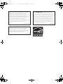
WARNING
VENTILATION CAUTION
To prevent a fire hazard, do not place any naked
flame sources (such as a lighted candle) on the
D3-4-2-1-7a_A_En
equipment.
When installing this unit, make sure to leave space
around the unit for ventilation to improve heat
radiation (at least 60 cm at top, 10 cm at rear, and
30 cm at each side).
Operating Environment
WARNING
Operating environment temperature and humidity:
+5 °C to +35 °C (+41 °F to +95 °F); less than 85 %RH
(cooling vents not blocked)
Do not install this unit in a poorly ventilated area, or in
locations exposed to high humidity or direct sunlight (or
strong artificial light)
D3-4-2-1-7c*_A1_En
Slots and openings in the cabinet are provided for
ventilation to ensure reliable operation of the
product, and to protect it from overheating. To
prevent fire hazard, the openings should never be
blocked or covered with items (such as newspapers,
table-cloths, curtains) or by operating the
equipment on thick carpet or a bed.
D3-4-2-1-7b_A_En
VSX-23TXH_CUXJ.book
4 ページ
2009年5月8日 金曜日 午前10時45分
If the AC plug of this unit does not match the AC
outlet you want to use, the plug must be removed
and appropriate one fitted. Replacement and
mounting of an AC plug on the power supply cord of
this unit should be performed only by qualified
service personnel. If connected to an AC outlet, the
cut-off plug can cause severe electrical shock. Make
sure it is properly disposed of after removal.
The equipment should be disconnected by removing
the mains plug from the wall socket when left unused
for a long period of time (for example, when on
vacation).
CAUTION
The STANDBY/ON switch on this unit will not
completely shut off all power from the AC outlet.
Since the power cord serves as the main disconnect
device for the unit, you will need to unplug it from
the AC outlet to shut down all power. Therefore,
make sure the unit has been installed so that the
power cord can be easily unplugged from the AC
outlet in case of an accident. To avoid fire hazard,
the power cord should also be unplugged from the
AC outlet when left unused for a long period of time
(for example, when on vacation).
D3-4-2-2-1a_A1_En
D3-4-2-2-2a_A_En
WARNING: Handling the cord on this product or
cords associated with accessories sold with the
product will expose you to chemicals listed on
proposition 65 known to the State of California and
other governmental entities to cause cancer and
birth defect or other reproductive harm.
D36-P4_A_En
VSX-23TXH_CUXJ.book
5 ページ
2009年5月8日 金曜日 午前10時45分
Thank you for buying this Pioneer product. Please read through these operating instructions so you will know how to operate
your model properly. After you have finished reading the instructions, put them away in a safe place for future reference.
Contents
Flow of settings on the receiver . . . . . . . . . 7
01 Before you start
Features. . . . . . . . . . . . . . . . . . . . . . . . . . . . . . . . . . . .
Checking what’s in the box . . . . . . . . . . . . . . . . . . . . .
Installing the receiver . . . . . . . . . . . . . . . . . . . . . . . . .
Loading the batteries . . . . . . . . . . . . . . . . . . . . . . . . . .
Operating range of remote control unit . . . . . . . . . . . .
8
9
9
9
9
02 Controls and displays
Remote control . . . . . . . . . . . . . . . . . . . . . . . . . . . . . 10
Front panel . . . . . . . . . . . . . . . . . . . . . . . . . . . . . . . . 12
Display. . . . . . . . . . . . . . . . . . . . . . . . . . . . . . . . . . . . 13
03 Connecting your equipment
Rear panel . . . . . . . . . . . . . . . . . . . . . . . . . . . . . . . . .
Determining the speakers’ application . . . . . . . . . . .
Other speaker connection . . . . . . . . . . . . . . . . . . . .
Placing the speakers . . . . . . . . . . . . . . . . . . . . . . . . .
THX speaker system setup . . . . . . . . . . . . . . . . . . .
Some tips for improving sound quality . . . . . . . . . .
Connecting the speakers . . . . . . . . . . . . . . . . . . . . . .
Installing your speaker system. . . . . . . . . . . . . . . . . .
Standard 5.1/6.1/7.1-channel surround
connections . . . . . . . . . . . . . . . . . . . . . . . . . . . . . .
Bi-amping your speakers. . . . . . . . . . . . . . . . . . . . .
Bi-wiring your speakers . . . . . . . . . . . . . . . . . . . . . .
Selecting the Surr Back system . . . . . . . . . . . . . . . . .
ZONE 2 setup . . . . . . . . . . . . . . . . . . . . . . . . . . . . .
Speaker B setup . . . . . . . . . . . . . . . . . . . . . . . . . . .
Bi-Amping setup . . . . . . . . . . . . . . . . . . . . . . . . . . .
About the audio connection. . . . . . . . . . . . . . . . . . . .
About the video converter . . . . . . . . . . . . . . . . . . . . .
Connecting your TV and playback components . . . . .
Connecting using HDMI . . . . . . . . . . . . . . . . . . . . .
Connecting your DVD player with no HDMI output . . .
Connecting your TV with no HDMI input . . . . . . . . .
Connecting an HDD/DVD recorder, VCR and
other video sources . . . . . . . . . . . . . . . . . . . . . . . . . .
Connecting a satellite/cable receiver or
other set-top box . . . . . . . . . . . . . . . . . . . . . . . . . . . .
Connecting the multichannel analog inputs . . . . . . .
Connecting other audio components. . . . . . . . . . . . .
About the WMA9 Pro decoder. . . . . . . . . . . . . . . . .
Connecting additional amplifiers . . . . . . . . . . . . . . . .
Connecting AM/FM antennas . . . . . . . . . . . . . . . . . .
Connecting external antennas. . . . . . . . . . . . . . . . .
Connecting an XM Radio tuner . . . . . . . . . . . . . . . . .
Connecting a SiriusConnect™ tuner . . . . . . . . . . . . .
MULTI-ZONE setup . . . . . . . . . . . . . . . . . . . . . . . . . .
Making MULTI-ZONE connections. . . . . . . . . . . . . .
Connecting an IR receiver . . . . . . . . . . . . . . . . . . . . .
Operating other Pioneer components with
this unit’s sensor . . . . . . . . . . . . . . . . . . . . . . . . . . . .
15
17
17
18
18
18
19
20
20
21
21
22
22
22
22
22
23
24
24
25
26
28
29
29
29
30
30
31
31
32
32
33
33
35
35
Switching components on and off using
the 12 volt trigger. . . . . . . . . . . . . . . . . . . . . . . . . . . .
Connecting a PC for Advanced MCACC output . . . . .
Connecting an HDMI-equipped component to
the front panel input . . . . . . . . . . . . . . . . . . . . . . . . .
Connecting a component to the front panel inputs . . .
Connecting an iPod . . . . . . . . . . . . . . . . . . . . . . . . . .
Connecting a USB device . . . . . . . . . . . . . . . . . . . . .
Plugging in the receiver. . . . . . . . . . . . . . . . . . . . . . .
36
36
37
38
38
39
39
04 Basic Setup
Switching the speaker impedance. . . . . . . . . . . . . . .
Changing the OSD display language
(OSD Language) . . . . . . . . . . . . . . . . . . . . . . . . . . . .
Automatically setting up for surround sound
(Auto MCACC) . . . . . . . . . . . . . . . . . . . . . . . . . . . . . .
Problems when using the Auto MCACC Setup . . . .
The Input Setup menu . . . . . . . . . . . . . . . . . . . . . . . .
Input function default and possible settings . . . . . .
40
40
41
43
43
44
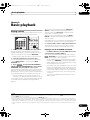
05 Basic playback
Playing a source . . . . . . . . . . . . . . . . . . . . . . . . . . . .
Playing a source with HDMI connection . . . . . . . . .
Selecting the multichannel analog inputs . . . . . . . .
Playing an iPod . . . . . . . . . . . . . . . . . . . . . . . . . . . . .
Playing back audio files stored on an iPod . . . . . . .
Playing a USB device. . . . . . . . . . . . . . . . . . . . . . . . .
Playing back audio files stored
on a USB memory device . . . . . . . . . . . . . . . . . . . .
Playing back photo files stored
on a USB memory device . . . . . . . . . . . . . . . . . . . .
About playable file formats . . . . . . . . . . . . . . . . . . .
Listening to the radio . . . . . . . . . . . . . . . . . . . . . . . . .
Improving FM sound . . . . . . . . . . . . . . . . . . . . . . . .
Using Neural THX . . . . . . . . . . . . . . . . . . . . . . . . . .
Tuning directly to a station . . . . . . . . . . . . . . . . . . .
Saving station presets . . . . . . . . . . . . . . . . . . . . . . .
Naming station presets . . . . . . . . . . . . . . . . . . . . . .
Listening to station presets . . . . . . . . . . . . . . . . . . .
Listening to Satellite Radio . . . . . . . . . . . . . . . . . . . .
Listening to XM Radio . . . . . . . . . . . . . . . . . . . . . . . .
Using XM HD Surround . . . . . . . . . . . . . . . . . . . . .
Saving channel presets . . . . . . . . . . . . . . . . . . . . . .
Using the XM Menu . . . . . . . . . . . . . . . . . . . . . . . .
Listening to SIRIUS Radio . . . . . . . . . . . . . . . . . . . . .
Saving channel presets . . . . . . . . . . . . . . . . . . . . . .
Using the SIRIUS Menu . . . . . . . . . . . . . . . . . . . . .
45
45
46
46
46
48
48
49
50
51
51
51
51
51
51
52
52
52
53
53
54
54
55
55
06 Listening to your system
Auto playback . . . . . . . . . . . . . . . . . . . . . . . . . . . . . .
Listening in surround sound . . . . . . . . . . . . . . . . . . .
Standard surround sound . . . . . . . . . . . . . . . . . . . .
Using the Home THX modes . . . . . . . . . . . . . . . . . .
Using the Advanced surround effects . . . . . . . . . . .
56
56
56
57
58
5
En
VSX-23TXH_CUXJ.book
6 ページ
2009年5月8日 金曜日 午前10時45分
Listening in stereo . . . . . . . . . . . . . . . . . . . . . . . . . . . 58
Using Front Stage Surround Advance . . . . . . . . . . . . 58
Using Stream Direct . . . . . . . . . . . . . . . . . . . . . . . . . . 59
Using surround back channel processing . . . . . . . . . 59
Using the Virtual Surround Back mode . . . . . . . . . . 60
Setting the Up Mix function . . . . . . . . . . . . . . . . . . . . 60
Selecting MCACC presets . . . . . . . . . . . . . . . . . . . . . 61
Choosing the input signal. . . . . . . . . . . . . . . . . . . . . . 61
Better sound using Phase Control . . . . . . . . . . . . . . . 61
07 KURO LINK
Making the KURO LINK connections . . . . . . . . . . . . . 63
Cautions on the KURO LINK function . . . . . . . . . . . 63
About connections with a product of a different
brand that supports the KURO LINK function . . . . . 64
KURO LINK Setup . . . . . . . . . . . . . . . . . . . . . . . . . . . 64
Setting the PQLS function . . . . . . . . . . . . . . . . . . . . . 65
Before using synchronization . . . . . . . . . . . . . . . . . . . 65
Synchronized amp mode . . . . . . . . . . . . . . . . . . . . . . 65
Synchronized amp mode operations . . . . . . . . . . . . 65
Canceling synchronized amp mode . . . . . . . . . . . . . 65
Data Management . . . . . . . . . . . . . . . . . . . . . . . . . . . 88
Renaming MCACC presets . . . . . . . . . . . . . . . . . . . 89
Copying MCACC preset data . . . . . . . . . . . . . . . . . . 89
Clearing MCACC presets . . . . . . . . . . . . . . . . . . . . . 89
11 The system and the other setup
Making receiver settings from the System Setup
menu . . . . . . . . . . . . . . . . . . . . . . . . . . . . . . . . . . . . . 90
Manual speaker setup . . . . . . . . . . . . . . . . . . . . . . . . 90
Surround back speaker setting . . . . . . . . . . . . . . . . 91
Speaker Setting . . . . . . . . . . . . . . . . . . . . . . . . . . . . 91
Channel Level . . . . . . . . . . . . . . . . . . . . . . . . . . . . . 92
Speaker Distance. . . . . . . . . . . . . . . . . . . . . . . . . . . 93
X-Curve . . . . . . . . . . . . . . . . . . . . . . . . . . . . . . . . . . 93
THX Audio Setting . . . . . . . . . . . . . . . . . . . . . . . . . . 93
The Other Setup menu . . . . . . . . . . . . . . . . . . . . . . . . 94
Multi Channel Input Setup . . . . . . . . . . . . . . . . . . . . 94
ZONE Audio Setup . . . . . . . . . . . . . . . . . . . . . . . . . . 95
Power ON Level Setup . . . . . . . . . . . . . . . . . . . . . . . 95
Volume Limit Setup . . . . . . . . . . . . . . . . . . . . . . . . . 95
Remote Control Mode Setup . . . . . . . . . . . . . . . . . . 96
Flicker Reduction Setup . . . . . . . . . . . . . . . . . . . . . . 96
08 Using other functions
Setting the Audio options . . . . . . . . . . . . . . . . . . . . . . 66
Setting the Video options . . . . . . . . . . . . . . . . . . . . . . 68
Switching the speaker system . . . . . . . . . . . . . . . . . . 69
Using the MULTI-ZONE controls . . . . . . . . . . . . . . . . . 69
Making an audio or a video recording. . . . . . . . . . . . . 70
Reducing the level of an analog signal . . . . . . . . . . . . 70
Using the sleep timer . . . . . . . . . . . . . . . . . . . . . . . . . 71
Dimming the display . . . . . . . . . . . . . . . . . . . . . . . . . 71
Switching the HDMI output . . . . . . . . . . . . . . . . . . . . 71
Checking your system settings . . . . . . . . . . . . . . . . . . 71
Resetting the system . . . . . . . . . . . . . . . . . . . . . . . . . 72
Default system settings . . . . . . . . . . . . . . . . . . . . . . 72
09 Controlling the rest of your system
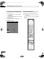
Operating multiple receivers. . . . . . . . . . . . . . . . . . . . 73
Setting the remote to control other components . . . . 73
Selecting preset codes directly . . . . . . . . . . . . . . . . . . 73
Resetting the remote control presets . . . . . . . . . . . . . 74
Default preset codes . . . . . . . . . . . . . . . . . . . . . . . . 74
Controls the components . . . . . . . . . . . . . . . . . . . . . . 74
10 The Advanced MCACC menu
Making receiver settings from the Advanced
MCACC menu . . . . . . . . . . . . . . . . . . . . . . . . . . . . . . 77
Automatic MCACC (Expert) . . . . . . . . . . . . . . . . . . . . 78
Manual MCACC setup . . . . . . . . . . . . . . . . . . . . . . . . 80
Fine Channel Level . . . . . . . . . . . . . . . . . . . . . . . . . . 81
Fine Speaker Distance . . . . . . . . . . . . . . . . . . . . . . . 82
Standing Wave. . . . . . . . . . . . . . . . . . . . . . . . . . . . . 82
Acoustic Calibration EQ Adjust . . . . . . . . . . . . . . . . 83
Acoustic Calibration EQ Professional. . . . . . . . . . . . 83
Checking MCACC Data . . . . . . . . . . . . . . . . . . . . . . . 86
Speaker Setting . . . . . . . . . . . . . . . . . . . . . . . . . . . . 87
Channel Level. . . . . . . . . . . . . . . . . . . . . . . . . . . . . . 87
Speaker Distance . . . . . . . . . . . . . . . . . . . . . . . . . . . 87
Standing Wave. . . . . . . . . . . . . . . . . . . . . . . . . . . . . 87
Acoustic Cal EQ . . . . . . . . . . . . . . . . . . . . . . . . . . . . 87
Output PC . . . . . . . . . . . . . . . . . . . . . . . . . . . . . . . . 88
6
En
12 Additional information
Speaker Setting Guide . . . . . . . . . . . . . . . . . . . . . . . . 97
Positional relationship between speakers and
monitor . . . . . . . . . . . . . . . . . . . . . . . . . . . . . . . . . . 98
Troubleshooting . . . . . . . . . . . . . . . . . . . . . . . . . . . . . 98
Power . . . . . . . . . . . . . . . . . . . . . . . . . . . . . . . . . . . 98
No sound . . . . . . . . . . . . . . . . . . . . . . . . . . . . . . . . . 99
Other audio problems . . . . . . . . . . . . . . . . . . . . . . 100
Video . . . . . . . . . . . . . . . . . . . . . . . . . . . . . . . . . . . 101
Settings . . . . . . . . . . . . . . . . . . . . . . . . . . . . . . . . . 101
Professional Calibration EQ graphical output . . . . 102
Display. . . . . . . . . . . . . . . . . . . . . . . . . . . . . . . . . . 102
Remote control . . . . . . . . . . . . . . . . . . . . . . . . . . . 103
HDMI . . . . . . . . . . . . . . . . . . . . . . . . . . . . . . . . . . . 103
Important information regarding the HDMI
connection. . . . . . . . . . . . . . . . . . . . . . . . . . . . . . . 104
USB interface . . . . . . . . . . . . . . . . . . . . . . . . . . . . 105
XM radio messages . . . . . . . . . . . . . . . . . . . . . . . . 105
SIRIUS radio messages . . . . . . . . . . . . . . . . . . . . . 106
Surround sound formats . . . . . . . . . . . . . . . . . . . . . 107
Dolby . . . . . . . . . . . . . . . . . . . . . . . . . . . . . . . . . . . 107
DTS . . . . . . . . . . . . . . . . . . . . . . . . . . . . . . . . . . . . 108
Windows Media Audio 9 Professional . . . . . . . . . . 108
About iPod . . . . . . . . . . . . . . . . . . . . . . . . . . . . . . . . 108
About THX . . . . . . . . . . . . . . . . . . . . . . . . . . . . . . . . 109
About Neural – THX Surround . . . . . . . . . . . . . . . . . 110
About SIRIUS and XM . . . . . . . . . . . . . . . . . . . . . . . 111
Auto Surround, ALC and Stream Direct with
different input signal formats . . . . . . . . . . . . . . . . . . 112
Preset code list. . . . . . . . . . . . . . . . . . . . . . . . . . . . . 113
Specifications. . . . . . . . . . . . . . . . . . . . . . . . . . . . . . 119
Cleaning the unit . . . . . . . . . . . . . . . . . . . . . . . . . . . 119
Our philosophy . . . . . . . . . . . . . . . . . . . . . . . . . . . . . 119
Index . . . . . . . . . . . . . . . . . . . . . . . . . . . . . . . . . . . . 120
VSX-23TXH_CUXJ.book
7 ページ
2009年5月8日 金曜日 午前10時45分
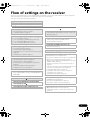
Flow of settings on the receiver
The unit is a full-fledged AV receiver equipped with an abundance of functions and terminals. It can be used easily
after following the procedure below to make the connections and settings.
The colors of the steps indicate the following:
Required setting item
Setting to be made as necessary
1
Before you start
• Checking what’s in the box (page 9)
• Loading the batteries (page 9)
2
•
•
•
•
Determining the speakers’ application (page 17)
7.1ch surround connection
5.1ch surround & Front Bi-amping connection
5.1ch surround & ZONE 2 connection
5.1ch surround & Speaker B connection
3
Connecting the speakers
• Placing the speakers (page 18)
• Connecting the speakers (page 19)
• Standard 5.1/6.1/7.1-channel surround connections
(page 20)
• Bi-amping your speakers (page 21)
4
•
•
•
•
•
Connecting the components
About the audio connection (page 22)
About the video converter (page 23)
Connecting your TV and playback components
(page 24)
Connecting AM/FM antennas (page 31)
Plugging in the receiver (page 39)
5
Switching the speaker impedance (page 40)
(Only if the impedance of the connected speakers is
6 Ω to 8 Ω)
9
MCACC speaker settings
• Automatically setting up for surround sound (Auto
MCACC) (page 41)
10 The Input Setup menu (page 43)
(When using connections other than the
recommended connections)
11 Switching the HDMI output (page 71)
(VSX-23TXH model only)
12 Basic playback (page 45)
13
•
•
•
•
•
•
•
•
•
6
Power On
7
Changing the OSD display language (OSD
Language) (page 40)
8
Surround back speaker setting (page 91)
Adjusting the sound and picture quality as desired
Using the various listening modes
Using surround back channel processing (page 59)
Better sound using Phase Control (page 61)
Measure the all EQ type (SYMMETRY/ALL CH ADJ/
FRONT ALIGN) (page 78)
Change the channel level while listening (Tip on
page 92)
Switches on/off the Acoustic Calibration EQ, Sound
retriever or Dialog Enhancement (page 66)
Setting the PQLS function (page 65)
Setting the Audio options (Tone, Loudness or
Sound delay, etc.) (page 66)
Setting the Video options (page 68)
14
•
•
•
Other optional adjustments and settings
KURO LINK Setup (page 64)
The Advanced MCACC menu (page 77)
The system and the other setup (page 90)
15 Making maximum use of the remote control
• Operating multiple receivers (page 73)
• Setting the remote to control other components
(page 73)
7
En
VSX-23TXH_CUXJ.book
01
8 ページ
2009年5月8日 金曜日 午前10時45分
Before you start
Chapter 1:
Before you start
Features
• Advanced Direct Energy design
This receiver offers a new advancement in discrete
design unique to Pioneer for high-power drivability, low
distortion and stable imaging. Through a circuit design
that minimizes the energy loss of the amplifier for each of
the channels, this receiver generates equal amplifier
power to all channels, eliminating the possibility of one
channel dominating a particular sound field.
• Easy setup using Advanced MCACC
The Auto MCACC Setup provides a quick but accurate
surround sound setup, which includes the advanced
features of Professional Acoustic Calibration EQ. This
innovative technology measures the reverb
characteristics of your listening area, allowing you to
customize your system calibration with the help of a
graphical output that can be displayed on-screen or
using computer. With the additional benefits of
numerous MCACC preset memories, standing wave
control and microphone measurements from a series of
reference points, your home theater experience can be
truly customized for optimal surround sound.
• THX Select2 Plus certified design
This receiver bears the THX Select2 Plus logo, which
means it has passed a rigorous series of quality and
performance tests covering every aspect of the product.
This includes testing of pre-amplifier and power amplifier
performance and operation, and hundreds of other
parameters in both the digital and analog domain,
making your home theater experience as faithful as
possible to what the director intended.
• Dolby Digital and DTS decoding, including Dolby
Digital EX, Dolby Pro Logic IIx, DTS 96/24, DTS-ES, Dolby
Digital Plus, Dolby TrueHD, DTS-EXPRESS and DTS-HD
Master Audio
Dolby Digital and DTS decoding brings theater sound
right into your home with up to six channels of surround
sound, including a special LFE (Low Frequency Effects)
channel for deep, realistic sound effects.
The built-in Dolby Pro Logic IIx and DTS Neo:6 decoders
not only provide full surround sound decoding for Dolby
Surround sources, but will also generate convincing
surround sound for any stereo source.
Also, with the addition of a surround back speaker, you
can take advantage of the built-in Dolby Digital EX and
DTS-ES decoders for six-channel surround sound.
8
En
Furthermore, Dolby Digital Plus and Dolby TrueHD,
which are designed for the next-generation highdefinition media such as Blu-ray Disc and HD DVD,
support up to 7.1 channels and 8 channels respectively.
DTS-EXPRESS is a low-bitrate encoding technology
supporting up to 5.1 channels, with fixed data transfer
rates ranging from 24 kbps to 256 kbps (this encoding is
available only when signals are delivered to this receiver
as primary audio).
DTS-HD Master Audio delivers audio signals to listeners
without any loss of data with its high transfer rates.
• Phase Control
The Phase Control technology incorporated into this
receiver’s design provides coherent sound reproduction
through the use of phase matching for an optimal sound
image at your listening position.
• Sound Retriever
The Sound Retriever feature employs DSP technology to
restore sound pressure and smooth jagged artifacts left
over after compression. This helps bring CD quality
sound back to WMA and MP3 audio files and achieves a
richer sense of presence when playing Dolby Digital, DTS
or WMA 9 Pro audio formats recorded in multiple
channels on DVDs and other discs.
• Front Stage Surround Advance
With the Front Stage Surround Advance feature, you can
enjoy seamless, natural surround sound effects using
only the front speakers, without deteriorating the quality
of the original sound.
• Auto Level Control
When the source is played in Auto level control mode
(ALC), this receiver automatically equalizes the playback
sound level according to the variation in recording levels.
• HDMI and digital video conversion
This receiver is compatible with the HDMI digital video
format, providing you with high-definition digital video/
audio via a single cable.
High-quality sound formats such as DTS-HD and Dolby
TrueHD are supported while this receiver is also
compatible with the Deep Color feature. You can operate
this receiver in synchronization with your Pioneer
component that supports the KURO LINK function by
connecting your component to this receiver via HDMI.
Also, the built-in digital video converter of this receiver
makes both de-interlacing and up-scaling possible, and
analog video signals being input are converted and
output as digital video signals at the HDMI terminal.
VSX-23TXH_CUXJ.book
9 ページ
2009年5月8日 金曜日 午前10時45分
Before you start
• XM and SIRIUS Ready
With the XM and SIRIUS Radio terminals, you’ll be up
and running in no time. This receiver’s enhanced
compatibility makes XM HD Surround playback as well
as on-screen control of your XM and SIRIUS Radio an
added possibility.
01
Loading the batteries
• iPod/iPhone and USB Ready
This receiver has the terminals for connecting an iPod/
iPhone unit and a USB mass storage device.
The iPod terminal is ready for handling digital audio and
video, and this receiver’s enhanced compatibility makes
on-screen control of your iPod an added possibility.
The USB terminal allows you to listen to two-channel
audio from a USB mass storage device connected to this
receiver.
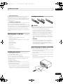
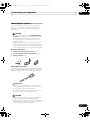
Checking what’s in the box
Please check that you’ve received the following supplied
accessories:
• Setup microphone (cable: 5 m (16.4 ft.))
• Remote control unit
• AA size IEC R6 dry cell batteries (to confirm system
operation) x2
• AM loop antenna
• FM wire antenna
• iPod cable
CAUTION
Incorrect use of batteries may result in such hazards as
leakage and bursting. Observe the following precautions:
• Never use new and old batteries together.
• Insert the plus and minus sides of the batteries
properly according to the marks in the battery case.
• Batteries with the same shape may have different
voltages. Do not use different batteries together.
• When disposing of used batteries, please comply
with governmental regulations or environmental
public instruction’s rules that apply in your country or
area.
• WARNING
Do not use or store batteries in direct sunlight or
other excessively hot place, such as inside a car or
near a heater. This can cause batteries to leak,
overheat, explode or catch fire. It can also reduce the
life or performance of batteries.
• Power cord
• Warranty card
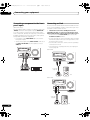
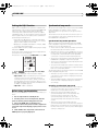
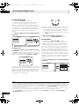
Operating range of remote control unit
• These operating instructions
The remote control may not work properly if:
• There are obstacles between the remote control and
the receiver’s remote sensor.
Installing the receiver
• When installing this unit, make sure to put it on a
level and stable surface.
Don’t install it on the following places:
– on a color TV (the screen may distort)
– near a cassette deck (or close to a device that gives off
a magnetic field). This may interfere with the sound.
– in direct sunlight
– in damp or wet areas
– in extremely hot or cold areas
– in places where there is vibration or other movement
– in places that are very dusty
– in places that have hot fumes or oils (such as a kitchen)
• Do not touch this receiver’s bottom panel while the
power is turned on. The bottom panel gets hot when
the power is on, and touching it could cause burns.
• Direct sunlight or fluorescent light is shining onto the
remote sensor.
• The receiver is located near a device that is emitting
infrared rays.
• The receiver is operated simultaneously with another
infrared remote control unit.
30°
30°
7 m (23 ft.)
9
En
VSX-23TXH_CUXJ.book
02
10 ページ
2009年5月8日 金曜日 午前10時45分
Controls and displays
Chapter 2:
Controls and displays
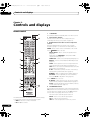
Remote control
RECEIVER
DVD
BD
DVR
HDMI
TV
CD
CD-R
VIDEO
XM
SIRIUS
iPod USB TUNER
INPUT
SELECT
3
13
2 Input function buttons
Press to select control of other components (see
Controlling the rest of your system on page 73).
2
3
SIGNAL SEL
MCACC
SLEEP
ENTER can be used to enter commands for TV or DTV.
4
5
6
SBch
A.ATT
DIMMER
7
8
D.ACCESS
CH LEVEL
CLASS
0
ENTER
INPUT
MASTER
VOLUME
Press RECEIVER first to access:
INPUT SELECT – Use to select the input function
(page 45).
9
14
TV CONTROL
CH
3 Number buttons and other receiver/component
controls
Use the number buttons to directly select a radio
frequency (page 51) or the tracks on a CD, DVD, etc.
HDMI OUT
1
4
1 RECEIVER
This switches between standby and on for this receiver.
SOURCE
1
2
12
VOL
MUTE
15
AUDIO
PARAMETER
TUNE
LIST
5
6
VIDEO
PARAMETER
TOOLS
TOP MENU
BAND
T.EDIT
GUIDE
ENTER
PRESET
PRESET
CATEGORY
RETURN
HOME
MENU
TUNE
iPod CTRL
AUTO/ALC/
MENU
DIRECT STEREO STANDARD ADV SURR
HDD
7
8
DVD
THX
PHASE CTRL
ANT
MPX
AUDIO
INFO
STATUS
PQLS
MEMORY
CH
DISP
TV CTRL RECEIVER
9
10
11
REMOTE
SETUP
ZONE 2
MAIN
16
17
ZONE 3
RECEIVER
VSX-23TXH only: HDMI OUT – Switch the HDMI
output terminal (page 71).
SIGNAL SEL – Use to select an input signal (page 61).
MCACC – Press to switch between MCACC presets
(page 61).
SLEEP – Use to put the receiver in sleep mode and
select the amount of time before sleep (page 71).
SBch – Use to select the surround back/virtual surround
back channel mode (page 59).
A.ATT – Attenuates (lowers) the level of an analog
input signal to prevent distortion (page 70).
DIMMER – Dims or brightens the display (page 71).
CH LEVEL – Press repeatedly to select a channel,
then use / to adjust the level (page 92).
Press TUNER first to access:
D.ACCESS – After pressing, you can access a radio
station directly using the number buttons (page 51).
CLASS – Switches between the seven banks (classes)
of radio station presets (page 51).
4 TV CONTROL buttons
These buttons are dedicated to control the TV assigned to
TV operation selector switch. Thus if you only have one TV
to hook up to this system assign it to the TV operation
selector switch (see page 74 for more on this).
– Use to turn on/off the power of the TV.
INPUT – Use to select the TV input signal.
The remote has been conveniently color-coded according
to component control using the following system:
• White – Receiver control, TV Control
• Blue – Other controls
10
En
CH +/– – Use to select channels.
VOL +/– – Use to adjust the volume on your TV.
VSX-23TXH_CUXJ.book
11 ページ
2009年5月8日 金曜日 午前10時45分
Controls and displays
5 Tuner/component control buttons/HOME MENU
These button controls can be accessed after you have
selected the corresponding input function button (DVD,
DVR, TV, etc.). The BAND and T.EDIT tuner controls are
explained on page 51.
Press RECEIVER first to access:
AUDIO PARAMETER – Use to access the Audio
options (page 66).
VIDEO PARAMETER – Use to access the Video
options (page 68).
HOME MENU – Use to access the Home Menu
(pages 40, 43, 64, 77, 90 and 94).
RETURN – Press to confirm and exit the current
menu screen (also use to return to the previous menu
with DVDs or to select closed captioning with DTV).
6 /// (TUNE/PRESET) /ENTER
Use the arrow buttons when setting up your surround
sound system (see page 77) and the Audio or Video
options (page 66 or 68). Also used to control DVD menus/
options and for deck 1 of a double cassette deck player.
Use TUNE/ to find radio frequencies and use PRESET
/ to find preset stations (page 51).
7 Component/Receiver control buttons
The main buttons (, , etc.) are used to control a
component after you have selected it using the input
function buttons.
The controls above these buttons can be accessed after
you have selected the corresponding input function
button (for example DVD, DVR or TV). These buttons also
function as described below.
Press TUNER first to access:
MPX – Switches between stereo and mono reception
of FM broadcasts. If the signal is weak, then switching
to mono will improve the sound quality (page 51).
Press RECEIVER first to access:
AUTO/ALC/DIRECT – Switches between Auto
Surround (page 56), Auto level control mode and
Stream Direct mode (page 59).
02
8
AUDIO – Changes the audio or channel on DVD or
BD discs.
DISP – Switches between named station presets and
radio frequencies.
CH +/– – Use to select channels for DVD/DVR units.
9 REMOTE SETUP
Use to input the preset code when making remote
control settings and to set the remote control mode
(page 73).
10 TV CTRL
Use this button to set preset code of your TV’s
manufacturer when controlling TV (see Selecting preset
codes directly on page 73 for more on this).
11 MULTI-ZONE operation selector switch
Switch to perform operations in the main zone, ZONE 2
and ZONE 3 (VSX-23TXH only) (page 70).
12 Remote control LED
Lights when a command is sent from the remote control
(page 73).
13 SOURCE
Press to turn on/off other components connected to the
receiver (see page 73 for more on this).
14 MASTER VOLUME +/–
Use to set the listening volume.
15 MUTE
Mutes the sound or restores the sound if it has been
muted (adjusting the volume also restores the sound).
16 RECEIVER
Switches the remote to control the receiver (used to
select the white commands above the number buttons
(A.ATT, etc.)). Also use this button to set up surround
sound.
17
Press to turn on/off the illumination of some of the
buttons.
STEREO – Switches between stereo playback and
Front Stage Surround Advance modes (page 58).
STANDARD – Press for Standard decoding and to
switch between the various 2 Pro Logic IIx and
Neo:6 options (page 56).
ADV SURR – Use to switch between the various
surround modes (page 58).
THX – Press to select a Home THX listening mode
(page 57).
PHASE CTRL – Press to switch on/off Phase Control
(page 61).
STATUS – Press to check selected receiver settings
(page 71).
PQLS – Press to select PQLS setting (page 65).
11
En
VSX-23TXH_CUXJ.book
12 ページ
2009年5月8日 金曜日 午前10時45分
Controls and displays
02
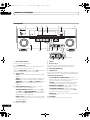
Front panel
1
2
3
4
5
6
7
8
VSX-23TXH
STANDBY/ON
ENTER
BAND
TUNE
TUNE
PHASE
CONTROL
AUTO SURR /ALC/
STREAM DIRECT
INPUT
SELECTOR
ADVANCED
MCACC
STEREO
ADVANCED
SURROUND
PQLS
STANDARD
SURROUND
HOME THX
HDMI
PRESET
PRESET
TUNER EDIT
MASTER
VOLUME
MULTI-ZONE
CONTROL
ON / OFF
SPEAKERS
PHONES
VIDEO CAMERA
iPod
iPhone
USB
MCACC SETUP MIC
9
10
11 12 13
14
USB
iPod
iPhone
VIDEO
HDMI 4
15
VIDEO 2 INPUT
L AUDIO
R
VSX-23TXH
MCACC
SETUP MIC
VSX-21TXH
14
1 INPUT SELECTOR dial
Use to select an input function.
2 STANDBY/ON
Switches the receiver between on and standby. Power
indicator lights when the receiver is on.
When the KURO LINK function is set to ON, the power
indicator lights when the power is in standby.
3
4
Tuner controls
BAND – Switches between AM and FM radio bands
(page 51).
TUNE +/– – Use to find radio frequencies (page 51).
PRESET +/– – Use to find preset stations (page 51).
TUNER EDIT – Use with TUNE +/–, PRESET +/– and
ENTER to memorize and name stations for recall
(page 51).
PHASE CONTROL indicator – Lights to indicate
Phase Control is selected (page 61).
ADVANCED MCACC indicator – Lights when EQ is
set to ON in the AUDIO PARAMETER menu (page 66).
VSX-23TXH only: PQLS indicator – Lights when the
PQLS feature is active (page 65).
HDMI indicator – Blinks when connecting an HDMIequipped component; lights when the component is
connected (page 24).
5 Character display
See Display on page 13.
12
En
6
16
13
ENTER
7 Remote sensor
Receives the signals from the remote control (see
Operating range of remote control unit on page 9).
8
MASTER VOLUME dial
9 PHONES jack
Use to connect headphones. When the headphones are
connected, there is no sound output from the speakers.
10 Listening mode buttons
AUTO SURR/ALC/STREAM DIRECT – Switches
between Auto Surround (page 56), Auto level control
mode and Stream Direct mode (page 59).
STEREO – Switches between stereo playback and
Front Stage Surround Advance modes (page 58).
ADVANCED SURROUND – Use to switch between
the various surround modes (page 58).
STANDARD SURROUND – Press for Standard
decoding and to switch between the various 2 Pro
Logic IIx and Neo:6 options (page 56).
HOME THX – Press to select a Home THX listening
mode (page 57).
11 SPEAKERS
Use to change the speaker system (page 69).
VSX-23TXH_CUXJ.book
13 ページ
2009年5月8日 金曜日 午前10時45分
Controls and displays
02
12 MULTI-ZONE controls
If you’ve made MULTI-ZONE connections (see MULTIZONE setup on page 33) use these controls to control the
sub zone from the main zone (see Using the MULTI-ZONE
controls on page 69).
13 MCACC SETUP MIC jack
Use to connect the supplied microphone (page 41).
14 iPod/iPhone/USB terminals
Use to connect your Apple iPod as an audio and video
source, or connect a USB device for audio and photo
playback (page 38).
15 VSX-23TXH only: HDMI 4 input connector
Use for connection to compatible HDMI device (Video
camera, etc.). See Connecting an HDMI-equipped
component to the front panel input on page 37.
16 VSX-21TXH only: VIDEO 2 INPUT terminals
Use to connect your portable equipment such as
camcorders, video games and portable audio/video
equipment. See Connecting a component to the front
panel inputs on page 38.
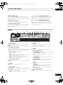
Display
1
AUTO
PCM
HDMI
DIGITAL
ANALOG
2
L
SL
XL
C
XC
LFE
3
45
R 2DIGITAL PLUS
2TrueHD WMA9Pro
SR DTS HD ES 96/24
XR
MSTR
AUTO SURROUND
STREAM DIRECT
CD
CD-R
TUNER
6
7
8
9 10 11
12
13
14
DSD PCM
TUNED
MULTI-ZONE PQLS ALC ATT STEREO
S.RTRV SOUND UP MIX OVER MONO
DVD TV
BD DVR
SIRIUS
iPod
VIDEO
HDMI
15 16
dB
USB XM
[2] [3] [4]
2PROLOGIC x Neo:6
THX ADV.SURROUND
STEREO STANDARD
SP AB
SLEEP
9
17
18 19 20
21
22
1 SIGNAL indicators
Light to indicate the currently selected input signal.
AUTO lights when the receiver is set to select the input
signal automatically (page 61).
7 SOUND
Lights when any of the Midnight, Loudness or tone
controls feature is selected (page 66).
2 Program format indicators
Light to indicate the channels being input when PCM
signals are being input. They do not indicate the audio
signals being output from the receiver.
8 UP MIX
Lights when the Up Mix is switched on (page 60).
L/R – Left front/Right front channel
C – Center channel
SL/SR – Left surround/Right surround channel
LFE – Low frequency effects channel (the (( )) indicators light
when an LFE signal is being input)
XL/XR – Two channels other than the ones above
XC – Either one channel other than the ones above, the mono
surround channel or matrix encode flag
3 Digital format indicators
Light when a signal encoded in the corresponding format
is detected.
4 S.RTRV
Lights when the Sound Retriever function is active
(page 66).
5 MULTI-ZONE
Lights when the MULTI-ZONE feature is active (page 69).
6
DSD PCM – Light during DSD (Direct Stream Digital) to
PCM conversion with SACDs.
PCM – Lights during playback of PCM signals.
Lights when Dialog Enhancement is switched on.
9
Listening mode indicators
AUTO SURROUND – Lights when the Auto Surround
feature is switched on (page 56).
ALC – Lights when the ALC (Auto level control) mode
is selected (page 59).
STREAM DIRECT – Lights when Direct/Pure Direct is
selected (page 59).
ADV.SURROUND – Lights when one of the
Advanced Surround modes has been selected
(page 58).
STEREO – Lights when stereo listening is switched
on (page 58).
STANDARD – Lights when one of the Standard
Surround modes is switched on (page 56).
THX – Lights when one of the Home THX modes is
selected (page 57).
10
(PHASE CONTROL)
Lights when the Phase Control is switched on (page 61).
13
En
VSX-23TXH_CUXJ.book
02
14 ページ
2009年5月8日 金曜日 午前10時45分
Controls and displays
11 Analog signal indicators
Light to indicate reducing the level of an analog signal
(page 70).
12 Tuner indicators
TUNED – Lights when a broadcast is being received.
STEREO – Lights when a stereo FM broadcast is being
received in auto stereo mode.
MONO – Lights when the mono mode is set using
MPX.
13
Lights when the sound is muted (page 11).
14 Master volume level
Shows the overall volume level.
“---” indicates the minimum level, and “+12dB” indicates
the maximum level.
15 Input function indicators
Light to indicate the input function you have selected.
16 Scroll indicators
Light when there are more selectable items when making
the various settings.
17 Speaker indicators
Lights to indicate the current speaker system, A and/or B
(page 69).
18 SLEEP
Lights when the receiver is in sleep mode (page 71).
19 Matrix decoding format indicators
2PRO LOGIC IIx – This lights to indicate 2 Pro
Logic II / 2 Pro Logic IIx decoding (page 56).
Neo:6 – When one of the Neo:6 modes of the receiver
is on, this lights to indicate Neo:6 processing (page 56).
20 MSTR
Lights during playback of DTS-HD Master Audio signal.
21 Character display
Displays various system information.
22 Remote control mode indicator
Lights to indicate the receiver’s remote control mode
setting. (Not displayed when set to 1.) (page 73)
14
En
VSX-23TXH_CUXJ.book
15 ページ
2009年5月8日 金曜日 午前10時45分
Connecting your equipment
03
Chapter 3:
Connecting your equipment
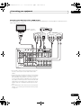
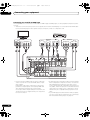
This receiver provides you with many connection possibilities, but it doesn’t have to be difficult. This page explains the
kinds of components you can connect to make up your home theater system.
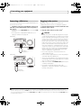
Important
• Illustration shows the VSX-23TXH, however connections for the VSX-21TXH are the same except where noted.
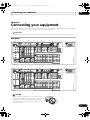
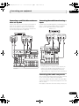
Rear panel
HDMI
1
BD IN
ASSIGNABLE
1 3
6
IN 1
OUT 1 (KURO
LINK)
IN 3
IN 2
2
COAXIAL
OUT 2
IN 2 L
(DVR)
Y
IN 2
3
ASSIGNABLE
IN 1
OUT
IN 3
IN 2
OPTICAL
4
XM
5
SIRIUS
IN
IN
COMPONENT
VIDEO
ASSIGNABLE
IN 1
(DVD)
Y
ASSIGNABLE
IN 1
7
9
(DVD)
10
(CD)
(TV/SAT)
11
FRONT
(DVR)
(VIDEO)
CENTER
SURROUND
12
FRONT
13ANTENNA
AUDIO
CENTER
R
PR
PR
Y
MONITOR
OUT
AC IN
19
AC IN
FM UNMAL
75 ޓޓ
L
(Single)
R
AM LOOP
PB
PB
19
ZONE2
ZONE3
DVD
TV/SAT
VIDEO
OUT
OUT
MONITOR
OUT
IN
IN
IN
8
DVR
OUT
CD
IN
CD-R/TAPE
IN
OUT
SUBWOOFER SURROUND SURROUND
BACK
SUBWOOFER
IN
MULTI CH IN
PRE OUT
VIDEO
SPEAKERS
18
A
R
PB
FRONT
CENTER
L
R
SURROUND
L
R
SURROUND BACK /
B
L
(Single)
S-VIDEO
15CONTROL 16
PR
14
IN
RS-232C
12 V TRIGGER
17
IR
IN 1
OUT
IN 2 OUT
(OUTPUT 12 V
TOTAL 50 mA MAX)
1
2
VSX-23TXH
HDMI
1
BD IN
ASSIGNABLE
1 3
6
IN 1
IN 3
IN 2
2
COAXIAL
OUT
ASSIGNABLE
IN 1
(DVD)
Y
IN 2 L
(DVR)
Y
ASSIGNABLE
IN 1
IN 2
3
ASSIGNABLE
IN 1
OUT
IN 3
IN 2
OPTICAL
4
XM
5
SIRIUS
IN
IN
COMPONENT
VIDEO
7
9
(DVD)
10
(CD)
(TV/SAT)
11
FRONT
(DVR)
(VIDEO)
CENTER
SURROUND
12
FRONT
13ANTENNA
AUDIO
CENTER
FM UNMAL
75 ޓޓ
L
(Single)
R
R
AM LOOP
PB
PB
PR
PR
Y
MONITOR
OUT
ZONE2
DVD
TV/SAT
VIDEO
OUT
IN
IN
IN
8
DVR
OUT
CD
IN
CD-R/TAPE
IN
OUT
SUBWOOFER SURROUND SURROUND
BACK
SUBWOOFER
IN
MULTI CH IN
MONITOR
OUT
PRE OUT
VIDEO
SPEAKERS
18
A
R
PB
FRONT
L
CENTER
R
SURROUND
L
R
SURROUND BACK /
B
L
(Single)
S-VIDEO
15CONTROL 16
PR
14
RS-232C
IN
OUT
12 V TRIGGER
17
IR
IN
OUT
(OUTPUT 12 V
TOTAL 50 mA MAX)
1
2
VSX-21TXH
CAUTION
• Before making or changing the connections, switch
off the power and disconnect the power cord from the
power outlet. Plugging in should be the final step.
• To avoid hum, do not lay connected cables over the
top of the receiver.
15
En
VSX-23TXH_CUXJ.book
16 ページ
2009年5月8日 金曜日 午前10時45分
Connecting your equipment
03
1 HDMI connectors (x6 (VSX-23TXH)/x5 (VSX-21TXH))
Multiple inputs and one (VSX-21TXH)/two (VSX-23TXH)
output(s) for high-quality audio/video connection to
compatible HDMI devices.
See Connecting your TV and playback components on
page 24.
VSX-23TXH only: See Switching the HDMI output on
page 71.
2 Coaxial digital audio inputs (x2)
Use for digital audio sources, including DVD players/
recorders, digital satellite receivers, CD players, etc.
See also The Input Setup menu on page 43 to assign
the inputs.
3 Optical digital audio output/input(s) (x4)
Use the OUT jack for recording to a CD or MiniDisc
recorder.
See Connecting other audio components on page 29.
Use the IN jacks for digital audio sources, including DVD
players/recorders, digital satellite receivers, CD players,
etc.
See also The Input Setup menu on page 43 to assign
the inputs.
4
XM Radio input
See Connecting an XM Radio tuner on page 32.
5 SIRIUS Radio input
See Connecting a SiriusConnect™ tuner on page 32.
6 Component video connectors (x3)
Use the inputs to connect any video source that has
component video output, such as a DVD player.
See Connecting your DVD player with no HDMI output
on page 25.
Use the output to connect monitor or TV.
See Connecting your TV with no HDMI input on
page 26.
7 ZONE 2 and ZONE 3 (VSX-23TXH only) output(s)
Use to connect a second or third (VSX-23TXH only)
amplifier and monitors or TVs in a separate room.
See MULTI-ZONE setup on page 33.
8 Composite and S-Video monitor outputs
Use to connect monitors and TVs.
See Connecting your TV with no HDMI input on
page 26.
9 Audio/video source inputs/(outputs) (x5)
Use for connection to audio/visual sources, such as DVD
players/recorders, VCRs, etc. Each set of inputs has jacks
for composite video, S-Video and stereo analog audio.
See Connecting an HDD/DVD recorder, VCR and other
video sources on page 28.
10 Stereo analog audio source inputs/(outputs) (x3)
Use for connection to audio sources such as CD players,
tape decks, turntables, etc.
See Connecting other audio components on page 29.
16
En
11 Multichannel analog audio inputs
7.1 channel inputs for connection to a DVD player with
multichannel analog outputs.
See Connecting the multichannel analog inputs on
page 29.
12 Multichannel pre-amplifier outputs
Use to connect separate amplifiers for front, center,
surround, surround back and subwoofer channels.
See Connecting additional amplifiers on page 30 (see
also Installing your speaker system on page 20 for
powered subwoofer connection).
13 AM and FM antenna terminals
Use to connect indoor or outdoor antennas for radio
broadcasts.
See Connecting AM/FM antennas on page 31.
14 RS-232C connector
Use for connection to a PC for graphical output when
using Advanced MCACC.
See Connecting a PC for Advanced MCACC output on
page 36.
15 Control input/output
Use to connect other Pioneer components so that you
can control all your equipment from a single IR remote
sensor.
See Operating other Pioneer components with this
unit’s sensor on page 35.
16 Remote input(s)/output (x3 (VSX-23TXH)/x2 (VSX21TXH))
Use for connection to an external remote control sensor
for use in a MULTI-ZONE setup, for example.
See Connecting an IR receiver on page 35.
17 12 V trigger jacks (total 50 mA max.) (x2)
Use to switch components in your system on and off
according to the input function of the receiver.
See Switching components on and off using the 12
volt trigger on page 36.
18 Speaker terminals
Use for connection to the main front, center, surround
and surround back speakers.
See Connecting the speakers on page 19.
19 AC power inlet
Connect the supplied power cord here.
See Plugging in the receiver on page 39.
VSX-23TXH_CUXJ.book
17 ページ
2009年5月8日 金曜日 午前10時45分
Connecting your equipment
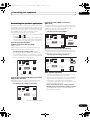
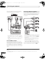
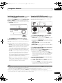
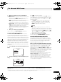
Determining the speakers’ application
Surround sound with a strong sense of presence can be
enjoyed by connecting 7 speakers and 1 subwoofer. It is
also possible to achieve high sound quality using bi-amp
connections and to enjoy music in other rooms using the
MULTI-ZONE feature. High sound quality can be
achieved with a minimum of two speakers.
• Be sure to connect speakers to the front left and right
channels ( L and R ).
• The Surr Back System setting must be made if you
use any of the connections shown below other than
[1] (see Selecting the Surr Back system on page 22).
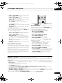
[1] 7.1ch surround connection
(Simple connection & Best surround)
*Default setting
These connections prioritize surround sound with a
speaker layout like that in a movie theater.
• Surr Back System setting: Normal (default)
• If you have six speakers, either only connect one
surround back speaker (6.1 ch surround), or connect
for the 7.1-channel setting as shown on the diagram
below but without the center speaker.
03
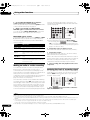
[3] 5.1ch surround & ZONE 2 connection
(Multi Zone)
With these connections you can simultaneously enjoy
5.1-channel surround sound in the main zone with stereo
playback on another component in ZONE 2. (The
selection of input devices is limited.)
• Surr Back System setting: ZONE 2
L
L
R
SW
C
Front
right
Center
Subwoofer
SR
SL
Surround
left
Surround
right
SBL
SBR
Surround
back left
• Surr Back System setting: Front Bi-Amp
R
SW
C
Center
L
R
Left
Right
ZONE 2
Surround
right
Surround
left
SR
SL
[4] 5.1ch surround & Speaker B connection
With these connections you can simultaneously enjoy
5.1-channel surround sound in the main zone with stereo
playback of the same sound on the B speakers.
• Surr Back System setting: Speaker B
R
SW
Front
left
C
Center
Speaker B
Front
right
Subwoofer
Surround
left
SL
Surround
right
SR
• Your favorite speaker connections can be selected
even if you have fewer than 5.1 speakers.
Bi-amping connection of the front speakers for high
sound quality with 5.1-channel surround sound.
L
Center
Front
right
Other speaker connection
Surround
back right
[2] 5.1ch surround & Front Bi-amping connection
(High quality surround)
Front
left*
C
Subwoofer
L
Front
left
R
SW
Front
left
Front
right*
• When not connecting a subwoofer, connect speakers
with low frequency reproduction capabilities to the
front channel. (The subwoofer’s low frequency
component is played from the front speakers, so the
speakers could be damaged.)
• After connecting, be sure to conduct the Auto
MCACC (speaker environment setting) procedure.
See Automatically setting up for surround sound
(Auto MCACC) on page 41.
Subwoofer
Surround
left
SL
Surround
right
SR
*Bi-amp compatible speaker
17
En
VSX-23TXH_CUXJ.book
03
18 ページ
2009年5月8日 金曜日 午前10時45分
Connecting your equipment
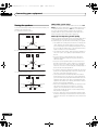
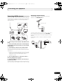
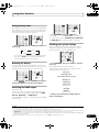
THX speaker system setup
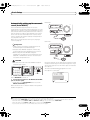
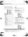
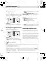
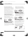
Placing the speakers
To achieve the best possible surround sound, install your
speakers as shown below.
5.1 channel surround system:
Center
Front right
Front left
Where you put your speakers in the room has a big effect
on the quality of the sound. The following guidelines
should help you to get the best sound from your system.
120°
120°
Surround
right
Surround
left
6.1 channel surround system:
Center
Front right
• The subwoofer can be placed on the floor. Ideally, the
other speakers should be at about ear-level when
you’re listening to them. Putting the speakers on the
floor (except the subwoofer), or mounting them very
high on a wall is not recommended.
• For the best stereo effect, place the front speakers 2
m to 3 m (6 ft. to 9 ft.) apart, at equal distance from
the TV.
• If you’re using a center speaker, place the front
speakers at a wider angle. If not, place them at a
narrower angle.
Subwoofer
120°
120°
Surround
left
Surround
right
Surround Back
Center
Front right
Front left
Subwoofer
90°
90°
Surround
left
Surround
right
60°
• Place the center speaker above or below the TV so
that the sound of the center channel is localized at
the TV screen. Also, make sure the center speaker
does not cross the line formed by the leading edge of
the front left and right speakers.
• It is best to angle the speakers towards the listening
position. The angle depends on the size of the room.
Use less of an angle for bigger rooms.
7.1 channel surround system:
Surround back
left
See also THX Audio Setting on page 93 to make the
settings that will give you the best sound experience
when using the Home THX modes (page 57).
Some tips for improving sound quality
Subwoofer
Front left
If you are using a THX certified subwoofer use the THX
INPUT jack on the subwoofer (if your subwoofer has one)
or switch the filter position to THX on your subwoofer.
Surround back
right
• Surround and surround back speakers should be
positioned 60 cm to 90 cm (2 ft. to 3 ft.) higher than
your ears and tilted slight downward. Make sure the
speakers don’t face each other. For DVD-Audio, the
speakers should be more directly behind the listener
than for home theater playback.
• If the surround speakers cannot be set directly to the
side of the listening position with a 7.1-channel
system, the surround effect can be enhanced by
turning off the Up Mix function (see Setting the Up
Mix function on page 60).
• Try not to place the surround speakers farther away
from the listening position than the front and center
speakers. Doing so can weaken the surround sound
effect.
18
En
VSX-23TXH_CUXJ.book
19 ページ
2009年5月8日 金曜日 午前10時45分
Connecting your equipment
03
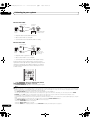
Connecting the speakers
Each speaker connection on the receiver comprises a
positive (+) and negative (–) terminal. Make sure to
match these up with the terminals on the speakers
themselves.
CAUTION
• These speaker terminals carry HAZARDOUS LIVE
voltage. To prevent the risk of electric shock when
connecting or disconnecting the speaker cables,
disconnect the power cord before touching any
uninsulated parts.
• Make sure that all the bare speaker wire is twisted
together and inserted fully into the speaker terminal.
If any of the bare speaker wire touches the back panel
it may cause the power to cut off as a safety measure.
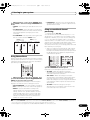
Bare wire connections
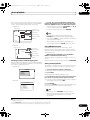
1
Twist exposed wire strands together. (fig. A)
2
Loosen terminal and insert exposed wire. (fig. B)
3
Tighten terminal. (fig. C)
fig. A
fig. B
fig. C
10 mm (3/8 in.)
Banana plug connections
If you want to use speaker cables terminated with banana
plugs, screw the speaker terminal fully shut, then plug
the banana plug into the end of the speaker terminal.
Important
• Please refer to the manual that came with your
speakers for details on how to connect the other end
of the speaker cables to your speakers.
• Use an RCA cable to connect the subwoofer. It is not
possible to connect using speaker cables.
CAUTION
• Make sure that all speakers are securely installed.
This not only improves sound quality, but also
reduces the risk of damage or injury resulting from
speakers being knocked over or falling in the event of
external shocks such as earthquakes.
19
En
VSX-23TXH_CUXJ.book
03
20 ページ
2009年5月8日 金曜日 午前10時45分
Connecting your equipment
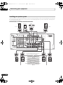
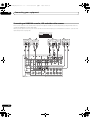
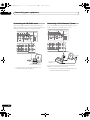
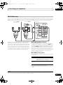
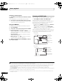
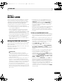
Installing your speaker system
At the very least, front left and right speakers only are necessary. Note that your main surround speakers should always
be connected as a pair, but you can connect just one surround back speaker if you like (it must be connected to the
left surround back terminal).
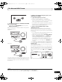
Standard 5.1/6.1/7.1-channel surround connections
Center
Subwoofer
Front left
Front right
LINE LEVEL
INPUT
HDMI
IN 1
BD IN
IN 2
OUT 1 (KURO
LINK)
IN 3
ASSIGNABLE
1 3
COAXIAL
OUT 2
ASSIGNABLE
ASSIGNABLE
IN 1
IN 2
IN 1
OPTICAL
OUT
IN 3
IN 2
SIRIUS
XM
(DVD)
ASSIGNABLE
IN 1
(DVD)
Y
(CD)
(TV/SAT)
IN 2 L
(DVR)
Y
FRONT
(DVR)
(VIDEO)
CENTER
SURROUND
FRONT
AUDIO
CENTER
PB
PB
PR
Y
MONITOR
OUT
FM UNMAL
75 ޓޓ
L
(Single)
R
PR
AC IN
ANTENNA
IN
IN
COMPONENT
VIDEO
R
AM LOOP
ZONE2
ZONE3
DVD
TV/SAT
VIDEO
OUT
OUT
MONITOR
OUT
IN
IN
IN
DVR
OUT
CD
IN
CD-R/TAPE
IN
OUT
SUBWOOFER SURROUND SURROUND
BACK
SUBWOOFER
IN
MULTI CH IN
PRE OUT
VIDEO
SPEAKERS
A
PB
R
FRONT
L
CENTER
R
SURROUND
L
R
SURROUND BACK /
B
L
(Single)
S-VIDEO
PR
12 V TRIGGER
CONTROL
RS-232C
IN
OUT
IR
IN 1
IN 2 OUT
(OUTPUT 12 V
TOTAL 50 mA MAX)
1
2
VSX-23TXH
The surround back terminals can also be
used for the Speaker B and ZONE 2.
7.1 ch surround setting
Surround back right
Surround back left
6.1 ch surround setting
Surround back
No connect
Surround left
Speaker B setting
Speaker B - Right
Speaker B - Left
ZONE 2 setting
ZONE 2 - Left
20
En
ZONE 2 - Right
Surround right
VSX-23TXH_CUXJ.book
21 ページ
2009年5月8日 金曜日 午前10時45分
Connecting your equipment
03
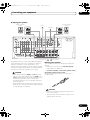
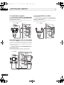
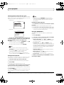
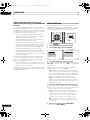
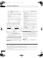
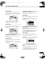
Bi-amping your speakers
Bi-amp compatible
speaker
Bi-amp compatible
speaker
Center
Subwoofer
High
High
Low
Low
Front left
HDMI
Front right
IN 1
BD IN
IN 2
OUT 1 (KURO
LINK)
IN 3
ASSIGNABLE
1 3
COAXIAL
OUT 2
ASSIGNABLE
ASSIGNABLE
IN 1
IN 2
IN 1
IN 2
OPTICAL
OUT
IN 3
SIRIUS
XM
(DVD)
ASSIGNABLE
IN 1
(DVD)
Y
(CD)
(TV/SAT)
IN 2 L
(DVR)
Y
FRONT
(DVR)
(VIDEO)
CENTER
SURROUND
FRONT
AUDIO
CENTER
PB
PB
PR
Y
MONITOR
OUT
FM UNMAL
75 ޓޓ
L
(Single)
R
PR
AC IN
ANTENNA
IN
IN
COMPONENT
VIDEO
R
AM LOOP
ZONE2
ZONE3
DVD
TV/SAT
VIDEO
OUT
OUT
MONITOR
OUT
IN
IN
IN
DVR
OUT
CD
IN
CD-R/TAPE
IN
OUT
SUBWOOFER SURROUND SURROUND
BACK
SUBWOOFER
IN
MULTI CH IN
PRE OUT
VIDEO
SPEAKERS
A
PB
R
FRONT
L
CENTER
R
SURROUND
L
R
SURROUND BACK /
B
L
(Single)
S-VIDEO
PR
12 V TRIGGER
CONTROL
RS-232C
VSX-23TXH
IN
OUT
IR
IN 1
IN 2 OUT
(OUTPUT 12 V
TOTAL 50 mA MAX)
1
2
Surround right
Bi-amping is when you connect the high frequency driver
and low frequency driver of your speakers to different
amplifiers for better crossover performance. Your
speakers must be bi-ampable to do this (having separate
terminals for high and low) and the sound improvement
will depend on the kind of speakers you’re using.
CAUTION
• Most speakers with both High and Low terminals
have two metal plates that connect the High to the
Low terminals. These must be removed when you are
bi-amping the speakers or you could severely
damage the amplifier. See your speaker manual for
more information.
Surround left
Bi-wiring your speakers
Your speakers can also be bi-wired if they support biamping.
• With these connections, the Surr Back System
setting makes no difference.
• To bi-wire a speaker, connect two speaker cords to
the speaker terminal on the receiver.
Using a banana plug for the second connection is
recommended.
• If your speakers have a removable crossover network,
make sure you do not remove it for bi-amping. Doing
so may damage your speakers.
CAUTION
• Don’t connect different speakers from the same
terminal in this way.
• When bi-wiring as well, heed the cautions for biamping shown at the left.
21
En
VSX-23TXH_CUXJ.book
03
22 ページ
2009年5月8日 金曜日 午前10時45分
Connecting your equipment
Selecting the Surr Back system
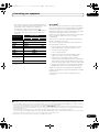
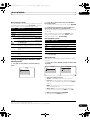
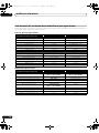
About the audio connection
The surround back terminals can be used for bi-amping,
Speaker B and ZONE 2 connections, in addition to for the
surround back speakers. Make this setting according to
the application.
There are several types of audio input and output
terminals on this receiver. The receiver selects the first
available signal in the following order when you choose
AUTO as the input signal:
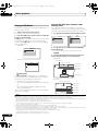
ZONE 2 setup
1 Connect a pair of speakers to the surround back
speaker terminals.
See Standard 5.1/6.1/7.1-channel surround connections
on page 20.
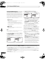
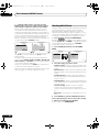
2 Select ‘ZONE 2’ from the Surr Back System menu.
See Surround back speaker setting on page 91 to do this.
Types of cables and
terminals
Sound signal priority
With these connections you can simultaneously enjoy
5.1-channel surround sound in the main zone with stereo
playback on another component in ZONE 2.
HDMI
Digital (Coaxial)
Transferable audio
signals
HD audio
Conventional digital audio
Digital (Optical)
Speaker B setup
You can listen to stereo playback in another room.
1 Connect a pair of speakers to the surround back
speaker terminals.
See Standard 5.1/6.1/7.1-channel surround connections
on page 20.
2 Select ‘Speaker B’ from the Surr Back System
menu.
See Surround back speaker setting on page 91 to do this.
Bi-Amping setup
Bi-amping connection of the front speakers for high
sound quality with 5.1-channel surround sound.
1 Connect Bi-amp compatible speakers to the front
and surround back speaker terminals.
See Bi-amping your speakers on page 21.
2 Select ‘Front Bi-Amp’ from the Surr Back System
menu.
See Surround back speaker setting on page 91 to do this.
22
En
RCA (Analog)
(White/Red)
Conventional analog audio
• With an HDMI cable, video and audio signals can be
transferred in high quality over a single cable.
CAUTION
• When connecting optical cables, be careful when
inserting the plug not to damage the shutter
protecting the optical socket.
• When storing optical cable, coil loosely. The cable
may be damaged if bent around sharp corners.
VSX-23TXH_CUXJ.book
23 ページ
2009年5月8日 金曜日 午前10時45分
Connecting your equipment
03
About the video converter
The video converter ensures that all video sources are output through all of the MONITOR OUT jacks. The only
exception is HDMI: since this resolution cannot be downsampled, you must connect your monitor/TV to the receiver’s
HDMI video outputs when connecting this video source.1
If several video components are assigned to the same input function (see The Input Setup menu on page 43), the
converter gives priority to HDMI, component, S-Video, then composite (in that order).
This receiver
Source device
High picture quality
Terminal for
connection with
source device
TV monitor
Terminal for
connection with TV
monitor
HDMI OUT
HDMI IN
Y
PB
Types of cables
PR
Y
PB
PR
COMPONENT
VIDEO IN
COMPONENT VIDEO
MONITOR OUT
S-VIDEO IN
S-VIDEO
MONITOR OUT
VIDEO IN
VIDEO
MONITOR OUT
Video signals can be output
• For optimal video performance, THX recommends
switching Digital Video Conversion (in Setting the
Video options on page 68) OFF.
This product incorporates copyright protection
technology that is protected by method claims of certain
U.S. patents and other intellectual property rights owned
by Macrovision Corporation and other rights owners.
Use of this copyright protection technology must be
authorized by Macrovision Corporation, and is intended
for home and other limited viewing uses only unless
otherwise authorized by Macrovision Corporation.
Reverse engineering or disassembly is prohibited.
Note
1 • If the video signal does not appear on your TV or flat panel TV, try adjusting the resolution settings on your component or display. Note that
some components (such as video game units) have resolutions that may not be converted. In this case, try switching Digital Video Conversion
(in Setting the Video options on page 68) OFF.
• The signal input resolutions that can be converted from the component video input for the HDMI output are 480i/576i, 480p/576p, 720p and
1080i. 1080p signal cannot be converted.
• Only signals with an input resolution of 480i/576i can be converted from the component video input for the composite and S-Video MONITOR
OUT.
23
En
VSX-23TXH_CUXJ.book
03
24 ページ
2009年5月8日 金曜日 午前10時45分
Connecting your equipment
Connecting your TV and playback components
Connecting using HDMI
If you have an HDMI or DVI (with HDCP) equipped component (Blu-ray disc player, etc.), you can connect it to this
receiver using a commercially available HDMI cable.
If the TV and playback components support the Pioneer KURO LINK feature, the convenient KURO LINK functions can
be used (see KURO LINK on page 63).
HDMI/DVI-compatible
Blu-ray disc player
Other HDMI/DVIequipped component
HDMI/DVI-compatible monitor
or flat panel TV
HDMI OUT
HDMI OUT
Select one
HDMI IN
AUDIO OUT
DIGITAL OUT
COAXIAL OPTICAL
R ANALOG L
This connection is
required in order to
listen to the sound of
the TV over the receiver.
HDMI
IN 1
BD IN
IN 2
OUT 1 (KURO
LINK)
IN 3
ASSIGNABLE
1 3
COAXIAL
OUT 2
ASSIGNABLE
ASSIGNABLE
IN 1
IN 2
IN 1
OUT
IN 3
IN 2
OPTICAL
XM
IN
COMPONENT
VIDEO
(DVD)
ASSIGNABLE
IN 1
(DVD)
Y
(CD)
(TV/SAT)
IN 2 L
(DVR)
Y
FRONT
(DVR)
(VIDEO)
CENTER
SURROUND
FRONT
CENTER
R
PB
PB
PR
PR
Y
MONITOR
OUT
ZONE2
ZONE3
DVD
TV/SAT
VIDEO
OUT
OUT
MONITOR
OUT
IN
IN
IN
DVR
OUT
CD
IN
CD-R/TAPE
IN
OUT
SUBWOOFER S
SUBWOOFER
IN
MULTI CH IN
PRE
VIDEO
SPEAKERS
A
PB
R
FRONT
L
CENTER
R
SURROUND
L
S-VIDEO
PR
12 V TRIGGER
CONTROL
RS-232C
IN
OUT
IR
IN 1
IN 2 OUT
(OUTPUT 12 V
TOTAL 50 mA MAX)
1
2
VSX-23TXH
• When connecting a Blu-ray disc player, connect the
player to the receiver’s BD IN terminal.
• VSX-23TXH only: When connecting to an HDMI/DVIcompatible monitor or a flat panel TV using the HDMI
OUT 2 terminal, switch the HDMI output setting to
HDMI OUT 2 or HDMI OUT ALL. See Switching the
HDMI output on page 71.
• The HDMI indicator lights on the front panel when an
HDMI-equipped component is connected.
• For input components, connections other than HDMI
connections are also possible (see Connecting your
DVD player with no HDMI output on page 25).
24
En
• If your Blu-ray disc player offers multi-channel analog
audio outputs, see Connecting the multichannel
analog inputs on page 29.
• The sound of the TV cannot be heard over the receiver
if the TV is connected using an HDMI cable.
If you want to listen to the sound of the TV over the
receiver, connect the receiver and TV with audio
cables. When making digital connections with a
coaxial cable at this time, the digital input setting
must be made (see The Input Setup menu on
page 43).
VSX-23TXH_CUXJ.book
25 ページ
2009年5月8日 金曜日 午前10時45分
Connecting your equipment
03
Connecting your DVD player with no HDMI output
This diagram shows connections of a TV (with HDMI input) and DVD player (or other playback component with no
HDMI output) to the receiver.
DVD player, etc.
HDMI/DVI-compatible
monitor or flat panel TV
AUDIO OUT
DIGITAL OUT
COAXIAL OPTICAL
R ANALOG L
HDMI
Select one
Select one
HDMI IN
IN 1
BD IN
IN 2
OUT 1 (KURO
LINK)
IN 3
ASSIGNABLE
1 3
COAXIAL
OUT 2
IN 2
PR
ASSIGNABLE
ASSIGNABLE
IN 1
COMPONENT VIDEO OUT
IN 1
OUT
IN 3
IN 2
PB
Y
VIDEO OUT
VIDEO S-VIDEO
OPTICAL
XM
IN
COMPONENT
VIDEO
(DVD)
ASSIGNABLE
IN 1
(DVD)
Y
(CD)
(TV/SAT)
IN 2 L
(DVR)
Y
FRONT
(DVR)
(VIDEO)
CENTER
SURROUND
FRONT
CENTER
R
PB
PB
PR
PR
Y
MONITOR
OUT
ZONE2
ZONE3
DVD
TV/SAT
VIDEO
OUT
OUT
MONITOR
OUT
IN
IN
IN
DVR
OUT
CD
IN
CD-R/TAPE
IN
OUT
SUBWOOFER S
SUBWOOFER
IN
MULTI CH IN
PRE
VIDEO
SPEAKERS
A
PB
R
FRONT
L
CENTER
R
SURROUND
L
S-VIDEO
PR
12 V TRIGGER
CONTROL
RS-232C
IN
OUT
IR
IN 1
IN 2 OUT
(OUTPUT 12 V
TOTAL 50 mA MAX)
1
2
VSX-23TXH
• If you want to listen to the sound of the TV over the
receiver, connect the receiver and TV with audio
cables.
• Component video should give superior picture quality
when compared to composite or S-Video. You can also
take advantage of progressive scan video (if your
source and TV are both compatible), which delivers a
very stable, flicker-free picture. See the manuals that
came with your TV and source component to check
whether they are compatible with progressive-scan
video.
• If your DVD player offers multi-channel analog audio
outputs, see Connecting the multichannel analog inputs
on page 29.
25
En
VSX-23TXH_CUXJ.book
03
26 ページ
2009年5月8日 金曜日 午前10時45分
Connecting your equipment
Connecting your TV with no HDMI input
This diagram shows connections of a TV (with no HDMI input) and DVD player (or other playback component) to the
receiver.
• With these connections, the picture is not output to the TV even if the DVD player is connected with an HDMI cable.
Connect the DVD player’s video signals using a composite, S-Video or component cord.
DVD player, etc.
TV
Select one
VIDEO IN
S-VIDEO VIDEO
Select one
HDMI OUT
COMPONENT VIDEO IN
PR
PB
Select one
AUDIO OUT
DIGITAL OUT
COAXIAL OPTICAL
R ANALOG L
Y
HDMI
IN 1
BD IN
IN 2
OUT 1 (KURO
LINK)
IN 3
ASSIGNABLE
1 3
COAXIAL
OUT 2
IN 2
PR
ASSIGNABLE
ASSIGNABLE
IN 1
COMPONENT VIDEO OUT
IN 1
OUT
IN 3
IN 2
PB
Y
VIDEO OUT
VIDEO S-VIDEO
OPTICAL
XM
IN
COMPONENT
VIDEO
(DVD)
ASSIGNABLE
IN 1
(DVD)
Y
(CD)
(TV/SAT)
IN 2 L
(DVR)
Y
FRONT
(DVR)
(VIDEO)
CENTER
SURROUND
FRONT
CENTER
R
PB
PB
PR
PR
Y
MONITOR
OUT
ZONE2
ZONE3
DVD
TV/SAT
VIDEO
OUT
OUT
MONITOR
OUT
IN
IN
IN
DVR
OUT
CD
IN
CD-R/TAPE
IN
OUT
SUBWOOFER S
SUBWOOFER
IN
MULTI CH IN
PRE
VIDEO
SPEAKERS
A
PB
R
FRONT
L
CENTER
R
SURROUND
L
S-VIDEO
PR
12 V TRIGGER
CONTROL
RS-232C
IN
OUT
IR
IN 1
IN 2 OUT
(OUTPUT 12 V
TOTAL 50 mA MAX)
1
2
VSX-23TXH
• Connect using an HDMI cable to listen to HD audio
on the receiver. Do not use an HDMI cable to input
video signals.
Depending on the video component, it may not be
possible to output signals connected by HDMI and
other methods simultaneously, and it may be
necessary to make output settings. Please refer to the
operating instructions supplied with your component
for more information.
26
En
• Component video should give superior picture quality
when compared to composite or S-Video. You can also
take advantage of progressive scan video (if your
source and TV are both compatible), which delivers a
very stable, flicker-free picture. See the manuals that
came with your TV and source component to check
whether they are compatible with progressive-scan
video.
• If your DVD player has multichannel analog outputs,
you can connect these instead. See also Connecting
the multichannel analog inputs on page 29.
VSX-23TXH_CUXJ.book
27 ページ
2009年5月8日 金曜日 午前10時45分
Connecting your equipment
03
• The input functions below are assigned by default to
the receiver’s different input terminals. Refer to The
Input Setup menu on page 43 to change the
assignments if other connections are used.
For example, the BD terminal is fixed to BD input; no
other audio and video signals can be input to this
terminal.
Input function
DVD
Input Terminals
Digital
IN 1
DVR
OPT-2
OPT-3
IN 2
HDMI 1
(HDMI-1)
HDMI 2
(HDMI-2)
HDMI 3
(HDMI-3)
HDMI 4a
(HDMI-4)
(front panel)
a. VSX-23TXH only
b. VSX-21TXH only
COAX-2
The HDMI connection transfers uncompressed digital
video, as well as almost every kind of digital audio that the
connected component is compatible with, including
DVD-Video, DVD-Audio, SACD, Dolby Digital Plus, Dolby
TrueHD, DTS-HD Master Audio (see below for
limitations), Video CD/Super VCD and CD. See About the
video converter on page 23 for more on HDMI
compatibility.
This receiver incorporates High-Definition Multimedia
Interface (HDMI™) technology.
This receiver supports the functions described below
through HDMI connections.
OPT-1
VIDEOa/VIDEO 1b
CD
Component
(BD)
BD
TV/SAT
HDMI
COAX-1
About HDMI1
• Digital transfer of uncompressed video (contents
protected by HDCP (1080p/24, 1080p/60, etc.))
• Deep Color signal transfer2
• x.v.Color signal transfer2
• Input of multi-channel linear PCM digital audio
signals (192 kHz or less) for up to 8 channels
• Input of the following digital audio formats:
– Dolby Digital, Dolby Digital Plus, DTS, High bitrate
audio (Dolby TrueHD, DTS-HD Master Audio), DVDAudio, CD, SACD (DSD signal), Video CD, Super VCD
• Synchronized operation with components using the
KURO LINK function (see KURO LINK on page 63)
HDMI, the HDMI logo and High-Definition Multimedia
Interface are trademarks or registered trademarks of HDMI
Licensing, LLC.
“x.v.Color” and x.v.Color logo are trademarks of Sony
Corporation.
Note
1 • An HDMI connection can only be made with DVI-equipped components compatible with both DVI and High Bandwidth Digital Content
Protection (HDCP). If you choose to connect to a DVI connector, you will need a separate adaptor (DVIHDMI) to do so. A DVI connection,
however, does not support audio signals. Consult your local audio dealer for more information.
• If you connect a component that is not compatible with HDCP, an HDCP ERROR message is displayed on the front panel display. Some
components that are compatible with HDCP still cause this message to be displayed, but so long as there is no problem with displaying video
this is not a malfunction.
• Depending on the component you have connected, using a DVI connection may result in unreliable signal transfers.
• This receiver supports SACD, Dolby Digital Plus, Dolby TrueHD and DTS-HD Master Audio. To take advantage of these formats, however, make
sure that the component connected to this receiver also supports the corresponding format.
2 Signal transfer is only possible when connected to a compatible component.
27
En
VSX-23TXH_CUXJ.book
03
28 ページ
2009年5月8日 金曜日 午前10時45分
Connecting your equipment
Connecting an HDD/DVD recorder, VCR and other video sources
This receiver has two sets of audio/video inputs and outputs suitable for connecting analog or digital video devices,
including HDD/DVD recorders and VCRs.
When you set up the receiver you’ll need to tell the receiver which input you connected the recorder to (see also The
Input Setup menu on page 43).
HDD/DVD recorder, VCR, etc.
Select one
HDMI
Select one
Select one
VIDEO IN
S-VIDEO
VIDEO
AUDIO IN
IN 1
BD IN
IN 2
OUT 1 (KURO
LINK)
IN 3
ASSIGNABLE
1 3
COAXIAL
OUT 2
IN 2
R ANALOG L
ASSIGNABLE
ASSIGNABLE
IN 1
IN 1
VIDEO OUT
VIDEO S-VIDEO
AUDIO OUT
DIGITAL OUT
COAXIAL OPTICAL
R ANALOG L
OUT
IN 3
IN 2
OPTICAL
XM
IN
COMPONENT
VIDEO
(DVD)
ASSIGNABLE
IN 1
(DVD)
Y
(CD)
(TV/SAT)
IN 2 L
(DVR)
Y
FRONT
(DVR)
(VIDEO)
CENTER
SURROUND
FRONT
CENTER
R
PB
PB
PR
PR
Y
MONITOR
OUT
ZONE2
ZONE3
DVD
TV/SAT
VIDEO
OUT
OUT
MONITOR
OUT
IN
IN
IN
DVR
OUT
CD
IN
CD-R/TAPE
IN
OUT
MULTI CH IN
SPEAKERS
A
S-VIDEO
PR
12 V TRIGGER
CONTROL
VSX-23TXH
28
En
PRE
VIDEO
PB
RS-232C
SUBWOOFER S
SUBWOOFER
IN
IN
OUT
IR
IN 1
IN 2 OUT
(OUTPUT 12 V
TOTAL 50 mA MAX)
1
2
R
FRONT
L
CENTER
R
SURROUND
L
VSX-23TXH_CUXJ.book
29 ページ
2009年5月8日 金曜日 午前10時45分
Connecting your equipment
03
Connecting a satellite/cable receiver or
other set-top box
Connecting the multichannel analog
inputs
Satellite and cable receivers, and terrestrial digital TV
tuners are all examples of so-called ‘set-top boxes’.
For DVD Audio and SACD playback, your DVD player may
have 5.1 channel analog outputs. Make sure that the
player is set to output multichannel analog audio.
When you set up the receiver you’ll need to tell the
receiver which input you connected the set-top box to
(see The Input Setup menu on page 43).
DVD player, etc.
STB
Select one
R
Select one
VIDEO OUT
S-VIDEO
VIDEO
AUDIO OUT
FRONT
OUTPUT
CENTER
OUTPUT
L
SURROUND
OUTPUT
R
L
SUBWOOFER
OUTPUT
DIGITAL OUT
COAXIAL OPTICAL
R ANALOG L
OUT 1 (KURO
LINK)
COAXIAL
OUT 2
ASSIGNABLE
ASSIGNABLE
IN 1
IN 2
IN 1
OUT
IN 3
IN 2
OPTICAL
XM
IN
(DVD)
(CD)
(TV/SAT)
FRONT
N1
IN 2
OUT 1 (KURO
LINK)
IN 3
COAXIAL
OUT 2
ASSIGNABLE
ASSIGNABLE
IN 1
IN 2
IN 1
OUT
IN 3
IN 2
(DVR)
(VIDEO)
CENTER
SURROUND
FRONT
CENTER
OPTICAL
XM
IN
(DVD)
(CD)
(TV/SAT)
FRONT
(DVR)
(VIDEO)
CENTER
SURROUND
FRONT
CENTER
O
DVR
OUT
CD
IN
CD-R/TAPE
IN
OUT
SUBWOOFER
SUBWOOFER
IN
MULTI CH IN
2
ZONE3
DVD
TV/SAT
VIDEO
OUT
MONITOR
OUT
IN
IN
IN
DVR
OUT
CD
IN
CD-R/TAPE
IN
OUT
SPEAKERS
SUBWOOFER
SUBWOOFER
A
IN
MULTI CH IN
R
FRONT
L
CENTER
R
PRE
SURROUND
L
PRE
O
12 V TRIGGER
SPEAKERS
A
R
FRONT
L
CENTER
R
SURROUND
L
T
(OUTPUT 12 V
TOTAL 50 mA MAX)
1
2
S-VIDEO
12 V TRIGGER
ONTROL
N
OUT
IR
IN 1
VSX-23TXH
IN 2 OUT
(OUTPUT 12 V
TOTAL 50 mA MAX)
1
2
VSX-23TXH
• If your player has 7.1-channel analog outputs, the
player’s surround back output terminals are not
used. Please refer to the operating instructions
supplied with your component for more information.
Connecting other audio components
This receiver has both digital and analog inputs, allowing
you to connect audio components for playback.
This receiver features five stereo audio-only inputs. One
of these inputs have corresponding outputs for use with
audio recorders.
Most digital components also have analog connections.
29
En
VSX-23TXH_CUXJ.book
03
30 ページ
2009年5月8日 金曜日 午前10時45分
Connecting your equipment
When you set up the receiver you’ll need to tell the
receiver which input you connected the component to
(see also The Input Setup menu on page 43).
CD-R, MD, DAT, etc.
Select one
DIGITAL IN
OPTICAL
Connecting additional amplifiers
This receiver has more than enough power for any home
use, but it’s possible to add additional amplifiers to every
channel of your system using the pre-outs. Make the
connections shown below to add amplifiers to power
your speakers.
Select one
AUDIO IN
ANALOG
INPUT
AUDIO OUT
DIGITAL OUT
COAXIAL OPTICAL
R ANALOG L
R ANALOG L
L
R
Front channel
amplifier
ANALOG
INPUT
Center channel
amplifier (mono)
ANALOG
INPUT
L
OUT 1 (KURO
LINK)
COAXIAL
OUT 2
ASSIGNABLE
ASSIGNABLE
IN 1
IN 2
IN 1
OUT
IN 3
IN 2
OPTICAL
R
XM
IN
(DVD)
(CD)
(TV/SAT)
FRONT
(DVR)
(VIDEO)
CENTER
SURROUND
OUT
FRONT
OPTICAL
SIRIUS
XM
CENTER
IN
IN
ANALOG
INPUT
EO)
ND
FRONT
AUDIO
CENTER
L
L
(Single)
O
DVR
OUT
CD
IN
R
CD-R/TAPE
IN
OUT
SUBWOOFER S
SUBWOOFER
R
IN
MULTI CH IN
PRE
Surround channel
amplifier
SUBWOOFER SURROUND SURROUND
BACK
Surround back
channel amplifier
PRE OUT
SPEAKERS
A
R
FRONT
L
CENTER
R
SURROUND
12 V TRIGGER
T
ANALOG
INPUT
L
(OUTPUT 12 V
TOTAL 50 mA MAX)
1
2
SURROUND
L
R
SURROUND BACK /
B
Powered
subwoofer
VSX-23TXH
• If your turntable has line-level outputs (i.e., it has a
built-in phono pre-amp), connect it to the CD inputs
instead.
• You can use the additional amplifier on the surround
back channel pre-outs for a single speaker as well. In
this case plug the amplifier into the left (L (Single))
terminal only.
• If you’re connecting a recorder, connect the analog
audio outputs to the analog audio inputs on the
recorder.
• The sound from the surround back terminals will
depend on how you have configured the Surround
back speaker setting on page 91.
About the WMA9 Pro decoder
This unit has an on-board Windows Media™ Audio 9
Professional1 (WMA9 Pro) decoder, so it is possible to
playback WMA9 Pro-encoded audio using HDMI, coaxial
or optical digital connection when connected to a WMA9
Pro-compatible player. However, the connected DVD
player, set-top box, etc. must be able to output WMA9 Pro
format audio signals through a coaxial or optical digital
output.
• To hear sound only from the pre-outs, switch the
speaker system to OFF, or simply disconnect any
speakers that are connected directly to the receiver.
If you’re not using a subwoofer, change the front speaker
setting (see Speaker Setting on page 91) to LARGE.
Note
1 • Windows Media and the Windows logo are trademarks or registered trademarks of Microsoft Corporation in the United States and/or other
countries.
• With WMA9 Pro, sound problems may occur depending on your computer system. Note that WMA9 Pro 96 kHz sources will be
downsampled to 48 kHz.
30
En
VSX-23TXH_CUXJ.book
31 ページ
2009年5月8日 金曜日 午前10時45分
Connecting your equipment
03
Connecting external antennas
Connecting AM/FM antennas
Connect the AM loop antenna and the FM wire antenna
as shown below. To improve reception and sound quality,
connect external antennas (see Connecting external
antennas below).
1
To improve FM reception connect an external FM
antenna to the FM UNBAL 75 Ω.
75 Ω coaxial cable
2
ANTENNA
FM UNBAL
75
3
ANTENNA
FM UNBAL
75
5
AM LOOP
AM LOOP
4
fig. a
fig. b
fig. c
To improve AM reception, connect a 5 m to 6 m (16 ft. to
20 ft.) length of vinyl-coated wire to the AM LOOP
terminals without disconnecting the supplied AM loop
antenna.
For the best possible reception, suspend horizontally
outdoors.
Outdoor
antenna
1 Pull off the protective shields of both AM antenna
wires.
2 Push open the tabs, then insert one wire fully into
each terminal, then release the tabs to secure the AM
antenna wires.
3 Fix the AM loop antenna to the attached stand.
To fix the stand to the antenna, bend in the direction
indicated by the arrow (fig. a) then clip the loop onto the
stand (fig. b).
ANTENNA
Indoor antenna
(vinyl-coated wire)
FM UNBAL
75
AM LOOP
5 m to 6 m
(16 ft. to 20 ft.)
• If you plan to mount the AM antenna to a wall or other
surface, secure the stand with screws (fig. c) before
clipping the loop to the stand. Make sure the
reception is clear.
4 Place the AM antenna on a flat surface and in a
direction giving the best reception.
5 Connect the FM wire antenna in the same way as
the AM loop antenna.
For best results, extend the FM antenna fully and fix to a
wall or door frame. Don’t drape loosely or leave coiled up.
31
En
VSX-23TXH_CUXJ.book
03
32 ページ
2009年5月8日 金曜日 午前10時45分
Connecting your equipment
Connecting an XM Radio tuner
Connecting a SiriusConnect™ tuner
After purchasing an XM Mini-Tuner and Home Dock
(both sold separately), you will also need to activate the
XM Radio service to begin receiving broadcasts.
To receive SIRIUS Satellite Radio broadcasts, you will
need to activate your SiriusConnect™ tuner.
ASSIGNABLE
BLE
2
ASSIGNABLE
BLE
2
IN 1
OUT
IN 3
IN 2
OPTICAL
(TV/SAT)
XM
(DVR)
(VIDEO)
CENTER
SURROUND
OUT
IN 3
IN 2
OPTICAL
SIRIUS
XM
ANTENNA
IN
(TV/SAT)
FRONT
(DVR)
(VIDEO)
CENTER
SURROUND
FRONT
ANTENNA
IN
IN
SIRIUS
IN
FRONT
IN 1
AUDIO
CENTER
FM UNMAL
75 ޓޓ
L
(Single)
FRONT
AUDIO
CENTER
FM UNMAL
75 ޓޓ
L
(Single)
R
AM LOOP
R
AM LOOP
MULTI CH IN
SUBWOOFER SURROUND SURROUND
BACK
SUBWOOFER
MULTI CH IN
CENTER
R
PRE OUT
PRE OUT
L
L
SUBWOOFER SURROUND SURROUND
BACK
SUBWOOFER
SURROUND
L
R
SURROUND BACK /
B
CENTER
R
SURROUND
L
R
SURROUND BACK /
B
L
(Single)
L
(Single)
Antenna
SIRIUS
H
AC adapter
SIR
IUS
SATELLiTE
RADiO
SATELLiTE RADiO
XM Mini-Tuner and
Home Dock with antenna
• For instructions on playing the XM Radio, see
Listening to XM Radio on page 52.
32
En
H
SiriusConnect™
HOME tuner
You will also need to connect the antenna and AC
adapter to the SiriusConnect™ tuner.
• For instructions on playing the SIRIUS Radio, see
Listening to SIRIUS Radio on page 54.
VSX-23TXH_CUXJ.book
33 ページ
2009年5月8日 金曜日 午前10時45分
Connecting your equipment
03
MULTI-ZONE setup
This receiver can power up to two (VSX-21TXH)/three (VSX-23TXH) independent systems in separate rooms after you have
made the proper MULTI-ZONE connections. An example MULTI-ZONE setup is shown below, but the number of MULTIZONE connections (and the way you choose to connect them) depends on how you want to set up your system.
Sub zone (ZONE 3)
(VSX-23TXH only)
Main zone
Sub zone (ZONE 2)
HDMI
IN 1
BD IN
IN 2
IN 3
ASSIGNABLE
1 3
COMPONENT
VIDEO
VIDEO IN
ASSIGNABLE
IN 1
(DVD)
Y
IN 2 L
(DVR)
Y
R
PB
PB
PR
PR
Y
MONITOR
OUT
ZONE2
ZONE3
DVD
TV/SAT
OUT
OUT
MONITOR
OUT
IN
IN
VIDEO
PB
AUDIO IN
R
AUDIO IN
L
R
S-VIDEO
L
PR
CONTROL
RS-232C
IN
OUT
IR
IN 1
IN 2
VSX-23TXH
Different sources can be playing in two (VSX-21TXH)/three
(VSX-23TXH) zones at the same time or, depending on
your needs, the same source can also be used. The main
and sub zone(s) have independent power (the main zone
power can be off while one (or both) of the sub zone(s) is
on) and the sub zone(s) can be controlled by the remote
or front panel controls. However, you may need to specify
the volume settings in ZONE Audio Setup on page 95.
Making MULTI-ZONE connections
It is possible to make these connections if you have a
separate TV and speakers for your primary (ZONE 2) sub
zone (and a separate amplifier1 (and speakers) for your
secondary (ZONE 3) sub zone (VSX-23TXH only)). You will
also need a separate amplifier if you are not using the
MULTI-ZONE setup using speaker terminals (ZONE 2) on
page 34 for your primary sub zone. There are two primary
sub zone setups possible with this system. Choose
whichever works best for you.
MULTI-ZONE listening options
The following table shows the signals that can be output
to sub zone(s):
Sub zone
Input functions available
ZONE 2
Analog audio signals (AUDIO ZONE 2 OUT).a
With video signals,b the composite video (VIDEO
ZONE 2 OUT) signals can be output.
ZONE 3
(VSX-23TXH
only)
Analog audio signals (AUDIO ZONE 3 OUT).a,c
a.Any analog signal. (This does not apply for the MULTI CH IN input.)
b.JPEG files cannot be played with the USB input.
c.iPod/USB, XM or SIRIUS Radio function cannot be selected for
ZONE 3.
Note
1 You can’t use sound controls (such as the tone controls or Midnight listening) or any surround modes with a separate amplifier in the sub
zone. You can, however, use the features available with your sub zone amplifier.
33
En
VSX-23TXH_CUXJ.book
03
34 ページ
2009年5月8日 金曜日 午前10時45分
Connecting your equipment
Basic MULTI-ZONE setup (ZONE 2)
Secondary MULTI-ZONE setup (ZONE 3)
• Connect a separate amplifier to the AUDIO ZONE 2
OUT jacks and a TV monitor to the VIDEO ZONE 2 OUT
jack, both on this receiver.
You should have a pair of speakers attached to the sub
zone amplifier as shown below.
Main zone
Sub zone (ZONE 2)
• Connect a separate amplifier to the AUDIO ZONE 3
OUT jacks on this receiver.
You should have a pair of speakers attached to the sub
zone amplifier as shown below.
Sub zone (ZONE 3)
HDMI
VIDEO IN
(VSX-23TXH only)
IN 1
BD IN
Main zone
HDMI
ASSIGNABLE
1 3
ASSIGNABLE
1 3
COMPONENT
VIDEO
COMPONENT
VIDEO
ASSIGNABLE
IN 1
(DVD)
Y
ASSIGNABLE
IN 1
(DVD)
Y
IN 2 L
(DVR)
Y
IN 1
BD IN
IN 2 L
(DVR)
Y
R
PB
R
PB
PR
PR
Y
MONITOR
OUT
PB
ZONE2
ZONE3
OUT
OUT
MONITOR
OUT
VIDEO
PB
PR
Y
MONITOR
OUT
PR
R
IN
RS-232C
OUT
You must select ZONE 2 in Surround back speaker setting
on page 91 to use this setup. Note that the sound in the
sub zone will be temporarily interrupted when controlling
the main zone (for example, changing the input function
or starting playback).
• Connect a TV monitor to the VIDEO ZONE 2 OUT
jacks on this receiver.
You should have a pair of speakers attached to the
surround back speaker terminals as shown below.
Main zone
1
INOPTICAL
BD IN
ASSIGNABLE
1 3
IN
OUT
ANTE
COMPONENT
VIDEO
IN 2
(DVR) L
Y
Y
VIDEO IN
L
(Single)
PB
PB
PR
Y
MONITOR
OUT
R
ZONE2
SUBWOOFER
SURROUND
ZONE3 SURROUND
DV
BACK
OUT
I
OUT
MONITOR
PRE OUT
OUT
VIDEO
D
SURROUND BACK /
L
PB
L
R
S-VIDEO
PR
CONTROL
RS-232C
VSX-23TXH
34
En
AUDIO
CENTER
R
PR
VIDEO
PR
RS-232C
MULTI-ZONE setup using speaker terminals (ZONE 2)
ASSIGNABLE
IN 1
(DVD)
OUT
MONITOR
OUT
CONTROL
VSX-23TXH
HDMI
ZONE3
OUT
S-VIDEO
L
CONTROL
Sub zone (ZONE 2)
ZONE2
AUDIO IN
S-VIDEO
L
PR
PB
AUDIO IN
R
PB
IN
OUT
R
B
L (Single)
IN
OUT
VSX-23TXH_CUXJ.book
35 ページ
2009年5月8日 金曜日 午前10時45分
Connecting your equipment
Connecting an IR receiver
If you keep your stereo components in a closed cabinet or
shelving unit, or you wish to use the sub zone remote
control in another zone, you can use an optional IR
receiver (such as a Niles or Xantech unit) to control your
system instead of the remote sensor on the front panel of
this receiver.1
1 Connect the IR receiver sensor to the IR IN jack on
the rear of this receiver.
Closet or shelving unit
Non-Pioneer
component
Pioneer
component
CONTROL
IN
HDMI
IN
IN 1
BD IN
IN 2
IN 3
ASSIGNABLE
1 3
COMPONENT
VIDEO
ASSIGNABLE
IN 1
(DVD)
Y
R
PB
PR
PR
Y
MONITOR
OUT
ZONE2
ZONE3
DVD
TV/SAT
VIDEO
OUT
OUT
MONITOR
OUT
IN
IN
IN
Many Pioneer components have SR CONTROL jacks
which can be used to link components together so that
you can use just the remote sensor of one component.
When you use a remote control, the control signal is
passed along the chain to the appropriate component.2
Important
• Note that if you use this feature, make sure that you
also have at least one set of analog audio, video or
HDMI jacks connected to another component for
grounding purposes.
2 Connect the CONTROL OUT jack of that component
to the CONTROL IN jack of another Pioneer component.
Use a cable with a mono mini-plug on each end for the
connection.
IN 2 L
(DVR)
Y
PB
Operating other Pioneer components
with this unit’s sensor
1 Decide which component you want to use the
remote sensor of.
When you want to control any component in the chain,
this is the remote sensor at which you’ll point the
corresponding remote control.
IR
OUT
03
VIDEO
Y
PB
MONITOR
OUT
VIDEO
PB
S-VIDEO
S-VIDEO
PR
PR
CONTROL
RS-232C
IN
OUT
IR
IN 1
CONTROL
IN 2 OUT
RS-232C
VSX-23TXH
IR receiver
• If you want to link a Pioneer component to the IR
receiver, see Operating other Pioneer components
with this unit’s sensor below to connect to the
CONTROL jacks instead of the IR OUT jack.
OUT
IR
IN 1
IN 2 OUT
VSX-23TXH
IN
OUT
CONTROL
2 Connect the IR IN jack of another component to the
IR OUT jack on the rear of this receiver to link it to the
IR receiver.
Please see the manual supplied with your IR receiver for
the type of cable necessary for the connection.
IN
IN
OUT
CONTROL
Continue the chain in the same way for as many
components as you have.
Note
1 • Remote operation may not be possible if direct light from a strong fluorescent lamp is shining on the IR receiver remote sensor window.
• Note that other manufacturers may not use the IR terminology. Refer to the manual that came with your component to check for IR
compatibility.
• If using two remote controls (at the same time), the IR receiver’s remote sensor takes priority over the remote sensor on the front panel.
2 • If you want to control all your components using this receiver’s remote control, see Setting the remote to control other components on
page 73.
• If you have connected a remote control to the CONTROL IN jack (using a mini-plug cable), you won’t be able to control this unit using the
remote sensor.
35
En
VSX-23TXH_CUXJ.book
03
36 ページ
2009年5月8日 金曜日 午前10時45分
Connecting your equipment
Switching components on and off using
the 12 volt trigger
Connecting a PC for Advanced MCACC
output
You can connect components in your system (such as a
screen or projector) to this receiver so that they switch on
or off using 12 volt triggers when you select an input
function. However, you must specify which input
functions switch on the trigger using the The Input Setup
menu on page 43. Note that this will only work with
components that have a standby mode.1
When using Auto MCACC (page 78) or Acoustic
Calibration EQ Professional (page 83) to calibrate the
reverb characteristics of your listening room, the 3D
graphs of the reverb characteristics in your listening
room (before and after calibration) can be checked on a
computer screen by connecting the receiver to the
computer and using a special application to transfer the
data. The various MCACC parameters can also be
checked on the computer.
HDMI
IN 1
BD IN
OUT 1 (KURO
LINK)
IN 3
IN 2
ASSIGNABLE
1 3
OU
COMPONENT
VIDEO
ASSIGNABLE
IN 1
(DVD)
Y
IN 2 L
(DVR)
Y
R
PB
PB
PR
PR
Y
MONITOR
OUT
ZONE2
ZONE3
DVD
TV/SAT
VIDEO
OUT
OUT
MONITOR
OUT
IN
IN
IN
DVR
OUT
IN
VIDEO
PB
S-VIDEO
PR
12 V TRIGGER
CONTROL
RS-232C
IN
OUT
IR
IN 1
IN 2 OUT
(OUTPUT 12 V
TOTAL 50 mA MAX)
1
2
Use a commercially-available RS-232C cable to connect
the RS-232C jack on your computer to the 9-pin RS-232C
jack on the back panel of this receiver (the cable must be
cross type, female–female).
The software to output the results is available from the
support area of the Pioneer website (http://
www.pioneerelectronics.com/PUSA/
Home+Entertainment+Custom+Install). Instructions
for using the software are also available here. If you have
any questions regarding, please contact the Customer
Support Division of Pioneer.
Please make sure your system meets the following
requirements:
VSX-23TXH
12 V TRIGGER
INPUT
• Connect the 12 V TRIGGER jack of this receiver to
the 12 V trigger of another component.
Use a cable with a mono mini-plug on each end for the
connection.
• The trigger maximum power is DC OUT 12 V/50 mA.
After you’ve specified the input functions that will switch
on the trigger, you’ll be able to switch the component on
or off just by pressing the input function(s) you’ve set on
page 43.
• The computer must be a PC functioning with one of
the following operating systems: Microsoft®
Windows® Vista Home Basic/Home Premium/
Ultimate SP1, Windows® XP Professional/Home
Edition SP3 or Windows® 2000 Professional SP4.
• The monitor must have a display resolution of 800 x
600 dots (SVGA) or greater.
• The computer must be equipped with at least one RS232C port.2
• System must have internet access.
Microsoft®, Windows®Vista, Windows®XP and Windows®2000 are
either registered trademarks or trademarks of Microsoft Corporation in
the United States and/or other countries.
Note
1 Triggered connections with up to two devices compatible with 12 volt triggers can be made with this receiver.
2 Laptops and other computers not equipped with an RS-232C port can be connected via USB port using a commercially available USB to
RS-232C converter cable (USB to serial converter cable). For instructions on COM port connections and settings, contact the manufacturer
of your computer.
36
En
VSX-23TXH_CUXJ.book
37 ページ
2009年5月8日 金曜日 午前10時45分
Connecting your equipment
• Connect your computer to the RS-232C jack on the
rear panel of the receiver.
Make sure that the receiver and all connected
components are switched off and disconnected from the
power outlet when you do this.1
Use a commercially-available cable to connect the RS232C jack on your computer to the 9-pin RS-232C jack on
this receiver. See the documentation provided with the
Advanced MCACC application for more information.
HDMI
IN 1
BD IN
OUT 1 (KURO
LINK)
IN 3
IN 2
ASSIGNABLE
1 3
OU
IN 2 L
(DVR)
Y
PB
PR
PR
Y
MONITOR
OUT
(VSX-23TXH only)
There is an HDMI input terminal on the front panel. High
quality pictures can be viewed via the receiver simply by
connecting an HDMI-equipped video camera with a
single HDMI cable. HDMI-equipped components other
than video cameras can also be connected to this
terminal.
• Select this input using INPUT SELECT (remote) or the
INPUT SELECTOR dial (front panel) to select HDMI 4.
R
PB
Connecting an HDMI-equipped
component to the front panel input
• Push down on the PUSH OPEN tab to access the
front panel input.
COMPONENT
VIDEO
ASSIGNABLE
IN 1
(DVD)
Y
03
ZONE2
ZONE3
DVD
TV/SAT
VIDEO
OUT
OUT
MONITOR
OUT
IN
IN
IN
DVR
OUT
IN
VIDEO
CONTROL
MASTER
VOLUME
ON / OFF
PB
S-VIDEO
PR
12 V TRIGGER
CONTROL
RS-232C
IN
OUT
IR
IN 1
IN 2 OUT
(OUTPUT 12 V
TOTAL 50 mA MAX)
1
2
VIDEO CAMERA
iPod
iPhone
MCACC SETUP MIC
USB
HDMI 4
VSX-23TXH
RS-232C
Personal computer
Video camera, etc.
Note
1 The various parameters and the reverb characteristics data used for display on the computer are not cleared when the power is turned off (see
Output PC on page 88).
37
En
VSX-23TXH_CUXJ.book
03
38 ページ
2009年5月8日 金曜日 午前10時45分
Connecting your equipment
Connecting a component to the front
panel inputs
(VSX-21TXH only)
The front panel inputs comprise a composite video jack
(VIDEO) and stereo analog audio inputs (AUDIO L/R).
You can use these connections for any kind of audio/
video component, but they are especially convenient for
portable equipment such as camcorders, video games
and portable audio/video equipment.
• Push down on the PUSH OPEN tab to access the
front panel inputs.
• Select these inputs using INPUT SELECT (remote) or
the INPUT SELECTOR dial (front panel) to select
VIDEO 2.
USB
iPod
iPhone
VIDEO
CONTROL
VIDEO 2 INPUT
L AUDIO
MCACC
SETUP MIC
R
ON / OFF
MASTER
VOLUME
Connecting an iPod
This receiver has a dedicated iPod terminal that will allow
you to control playback of audio content from your iPod
using the controls of this receiver.
• Switch the receiver into standby then use the
supplied iPod cable to connect your iPod to the iPod/
iPhone/USB terminal on the front panel of this receiver.
• Push down on the PUSH OPEN tab to access the
iPod/iPhone/USB terminal.
• It is also possible to connect using the cable included
with the iPod, but in this case it is not possible to view
pictures via the receiver.
• For the cable connection, refer to also the operating
instructions for iPod.
• For instructions on playing the iPod, see Playing an
iPod on page 46.
VSX-23TXH:
USB
iPod
iPhone
VIDEO
VIDEO 2 INPUT
L AUDIO
R
MCACC
SETUP MIC
CONTROL
MASTER
VOLUME
ON / OFF
VIDEO CAMERA
iPod
iPhone
USB
MCACC SETUP MIC
VIDEO
HDMI 4
iPod cable
(supplied)
AUDIO
OUTPUT
TV game, video camera,
etc.
MENU
iPod
VSX-21TXH:
USB
iPod
iPhone
CONTROL
VIDEO
VIDEO 2 INPUT
L AUDIO
MCACC
SETUP MIC
R
ON / OFF
MASTER
VOLUME
USB
iPod
iPhone
VIDEO
VIDEO 2 INPUT
L AUDIO
MCACC
SETUP MIC
R
iPod cable
(supplied)
MENU
38
En
iPod
VSX-23TXH_CUXJ.book
39 ページ
2009年5月8日 金曜日 午前10時45分
Connecting your equipment
03
Connecting a USB device
Plugging in the receiver
It is possible to playback files using the USB interface on
the front of this receiver.
Only plug in after you have connected all your
components to this receiver, including the speakers.
• Switch the receiver into standby then connect your
USB device to the USB terminal on the front panel of
this receiver.
• Push down on the PUSH OPEN tab to access the USB
terminal.
1 Plug the supplied power cord into the AC IN socket
on the back of the receiver.
• For instructions on playing the USB device, see
Playing a USB device on page 48.
VSX-23TXH:
CONTROL
MASTER
VOLUME
ON / OFF
VIDEO CAMERA
iPod
iPhone
USB
MCACC SETUP MIC
HDMI 4
USB mass
storage device
iPod
iPhone
VIDEO
CONTROL
VIDEO 2 INPUT
L AUDIO
ON / OFF
MASTER
VOLUME
USB
iPod
iPhone
CAUTION
• Handle the power cord by the plug part. Do not pull
out the plug by tugging the cord, and never touch the
power cord when your hands are wet, as this could
cause a short circuit or electric shock. Do not place
the unit, a piece of furniture, or other object on the
power cord or pinch the cord in any other way. Never
make a knot in the cord or tie it with other cables. The
power cords should be routed so that they are not
likely to be stepped on. A damaged power cord can
cause a fire or give you an electric shock. Check the
power cord once in a while. If you find it damaged,
ask your nearest Pioneer authorized independent
service company for a replacement.
• Do not use the supplied power cord for any purpose
other than that described below.
MCACC
SETUP MIC
R
Plug the other end into a power outlet.1
• Do not use any power cord other than the one
supplied with this unit.
VSX-21TXH:
USB
2
VIDEO
VIDEO 2 INPUT
L AUDIO
R
MCACC
SETUP MIC
• The receiver should be disconnected by removing the
mains plug from the wall socket when not in regular
use, e.g., when on vacation.
• Make sure the blue STANDBY/ON light has gone
out before unplugging.
• If you have connected speakers with a 6 Ω
impedance, change the impedance setting before
turning on the power.
USB mass
storage device
Note
1 After this receiver is connected to an AC outlet, a 2 second to 10 second HDMI initialization process begins. You cannot carry out any
operations during this process. The HDMI indicator in the front panel display blinks during this process, and you can turn on this receiver
once it has stopped blinking. When you set the KURO LINK mode to OFF, you can skip this process. For details about the KURO LINK feature,
see KURO LINK on page 63.
39
En
VSX-23TXH_CUXJ.book
40 ページ
2009年5月8日 金曜日 午前10時45分
Basic Setup
04
Chapter 4:
Basic Setup
1 Switch on the receiver and your TV.
Use RECEIVER to switch on.
Switching the speaker impedance
We recommend using speakers of 8 Ω with this system,
but it is possible to switch the impedance setting if you
plan to use speakers with a 6 Ω impedance rating.
STANDBY/ON
2 Press RECEIVER on the remote control, then press
HOME MENU.
A Graphical User Interface (GUI) screen appears on your
TV. Use /// and ENTER to navigate through the
screens and select menu items. Press RETURN to exit
the current menu.
3
Select ‘System Setup’ from the HOME MENU.
ENTER
TUNE
BAND
TUNE
PHASE
CONTROL
ADVANC
PQLS
MCACC
AUTO SURR /ALC/
STEREO
STREAM DIRECT SPEAKERS
INPUT
SELECTOR
HDMI
PRESET
PRESET
4 Select ‘OSD Language’ from the System Setup
menu.
TUNER EDIT
MULTI-ZONE
CONTROL
ON / OFF
4.SystemSetup
4c.OSD Language
A/V RECEIVER
A/V RECEIVER
a.Manual SP Setup
b. Input Setup
c. OSD Language
d. Other Setup
PHONES
PUSH
OPEN
Language :
English
OK
VSX-23TXH
Exit
5
1
Switch the receiver into standby.
Return
Select the desired language.
• English
• German
• Italian
Use TUNE +/– (or / on the remote control) to select
SPEAKER 8Ω , and then use PRESET +/– (or /
on the remote control) to select SPEAKER 8Ω or
SPEAKER 6Ω.
• SPEAKER 6Ω – Use this setting if your speakers are
rated at 6 Ω.
Exit
• French
2 While holding down ENTER on the front panel,
press STANDBY/ON.
The display shows RESET NO .
• SPEAKER 8Ω – Use this setting if your speakers are
rated at 8 Ω or more.
Return
• Spanish
• Dutch
• Russian
6
Select ‘OK’ to change the language.
4c.OSD Language
A/V RECEIVER
Language :
English
OK
Changing the OSD display language
(OSD Language)
The language used on the Graphical User Interface
screen can be changed.
• The explanations in these operating instructions are
for when English is selected for the GUI screen.
AUDIO
PARAMETER
RECEIVER
SOURCE
LIST
VIDEO
PARAMETER
TUNE
TOP MENU
BAND
DVD
BD
DVR
T.EDIT
GUIDE
TV
CD
ENTER
CD-R
VIDEO
XM
SIRIUS
MEMORY
CH
DISP
TV CTRL RECEIVER
PRESET
REMOTE
SETUP
HOME
MENU
iPod CTRL
En
PQLS
RETURN
CATEGORY
40
MPX
INFO
HDMI
PRESET
iPod USB TUNER
ANT
AUDIO
TOOLS
TUNE
ZONE 2
MAIN
ZONE 3
Exit
Return
The setting is completed and the System Setup menu
reappears automatically.
VSX-23TXH_CUXJ.book
41 ページ
2009年5月8日 金曜日 午前10時45分
Basic Setup
04
VSX-23TXH:
Automatically setting up for surround
sound (Auto MCACC)
The Auto MCACC Setup measures the acoustic
characteristics of your listening area, taking into account
ambient noise, speaker connection and speaker size, and
tests for both channel delay and channel level. After you
have set up the microphone provided with your system,
the receiver uses the information from a series of test
tones to optimize the speaker settings and equalization
for your particular room.
Make sure you do this before moving on to Playing a
source on page 45.
Important
CONTROL
MASTER
VOLUME
ON / OFF
VIDEO CAMERA
iPod
iPhone
USB
MCACC SETUP MIC
HDMI 4
VSX-21TXH:
USB
iPod
iPhone
VIDEO
VIDEO 2 INPUT
L AUDIO
CONTROL
MCACC
SETUP MIC
R
ON / OFF
MASTER
VOLUME
• Make sure the microphone and speakers are not
moved during the Auto MCACC Setup.
• Using the Auto MCACC Setup will overwrite any
existing settings for the MCACC preset you select.
USB
iPod
iPhone
VIDEO
VIDEO 2 INPUT
L AUDIO
R
MCACC
SETUP MIC
• Before using the Auto MCACC Setup, the
headphones should be disconnected and the iPod/
USB, XM or SIRIUS Radio function should not be
selected as an input function.
CAUTION
• The test tones used in the Auto MCACC Setup are
output at high volume.
AUDIO
PARAMETER
RECEIVER
SOURCE
LIST
VIDEO
PARAMETER
TUNE
TOP MENU
BAND
DVD
BD
DVR
TV
CD
MPX
INFO
T.EDIT
GUIDE
ENTER
CD-R
VIDEO
XM
SIRIUS
PQLS
MEMORY
CH
DISP
HDMI
PRESET
TV CTRL RECEIVER
PRESET
The Full Auto MCACC display appears once the
microphone is connected.2
REMOTE
SETUP
RETURN
CATEGORY
iPod USB TUNER
ANT
AUDIO
TOOLS
If you have a tripod, use it to place the microphone so that
it’s about ear level at your normal listening position. If you
do not have a tripod, use some other object to install the
microphone.1
HOME
MENU
TUNE
iPod CTRL
1a.Full Auto MCACC
ZONE 2
MAIN
A/V RECEIVER
ZONE 3
Surr Back System :
Normal
Save SYMMETRY to : M1.MEMORY 1
1 Switch on the receiver and your TV.
Use RECEIVER to switch on.
START
2 Connect the microphone to the MCACC SETUP MIC
jack on the front panel.
• Push down on the PUSH OPEN tab to access the
MCACC SETUP MIC jack.
Exit
Return
Make sure there are no obstacles between the speakers
and the microphone.
Note
1 It may not be possible to measure correctly if the microphone is placed on a table, sofa, etc.
2 • You can’t use the HOME MENU when the iPod/USB, XM or SIRIUS Radio input function is selected (in either the main or sub zone).
• VSX-23TXH: When you set ZONE 2, ZONE 3 or ZONE 2&3 to ON (page 69), you can’t use the HOME MENU.
• VSX-21TXH: When you set ZONE 2 to ON (page 69), you can’t use the HOME MENU.
• If you leave the GUI screen for over five minutes, the screen saver will appear.
41
En
VSX-23TXH_CUXJ.book
04
42 ページ
2009年5月8日 金曜日 午前10時45分
Basic Setup
3 Select Surr Back System setting,1 select an MCACC
preset2, press RECEIVER and then select START.3
Select Normal (Surround back), Speaker B, Front BiAmp or ZONE 2 for the Surr Back System setting
according to connections to the surround back speaker
terminals.
4 Follow the instructions on-screen.
Make sure the microphone is connected, and if you’re
using a subwoofer, make sure it is switched on and set to
a comfortable volume level.
5 Wait for the test tones to finish, then confirm the
speaker configuration in the GUI screen.
A progress report is displayed on-screen while the
receiver outputs test tones to determine the speakers
present in your setup. Try to be as quiet as possible while
it’s doing this.4
If no operations are performed for 10 seconds while the
speaker configuration check screen is being displayed,
the Auto MCACC Setup will resume automatically. In this
case, you don’t need to select ‘OK’ and press ENTER in
step 6.
• With error messages (such as Too much ambient
noise! or Check microphone.) select RETRY after
checking for ambient noise (see Problems when
using the Auto MCACC Setup below) and verifying the
mic connection. If there doesn’t seem to be a
problem, you can simply select GO NEXT and
continue.
1a.Full Auto MCACC
A/V RECEIVER
2/9
L
C
R
SR
SBR
SBL
SL
SW
10
OK
Environment Check
Ambient Noise
: OK
Microphone
:
Speaker YES/NO :
Exit
Cancel
Exit
:
:
:
:
:
:
:
:
• If Reverse Phase is displayed, the speaker’s wiring
(+ and –) may be inverted. Check the speaker
connections.5
– If the connections were wrong, turn off the power,
disconnect the power cord, then reconnect properly.
After this, perform the Full Auto MCACC procedure
again.
– If the connections were right, select GO NEXT and
continue.
6 Make sure ‘OK’ is selected, then press ENTER.
A progress report is displayed on-screen while the
receiver outputs more test tones to determine the
optimum receiver settings for Channel Level, Speaker
Distance, Standing Wave and Acoustic Cal EQ.
Again, try to be as quiet as possible while this is
happening. It may take 3 to 10 minutes.
7 The Auto MCACC Setup procedure is completed and
the Home Menu menu reappears automatically.6
Be sure to disconnect the microphone from this receiver
upon completion of the Auto MCACC Setup.
The settings made in the Auto MCACC Setup should give
you excellent surround sound from your system, but it is
also possible to adjust these settings manually using The
Advanced MCACC menu on page 77 or The system and
the other setup on page 90.7
1a.Full Auto MCACC
A/V RECEIVER
Now Analyzing...
• If you see an ERR message (or the speaker
configuration displayed isn’t correct), there may be a
problem with the speaker connection.
If selecting RETRY doesn’t work, turn off the power
and check the speaker connections. If there doesn’t
seem to be a problem, you can simply use / to
select the speaker and / to change the setting
and continue.
YES
YES
YES
YES
YES
YES
YES
YES
RETRY
Cancel
The configuration shown on-screen should reflect the
actual speakers you have.
Note
1 • If you are planning on bi-amping your front speakers, or setting up a separate speaker system in another room, read through Surround back
speaker setting on page 91 and make sure to connect your speakers as necessary before continuing to step 4.
• If you have THX-certified speakers, select Return, then select Auto MCACC for the THX speaker setting. See Automatic MCACC (Expert) on
page 78 for more on this.
2 The six MCACC presets are used for storing surround sound settings for different listening positions. Simply choose an unused preset for now
(you can rename it later in Data Management on page 88).
3 Note that correction curves are saved only when set to SYMMETRY. Select Return, then select Auto MCACC to save other correction curves
(such as ALL CH ADJ and FRONT ALIGN). See Automatic MCACC (Expert) on page 78 for more on this.
4 Do not adjust the volume during the test tones. This may result in incorrect speaker settings.
5 If the speaker is not pointed to the microphone (listening position) or when using speakers that affect the phase (dipole speakers, reflective
speakers, etc.), Reverse Phase may be displayed even if the speakers are properly connected.
6 You can also choose to view the settings from the MCACC Data Check screen. See Checking MCACC Data on page 86 for more on this.
7 • Depending on the characteristics of your room, sometimes identical speakers with cone sizes of around 12 cm will end up with different size
settings. You can correct the setting manually using the Manual speaker setup on page 90.
• The subwoofer distance setting may be farther than the actual distance from the listening position. This setting should be accurate (taking
delay and room characteristics into account) and generally does not need to be changed.
• If Auto MCACC Setup measurement results are incorrect due to the interaction of the speakers and viewing environment, we recommend
adjusting the settings manually.
42
En
VSX-23TXH_CUXJ.book
43 ページ
2009年5月8日 金曜日 午前10時45分
Basic Setup
04
Problems when using the Auto MCACC Setup
If the room environment is not optimal for the Auto
MCACC Setup (too much background noise, echo off the
walls, obstacles blocking the speakers from the
microphone) the final settings may be incorrect. Check
for household appliances (air conditioner, fridge, fan,
etc.), that may be affecting the environment and switch
them off if necessary. If there are any instructions
showing in the front panel display, please follow them.
• Some older TVs may interfere with the operation of
the microphone. If this seems to be happening,
switch off the TV when doing the Auto MCACC Setup.
The Input Setup menu
You only need to make settings in the Input Setup menu
if you didn’t hook up your digital equipment according to
the default settings (see Input function default and
possible settings on page 44). In this case, you need to
tell the receiver what equipment is hooked up to which
terminal so the buttons on the remote control
correspond to the components you’ve connected.
AUDIO
PARAMETER
RECEIVER
SOURCE
LIST
VIDEO
PARAMETER
TUNE
BD
DVR
T.EDIT
GUIDE
CD
CD-R
VIDEO
XM
SIRIUS
MEMORY
CH
TV CTRL RECEIVER
ENTER
PRESET
REMOTE
SETUP
RETURN
CATEGORY
iPod USB TUNER
PQLS
DISP
HDMI
PRESET
TV
MPX
INFO
HOME
MENU
6 Select the input(s) to which you’ve connected your
component.
For example, if your DVD player only has an optical
output, you will need to change the DVD input function’s
Digital In setting from COAX-1 (default) to the optical
input you’ve connected it to. The numbering (OPT-1 to 3)
corresponds with the numbers beside the inputs on the
back of the receiver.
• If your component is connected via a component
video cable to an input terminal other than the
default, you must tell the receiver which input
terminal your component is connected to, or else you
may see the S-Video or composite video signals
instead of the component video signals.1
7 When you’re finished, proceed to the settings for
other inputs.
There are three optional settings in addition to the
assignment of the input jacks:
TOOLS
TOP MENU
BAND
DVD
ANT
AUDIO
5 Select the input function that you want to set up.
The default names correspond with the names next to the
terminals on the rear panel (such as DVD or VIDEO)
which, in turn, correspond with the names on the remote
control.
ZONE 2
TUNE
iPod CTRL
MAIN
ZONE 3
1 Switch on the receiver and your TV.
Use RECEIVER to switch on.
2 Press RECEIVER on the remote control, then press
HOME MENU.
A Graphical User Interface (GUI) screen appears on your
TV. Use /// and ENTER to navigate through the
screens and select menu items. Press RETURN to
confirm and exit the current menu.
3
Select ‘System Setup’ from the HOME MENU.
4
Select ‘Input Setup’ from the System Setup menu.
• Input Name – You can choose to rename the input
function for easier identification. Select Rename to
do so, or Default to return to the system default.
• Input Skip – When set to ON, that input is skipped
when selecting the input using INPUT SELECT or the
front panel INPUT SELECTOR dial. (DVD and other
inputs can be still be selected directly with the input
function buttons.)
• 12V Trigger1/2 – After connecting a component to
one of the 12 volt triggers (see Switching components
on and off using the 12 volt trigger on page 36), select
MAIN, ZONE 2, ZONE 3 (VSX-23TXH only) or OFF for
the corresponding trigger setting to switch it on
automatically along with the (main or sub) zone
specified.
4b.Input Setup
A/V RECEIVER
4.SystemSetup
4b.Input Setup
A/V RECEIVER
A/V RECEIVER
a.Manual SP Setup
b. Input Setup
c. OSD Language
d. Other Setup
Exit
Return
Input
Input Name
Input Skip
:
:
:
DVD
Rename
OFF
Digital In
HDMI Input
Component In
12V Trigger1
12V Trigger2
:
:
:
:
:
COAX-1
--Comp-1
OFF
OFF
Exit
Input
Input Name
Input Skip
:
:
:
DVD
Rename
OFF
Digital In
HDMI Input
Component In
12V Trigger1
12V Trigger2
:
:
:
:
:
COAX-1
--Comp-1
OFF
OFF
Exit
Finish
Finish
8 When you’re finished, press RETURN.
You will return to the System Setup menu.
Note
1 For high-definition video (using component video connections), or when digital video conversion is switched off (in Setting the Video options
on page 68), you must connect your TV to this receiver using the same type of video cable as you used to connect your video component.
43
En
VSX-23TXH_CUXJ.book
04
44 ページ
2009年5月8日 金曜日 午前10時45分
Basic Setup
Input function default and possible settings
The terminals on the receiver generally correspond to the
name of one of the input functions. If you have connected
components to this receiver differently from (or in
addition to) the defaults below, see The Input Setup menu
on page 43 to tell the receiver how you’ve connected up.
The dots () indicate possible assignments.
Input function
DVD
Input Terminals
Digital
HDMI
Component
COAX-1
a
IN 1
(BD)b
BD
TV/SAT
OPT-1
a
DVR
OPT-2
a
IN 2
VIDEOc/VIDEO 1d
OPT-3
a
VIDEO 2d
HDMI 1
(HDMI-1)
HDMI 2
(HDMI-2)
HDMI 3
(HDMI-3)
HDMI
(HDMI-4)b
4c
iPod/USB
XM
CD
CD-R/TAPE
COAX-2
TUNER
a
MULTI CH IN
SIRIUS
a.With KURO LINK set to ON, assignments cannot be made (see
KURO LINK on page 63).
b.This assignment is fixed and cannot be changed.
c. VSX-23TXH only
d. VSX-21TXH only
44
En
VSX-23TXH_CUXJ.book
45 ページ
2009年5月8日 金曜日 午前10時45分
Basic playback
05
Chapter 5:
Basic playback
Playing a source
Here are the basic instructions for playing a source (such
as a DVD disc) with your home theater system.
RECEIVER
SOURCE
AUTO/ALC/
MENU
DIRECT STEREO STANDARD ADV SURR
HDD
DVD
BD
DVR
HDMI
TV
CD
CD-R
VIDEO
XM
SIRIUS
iPod USB TUNER
DVD
PHASE CTRL
ANT
MPX
AUDIO
INFO
STATUS
PQLS
MEMORY
CH
DISP
TV CTRL RECEIVER
INPUT
SELECT
1
THX
HDMI OUT
2
3
When using a surround back speaker, 2D+PLIIx
MOVIE is displayed when playing Dolby Digital 5.1channel signals, and DTS+Neo:6 is displayed when
playing DTS 5.1-channel signals.
When not using a surround back speaker, DOLBY
DIGITAL is displayed when playing Dolby Digital 5.1channel signals.
If the display does not correspond to the input signal and
listening mode, check the connections and settings.
4 Use the volume control to adjust the volume level.
Turn down the volume of your TV so that all sound is
coming from the speakers connected to this receiver.
REMOTE
SETUP
1 Switch on your system components and receiver.
Start by switching on the playback component (for
example a DVD player), your TV1 and subwoofer (if you
have one), then the receiver (press RECEIVER).
• Make sure the setup microphone is disconnected.
2 Select the input function you want to play.
You can use the input function buttons on the remote
control, INPUT SELECT, or the front panel INPUT
SELECTOR dial.2
3 Press RECEIVER , then press AUTO/ALC/DIRECT
(AUTO SURR/ALC/STREAM DIRECT) to select ‘AUTO
SURROUND’ and start playback of the source.3
If you’re playing a Dolby Digital or DTS surround sound
DVD disc, you should hear surround sound. If you are
playing a stereo source, you will only hear sound from the
front left/right speakers in the default listening mode.
• See also Listening to your system on page 56 for
information on different ways of listening to sources.
Playing a source with HDMI connection
• Use INPUT SELECT to select the HDMI input you’ve
connected to (for example, HDMI 1).
You can also perform the same operation by using the
INPUT SELECTOR dial on the front panel or by pressing
HDMI on the remote control repeatedly.
• Set the HDMI parameter in Setting the Audio options
on page 66 to THROUGH if you want to hear HDMI
audio output from your TV or flat panel TV (no sound
will be heard from this receiver).
• If the video signal does not appear on your TV or flat
panel TV, try adjusting the resolution settings on your
component or display. Note that some components
(such as video game units) have resolutions that may
not be converted. In this case, use an analog video
connection.
• You can’t hear HDMI audio through this receiver’s
digital out jack.
It is possible to check on the front panel display whether
or not multi-channel playback is being performed
properly.
Note
1 Make sure that the TV’s video input is set to this receiver (for example, if you connected this receiver to the VIDEO jacks on your TV, make sure
that the VIDEO input is now selected).
2 If you need to manually switch the input signal type press SIGNAL SEL (page 61).
3 • You may need to check the digital audio output settings on your DVD player or digital satellite receiver. It should be set to output Dolby
Digital, DTS and 88.2 kHz / 96 kHz PCM (2 channel) audio, and if there is an MPEG audio option, set this to convert the MPEG audio to PCM.
• Depending on your DVD player or source discs, you may only get digital 2 channel stereo and analog sound. In this case, the receiver must be
set to a multichannel listening mode (see Listening in surround sound on page 56 if you need to do this) if you want multichannel surround
sound.
45
En
VSX-23TXH_CUXJ.book
05
46 ページ
2009年5月8日 金曜日 午前10時45分
Basic playback
Selecting the multichannel analog inputs
• Main Zone:
If you have connected a decoder or a DVD player as
above, you must select the analog multichannel inputs
for surround sound playback.1
iPod
A/V RECEIVER
Playlists
Artists
Albums
Songs
Podcasts
Genres
Composers
Audiobooks
1/ 9
1 Make sure you have set the playback source to the
proper output setting.
For example, you might need to set your DVD player to
output multichannel analog audio.
2 Use INPUT SELECT to select MULTI CH IN.
You can also use the INPUT SELECTOR dial on the front
panel.
• Depending on the DVD player you’re using, the
analog output level of the subwoofer channel may be
too low. In this case, the output level of the subwoofer
can be increased by 10 dB in the Multi Ch In Setup
in Other Setup. For details, see Multi Channel Input
Setup on page 94.
Playing an iPod
This receiver has a dedicated iPod terminal that will allow
you to control playback of audio content from your iPod
using the controls of this receiver.2
1 Switch on the receiver and your TV.
See Connecting an iPod on page 38.
• It is also possible to operate the iPod on the iPod
itself, without using the TV screen. For details, see
Switching the iPod controls on page 47.
2 Press iPod USB on the remote control to switch the
receiver to the iPod/USB.
Loading appears in the GUI screen while the receiver
verifies the connection and retrieves data from the iPod.
When the display shows iPod top menu you’re ready to
play music from the iPod.3
iPod CTRL
• Sub Zone:
iPod
[
[
[
[
[
[
[
[
Playlists
Artists
Albums
Songs
Podcasts
Genres
Composers
Audiobooks
1/9
]
]
]
]
]
]
]
]
Playing back audio files stored on an iPod
To navigate songs on your iPod, you can take advantage
of the GUI screen of your TV connected to this receiver.4
You can also control all operations for music in the front
panel display of this receiver.
Finding what you want to play
When your iPod is connected to this receiver, you can
browse songs stored on your iPod by playlist, artist name,
album name, song name, genre or composer, similar to
using your iPod directly.
1 Use / to select a category, then press ENTER to
browse that category.
• To return to the previous level any time, press
RETURN.
2 Use / to browse the selected category (e.g.,
albums).
• Use / to move to previous/next levels.
Note
1 • When playback from the multichannel inputs is selected, only the volume and channel levels can be set.
• You can’t listen to your speaker B system during playback from the multichannel inputs.
• With MULTI CH IN inputs, it is possible to play pictures simultaneously. For details, see Multi Channel Input Setup on page 94.
2 • This system is compatible with the audio and video of the iPod nano, iPod fifth generation (audio only), iPod classic, iPod touch and iPhone.
However, some of the functions may be restricted for some models. The system is not compatible with the iPod shuffle.
• Compatibility may vary depending on the software version of your iPod and iPhone. Please be sure to use the latest available software
version.
• iPod and iPhone are licensed for reproduction of non-copyrighted materials or materials the user is legally permitted to reproduce.
• Features such as the equalizer cannot be controlled using this receiver, and we recommend switching the equalizer off before connecting.
• Pioneer cannot under any circumstances accept responsibility for any direct or indirect loss arising from any inconvenience or loss of
recorded material resulting from the iPod failure.
• When listening to a track on the iPod in the main zone, it is possible to control the sub zone, but not to listen to a different track in the sub
zone from the one playing in the main zone.
3 The controls of your iPod will be inoperable when connected to this receiver.
4 • Note that characters that cannot be displayed on this receiver are displayed as #.
• This feature is not available for photos or video clips on your iPod. To display video clips, switch iPod operation to the iPod (see Switching
the iPod controls on page 47).
46
En
VSX-23TXH_CUXJ.book
47 ページ
2009年5月8日 金曜日 午前10時45分
Basic playback
05
3 Continue browsing until you arrive at what you
want to play, then press to start playback.1
• Main Zone:
PLAY
Track number
Track title
Track Title
Top Menu
3:02
-2:02
Shuffle Songs
Artist Name
xxxx/xxxx
Album Title
Play mode
Artist name
Album title
Basic playback controls
The following table shows the basic playback controls for
your iPod. Press iPod USB to switch the remote control
to the iPod/USB operation mode.
Button
What it does
Press to start playback.
If you start playback when something other than a
song is selected, all the songs that fall into that
category will play.
iPod
Now Playing
Playing time
File information
Genre : xxxxxxxxxxx
Chapter Number : xxx/xxx
iPod CTRL
List
Pauses/unpauses playback.
/
Press and hold during playback to start scanning.
/
Press to skip to previous/next track.
• Sub Zone:
Press repeatedly to switch between Repeat One,
Repeat All and Repeat Off.
Track number
Play
xxxx/xxxx
Chap xxx/xxx
Track Title
Shuffle Songs
3:02
-2:02
Artist Name
Album Title
File information
Track title
Play mode
Playing time
Artist name
Album title
Navigation through categories on your iPod looks like this:
Playlists Songs
Artists Albums Songs
Albums Songs
Songs
Podcasts
Genres Artists Albums Songs
Composers Albums Songs
Audiobooks
Shuffle Songs
Tip
• You can play all of the songs in a particular category
by selecting the All item at the top of each category
list. For example, you can play all the songs by a
particular artist.
Press repeatedly to switch between Shuffle
Songs, Shuffle Albums and Shuffle Off.
DISP
Press repeatedly to change the song playback
information displayed in the front panel display.
ENTER
When browsing, press to move to next levels.
During playback, press to set the play and pause
modes.
RETURN
When browsing, press to move to previous levels.
/
When browsing, press to move to previous/next
levels.
/
During Audiobook playback, press to switch the
playback speed: Faster Normal Slower
TOP MENU Press to return to the iPod top menu screen.
Switching the iPod controls2
You can switch over the iPod controls between the iPod
and the receiver.
1 Press iPod CTRL to switch the iPod controls.3
This enables operation and display on your iPod, and this
receiver’s remote control and GUI screen become
inactive.
2 Press iPod CTRL again to switch back to the receiver
controls.
Note
1 If you’re in the song category, you can also press ENTER to start playback.
2 You cannot use this function, when an iPod of fifth generation or iPod nano of first generation is connected.
3 When this function is set, iPod images cannot be played on this receiver. However, when video clips recorded on the iPod are played, the
playback picture is displayed.
47
En
VSX-23TXH_CUXJ.book
05
48 ページ
2009年5月8日 金曜日 午前10時45分
Basic playback
Playing back audio files stored on a USB
memory device
Playing a USB device
It is possible to playback files1 using the USB interface on
the front of this receiver.
1 Switch on the receiver and your TV.
See Connecting a USB device on page 39.2
2 Press iPod USB on the remote control to switch the
receiver to the iPod/USB.
Loading appears in the GUI screen as this receiver starts
recognizing the USB device connected.3 When the
display shows USB Top menu you’re ready to playback
from the USB device.
The maximum number of levels that you can select in
Step 2 (below) is 8. Also, you can display and play back up
to 30 000 folders and files within a USB memory device.4
1
Use / to select ‘Music’ from the USB Top menu.
USB Top
Music
Top Menu
A/V RECEIVER
A/V RECEIVER
Music
Photos
Slideshow Setup
Folder1
Folder2
Folder3
Music1
Music2
Music3
Music4
Music5
1/ 9
1/3
Return
• Main Zone:
2 Use / to select a folder, then press ENTER to
browse that folder.
• To return to the previous level any time, press
RETURN.
USB Top
A/V RECEIVER
Music
Photos
Slideshow Setup
3 Continue browsing until you arrive at what you
want to play, then press to start playback.5
• Main Zone:
1/3
• Sub Zone:
Track number
Track title or File name
USB Top
[ Music
[ Photos
[ Slideshow Setup
]
]
]
Playing time
Track Title
Top Menu
PLAY
3:02
Play mode
-2:02
Artist Name
xxxx/xxxx
Random On
Album Title
Artist name
Album title
1/3
USB
Now Playing
Important
If an Over Current message lights in the display, the
power requirements of the USB device are too high for
this receiver. Try following the points below:
Genre : xxxxxxxxxxx
Format : xxxxxxxxxxx
Bit Rate : xxxxxxxxxxx
• Sub Zone:
• Switch the receiver off, then on again.
• Reconnect the USB device with the receiver switched
off.
Track title or File name
Play
xxxx/xxxx
Track Title
• Use a dedicated AC adapter (supplied with the
device) for USB power.
If this doesn’t remedy the problem, it is likely your USB
device is incompatible.
File information
Return
Track number
Play mode
Random On
3:02
-2:02
Artist Name
Album Title
Playing time
Artist name
Album title
Note
1 • Compatible USB devices include external magnetic hard drives, portable flash memory (particularly keydrives) and digital audio players
(MP3 players) of format FAT16/32. It is not possible to connect this unit to a personal computer for USB playback.
• Pioneer cannot guarantee compatibility (operation and/or bus power) with all USB mass storage devices and assumes no responsibility for
any loss of data that may occur when connected to this receiver.
2 Make sure the receiver is in standby when disconnecting the USB device.
3 • When a USB memory device with a large capacity is connected, it may take some time to read all the contents.
• This receiver does not support a USB hub.
4 Note that characters that cannot be displayed on this receiver are displayed as #.
5 • If the file selected cannot be played back, this receiver automatically skips to the next file playable.
• When the file currently being played back has no title assigned to it, the file name is displayed in the GUI screen instead; when neither the
album name nor the artist name is present, the row is displayed as a blank space.
• Playback stops when the last song in a USB memory device is played back to the end.
• Copyrighted audio files cannot be played back on this receiver.
• DRM-protected audio files cannot be played back on this receiver.
48
En
VSX-23TXH_CUXJ.book
49 ページ
2009年5月8日 金曜日 午前10時45分
Basic playback
05
Basic playback controls
The following table shows the basic playback controls for
your USB memory device. Press iPod USB to switch the
remote control to the iPod/USB operation mode.
Button
What it does
Press to start playback.
Pauses/unpauses playback.
/
Press and hold during playback to start scanning.
/
Press to skip to previous/next track.
Press repeatedly to switch between Repeat One,
Repeat Folder, Repeat All and Repeat Off.
2 Use / to select a folder, then press ENTER to
browse that folder.
• To return to the previous level any time, press RETURN.
3 Continue browsing until you arrive at what you
want to play, then press to start playback.2
The selected content is displayed in full screen and starts
a slideshow.
After a slideshow launches, pressing ENTER toggles
between play and pause (only when Theme on the
Slideshow Setup is set to Normal (OFF)).
Basic playback controls
Press repeatedly to switch between Random On
and Random Off.
Button(s)
What it does
ENTER,
Starts displaying a photo and playing a slideshow.
DISP
Press repeatedly to change the song playback
information displayed in the front panel display.
RETURN, Stops the Player and returns to the previous menu.
a
Displays the previous photo content.
ENTER
When browsing, press to move to next levels.
During playback, press to set the play and pause
modes.
a
Displays the next photo content.
a
Pauses/unpauses the slideshow.
RETURN
When browsing, press to move to previous levels.
DISPa
Displays the photo information.
/
When browsing, press to move to previous/next
levels.
a.You can only use this button when Theme on the Slideshow Setup
is set to Normal (OFF)
TOP MENU Press to return to the USB Top menu.
Playing back photo files stored on a USB
memory device1
1 Use / to select ‘Photos’ from the USB Top
menu.
Slideshow Setup
Make the various settings for playing slideshows of photo
files here.
1 Use / to select ‘Slideshow Setup’ from the USB
Top menu.
USB Top
Top Menu
Slideshow Setup
A/V RECEIVER
A/V RECEIVER
USB Top
Music
Photos
Slideshow Setup
A/V RECEIVER
Music
Photos
Slideshow Setup
Theme
Interval
BGM
Music Select
Folder1
:
:
:
:
Normal(OFF)
5 sec
ON
Select
3/3
2/3
Return
2
Select the setting you want.
• Theme – Add various effects to the slideshow.
• Interval – Set the interval for switching the photos.
This may not be available depending on the Theme
setting.
• BGM – Play music files stored on the USB device
while displaying photos.
• Music Select – Select the folder containing the
music files to be played when BGM is set to ON.
3 When you’re finished, press RETURN.
You will return to the USB Top menu.
Note
1 Photo files cannot be played in the sub zone.
2 If the slideshow is left in the pause mode for five minutes, the list screen reappears.
49
En
VSX-23TXH_CUXJ.book
05
50 ページ
2009年5月8日 金曜日 午前10時45分
Basic playback
About playable file formats
The USB function of this receiver supports the following file formats. Note that some file formats are not available for playback
although they are listed as playable file formats.
Music files
Category
Extension
Stream
MP3a
.mp3
MPEG-1, 2, 2.5 Audio Layer-3
WAV
WMA
.wav
.wma
LPCM
WMA8/9b
Sampling frequency
8 kHz to 48 kHz
Quantization bitrate
16 bit
Channel
2 ch
Bitrate
8 kbps to 320 kbps
VBR/CBR
Supported/Supported
Sampling frequency
32 kHz, 44.1 kHz, 48 kHz
Quantization bitrate
8 bit, 16 bit
Channel
2 ch, Monaural
Sampling frequency
8 kHz to 48 kHz
Quantization bitrate
16 bit
Channel
2 ch
Bitrate
8 kbps to 320 kbps
VBR/CBR
Supported/Supported
a.“MPEG Layer-3 audio decoding technology licensed from Fraunhofer IIS and Thomson multimedia.”
b.Files encoded using Windows Media Codec 9 may be playable but some parts of the specification are not supported; specifically, Pro, Lossless,
Voice.
Photo files
Category
Extension
JPEG
.jpg
.jpeg
.jpe
.jif
.jfif
Format
Meeting the following conditions:
• Baseline JPEG format (including files recorded in Exif/DCF format)
• Y:Cb:Cr - 4:4:4a, 4:2:2 or 4:2:0
Resolution
30 to 8192 pixels vertical, 40 to 8192 pixels horizontal
a.The maximum playable resolution for 4:4:4 is 5120 x 8192 pixels.
50
En
VSX-23TXH_CUXJ.book
51 ページ
2009年5月8日 金曜日 午前10時45分
Basic playback
05
Tuning directly to a station
Listening to the radio
The following steps show you how to tune in to FM and
AM radio broadcasts using the automatic (search) and
manual (step) tuning functions. If you already know the
frequency of the station you want, see Tuning directly to a
station below. Once you are tuned to a station you can
memorize the frequency for recall later—see Saving
station presets below for more on how to do this.
iPod USB TUNER
XM
SIRIUS
AUDIO
PARAMETER
LIST
INPUT
SELECT
HDMI OUT
1
2
3
SIGNAL SEL
MCACC
SLEEP
4
5
6
A.ATT
DIMMER
SBch
7
8
9
D.ACCESS
CH LEVEL
CLASS
0
ENTER
VIDEO
PARAMETER
TUNE
TOOLS
TOP MENU
BAND
ENTER
PRESET
CATEGORY
AUTO/ALC/
MENU
DIRECT STEREO STANDARD ADV SURR
HDD
T.EDIT
GUIDE
PRESET
RETURN
THX
ANT
AUDIO
DVD
PHASE CTRL
MPX
TUNE
PQLS
INFO
MEMORY
CH
TV CTRL RECEIVER
REMOTE
1
1
Press TUNER to select the tuner.
2 Use BAND to change the band (FM or AM), if
necessary.
Each press switches the band between FM and AM.
3
Press D.ACCESS (Direct Access).
STATUS
DISP
HOME
MENU
iPod CTRL
Sometimes, you’ll already know the frequency of the
station you want to listen to. In this case, you can simply
enter the frequency directly using the number buttons on
the remote control.
4 Use the number buttons to enter the frequency of
the radio station.
For example, to tune to 106.00 (FM), press 1, 0, 6, 0, 0.
If you make a mistake halfway through, press D.ACCESS
twice to cancel the frequency and start over.
Press TUNER to select the tuner.
2 Use BAND to change the band (FM or AM), if
necessary.
Each press switches the band between FM and AM.
3 Tune to a station.
There are three ways to do this:
Automatic tuning – To search for stations in the
currently selected band, press and hold TUNE /
for about a second. The receiver will start searching
for the next station, stopping when it has found one.
Repeat to search for other stations.
Manual tuning – To change the frequency one step
at a time, press TUNE /.
High speed tuning – Press and hold TUNE / for
high speed tuning. Release the button at the
frequency you want.
Improving FM sound
If the TUNED or STEREO indicator doesn’t light when
tuning to an FM station because the signal is weak, press
MPX to switch the receiver into mono reception mode.
This should improve the sound quality and allow you to
enjoy the broadcast.
Saving station presets
If you often listen to a particular radio station, it’s
convenient to have the receiver store the frequency for
easy recall whenever you want to listen to that station.
This saves the effort of manually tuning in each time. This
receiver can memorize up to 63 stations, stored in seven
banks, or classes (A to G) of 9 stations each. When saving
an FM frequency, the MPX setting (see above) is also
stored.
1 Tune to a station you want to memorize.
See Listening to the radio above for more on this.
2 Press T.EDIT (TUNER EDIT).
The display shows PRESET MEMORY, then a blinking
memory class.
3 Press CLASS to select one of the seven classes, then
press PRESET / to select the station preset you
want.
You can also use the number buttons to select a station
preset.
4 Press ENTER.
After pressing ENTER, the preset class and number stop
blinking and the receiver stores the station.
Using Neural THX
This feature uses Neural Surround™, THX® technologies
to achieve optimal surround sound from FM radio.
• While listening to FM radio, press AUTO/ALC/
DIRECT for Neural THX listening.
See About Neural – THX Surround on page 110 for more
on this.
The Neural THX mode can be selected also with
STANDARD.
Naming station presets
For easier identification, you can name your station
presets.
1 Choose the station preset you want to name.
See Listening to station presets below for how to do this.
2 Press T.EDIT (TUNER EDIT).
The display shows PRESET NAME, then a blinking cursor
at the first character position.
51
En
VSX-23TXH_CUXJ.book
52 ページ
2009年5月8日 金曜日 午前10時45分
Basic playback
05
3 Input the name you want.
Choose from the following characters for a name up to
eight characters long.
ABCDEFGHIJKLMNOPQRSTUVWXYZ
abcdefghijklmnopqrstuvwxyz
0123456789
!”#$%&’()∗+,–./:;<=>?@[ \ ]^_{|} ˜ [space]
Use / to select a character, / to set the position,
and ENTER to confirm your selection.
Tip
• To erase a station name, simply repeat steps 1 to 3
and input eight spaces instead of a name.
• Once you have named a station preset, you can press
DISP when listening to a station to switch the display
between name and frequency.
Listening to station presets
You will need to have some presets stored to do this. See
Saving station presets on page 51 if you haven’t done this
already.
1
Press TUNER to select the tuner.
2 Press CLASS to select the class in which the station
is stored.
Press repeatedly to cycle through classes A to G.
3 Press PRESET / to select the station preset you
want.
• You can also use the number buttons on the remote
control to recall the station preset.
Listening to Satellite Radio
To listen to Satellite Radio, you’ll need to connect either
a SIRIUS or XM Satellite Radio tuner (sold separately) to
your satellite-ready receiver. Satellite Radio is available to
residents of the US (except Alaska and Hawaii) and
Canada.
Satellite Radio delivers a variety of commercial-free
music from categories ranging from Pop, Rock, Country,
R&B, Dance, Jazz, Classical and many more plus
coverage of all the top professional and college sports
including play by play games from select leagues and
teams. Additional programming includes expert sports
talk, uncensored entertainment, comedy, family
programming, local traffic and weather and news from
your most trusted sources.
Whether you purchase a SIRIUS or XM tuner, you’ll need
to activate and subscribe to begin enjoying the service.
Easy to follow installation and setup instructions are
provided with the satellite tuners. Whichever service you
choose, there are a variety of programming packages
available, including the option of adding “The Best of
SIRIUS” programming to your XM tuner or “The Best of
XM” programming to your SIRIUS tuner, enabling you to
enjoy the most popular programming among both
services. The “Best of” packages are not available to
SIRIUS or XM Canada subscribers at this time.
Family friendly packages are also available to restrict
channels featuring content that may be inappropriate for
children.
To subscribe to XM, U.S. customers should visit
xmradio.com or call 1-800-XMRADIO (1-800-967-2346);
Canadian customers should visit xmradio.ca or call XM
Listener Care at 1-877-GETXMSR (1-877-438-9677).
To subscribe to SIRIUS, U.S. and Canadian customers
can call 1-888-539-SIRI (1-888-539-7474) or visit
sirius.com (US) or siriuscanada.ca (Canada).
Listening to XM Radio
For more details, see About SIRIUS and XM on page 111.
• Press XM to switch to the XM RADIO input.
For best reception, you may need to move the XM MiniTuner antenna near a window (the southernmost window
should produce the best results).
• If after pressing XM the display shows Check XM
Tuner or Check Antenna, try disconnecting the
receiver and tuner connections, and then plugging
them back in.1
Note
1 You can check the strength of reception in Using the XM Menu (page 54).
52
En
VSX-23TXH_CUXJ.book
53 ページ
2009年5月8日 金曜日 午前10時45分
Basic playback
05
After connecting, you will be able to use this receiver to
select channels and navigate categories using the GUI
screen.1 The information displayed is as follows:
• Main Zone:
Preset class
Top Menu
Life is Like a Wind
Preset
Song name
Signal strength
• Press / to enter the XM Channel Guide, then
navigate through the channels one at time with /,
then press ENTER to listen to the XM radio broadcast.
• To browse by genre, first press CATEGORY, use /
to select a genre, then press ENTER.
• To cancel and exit any time, press RETURN.
Preset Class : A
Artist name
Rie fue
The Blend
A1
Channel name
25
Preset Number
Channel Number
Channel number
Category
Category : Hits
Tip
• You can select channels directly by pressing
D.ACCESS, then the three-digit channel number.
• You can press DISP to change XM Radio information
in the front panel display.
Category
• The currently selected channel is automatically
chosen (without pressing ENTER) after 5 seconds.
Preset number
• Sub Zone:
Song name
Preset class
Channel name
Life is Like a Wind
Signal strength
A
Rie fue
The Blend
A1
XM25
Hits
Artist name
Preset number
Channel number
Category
Using XM HD Surround
XM HD Surround uses Neural Surround™, THX®
technologies to achieve optimal surround sound from
XM radio. XM HD Surround Sound is available on select
XM channels only.
• While listening to XM Radio, press AUTO/ALC/
DIRECT for XM HD Surround listening.
See About Neural – THX Surround on page 110 for more
on this.
Selecting channels and browsing by genre
XM HD Surround can be selected also with STANDARD.
From the XM Channel Guide, you can browse XM Radio
channels in the order that they appear, or you can narrow
your channel search by genre.2
Saving channel presets
• Main Zone:
1 Select the channel you want to memorize.
See Selecting channels and browsing by genre above.
Channel Guide
A/V RECEIVER
0
1
2
3
4
5
6
7
This receiver can memorize up to 63 channels, stored in
seven banks, or classes (A to G) of 9 channels each.3
RADIO ID
Preview
Highway 1
America
Hank’s Place
Fifties (50’s)
Sixties (60’s)
Seventies (70’s)
2 Press T.EDIT.
The display shows a blinking memory class.
Exit
• Sub Zone:
3 Press CLASS to select one of the seven classes, then
press / to select the channel preset you want.
You can also use the number buttons to select a preset.
• The default for all presets is XM1.
Channel Guide
[ 0 RADIO ID
[ 1 Preview
[ 2 Highway 1
[ 3 America
[ 4 Hank’s Place
[ 5 Fifties (50’s)
[ 6 Sixties (60’s)
[ 7 Seventies (70’s)
1/xxx
]
]
]
]
]
]
]
]
4 Press ENTER.
After pressing ENTER, the preset class and number stop
blinking and the receiver stores the XM channel.
Tip
• You can also press MEMORY during reception
display to save the information of up to five songs.
See Using the XM Menu below to recall this
information.
Note
1 It’s easiest if you have your TV switched on to take advantage of the GUI screens. You can, however, use just the front panel display to do
everything if you prefer.
2 Select 0 (RADIO ID) from the GUI screen to check the Radio ID of the XM Mini-Tuner.
3 You can reset the channel presets and memory in Resetting the system on page 72.
53
En
VSX-23TXH_CUXJ.book
54 ページ
2009年5月8日 金曜日 午前10時45分
Basic playback
05
Listening to channel presets
1 Press CLASS to select the class in which the channel
is stored.
Press repeatedly to cycle through classes A to G.
2
Press / to select the channel preset you want.
• You can also use the number buttons on the remote
control to recall the channel preset.
Using the XM Menu
The XM Menu provides additional XM Radio
1
features.1
Press TOP MENU.
2 Use / to select a menu item, then press ENTER.
Choose from the following menu items:
• Channel Skip/Add – Use / and ENTER to select
channels you would like to remove/restore from/to
the channel guide.
• Antenna Aiming – Check the strength of satellite
and terrestrial reception.
• Memory Recall – Use / to browse your saved
song information (see Tip on page 55).
3 When you’re finished press TOP MENU to return to
the reception display.
Listening to SIRIUS Radio
For more details, see About SIRIUS and XM on page 111.
• Press SIRIUS to switch to the SIRIUS input.
For best reception, you may need to move the
SiriusConnect™ tuner antenna near a window (refer to
the manual for the SiriusConnect™ Home tuner for
antenna placement recommendations).2
• If after pressing SIRIUS the display shows Antenna
Error, try disconnecting the antenna and
reconnecting.3 If the display shows Check Sirius
Tuner, check the connection of the AC adapter and
this receiver to the SiriusConnect™ tuner.
After connecting, you will be able to use this receiver to
select channels and navigate categories using the GUI
screen.4 The information displayed is as follows:
• Main Zone:
Preset class
Top Menu
Johnny B. Goode
Preset
Song name
Signal strength
Preset Class : A
Artist name
Chuck Berry
Fifties (50’s)
A1
123
Preset Number
Channel Number
Channel name
Channel number
Category
Category : Decades
Composer : Chuck Berry
Composer name
Category
Preset number
• Sub Zone:
Song name
Preset class
Channel name
Johnny B. Goode
Signal strength
A
Chuck Berry
Fifties (50’s)
Decades
Chuck Berry
A1
SR123
Artist name
Preset number
Channel number
Composer name
Category
Note
1 You can reset the Channel Skip/Add settings in Resetting the system on page 72.
2 • In order to activate your radio subscription, you will need the SIRIUS ID (SID) which uniquely identifies your tuner. The SID may be found on
a sticker located on the packaging, or on the bottom of the tuner itself. The label will have a printed 12-digit SID number. When you have
located the SID, write it down in the space provided near the end of this manual. Contact SIRIUS on the internet at: https://
activate.siriusradio.com
• Follow the prompts to activate your subscription, or you can also call SIRIUS toll-free at 1-888-539-SIRIUS (1-888-539-7474).
• Select 0 (SIRIUS ID) from the GUI screen to check the Radio ID of the SiriusConnect™ tuner (see Selecting channels and browsing by genre
below).
3 You can check the strength of reception in Using the SIRIUS Menu on page 55.
4 It’s easiest if you have your TV switched on to take advantage of the GUI screens. You can, however, use just the front panel display to do
everything if you prefer.
54
En
VSX-23TXH_CUXJ.book
55 ページ
2009年5月8日 金曜日 午前10時45分
Basic playback
05
Selecting channels and browsing by genre
Tip
From the SIRIUS Channel Guide, you can browse SIRIUS
Radio channels in the order that they appear, or you can
narrow your channel search by genre.
• You can also press MEMORY during reception
display to save the information of up to five songs.
See Using the SIRIUS Menu below to recall this
information.1
• Main Zone:
Channel Guide
Listening to channel presets
A/V RECEIVER
184
185
186
187
188
192
193
198
Weather
TWN
Hardcore Sports
InfoPlus
RCI Plus
Rock Velours
energie2
Playboy
1 Press CLASS to select the class in which the channel
is stored.
Press repeatedly to cycle through classes A to G.
Exit
2
• Sub Zone:
Channel Guide
[ 184
[ 185
[ 186
[ 187
[ 188
[ 192
[ 193
[ 198
1/xxx
Weather
TWN
Hardcore Sports
InfoPlus
RCI Plus
Rock Velours
energie2
Playboy
]
]
]
]
]
]
]
]
• Press / to enter the SIRIUS Channel Guide, then
navigate through the channels one at time with /,
then press ENTER to listen to the SIRIUS radio
broadcast.
• To browse by genre, first press CATEGORY, use /
to select a genre, then press ENTER.
• To cancel and exit any time, press RETURN.
Tip
• You can select channels directly by pressing
D.ACCESS, then the three-digit channel number.
• You can press DISP to change SIRIUS Radio
information in the front panel display.
• The currently selected channel is automatically
chosen (without pressing ENTER) after 10 seconds.
Saving channel presets
This receiver can memorize up to 63 channels, stored in
seven banks, or classes (A to G) of 9 channels each.
Press / to select the channel preset you want.
• You can also use the number buttons on the remote
control to recall the channel preset.
Using the SIRIUS Menu
The SIRIUS Menu provides additional SIRIUS Radio
features.
1
Press TOP MENU.
2 Use / to select a menu item, then press ENTER.
Choose from the following menu items:
• Channel Skip/Add – Use / and ENTER to select
channels you would like to remove/restore from/to
the channel guide.
• Parental Lock – Use / and ENTER to select
channels you would like to place under parental lock.
Channels put under parental lock are not displayed in
the Channel Guide, but may be accessed by directly
inputting their channel number and providing the
parental lock password.
• Antenna Aiming – Check the strength of satellite
and terrestrial reception.
• Memory Recall – Use / to browse your saved
song information (see Tip above).
• Password Set – Set the parental lock password.
3 When you’re finished press TOP MENU to return to
the reception display.
1 Select the channel you want to memorize.
See Selecting channels and browsing by genre above.
2 Press T.EDIT.
The display shows a blinking memory class.
3 Press CLASS to select one of the seven classes, then
press / to select the channel preset you want.
You can also use the number buttons to select a preset.
4 Press ENTER.
After pressing ENTER, the preset class and number stop
blinking and the receiver stores the SIRIUS channel.
Note
1 You can reset the Channel presets, Memory, Channel Skip/Add, Parental Lock and Password settings in Resetting the system on page 72.
55
En
VSX-23TXH_CUXJ.book
06
56 ページ
2009年5月8日 金曜日 午前10時45分
Listening to your system
Chapter 6:
Listening to your system
Important
Tip
• The listening modes and many features described in
this section may not be available depending on the
current source, settings and status of the receiver.
• When an ALC is selected, the effect level can be
adjusted using the EFFECT parameter in Setting the
Audio options on page 66.
Auto playback
Listening in surround sound
There are many ways to listen back to sources using this
receiver, but for the simplest, most direct listening option
is the Auto Surround feature. The receiver automatically
detects what kind of source you’re playing and selects
multichannel or stereo playback as necessary.1
Using this receiver, you can listen to any source in
surround sound. However, the options available will
depend on your speaker setup and the type of source
you’re listening to.
AUTO/ALC/
MENU
DIRECT STEREO STANDARD ADV SURR
HDD
THX
If you connected surround back speakers, see also Using
surround back channel processing on page 59.
DVD
PHASE CTRL
ANT
MPX
AUDIO
INFO
PQLS
STATUS
Standard surround sound
MEMORY
The following modes provide basic surround sound for
stereo and multichannel sources.3
CH
DISP
TV CTRL RECEIVER
REMOTE
SETUP
• While listening to a source, press RECEIVER , then
press AUTO/ALC/DIRECT (AUTO SURR/ALC/STREAM
DIRECT)2 for auto playback of a source.
AUTO SURROUND shows briefly in the display before
showing the decoding or playback format. Check the
digital format indicators in the front panel display to see
how the source is being processed.
• If the source is Dolby Digital, DTS, or Dolby Surround
encoded, the proper decoding format will
automatically be selected and shows in the display.
• When listening to the FM radio, the Neural THX
feature is selected automatically (see Using Neural
THX on page 51 for more on this).
ALC – In the Auto level control (ALC) mode, this receiver
equalizes playback sound levels.
AUTO/ALC/
MENU
DIRECT STEREO STANDARD ADV SURR
HDD
THX
ANT
AUDIO
DVD
PHASE CTRL
MPX
INFO
STATUS
PQLS
MEMORY
CH
DISP
TV CTRL RECEIVER
REMOTE
SETUP
• While listening to a source, press RECEIVER , then
press STANDARD (STANDARD SURROUND).4
If necessary, press repeatedly to select a listening mode.
• If the source is Dolby Digital, DTS, or Dolby Surround
encoded, the proper decoding format will
automatically be selected and shows in the display.
With two channel sources, you can select from:5
• 2 Pro Logic IIx MOVIE – Up to 7.1 channel sound,
especially suited to movie sources
Note
1 • Stereo surround (matrix) formats are decoded accordingly using Neo:6 CINEMA or 2 Pro Logic IIx MOVIE (see Listening in surround
sound above for more on these decoding formats).
• The Auto Surround feature is canceled if you connect headphones.
2 • For more options using this button, see Using Stream Direct on page 59.
• The AUTO SURROUND mode cannot be selected in the following cases:
– When MULTI CH IN input is selected.
– When the HDMI audio output parameter is set to THROUGH in Setting the Audio options on page 66.
3 In modes that give 6.1 channel sound, the same signal is heard from both surround back speakers.
4 The STANDARD listening mode cannot be selected in the following cases:
– When headphones are plugged in.
– When MULTI CH IN input is selected.
– When the HDMI audio output parameter is set to THROUGH in Setting the Audio options on page 66.
5 If surround back channel processing (page 59) is switched OFF, or the surround back speakers are set to NO (this happens automatically if
the Surround back speaker setting on page 91 is set to anything but Normal), 2 Pro Logic IIx becomes 2 Pro Logic II (5.1 channel sound).
56
En
VSX-23TXH_CUXJ.book
57 ページ
2009年5月8日 金曜日 午前10時45分
Listening to your system
• 2 Pro Logic IIx MUSIC – Up to 7.1 channel sound,
especially suited to music sources1
• 2 Pro Logic IIx GAME – Up to 7.1 channel sound,
especially suited to video games
• 2 Pro Logic – 4.1 channel surround sound (sound
from the surround speakers is mono)
06
AUTO/ALC/
MENU
DIRECT STEREO STANDARD ADV SURR
HDD
THX
ANT
AUDIO
DVD
PHASE CTRL
MPX
STATUS
PQLS
INFO
MEMORY
CH
DISP
TV CTRL RECEIVER
• Neo:6 CINEMA – 7.1 channel sound, especially
suited to movie sources
• Neo:6 MUSIC – 7.1 channel sound, especially suited
to music sources2
• Neural THX – Up to 7.1 channel sound, especially
suited to music sources3
With multichannel sources, if you have connected
surround back speaker(s) and have selected SBch ON, you
can select (according to format):
REMOTE
SETUP
• Press RECEIVER , then press THX (HOME THX) to
select a listening mode.4
With two channel sources, press THX repeatedly to select
a matrix-decoding process for the THX CINEMA mode
(see Using surround back channel processing on page 59
for an explanation of each process):
• 2 Pro Logic IIx MOVIE+THX CINEMA
• 2 Pro Logic IIx MOVIE – See above (only available
when you’re using two surround back speakers)
• 2 Pro Logic+THX CINEMA
• 2 Pro Logic IIx MUSIC – See above
• 2 Pro Logic IIx MUSIC+THX MUSIC
• Dolby Digital EX – Creates surround back channel
sound for 5.1 channel sources and provides pure decoding
for 6.1 channel sources (like Dolby Digital Surround EX)
• Neo:6 MUSIC+THX MUSIC
• DTS-ES – Allows you to hear 6.1 channel playback
with DTS-ES encoded sources
• DTS Neo:6 – Allows you to hear 6.1 channel playback
with DTS encoded sources
Using the Home THX modes
THX and Home THX are technical standards created by
THX Ltd. for cinema and home theater sound. Home THX
is designed to make home theater audio sound more like
what you hear in a cinema.
Different THX options will be available depending on the
source and the setting for surround back channel
processing (see Using surround back channel processing
on page 59 for more on this).
• Neo:6 CINEMA+THX CINEMA
• 2 Pro Logic IIx GAME+THX GAMES
• THX Select2 GAMES5
With multichannel sources, press THX (HOME THX)
repeatedly to select from:6
• THX Surround EX – Allows you to hear 6.1 or 7.1
channel playback with 5.1 channel sources7
• 2 Pro Logic IIx MOVIE+THX CINEMA5
• THX Select2 CINEMA5 – Allows you to hear 7.1
channel playback with 5.1 channel sources
• 2 Pro Logic IIx MUSIC+THX MUSIC
• THX Select2 MUSIC5– This mode is suited not only for
sources recorded in Dolby Digital and DTS, but also to
all multi-channel music sources (DVD-Audio, etc.).
• THX Select2 GAMES5 – This mode is suited to
playing the sound of games.
Note
1 When listening to 2-channel sources in Dolby Pro Logic IIx Music mode, there are three further parameters you can adjust: C.WIDTH,
DIMENSION and PANORAMA. See Setting the Audio options on page 66 to adjust them.
2 When listening to 2-channel sources in Neo:6 Cinema or Neo:6 Music mode, you can also adjust the center image effect (see Setting the Audio
options on page 66).
3 Neural THX can be selected for 2-channel signals for which the input signal is PCM (48 kHz or less), Dolby Digital, DTS or analog 2-channel
sources.
4 • When the function is set to TUNER, iPod/USB, PHONO, XM or SIRIUS, it is not possible to select 2 Pro Logic IIx GAME+THX GAMES or
THX Select2 GAME.
• The THX mode cannot be selected in the following cases:
– When headphones are plugged in.
– When MULTI CH IN input is selected.
– When the HDMI audio output parameter is set to THROUGH in Setting the Audio options on page 66.
• When playing an SACD, 2 Pro Logic IIx MUSIC+THX MUSIC, Neo:6 MUSIC+THX MUSIC and THX Select2 MUSIC can be selected.
5 Unavailable with only one surround back speaker connected.
6 • THX CINEMA, THX MUSIC and THX GAMES can be selected when surround back processing is set to SBch OFF, when there is no surround
back speaker, or when playing 6.1- and 7.1-channel sources.
• THX CINEMA, THX MUSIC and THX GAMES can be selected when there are only front speakers and THX GAMES cannot be selected when
the function is set to TUNER, iPod/USB, PHONO, XM or SIRIUS.
7 When playing DTS-encoded sources, Neo:6 CINEMA+THX CINEMA can be selected, not THX Surround EX.
57
En
VSX-23TXH_CUXJ.book
06
58 ページ
2009年5月8日 金曜日 午前10時45分
Listening to your system
Using the Advanced surround effects
The Advanced surround effects can be used for a variety of
additional surround sound effects. Most Advanced Surround
modes are designed to be used with film soundtracks, but
some modes are also suited for music sources. Try different
settings with various soundtracks to see which you like.
Tip
• When an Advanced Surround listening mode is
selected, the effect level can be adjusted using the
EFFECT parameter in Setting the Audio options on
page 66.
AUTO/ALC/
MENU
DIRECT STEREO STANDARD ADV SURR
HDD
THX
DVD
PHASE CTRL
ANT
MPX
AUDIO
INFO
STATUS
PQLS
MEMORY
CH
DISP
TV CTRL RECEIVER
Listening in stereo
When you select STEREO, you will hear the source
through just the front left and right speakers (and
possibly your subwoofer depending on your speaker
settings). Dolby Digital, DTS and WMA9 Pro
multichannel sources are downmixed to stereo.
REMOTE
SETUP
• Press RECEIVER , then press ADV SURR
(ADVANCED SURROUND) repeatedly to select a
listening mode.1
• ACTION – Designed for action movies with dynamic
soundtracks
AUTO/ALC/
MENU
DIRECT STEREO STANDARD ADV SURR
HDD
THX
• MONO FILM – Creates surround sound from mono
soundtracks
• ENT.SHOW – Suitable for musical sources
• EXPANDED – Creates an extra wide stereo field2
• TV SURROUND – Provides surround sound for both
mono and stereo TV sources
• ADVANCED GAME – Suitable for video games
• SPORTS – Suitable for sports programs
• CLASSICAL – Gives a large concert hall-type sound
• ROCK/POP – Creates a live concert sound for rock
and/or pop music
• UNPLUGGED – Suitable for acoustic music sources
• EXT.STEREO – Gives multichannel sound to a stereo
source, using all of your speakers
• PHONES SURR – When listening through
headphones, you can still get the effect of overall
surround.
PHASE CTRL
ANT
MPX
AUDIO
INFO
STATUS
PQLS
MEMORY
CH
DISP
• DRAMA – Designed for movies with lots of dialog
• SCI-FI – Designed for science fiction with lots of
special effects
DVD
TV CTRL RECEIVER
REMOTE
SETUP
• While listening to a source, press RECEIVER , then
press STEREO for stereo playback.3
Press repeatedly to switch between:
• STEREO – The audio is heard with your surround
settings and you can still use the Midnight,
Loudness, and Tone functions.
• F.S.SURR FOCUS – See Using Front Stage Surround
Advance below for more on this.
• F.S.SURR WIDE – See Using Front Stage Surround
Advance below for more on this.
Using Front Stage Surround Advance
The Front Stage Surround Advance function allows you to
create natural surround sound effects using just the front
speakers and the subwoofer.
AUTO/ALC/
MENU
DIRECT STEREO STANDARD ADV SURR
HDD
THX
DVD
PHASE CTRL
ANT
MPX
AUDIO
INFO
STATUS
PQLS
MEMORY
CH
DISP
TV CTRL RECEIVER
REMOTE
SETUP
Note
1 • Depending on the source and the sound mode you have selected, you may not get sound from the surround back speakers in your setup.
For more on this, refer to Using surround back channel processing on page 59.
• If you press ADV SURR when the headphones are connected, the PHONES SURR mode will automatically be selected.
2 Use with Dolby Pro Logic for a stereo surround effect (stereo field is wider than Standard modes with Dolby Digital sources).
3 • The STEREO, F.S.SURR FOCUS and F.S.S WIDE mode cannot be selected in the following cases:
– When MULTI CH IN input is selected.
– When the HDMI audio output parameter is set to THROUGH in Setting the Audio options on page 66.
• When headphones are plugged in, the F.S.SURR FOCUS and F.S.SURR WIDE are cannot be selected.
58
En
VSX-23TXH_CUXJ.book
59 ページ
2009年5月8日 金曜日 午前10時45分
Listening to your system
06
• While listening to a source, press RECEIVER , then
press STEREO to select Front Stage Surround Advance
modes.
• STEREO – See Listening in stereo above for more on
this.
• F.S.SURR FOCUS – Use to provide a rich surround
sound effect directed to the center of where the front
left and right speakers sound projection area
converges.
• F.S.SURR WIDE – Use to provide a surround sound
effect to a wider area than FOCUS mode.1
WIDE position
FOCUS position
(Recommended)
Front left
speaker
Front right
speaker
Front left
speaker
Front right
speaker
• PURE DIRECT – Analog sources are heard without
any digital processing. No sound is output from the
Speaker B in this mode.
Using surround back channel
processing
• Default setting: SBch ON
You can have the receiver automatically use 6.1 or 7.1
decoding for 6.1 encoded sources (for example, Dolby
Digital EX or DTS-ES), or you can choose to always use
6.1 or 7.1 decoding (for example, with 5.1 encoded
material). With 5.1 encoded sources, a surround back
channel will be generated, but the material may sound
better in the 5.1 format for which it was originally
encoded (in which case, you can simply switch surround
back channel processing off).
• With a 7.1-channel surround system, audio signals
that have undergone matrix decoding processing
through surround back channel processing to which
the Up Mix function is added are output from the
surround back speakers.
HDMI OUT
Using Stream Direct
Use the Stream Direct modes when you want to hear the
truest possible reproduction of a source. All unnecessary
signal processing is bypassed, and you’re left with the
pure analog or digital sound source.
1
2
3
SIGNAL SEL
MCACC
SLEEP
4
5
6
SBch
A.ATT
DIMMER
7
8
9
D.ACCESS
CH LEVEL
CLASS
0
ENTER
INPUT
MASTER
VOLUME
THX
PHASE CTRL
ANT
MPX
AUDIO
INFO
STATUS
PQLS
MEMORY
CH
DISP
TV CTRL RECEIVER
REMOTE
SETUP
AUTO/ALC/
MENU
DIRECT STEREO STANDARD ADV SURR
HDD
THX
DVD
PHASE CTRL
ANT
MPX
AUDIO
INFO
STATUS
PQLS
MEMORY
CH
DISP
TV CTRL RECEIVER
REMOTE
SETUP
• While listening to a source, press RECEIVER , then
press AUTO/ALC/DIRECT (AUTO SURR/ALC/STREAM
DIRECT) to select the mode you want.2
Check the digital format indicators in the front panel
display to see how the source is being processed.
• AUTO SURROUND – See Auto playback on page 56.
• ALC – Listening in Auto level control mode (page 56).
• Press RECEIVER , then press SBch repeatedly to
cycle the surround back channel options.
Each press cycles through the options as follows:
• SBch ON – Matrix decoding processing for
generating the surround back component from the
surround component is turned on.
• SBch AUTO – Matrix decoding processing for
generating the surround back component from the
surround component is switched automatically.
Matrix decoding processing is only performed when
surround back channel signals are detected in the
input signals.
• SBch OFF – Matrix decoding processing for
generating the surround back component from the
surround component is turned off.
• DIRECT – Sources are heard according to the
settings made in the Surround Setup (speaker
setting, channel level, speaker distance, acoustic
calibration EQ, and X-curve), as well as with dual
mono, the input attenuator, and any sound delay
settings. You will hear sources according to the
number of channels in the signal.
Note
1 When using F.S.SURR WIDE, a better effect can be obtained if the Full Auto MCACC procedure under Advanced MCACC is performed. For
more on this, refer to Automatically setting up for surround sound (Auto MCACC) on page 41.
2 When headphones are plugged in, the AUTO SURROUND and DIRECT are cannot be selected.
59
En
VSX-23TXH_CUXJ.book
06
60 ページ
2009年5月8日 金曜日 午前10時45分
Listening to your system
• Depending on the positions of the speakers and the
sound source, in some cases it may not be possible
to achieve good results. In this case, set the setting to
OFF.
Using the Virtual Surround Back mode
• Default setting: OFF
When you’re not using surround back speakers,
selecting this mode allows you to hear a virtual surround
back channel through your surround speakers. You can
choose to listen to sources with no surround back
channel information, or if the material sounds better in
the format (for example, 5.1) for which it was originally
encoded, you can have the receiver only apply this effect
to 6.1 encoded sources like Dolby Digital EX or DTS-ES.1
Up Mix OFF
Up Mix ON
L SW C
R
L SW C
R
SL
SR
SL
SR
?
• Press SBch repeatedly to cycle the virtual surround
back channel options.
Each press cycles through the options as follows:
SBL
SBR
SBL
SBR
• VirtualSB ON – Virtual Surround Back is always used
(for example, on 5.1 encoded material)
• VirtualSB AUTO – Virtual Surround Back is
automatically applied to 6.1 encoded sources (for
example, Dolby Digital EX or DTS-ES)
STANDBY/ON
ENTER
BAND
• VirtualSB OFF – Virtual Surround Back mode is
switched off
TUNE
TUNE
PHASE
CONTROL
ADVANC
PQLS
MCACC
AUTO SURR /ALC/
STEREO
STREAM DIRECT SPEAKERS
INPUT
SELECTOR
HDMI
PRESET
PRESET
TUNER EDIT
MULTI-ZONE
CONTROL
ON / OFF
PHONES
Setting the Up Mix function
In a 7.1-channel surround system with surround
speakers placed directly at the sides of the listening
position, the surround sound of 5.1-channel sources is
heard from the side. The Up Mix function mixes the
sound of the surround speakers with the surround back
speakers so that the surround sound is heard from
diagonally to the rear as it should be.2
• Using the Up Mix function is effective when the
speakers in the 7.1-channel surround system are set
up as recommended in the example on page 18.
PUSH
OPEN
1
Switch the receiver into standby.
2 While holding down ENTER on the front panel,
press STANDBY/ON.
The display shows RESET NO .
Use TUNE +/– (or / on the remote control) to select
UP MIX ON , and then use PRESET +/– (or / on
the remote control) to select ON or OFF.
3
Press ENTER to confirm.
• When set to ON, the UP MIX indicator on the front
panel lights.
Note
1 • You can’t use the Virtual Surround Back mode when the headphones are connected to this receiver or when any of the stereo, Front Stage
Surround Advance or Stream Direct mode is selected.
• You can only use the Virtual Surround Back mode if the surround speakers are on and the SB setting is set to NO or if Front Bi-Amp, Speaker B
or ZONE 2 is selected at Surr Back System.
• The Virtual Surround Back mode cannot be applied to sources that do not have surround channel information.
2 • Set to ON regardless of this setting when playing DTS-HD signals.
• May automatically be set to OFF even when set to ON, depending on the input signal and listening mode.
60
En
VSX-23TXH_CUXJ.book
61 ページ
2009年5月8日 金曜日 午前10時45分
Listening to your system
06
• PCM – For PCM input signals.5 The receiver selects
the first available signal in the following order: HDMI;
DIGITAL.
Selecting MCACC presets
• Default setting: MEMORY 1
If you have calibrated your system for different listening
positions1, you can switch between settings to suit the
kind of source you’re listening to and where you’re sitting
(for example, watching movies from a sofa, or playing a
video game close to the TV).
HDMI OUT
1
2
3
SIGNAL SEL
MCACC
SLEEP
4
5
6
SBch
A.ATT
DIMMER
7
8
9
D.ACCESS
CH LEVEL
CLASS
0
ENTER
INPUT
MASTER
VOLUME
THX
PHASE CTRL
STATUS
MPX
AUDIO
INFO
PQLS
– DTS lights with DTS decoding.
CH
DISP
TV CTRL RECEIVER
– 96/24 lights with DTS 96/24 decoding.
HDMI OUT
2
3
SLEEP
4
5
6
SBch
A.ATT
DIMMER
7
8
9
D.ACCESS
CH LEVEL
CLASS
0
ENTER
INPUT
MASTER
VOLUME
THX
– DTS HD lights with DTS-HD decoding.
– MSTR lights with DTS-HD Master Audio decoding.
REMOTE
SETUP
On this receiver, it is possible to switch the input signals
for the different inputs as described below.3
MCACC
– 2 DIGITAL PLUS lights with Dolby Digital Plus
decoding.
MEMORY
Choosing the input signal
1
– 2 DIGITAL lights with Dolby Digital decoding.
– 2 TrueHD lights with Dolby TrueHD decoding.
ANT
• While listening to a source, press RECEIVER , then
press MCACC.
Press repeatedly to select one of the six MCACC presets2.
See Data Management on page 88 to check and manage
your current settings.
SIGNAL SEL
When set to DIGITAL, HDMI or AUTO (only selected
DIGITAL or HDMI), the indicators light according to the
signal being decoded, as follows:
PHASE CTRL
ANT
MPX
AUDIO
INFO
STATUS
PQLS
MEMORY
CH
DISP
TV CTRL RECEIVER
REMOTE
SETUP
• Press RECEIVER , then press SIGNAL SEL to select
the input signal corresponding to the source
component.
Each press cycles through the options as follows:
• AUTO – The receiver selects the first available signal
in the following order: HDMI; DIGITAL; ANALOG.
– WMA9 Pro lights to indicate that a WMA9 Pro signal
is being decoded.
• HDMI is not assigned by default. To select an HDMI
signal, conduct the input setup procedure (see The
Input Setup menu on page 43).
Better sound using Phase Control
This receiver’s Phase Control feature uses phase
correction measures to make sure your sound source
arrives at the listening position in phase, preventing
unwanted distortion and/or coloring of the sound.
During multichannel playback, LFE (Low-Frequency
Effects) signals as well as low-frequency signals in each
channel are assigned to the subwoofer or the other most
appropriate speaker. At least in theory, however, this type
of processing involves a group delay that varies with
frequency, resulting in phase distortion where the lowfrequency sound is delayed or muffled by the conflict
with other channels. With the Phase Control mode
switched on, this receiver can reproduce powerful bass
sound without deteriorating the quality of the original
sound (see illustration below).
• ANALOG – Selects an analog signal.
• DIGITAL – Selects an optical or coaxial digital signal.
• HDMI – Selects an HDMI signal.4
Note
1 Different presets might also have separate calibration settings for the same listening position, depending on how you’re using your system.
These presets can be set in Automatically setting up for surround sound (Auto MCACC) on page 41 or Automatic MCACC (Expert) on page 78,
either of which you should have already completed.
2 • These settings have no effect when headphones are connected.
• You can also press / to select the MCACC preset.
3 • This receiver can only play back Dolby Digital, PCM (32 kHz to 192 kHz), DTS (including DTS 96/24) and WMA9 Pro digital signal formats.
The compatible signals via the HDMI terminals are: Dolby Digital, DTS, WMA9 Pro, PCM (32 kHz to 192 kHz), Dolby TrueHD, Dolby Digital Plus,
DTS-EXPRESS, DTS-HD Master Audio, SACD and DVD Audio (including 192 kHz). With other digital signal formats, set to ANALOG (the
MULTI CH IN and TUNER).
• You may get digital noise when a LD or CD player compatible with DTS is playing an analog signal. To prevent noise, make the proper digital
connections (page 29) and set the signal input to DIGITAL.
• Some DVD players don’t output DTS signals. For more details, refer to the instruction manual supplied with your DVD player.
4 When the HDMI audio output parameter is set to THROUGH, the sound will be heard through your TV, not from this receiver.
5 • This is useful if you find there is a slight delay before AUTO recognizes the PCM signal on a CD, for instance.
• When PCM is selected, noise may be output during playback of non-PCM sources. Please select another input signal if this is a problem.
61
En
VSX-23TXH_CUXJ.book
06
62 ページ
2009年5月8日 金曜日 午前10時45分
Listening to your system
Phase Control OFF
Front speaker
Sound
source
Listening
position
Sound muffled due
to a delay in time
Subwoofer
• Rhythms blurred and difficult to hear
• Bass sound with loss of depth
• Sound of musical instruments with no reality
Phase Control ON
Front speaker
Sound
source
Listening
position
Original sound
preserved with no
loss of clarity
Subwoofer
• Rhythms with crystal-like clarity
• Bass sound with no loss of depth
• Sound of musical instruments with superb reality
Phase Control technology provides coherent sound
reproduction through the use of phase matching1 for an
optimal sound image. The default setting is on and we
recommend leaving Phase Control switched on for all
sound sources.
AUTO/ALC/
MENU
DIRECT STEREO STANDARD ADV SURR
HDD
THX
DVD
PHASE CTRL
ANT
MPX
AUDIO
INFO
STATUS
PQLS
MEMORY
CH
DISP
TV CTRL RECEIVER
REMOTE
SETUP
• Press RECEIVER , then press PHASE CTRL (PHASE
CONTROL) to switch on phase correction.
The PHASE CONTROL indicator on the front panel lights.
Note
1 • Phase matching is a very important factor in achieving proper sound reproduction. If two waveforms are ‘in phase’, they crest and trough
together, resulting in increased amplitude, clarity and presence of the sound signal. If a crest of a wave meets a trough, then the sound will
be ‘out of phase’ and an unreliable sound image will be produced.
• The PHASE CONTROL feature is available even when the headphones are plugged in.
• If your subwoofer has a phase control switch, set it to the plus (+) sign (or 0°). However, the effect you can actually feel when PHASE
CONTROL is set to ON on this receiver depends on the type of your subwoofer. Set your subwoofer to maximize the effect. It is also
recommended you try changing the orientation or the place of your subwoofer.
• Set the built-in lowpass filter switch of your subwoofer to off. If this cannot be done on your subwoofer, set the cutoff frequency to a higher
value.
• If the speaker distance is not properly set, you may not have a maximized PHASE CONTROL effect.
• The PHASE CONTROL mode cannot be set to ON in the following cases:
– When the PURE DIRECT mode is switched on.
– When the MULTI CH IN input is selected.
– When the HDMI audio output parameter is set to THROUGH in Setting the Audio options on page 66.
62
En
VSX-23TXH_CUXJ.book
63 ページ
2009年5月8日 金曜日 午前10時45分
KURO LINK
07
Chapter 7:
KURO LINK
Synchronized operation with a KURO LINK-compatible
Pioneer flat panel TV or Blu-ray disc player or with a
component of another make that supports the KURO
LINK function is possible when the component is
connected to the receiver using an HDMI cable.
For details about concrete operations, settings, etc., refer
to the operating instructions for each component.
• You cannot use this function with components that
do not support KURO LINK.
• We do not guarantee this receiver will work with
Pioneer KURO LINK-compatible components or
components of other makes that support the KURO
LINK function. We do not guarantee that all
synchronized operations will work with components
of other makes that support the KURO LINK function.
• Use a High Speed HDMI™ cable when you want to
use the KURO LINK function. The KURO LINK
function may not work properly if a different type of
HDMI cable is used.
Making the KURO LINK connections
You can use synchronized operation for a connected flat
panel TV and up to four (VSX-23TXH)/three (VSX-21TXH)
other components.
Be sure to connect the flat panel TV’s audio cable to the
audio input of this unit.
For details, see Connecting your TV and playback
components on page 24.
Important
• When connecting this system or changing
connections, be sure to switch the power off and
disconnect the power cord from the wall socket.
After completing all connections, connect the power
cords to the wall socket.
• After this receiver is connected to an AC outlet, a 2
second to 10 second HDMI initialization process
begins. You cannot carry out any operations during
initialization. The HDMI indicator on the display unit
blinks during initialization, and you can turn this
receiver on once it has stopped blinking.
• To get the most out of this function, we recommend
that you connect your HDMI component not to a flat
panel TV but rather directly to the HDMI terminal on
this receiver.
• VSX-23TXH only: To use the KURO LINK function,
connect this receiver and flat panel TV using the
HDMI OUT 1 terminal. Connecting the KURO LINK
compatible component using the HDMI OUT 2
terminal may result in malfunction. If this happens,
turn off the KURO LINK compatible component’s
KURO LINK setting.
• While the receiver is equipped with four (VSX-23TXH)/
three (VSX-21TXH) HDMI inputs, the KURO LINK
function can only be used with up to three DVD or
Blu-ray disc players or up to three DVD or Blu-ray disc
recorders.
Cautions on the KURO LINK function
• Connect the TV directly to this receiver. Interrupting a
direct connection with other amps or an AV converter
(such as an HDMI switch) can cause operational
errors.
• Only connect components (Blu-ray disc player, etc.)
you intend to use as a source to the HDMI input of
this receiver. Interrupting a direct connection with
other amps or an AV converter (such as an HDMI
switch) can cause operational errors.
• When KURO LINK is set to ON, HDMI Input is
automatically set to OFF.
• If a listening mode other than AUTO SURROUND,
ALC, DIRECT, PURE DIRECT or STEREO is selected
while the PQLS effect is enabled, the PQLS effect is
disabled.
• When this receiver is connected by HDMI cable to a
Pioneer player that is compatible with the PQLS
function via HDMI connection and HDMI
reauthentication is performed (the HDMI indicator
blinks), the PQLS effect is enabled and the listening
mode is set to AUTO SURROUND if a listening mode
other than AUTO SURROUND, ALC, DIRECT, PURE
DIRECT or STEREO is selected.
• When the receiver’s KURO LINK is turned ON, even
if the receiver’s power is in the standby mode, it is
possible to output the audio and video signals from a
player via HDMI to the TV without producing sound
from the receiver, but only when a KURO LINKcompatible component (Blu-ray disc player, etc.) and
compatible TV are connected. In this case, the
receiver’s power turns on and the power and HDMI
indicators light.
63
En
VSX-23TXH_CUXJ.book
07
64 ページ
2009年5月8日 金曜日 午前10時45分
KURO LINK
About connections with a product of a
different brand that supports the KURO LINK
function
The synchronized operations below can be used when
the receiver’s KURO LINK function is connected to a TV
of a brand other than Pioneer that supports the KURO
LINK function. (Depending on the TV, however, some of
the KURO LINK functions may not work.)
KURO LINK Setup
You must adjust the settings of this receiver as well as
KURO LINK-compatible connected components in order to
make use of the KURO LINK function. For more information
see the operating instructions for each component.
AUDIO
PARAMETER
LIST
TOP MENU
BAND
The synchronized operations below can be used when
the receiver’s KURO LINK function is connected to a
player or recorder of a brand other than Pioneer that
supports the KURO LINK function.
• When playback starts on the player or recorder, the
receiver’s input switches to the HDMI input to which
that component is connected.
See the Pioneer website for the latest information on the
models of non-Pioneer brands and products that support
the KURO LINK function.
MPX
PQLS
MEMORY
CH
INFO
T.EDIT
GUIDE
DISP
TV CTRL RECEIVER
ENTER
PRESET
PRESET
REMOTE
SETUP
• You can adjust the receiver’s volume or mute the
sound using the TV’s remote control.
• The sound of TV programs or an external input
connected to the TV can also be output from the
speakers connected to the receiver. (This requires
connection of an optical digital cable, etc., in addition
to the HDMI cable.)
ANT
TOOLS
AUDIO
• You can set whether to output the sound over the
speakers connected to the receiver or over the TV’s
speakers using the TV’s menu screen.
• When the TV’s power is set to standby, the receiver’s
power is also set to standby. (Only when the input for
a component connected to the receiver by HDMI
connection is selected or when watching the TV.)
VIDEO
PARAMETER
TUNE
RETURN
CATEGORY
HOME
MENU
ZONE 2
TUNE
iPod CTRL
MAIN
ZONE 3
1
Press RECEIVER , then press Home Menu.
2
Select ‘System Setup’, then press ENTER.
3
Select ‘Other Setup’, then press ENTER.
4d.Other Setup
4d1.KURO LINK Setup
A/V RECEIVER
A/V RECEIVER
KURO LINK
:
Display Power Off :
1. KURO LINK Setup
2. Multi Ch In Setup
3. ZONE Audio Setup
4. Power ON Level Setup
5. Volume Limit Setup
6. Remote Control Mode Setup
7. Flicker Reduction Setup
Exit
Return
ON
YES
Exit
Finish
4 Select the ‘KURO LINK’ setting you want.
Choose whether to set this unit’s KURO LINK function
ON or OFF. You will need to set it to ON to use the KURO
LINK function.
When using a component that does not support the
KURO LINK function, set this to OFF.
• ON – Enables the KURO LINK function. When this
unit’s power is turned off and you have a supported
source begin playback while using the KURO LINK
function, the audio and video output from the HDMI
connection are output from the flat panel TV.
• OFF – The KURO LINK is disabled. Synchronized
operations cannot be used. When this unit’s power is
turned off, audio and video of sources connected via
HDMI are not output.
5 Select the ‘Display Power Off’ setting you want.
If the TV’s power is turned off while using the KURO LINK
function, the receiver’s power is also turned off (all power
off function). This function can be disabled.
• YES – The all power off function is enabled. The
receiver’s power turns off together with the TV’s power.
This function only works when the input for a
component connected to the receiver by HDMI
connection is selected or when watching the TV.
• NO – The all power off function is disabled. The
receiver’s power is not affected when the TV’s power
is turned off.
64
En
6 When you’re finished, press HOME MENU.
You will finish to HOME MENU.
VSX-23TXH_CUXJ.book
65 ページ
2009年5月8日 金曜日 午前10時45分
KURO LINK
07
Setting the PQLS function
Synchronized amp mode
PQLS (Precision Quartz Lock System) is a digital audio
signal transfer control technology using the KURO LINK
function. It offers higher-quality audio playback by
controlling audio signals from the receiver to a PQLS
compatible player, etc. This enables removing jitter that
has a negative effect on the quality of the sound and is
generated upon transmission.
The synchronized amp mode can be set from the KURO
LINK-compatible TV’s remote control. See the
explanation below for operations in the synchronized
amp mode.
• VSX-23TXH only: On players compatible with PQLS
Multi Surround, PQLS works for all sources. Set the
player’s audio output to Linear PCM.
• On players compatible with PQLS 2 ch Audio, PQLS
only works when playing CDs.
These functions are set from the TV’s menu screen. For
more information, refer to the operating instructions of
the KURO LINK-compatible TV.
Synchronized amp mode operations
When using the synchronized amp mode, the KURO
LINK-compatible component connected to the receiver
operates in sync as described below.
To use the PQLS function, set PQLS in the player’s Setup
Navigator to AUTO.
• The receiver’s volume can be set and the sound can
be muted using the TV’s remote control.
Please refer to the operating instructions supplied with
your player for more information.
• When the TV’s power is set to standby, the receiver’s
power is also set to standby. (Only when the input for
a component connected to the receiver by HDMI
connection is selected or when watching the TV.)
This function is activated when KURO LINK is set to ON.
THX
PHASE CTRL
ANT
MPX
AUDIO
INFO
STATUS
PQLS
MEMORY
CH
DISP
• The receiver’s input switches automatically when the
KURO LINK-compatible component is played.
• The receiver’s input switches automatically when the
TV’s channel is switched.
TV CTRL RECEIVER
REMOTE
SETUP
ZONE 2
MAIN
ZONE 3
• Press RECEIVER , then press PQLS to select PQLS
setting.
The setting is displayed on the front panel display.
• PQLS AUTO – PQLS is enabled. A precision quartz
controller in this receiver eliminates distortion
caused by timing errors (jitter), giving you the best
possible digital-to-analog conversion when you use
the HDMI interface. This is valid as an HDMI function
for PQLS-compatible players.
• PQLS OFF – PQLS is disabled.
Before using synchronization
Once you have finished all connections and settings, you
must:
1
Put all components into standby mode.
2 Turn the power on for all components, with the
power for the flat panel TV being turned on last.
3 Choose the HDMI input to which the TV is
connected to this receiver, and see if video output from
connected components displays properly on the screen
or not.
• The synchronized amp mode remains in effect even if
the receiver’s input is switched to a component other
than one connected by HDMI.
The operations below can also be used on Pioneer KURO
LINK-compatible flat panel TVs.
• When the receiver’s volume is adjusted or the sound
is muted, the volume status is displayed on the flat
panel TV’s screen.
• When the OSD language is switched on the flat panel
TV, the receiver’s language setting also switches
accordingly.
Canceling synchronized amp mode
• When the synchronized amp mode is canceled, the
receiver’s power turns off if you were viewing an
HDMI input or a TV program on the TV.
• When in the synchronized amp mode, the
synchronized amp mode is canceled when the
receiver’s power is turned off. To turn the
synchronized amp mode back on, select the
synchronized amp mode using the TV’s remote
control.
• When in the synchronized amp mode, the
synchronized amp mode is canceled if an operation
that produces sound from the TV is performed from
the TV’s menu screen, if the receiver’s HDMI output
setting is changed, etc.
4 Check whether the components connected to all
HDMI inputs are properly displayed.
65
En
VSX-23TXH_CUXJ.book
66 ページ
2009年5月8日 金曜日 午前10時45分
Using other functions
08
Chapter 8:
Using other functions
Setting
What it does
Setting the Audio options
TONEb
There are a number of additional sound settings you can
make using the AUDIO PARAMETER menu. The
defaults, if not stated, are listed in bold.
(Tone
Control)
Applies the treble and bass tone
controls to a source, or bypasses
them completely.
BASSc
Adjusts the amount of bass.
–6 to +6 (dB)
Default: 0 (dB)
TREBLEc
Adjusts the amount of treble.
–6 to +6 (dB)
Default: 0 (dB)
S.RTRV
(Sound
Retriever)
With the Sound Retriever
function, DSP processing is used
to compensate for the loss of
audio data upon compression,
improving the sound’s sense of
density and modulation.
OFFd
DNR
(Digital
Noise
Reduction)
May improve the quality of sound
in a noisy source (for example,
video tape with lots of background
noise) when switched on.
OFF
DIALOG E.
(Dialog
Enhancem
ent)
Localizes dialog in the center
channel to make it stand out from
other background sounds in a TV
or movie soundtrack.
OFF
DUAL
(Dual
Mono)
Specifies how dual mono
encoded Dolby Digital
soundtracks should be played.
Dual mono is not widely used, but
is sometimes necessary when
two languages need to be sent to
separate channels.
CH1 – Channel
1 is heard only
Adjusts the level of dynamic
range for movie soundtracks
optimized for Dolby Digital, DTS,
Dolby Digital Plus, Dolby TrueHD,
DTS-HD and DTS-HD Master
Audio (you may need to use this
feature when listening to
surround sound at low volumes).
AUTOe
Some Dolby Digital and DTS
audio sources include ultra-low
bass tones. Set the LFE attenuator
as necessary to prevent the ultralow bass tones from distorting the
sound from the speakers.
The LFE is not limited when set to
0 dB, which is the recommended
value. When set to –5 dB, –10 dB,
–15 dB or –20 dB, the LFE is
limited by the respective degree.
When OFF is selected, no sound
is output from the LFE channel.
0dB/ –5dB/
–10dB/ –15dB/
–20dB
Important
• Note that if a setting doesn’t appear in the AUDIO
PARAMETER menu, it is unavailable due to the
current source, settings and status of the receiver.
1
Press RECEIVER , then press AUDIO PARAMETER.
2 Use / to select the setting you want to adjust.
Depending on the current status/mode of the receiver,
certain options may not be able to be selected. Check the
table below for notes on this.
3 Use / to set it as necessary.
See the table below for the options available for each
setting.
4
Press RETURN to confirm and exit the menu.
Setting
What it does
MCACC
(MCACC
preset)
Selects your favorite MCACC
M1. MEMORY 1
preset memory when multiple
to
preset memories are saved. When M6. MEMORY 6
an MCACC preset memory has
Default:
been renamed, the given name is M1. MEMORY 1
displayed.
EQ
Switches on/off the effects of EQ
(Acoustic
Pro.
Calibration
EQ)
Option(s)
ON
OFFa
S-WAVE
(Standing
Wave)
Switches on/off the effects of
Standing Wave Control.
DELAY
(Sound
Delay)
Some monitors have a slight
0.0 to 10.0
delay when showing video, so the
(frames)
soundtrack will be slightly out of 1 second = 30
sync with the picture. By adding a frames (NTSC)
bit of delay, you can adjust the
Default: 0.0
sound to match the presentation
of the video.
MIDNIGHT Allows you to hear effective
surround sound of movies at low
volumes.
ON
OFF
MIDNIGHT/
LOUDNESS
OFF
MIDNIGHT ON
LOUDNESS Used to get good bass and treble
from music sources at low
volumes.
66
En
DRC
(Dynamic
Range
Control)
LOUDNESS
ON
LFE
(LFE
Attenuate)
Option(s)
BYPASS
ON
ON
ON
ON
CH2 – Channel
2 is heard only
CH1 CH2 –
Both channels
heard from
front speakers
MAX
MID
OFF
OFF
VSX-23TXH_CUXJ.book
67 ページ
2009年5月8日 金曜日 午前10時45分
Using other functions
08
Setting
What it does
SACD
GAINf
Brings out detail in SACDs by
maximizing the dynamic range
(during digital processing).
Option(s)
HDMIg
(HDMI
Audio)
Specifies the routing of the HDMI
audio signal out of this receiver
(amp) or through to a TV or flat
panel TV. When THROUGH is
selected, no sound is output from
this receiver.
AMPLIFIER
A.DELAY
(Auto
delay)
This feature automatically
corrects the audio-to-video delay
between components connected
with an HDMI cable. The audio
delay time is set depending on the
operational status of the display
connected with an HDMI cable.
The video delay time is
automatically adjusted according
to the audio delay time.h
OFF
C.WIDTHi
(Center
Width)
(Applicable
only when
using a
center
speaker)
Provides a better blend of the
front speakers by spreading the
center channel between the front
right and left speakers, making it
sound wider (higher settings) or
narrower (lower settings).
0 to 7
Default: 3
DIMENSIONi Adjusts the depth of the surround
sound balance from front to back,
making the sound more distant
(minus settings), or more forward
(positive settings).
–3 to +3
Default: 0
PANORAMAi Extends the front stereo image to
include the surround speakers for
a ‘wraparound’ effect.
OFF
0dB
+6 dB
THROUGH
ON
g.• HDMI Audio setting cannot be switched while performing
synchronized amp mode operations.
• The synchronized amp mode must be turned on in order to play
the receiver’s HDMI audio and video input signals from the TV with
the receiver’s power in the standby mode. See Synchronized amp
mode on page 65.
h.This feature is only available when the connected display supports
the automatic audio/video synchronizing capability (‘lipsync’) for
HDMI. If you find the automatically set delay time unsuitable, set
A.DELAY to OFF and adjust the delay time manually. For more
details about the lipsync feature of your display, contact the
manufacturer directly.
i. Only when listening to 2-channel sources in Dolby Pro Logic IIx
Music/Dolby Pro Logic II Music mode.
j. Only when listening to 2-channel sources in Neo:6 MUSIC/CINEMA
mode.
ON
C.IMAGEj
(Center
Image)
(Applicable
only when
using a
center
speaker)
Adjusts the center image to
0 to 10
create a wider stereo effect with
Defaults:
vocals. Adjust the effect from 0
Neo:6 MUSIC:
(all center channel sent to front
3
right and left speakers) to 10
Neo:6
(center channel sent to the center CINEMA: 10
speaker only).
EFFECT
Sets the effect level for the
currently selected Advanced
Surround or ALC mode (each
mode can be set separately).
10 to 90
Defaults: 50
(90 for
EXT.STEREO
only)
a.When EQ OFF is selected, the MCACC indicator does not light.
b.• This setting is only displayed when the listening mode is Stereo,
Auto surround (STEREO) or ALC (STEREO).
• This setting is disabled in THX listening modes.
c.The adjustment can be made only when TONE is set to ON.
d.With the iPod/USB input function, by default S.RTRV is set to ON.
e.The initially set AUTO is only available for Dolby TrueHD signals.
Select MAX or MID for signals other than Dolby TrueHD.
f. You shouldn’t have any problems using this with most SACD
discs, but if the sound distorts, it is best to switch the gain setting
back to 0 dB.
67
En
VSX-23TXH_CUXJ.book
68 ページ
2009年5月8日 金曜日 午前10時45分
Using other functions
08
Setting
Setting the Video options
There are a number of additional picture settings you can
make using the VIDEO PARAMETER menu. The defaults,
if not stated, are listed in bold.
Important
• Note that if an option cannot be selected on the
VIDEO PARAMETER menu, it is unavailable due to
the current source, setting and status of the receiver.
• These functions do not affect inputs other than DVD,
TV/SAT, DVR, VIDEO (VSX-21TXH), VIDEO1 and 2 (VSX23TXH).
1
Press RECEIVER , then press VIDEO PARAMETER.
2 Use / to select the setting you want to adjust.
Depending on the current status/mode of the receiver,
certain options may not be able to be selected. Check the
table below for notes on this.
3 Use / to set it as necessary.
See the table below for the options available for each
setting.1
4
Press RETURN to confirm and exit the menu.
Setting
What it does
V.CONV
Converts video signals for output
(Digital Video from the MONITOR OUT jacks
Conversion) (including HDMI OUT connector)
for all video types (see page 23).
Specifies the output resolution of
RESa
(Resolution) the video signal (when analog
video input signals are output at
the HDMI OUT connector, select
this according to the resolution of
your monitor and the images you
wish to watch).
ASPb
(Aspect)
Specifies the aspect ratio when
analog video input signals are
output at the HDMI output. Make
your desired settings while
checking each setting on your
display (if the image doesn’t match
your monitor type, cropping or
black bands appear).
Option(s)
En
Option(s)
This setting optimizes the picture
(PureCinema) for film material when the video
output is set to progressive.
Usually set to AUTO; but try
switching to OFF if the picture
appears unnatural.
Additionally, certain PAL movie
video (576i, 25 frames/second STB
video output or DVD disc playback,
etc.) that contain film progressive
material cannot be recognized as
such by this receiver.
AUTO
P.MOTIONc,d Adjusts the motion and still picture
(Progressive quality when video output is set to
progressive.
Motion)
–4 to +4
Default: 0
PAL
OFF
YNRc
Adjusts the amount of noise
reduction (NR) applied to the Y
(brightness) component.
0 to +8
Default: 0
DETAILc
Adjusts how sharp edges appear.
–4 to +4
Default: 0
SHARPc,e
(Sharpness)
Adjusts the sharpness of the highfrequency (detailed) elements in
the picture.
–4 to +4
Default: 0
Adjusts the overall brightness.
BRIGHTc
(Brightness)
–6 to +6
Default: 0
CONTRAST Adjusts the contrast between light
and dark.
–6 to +6
Default: 0
ON
c
OFF
HUEc,f
Adjusts the red/green balance.
–6 to +6
Default: 0
CHROMAc
(Chroma
Level)
Adjusts saturation from dull to
bright.
–6 to +6
Default: 0
AUTO
PURE
480p/576p
720p
1080i
1080p
THROUGH
NORMAL
a.• When set to a resolution with which the TV (monitor) is not
compatible, no picture is output. Also, in some cases no picture will
be output due to copyright protection signals. In this case, change
the setting.
• When AUTO is selected, the resolution is selected automatically
according to the capacity of the TV (monitor) connected by HDMI.
When PURE is selected, the signals are output with the same
resolution as when input (At this time, video signals are only output
from the same type of terminals to which they were input).
• When a display is connected by HDMI, if this is set to something
other than PURE and 480i/576i analog signals are input, 480p/576p
signals are output from the component output terminals.
• Conversion to 1080p is only performed for 480i, 576i, 480p and
576p input signals.
b.• If the image doesn’t match your monitor type, adjust the aspect
ratio on the source component or on the monitor.
• This cannot be set when the resolution is set to PURE.
• NORMAL setting is only displayed when 480i/p or 576i/p video
signals are being input.
c.This setting is only displayed when 480i or 576i video signals are
being input.
d.This setting is only valid for component outputs.
e.This setting is not valid for HDMI output(s).
f. This setting is not displayed for component inputs.
Note
1 • All of the setting items can be set for each input function.
• Setting items other than V.CONV can only be selected when V.CONV is set to ON.
68
What it does
PCINEMAc,d
VSX-23TXH_CUXJ.book
69 ページ
2009年5月8日 金曜日 午前10時45分
Using other functions
08
Switching the speaker system
Using the MULTI-ZONE controls
If you selected Speaker B in Surround back speaker
setting on page 91, three speaker system settings are
possible using SPEAKERS. If you selected Normal, Front
Bi-Amp or ZONE 2, the button will simply switch your
main speaker system on or off. The options below are for
the Speaker B setting only.1
The following steps use the front panel controls to adjust
the sub zone volume and select sources. See MULTIZONE remote controls on page 70.
VSX-23TXH
STANDBY/ON
VSX-23TXH
ENTER
BAND
INPUT
SELECTOR
TUNEPQLS
SPEAKERS
HDMI
PRESET
PRESET
TUNER EDIT
MASTER
VOLUME
MULTI-ZONE
CONTROL
ON / OFF
ENTER
PQLS
STANDARD
SURROUND
HOME THX
SPEAKERS
HDMI
PRESET
PRESET
TUNER EDIT
MASTER
VOLUME
MULTI-ZONE
CONTROL
ON / OFF
PHONES
PUSH
OPEN
PUSH
OPEN
VSX-23TXH
VSX-23TXH
• Use SPEAKERS on the front panel to select a
speaker system setting.
As mentioned above, if you have selected Normal, the
button will simply switch your main speaker system (A)
on or off.
Press repeatedly to choose a speaker system option:
• SPA – Sound is output from speaker system A and
the same signal is output from the pre-out terminals.
• SPB – Sound is output from the two speakers
connected to speaker system B. Multichannel
sources will not be heard. The same signal is output
from the surround back channel pre-out terminals.
• SPAB – Sound is output from speaker system A (up
to 5 channels, depending on the source), the two
speakers in speaker system B, and the subwoofer.
The sound from speaker system B will be the same as
the sound from speaker system A (multichannel
sources will be downmixed to 2 channels).
• SP (off) – No sound is output from the speakers. The
same sound is output from the pre-out terminals
(including from your subwoofer, if connected) as
when selecting speaker system A (above).
1 Press MULTI-ZONE ON/OFF on the front panel.
Each press selects a MULTI-ZONE option:
• ZONE 2 ON – Selects your primary (ZONE 2) sub zone
• VSX-23TXH only: ZONE 2&3 ON – Select both sub zones
• VSX-23TXH only: ZONE 3 ON – Selects your secondary
(ZONE 3) sub zone
• MULTI ZONE OFF – Switches the MULTI-ZONE
feature off
The MULTI-ZONE indicator lights when the MULTI-ZONE
control has been switched ON.
2 Press MULTI-ZONE CONTROL on the front panel to
select the sub zone(s) you want.
VSX-23TXH only: If you selected ZONE 2&3 ON above, you
can toggle between ZONE 2 and ZONE 3.
• When the receiver is on,2 make sure that any
operations for the sub zone are done while ZONE and
your selected sub zone(s) show in the display. If this
is not showing, the front panel controls affect the
main zone only.
3 Use the INPUT SELECTOR dial to select the source
for the zone you have selected.
For example, ZONE 2 CD-R sends the source connected
to the CD-R inputs to the primary (ZONE 2) sub room.
• If you select TUNER, you can use the tuner controls
to select a preset station (see Saving station presets
on page 51 if you’re unsure how to do this).3
Note
1 • The subwoofer output depends on the settings you made in Manual speaker setup on page 90. However, if SPB is selected above, no sound
is heard from the subwoofer (the LFE channel is not downmixed).
• Depending on the settings in Surround back speaker setting on page 91 output from the surround back pre-out terminals may change.
• All speaker systems (except Speaker B connections) are switched off when headphones are connected.
2 If the receiver is in standby, the display is dimmed, and ZONE and your selected sub zone(s) continue to show in the display.
3 The tuner cannot be tuned to more than one station at a time. Therefore, changing the station in one zone also changes the station in the other
zone. Please be careful not to change stations when recording a radio broadcast.
69
En
VSX-23TXH_CUXJ.book
70 ページ
2009年5月8日 金曜日 午前10時45分
Using other functions
08
4 Use the MASTER VOLUME dial to adjust the
volume for the zone you have selected.
This is only possible if you selected the Variable volume
control in ZONE Audio Setup on page 95.1
5 When you’re finished, press MULTI-ZONE
CONTROL again to return to the main zone controls.
You can also press MULTI-ZONE ON/OFF on the front
panel to switch off all output to the sub zone(s).2
MULTI-ZONE remote controls
Set the MULTI-ZONE operation switch to ZONE 2 or ZONE
3 (VSX-23TXH only) to operate the corresponding zone.
The following table shows the possible MULTI-ZONE
remote controls:
Button
What it does
Switches on/off power in the sub zone.
INPUT SELECT
Use to select the input function in the sub
zone.
Input function
buttons
Use to select the input function directly (this
may not work for some functions) in the sub
zone.
MASTER
VOLUME +/–
Use to set the listening volume in the sub
zone.
MUTE
Mutes the sound or restores the sound if it
has been muted (adjusting the volume also
restores the sound).
Making an audio or a video recording
You can make an audio or a video recording from the
built-in tuner, or from an audio or video source
connected to the receiver (such as a CD player or TV).3
Keep in mind you can’t make a digital recording from an
analog source or vice-versa, so make sure the
components you are recording to/from are hooked up in
the same way (see Connecting your equipment on
page 15 for more on connections).
Since the video converter is not available when making
recordings (from the video OUT jacks) make sure to use
the same type of video cable for connecting your recorder
as you used to connect your video source (the one you
want to record) to this receiver. For example, you must
connect your recorder using Component video if your
source has also been connected using Component video.
For more information about video connections, see
Connecting an HDD/DVD recorder, VCR and other video
sources on page 28.
DVD
BD
DVR
HDMI
ANT
MPX
TV
CD
CD-R
VIDEO
AUDIO
INFO
PQLS
MEMORY
CH
DISP
iPod USB TUNER
XM
INPUT
SELECT
TV CTRL RECEIVER
SIRIUS
HDMI OUT
1
2
3
SIGNAL SEL
MCACC
SLEEP
4
5
6
REMOTE
SETUP
ZONE 2
MAIN
ZONE 3
1 Select the source you want to record.
Use the input function buttons (or INPUT SELECT).
• If necessary, press RECEIVER , then press SIGNAL
SEL to select the input signal corresponding to the
source component (see Choosing the input signal on
page 61 for more on this).
2 Prepare the source you want to record.
Tune to the radio station, load the CD, video, DVD etc.
3 Prepare the recorder.
Insert a blank tape, MD, video etc. into the recording
device and set the recording levels.
Refer to the instructions that came with the recorder if
you are unsure how to do this. Most video recorders set
the audio recording level automatically—check the
component’s instruction manual if you’re unsure.
4 Start recording, then start playback of the source
component.
Reducing the level of an analog signal
The input attenuator lowers the input level of an analog
signal when it’s too strong. You can use this if you find
that the OVER indicator lights often or you can hear
distortion in the sound.4
INPUT
SELECT
HDMI OUT
1
2
3
SIGNAL SEL
MCACC
SLEEP
4
5
6
SBch
A.ATT
DIMMER
7
8
9
D.ACCESS
CH LEVEL
CLASS
0
ENTER
AUDIO
INFO
CH
DISP
TV CTRL RECEIVER
REMOTE
SETUP
ZONE 2
MAIN
ZONE 3
• Press RECEIVER , then press A.ATT to switch the
input attenuator on or off.
Note
1 The volume levels of the main and sub zone(s) are independent.
2 • You won’t be able to switch the main zone off completely unless you’ve switched off the MULTI-ZONE control first.
• If you don’t plan to use the MULTI-ZONE feature for a while, turn off the power in both the sub and main rooms so that this receiver is in
standby.
3 • The receiver’s volume, Audio parameters (the tone controls, for example), and surround effects have no effect on the recorded signal.
• Some digital sources are copy-protected, and can only be recorded in analog.
• Some video sources are copy-protected. These cannot be recorded.
4 The attenuator isn’t available with digital sources, or when using the Stream Direct (ANALOG DIRECT) modes.
70
En
VSX-23TXH_CUXJ.book
71 ページ
2009年5月8日 金曜日 午前10時45分
Using other functions
08
INPUT
SELECT
Using the sleep timer
The sleep timer switches the receiver into standby after a
specified amount of time so you can fall asleep without
worrying about the receiver being left on all night. Use
the remote control to set the sleep timer.
INPUT
SELECT
HDMI OUT
1
2
SIGNAL SEL
MCACC
AUDIO
INFO
3
SLEEP
4
5
6
SBch
A.ATT
DIMMER
7
8
9
D.ACCESS
CH LEVEL
CLASS
0
ENTER
CH
DISP
TV CTRL RECEIVER
REMOTE
SETUP
ZONE 2
MAIN
60 min
Off
90 min
2
3
SIGNAL SEL
MCACC
SLEEP
AUDIO
INFO
CH
DISP
TV CTRL RECEIVER
4
5
6
SBch
A.ATT
DIMMER
7
8
9
D.ACCESS
CH LEVEL
CLASS
0
ENTER
REMOTE
SETUP
ZONE 2
MAIN
ZONE 3
• Press RECEIVER , then press HDMI OUT.
Please wait a while when Please wait ... is displayed.
The output switches among HDMI OUT ALL, HDMI OUT 1
and HDMI OUT 2 each time the button is pressed.2
ZONE 3
• Press RECEIVER , then press SLEEP repeatedly to set
the sleep time.
30 min
HDMI OUT
1
Checking your system settings
Use the status display screen to check your current
settings for features such as surround back channel
processing and your current MCACC preset.
THX
• You can check the remaining sleep time at any time
by pressing SLEEP once. Pressing repeatedly will
cycle through the sleep options again.1
PHASE CTRL
ANT
MPX
AUDIO
INFO
STATUS
PQLS
MEMORY
CH
DISP
TV CTRL RECEIVER
REMOTE
SETUP
Dimming the display
You can choose between four brightness levels for the
front panel display. Note that when selecting sources, the
display automatically brightens for a few seconds.
INPUT
SELECT
HDMI OUT
1
2
3
SIGNAL SEL
MCACC
SLEEP
4
5
6
SBch
A.ATT
DIMMER
7
8
9
D.ACCESS
CH LEVEL
CLASS
0
ENTER
AUDIO
INFO
CH
DISP
TV CTRL RECEIVER
REMOTE
SETUP
ZONE 2
MAIN
ZONE 3
• Press RECEIVER , then press DIMMER repeatedly to
change the brightness of the front panel display.
Switching the HDMI output
(VSX-23TXH only)
Set which terminal to use when outputting video and
audio signals from the HDMI output terminals (HDMI
OUT ALL, HDMI OUT 1 or HDMI OUT 2).
The HDMI OUT1 terminal is compatible with the KURO
LINK function.
1 Press RECEIVER , then press STATUS to check the
system settings.
These appear on the front panel display.3
The front panel display shows each of the following
settings for three seconds each:
Input Source
↓
Sampling Frequency
↓
Surround Back channel Processing
↓
MCACC preset
↓
ZONE 2 input
↓
ZONE 3 input
(VSX-23TXH only)
↓
KURO LINK
↓
HDMI OUT
(VSX-23TXH only)
2 When you’re finished, press STATUS again to
switch off the display.
Note
1 • You can also switch off the sleep timer simply by switching off the receiver.
• The sleep timer is valid for all zones. If any zone is on, the sleep timer continues functioning.
2 • Synchronized amp mode on page 65 is canceled when the HDMI output is switched. If you wish to use the synchronized amp mode, switch
to HDMI OUT 1, then select the synchronized amp mode on the flat panel TV using the flat panel TV’s remote control.
• When the power is turned off then back on after switching the HDMI output, the input is set to a setting between HDMI1 and HDMI3 (VSX21TXH)/4 (VSX-23TXH), or BD.
3 If the Pure Direct mode is switched on, some settings above will show OFF, even though they are on.
71
En
VSX-23TXH_CUXJ.book
72 ページ
2009年5月8日 金曜日 午前10時45分
Using other functions
08
Setting
DSP
Use this procedure to reset all the receiver’s settings to
the factory default. Use the front panel controls to do this.
Set MULTI-ZONE to OFF.
Surround back channel Processing
• Disconnect the iPod and USB memory device from
the receiver beforehand.
1
Switch the receiver into standby.
2 While holding down ENTER on the front panel,
press STANDBY/ON.
The display shows RESET NO .
3 Select ‘RESET’ using PRESET +/–, then press ENTER
on the front panel.
The display shows RESET? OK.
4 Press ENTER to confirm.
OK appears in the display to indicate that the receiver
has been reset to the factory default settings.
• Note that all settings will be saved, even if the
receiver is unplugged.
Default system settings
Setting
Default
Digital Video Conversion
ON
SPEAKERS
A
Surround Back System
Speaker System
SMALL
Sound Retriever
Center
ON
ON
iPod/USB function
ON
Other functions
OFF
Sound Delay
0.0 frame
Dual Mono
CH1
DRC
AUTO
SACD Gain
0 dB
LFE Attenuate
0 dB
Auto delay
OFF
Up Mix
ON
Digital Safety
Effect Level
2 PL II Music
Options
OFF
EXT.STEREO
90
Other modes
50
Center Width
3
Dimension
0
Panorama
OFF
Neo:6 Options
Center Image
Neo:6 MUSIC: 3
Neo:6 CINEMA: 10
All Inputs
Listening Mode
(2 ch)
AUTO
SURROUND
Listening Mode
(x ch)
AUTO
SURROUND
Listening Mode (HP) STEREO
SMALL
See also Setting the Audio options on page 66 for other default
DSP settings.
Surr
SMALL
MCACC
SB
SMALLx2
MCACC Position Memory
M1: MEMORY 1
SW
YES
Channel Level (M1 to M6)
0.0 dB
80 Hz
Speaker Distance (M1 to M6)
10’00”
OFF
Standing Wave
(M1 to M6)
ATT of all channels/ 0.0 dB
filters
SWch Trim
0.0 dB
EQ Data (M1 to M6)
All channels/bands
0.0 dB
EQ Trim
0.0 dB
X-Curve
THX Audio Setting
4 ft<
DIMMER
Brightest
Inputs
See Input function default and possible settings on page 44.
MULTI-ZONE
ZONE 2/ZONE 3 (VSX-23TXH only) Volume
Level
Variable
ZONE 2/ZONE 3 (VSX-23TXH only) Volume
–60 dB
HDMI
En
Phase Control
Normal
Front
Crossover
72
Default
Resetting the system
HDMI Audio
Amp
HDMI output (VSX-23TXH only)
HDMI OUT ALL
KURO LINK
ON
VSX-23TXH_CUXJ.book
73 ページ
2009年5月8日 金曜日 午前10時45分
Controlling the rest of your system
09
Chapter 9:
Controlling the rest of your system
Operating multiple receivers
The remote control included with this receiver can be
used to operate up to three other receivers (of the same
model as this receiver) in addition to this receiver. The
receiver to be operated is switched by inputting the
preset code to set the remote control setting.
• Set the remote modes on the receivers before using
this function (see Remote Control Mode Setup on
page 96).
INPUT
SELECT
HDMI OUT
1
2
3
SIGNAL SEL
MCACC
SLEEP
4
5
6
SBch
A.ATT
DIMMER
7
8
9
D.ACCESS
CH LEVEL
CLASS
0
ENTER
AUDIO
INFO
CH
Setting the remote to control other
components
Most components can be assigned to one of the input
function buttons (such as DVD or CD) using the
component’s manufacturer preset code stored in the
remote.
However, there are cases where only certain functions
may be controllable after assigning the proper preset
code, or the codes for the manufacturer in the remote
control will not work for the model that you are using.
DISP
TV CTRL RECEIVER
Note
REMOTE
SETUP
ZONE 2
MAIN
ZONE 3
1
Check the operation selector switch to MAIN.
2
Press RECEIVER .
• You can cancel or exit any of the steps by pressing
RECEIVER . To go back a step, press RETURN.
• After one minute of inactivity, the remote
automatically exits the operation.
3 Press and hold REMOTE SETUP, then release it after
the LED flashes twice.
Selecting preset codes directly
4 Use the number buttons to enter the 5-digit preset
code (see below).
• Receiver 1: 6 1 9 3 5 (Default)
1 Press the input function button for the component
you want to control.1
When assigning preset codes to TV CONTROL, press TV
CTRL here.
• Receiver 2: 6 2 6 3 0
• Receiver 3: 6 2 6 3 1
• Receiver 4: 6 2 6 3 2
When the preset code is fully input, the LED flashes once
to indicate that the setting is completed.
To operate another receiver, start over from step 1 to
input its preset code.
2 Press and hold REMOTE SETUP, then release it after
the LED flashes twice.
3 Use the number buttons to enter the 5-digit preset
code.
See Preset code list on page 113.
When the preset code is fully input, the LED flashes once
to indicate that the setting is completed.
4 Repeat steps 1 through 3 for the other components
you want to control.
To try out the remote control, switch the component on or
off (into standby) by pressing SOURCE. If it doesn’t
seem to work, select the next code from the list (if there
is one).
Note
1 You can’t assign RECEIVER , TUNER, iPod/USB, XM or SIRIUS.
73
En
VSX-23TXH_CUXJ.book
74 ページ
2009年5月8日 金曜日 午前10時45分
Controlling the rest of your system
09
Resetting the remote control presets
Controls the components
This will erase all preset remote control preset codes and
programmed buttons.
This remote control can control components after
entering the proper codes (see Setting the remote to
control other components on page 73 for more on this).
Use the input function buttons to select the component.
1
Check the operation selector switch to MAIN.
2
Press RECEIVER .
3 Press and hold REMOTE SETUP, then release it after
the LED flashes twice.
4 Use the number buttons to enter 9, 8, 1.
The LED flashes four times to indicate that the resetting
is completed.
Default preset codes
• The TV CONTROL buttons on the remote control are
dedicated to control the TV assigned to the TV CTRL
button. If you have two TVs, assign the main TV to the
TV CTRL button.
RECEIVER
SOURCE
DVD
BD
DVR
HDMI
TV
CD
CD-R
VIDEO
XM
SIRIUS
Input function button
Preset code
DVD
31571
BD
32442
DVR
22306
HDMI
32442
TV
14001
CD
70468
CD-R
71087
0
ENTER
VIDEO
20058
INPUT
MASTER
VOLUME
TV CTRL
14001
RECEIVER
61935
iPod USB TUNER
INPUT
SELECT
HDMI OUT
1
2
3
SIGNAL SEL
MCACC
SLEEP
4
5
6
SBch
A.ATT
DIMMER
7
8
9
D.ACCESS
CH LEVEL
CLASS
TV CONTROL
CH
VOL
MUTE
AUDIO
PARAMETER
VIDEO
PARAMETER
TUNE
LIST
TOOLS
TOP MENU
BAND
T.EDIT
GUIDE
ENTER
PRESET
PRESET
CATEGORY
RETURN
HOME
MENU
TUNE
iPod CTRL
AUTO/ALC/
MENU
DIRECT STEREO STANDARD ADV SURR
HDD
DVD
THX
PHASE CTRL
ANT
MPX
AUDIO
INFO
STATUS
PQLS
MEMORY
CH
DISP
TV CTRL RECEIVER
REMOTE
SETUP
ZONE 2
MAIN
ZONE 3
RECEIVER
74
En
VSX-23TXH_CUXJ.book
75 ページ
2009年5月8日 金曜日 午前10時45分
Controlling the rest of your system
Button(s)
TV
TV (Monitor)
09
BD/DVD
HDD/DVR
VCR
SAT/CATV
SOURCE
POWER ON/OFF POWER ON/OFF POWER ON/OFF POWER ON/OFF POWER ON/OFF POWER ON/OFF
Number buttons
numerics
numerics
numerics
numerics
numerics
numerics
• (dot)
• (dot)
KURO LINK
CLEAR
+
-
ENTER
(CLASS)
ENTER
CH ENTER
ENTER
ENTER
-
ENTER
EXIT/INFO
EXIT
TOP MENU
TOP MENU
-
LIST
TOOLS/GUIDE/
EPG
USER MENU
TOOLS
GUIDE
-
GUIDE
///
///
///
///
///
-
///
ENTER
ENTER
ENTER
ENTER
ENTER
-
ENTER
HOME MENU
HOME MENU
HOME MENU
HOME MENU
-
HOME / MENU
RETURN
RETURN
RETURN
RETURN
-
RETURN
HDD (Red)
Red
Red
-
HDD
-
Red
DVD (Green)
Green
Green
-
DVD
-
Green
(Yellow)
Yellow
Yellow
-
VCR
-
Yellow
(Blue)
Blue
Blue
MENU
MENU
-
Blue
-
-
-
AUTO SETUP
-
FREEZE
-
-
-
-
ANT
AV SELECTION
-
-
SCREEN SIZE
-
AUDIO
AUDIO
AUDIO
AUDIO
AUDIO
AUDIO
AUDIO
DISP
DISPLAY
DISPLAY
DISPLAY
DISPLAY
-
DISPLAY/INFO
CH +/–
CH+/-
CH+/-
OUTPUT
CH+/RESOLUTION+/-a
CH+/-
CH+/-
+
-
-
-
-
RECORD
-
a. Controls for BD.
75
En
VSX-23TXH_CUXJ.book
76 ページ
2009年5月8日 金曜日 午前10時45分
Controlling the rest of your system
09
Button(s)
LD
TAPE
-
1
MOVIE
CLEAR
2
STANDARD
3
DYNAMIC
4
USER1
MS
5
USER2
MS
6
USER3
7
COLOR+
numerics
numerics
numerics
+10
>10/CLEAR
CLEARc
ENTER
(CLASS)
ENTER
DISK/ENTER
OPEN/CLOSEc
ENTER
LEGATO LINKb
-
TV (Projector)
POWER ON
• (dot)
-
Button(s)
SOURCE
Number buttons
///
///
-
-
///
8
SHARP+
ENTER
ENTER
-
-
-
9
GAMMA
-
SACD SETUPb
-
-
0
COLOR-
-
• (dot)
SHARP-
RETURN
-
-
AUDIO
AUDIO
PURE AUDIOb
-
-
DISPLAY/INFO
TIMEb
-
-
DISP
b. Controls for SACD.
c. Controls for MD.
En
MD/DAT
POWER ON/OFF POWER ON/OFF POWER ON/OFF POWER ON/OFF
TOP MENU
76
CD/CD-R/SACD
SOURCE
ENTER (CLASS) COLOR TEMP
EXIT
INFO
///
///
ENTER
ENTER
TEST
HIDE
MENU
HDMI1
HDMI2
COMP.
VIDEO
S-VIDEO
BRIGHT-
BRIGHT+
AUDIO
POWER OFF
DISP
ASPECT
CH +/–
CONTRAST+/-
VSX-23TXH_CUXJ.book
77 ページ
2009年5月8日 金曜日 午前10時45分
The Advanced MCACC menu
10
Chapter 10:
The Advanced MCACC menu
3 Select ‘Advanced MCACC’ from the HOME MENU,
then press ENTER.
Making receiver settings from the
Advanced MCACC menu
HOME MENU
A/V RECEIVER
The Advanced MCACC (Multi Channel ACoustic
Calibration) system was developed in Pioneer’s
laboratories with the aim of making it possible for home
users to perform adjustments of the same level as in a
studio easily and with high precision. The acoustic
characteristics of the listening environment are
measured and the frequency response is calibrated
accordingly to allow high precision, automatic analysis
and optimal calibration of the sound field to bring it
closer to a studio environment than ever before.
Furthermore, while it was previously difficult to eliminate
standing waves, this receiver is equipped with a standing
wave control function using a unique process to perform
acoustic analysis and reduce their influence.
This section describes how to calibrate the sound field
automatically and fine-adjust the sound field data
manually.
AUDIO
PARAMETER
RECEIVER
SOURCE
LIST
VIDEO
PARAMETER
TUNE
TOP MENU
BAND
DVD
BD
DVR
HDMI
TV
CD
CD-R
VIDEO
ENTER
XM
SIRIUS
PQLS
MEMORY
CH
DISP
TV CTRL RECEIVER
PRESET
REMOTE
SETUP
RETURN
CATEGORY
iPod USB TUNER
MPX
INFO
HOME
MENU
Exit
4
Return
Select the setting you want to adjust.
1.Advanced MCACC
A/V RECEIVER
a. Full Auto MCACC
b. Auto MCACC
c. Manual MCACC
d. Demo
Exit
Return
• Full Auto MCACC – See Automatically setting up for
surround sound (Auto MCACC) on page 41 for a quick
and effective automatic surround setup.
TOOLS
T.EDIT
GUIDE
PRESET
ANT
AUDIO
1. Advanced MCACC
2. MCACC Data Check
3. Data Management
4. System Setup
TUNE
iPod CTRL
ZONE 2
MAIN
ZONE 3
1 Switch on the receiver and your TV.
Use RECEIVER to switch on.1
• If headphones are connected to the receiver,
disconnect them.
• Auto MCACC – See Automatic MCACC (Expert) on
page 78 for a more detailed MCACC setup.
• Manual MCACC – Fine-tunes your speaker settings
and customize the Acoustic Calibration EQ (see
Manual MCACC setup on page 80).
• Demo – No settings are saved and no errors occur.
When the speakers are connected to this receiver,
the test tone is output repeatedly. Press RETURN to
cancel the test tone.
2 Press RECEIVER on the remote control, then press
HOME MENU.2
A Graphical User Interface (GUI) screen appears on your
TV. Use /// and ENTER to navigate through the
screens and select menu items. Press RETURN to
confirm and exit the current menu.
• Press HOME MENU at any time to exit the HOME
MENU.
Note
1 Make sure not to switch off the power when using the HOME MENU.
2 • You can’t use the HOME MENU when the iPod/USB, XM or SIRIUS Radio input function is selected (in either the main or sub zone).
• VSX-23TXH: When you set ZONE 2, ZONE 3 or ZONE 2&3 to ON (page 69), you can’t use the HOME MENU.
• VSX-21TXH: When you set ZONE 2 to ON (page 69), you can’t use the HOME MENU.
77
En
VSX-23TXH_CUXJ.book
78 ページ
2009年5月8日 金曜日 午前10時45分
The Advanced MCACC menu
10
2 Select the parameters you want to set.
Use / to select the item, then use / to set.
Automatic MCACC (Expert)
If your setup requires more detailed settings than those
provided in Automatically setting up for surround sound
(Auto MCACC) on page 41, you can customize your setup
options below. You can calibrate your system differently
for up to six different MCACC presets1, which are useful
if you have different listening positions depending on the
type of source (for example, watching movies from a sofa,
or playing a video game close to the TV).2
Important
• Make sure the microphone/speakers are not moved
during the Auto MCACC Setup.
• Using the Auto MCACC Setup will overwrite any
existing settings for the MCACC preset you select.3
• The screen saver will automatically appear after five
minutes of inactivity.
CAUTION
• The test tones used in the Auto MCACC Setup are
output at high volume.
THX®
THX is a trademark of THX Ltd., which may be registered
in some jurisdictions. All rights reserved.
1 Select ‘Auto MCACC’ from the Advanced MCACC
menu, then press ENTER.
If the Advanced MCACC screen is not displayed, refer to
Making receiver settings from the Advanced MCACC menu
on page 77.
1.Advanced MCACC
1b.Auto MCACC
A/V RECEIVER
A/V RECEIVER
a. Full Auto MCACC
b. Auto MCACC
c. Manual MCACC
d. Demo
ALL
SYMMETRY : M1.MEMORY 1
ALL CH ADJ : M2.MEMORY 2
FRONT ALIGN : M3.MEMORY 3
THX Speaker :
NO
Speaker Setting
Channel Level
Speaker Distance
EQ Pro & S-Wave
START
Exit
Return
Exit
Return
1b.Auto MCACC
1b.Auto MCACC
A/V RECEIVER
ALL
SYMMETRY : M1.MEMORY 1
ALL CH ADJ : M2.MEMORY 2
FRONT ALIGN : M3.MEMORY 3
THX Speaker :
NO
A/V RECEIVER
Speaker Setting
Channel Level
Speaker Distance
EQ Pro & S-Wave
ALL
SYMMETRY : M1.MEMORY 1
ALL CH ADJ : M2.MEMORY 2
FRONT ALIGN : M3.MEMORY 3
THX Speaker :
NO
START
Exit
Speaker Setting
Channel Level
Speaker Distance
EQ Pro & S-Wave
START
Return
Exit
Return
• Auto MCACC – The default is ALL (recommended),
but you can limit the system calibration to only one
setting (to save time) if you want.4 The available
options are ALL, Keep SP System,5 Speaker
Setting, Channel Level, Speaker Distance and EQ
Pro & S-Wave.
• EQ Type (only available when the Auto MCACC
Menu above is EQ Pro & S-Wave) – This determines
how the frequency balance is adjusted.
After a single calibration is performed, each of the
following three correction curves can be stored
separately in the MCACC memory. SYMMETRY (default)
implements symmetric correction for each pair of left
and right speakers to flatten the frequency-amplitude
characteristics. ALL CH ADJ is a ‘flat’ setting where all
the speakers are set individually so no special weighting
is given to any one channel. FRONT ALIGN6 sets all
speakers in accordance with the front speaker settings
(no equalization is applied to the front left and right
channels).
• THX Speaker (only available when the Auto MCACC
Menu above is ALL or Speaker Setting) – Select YES
if you are using THX speakers (set all speakers to
SMALL), otherwise leave it set to NO.
• STAND.WAVE Multi-Point (only available when the
Auto MCACC Menu above is EQ Pro & S-Wave) – In
addition to measurements at the listening position,
you can use two more reference points for which test
tones will be analyzed for standing waves. This is
useful if you want to get a balanced ‘flat’ calibration
for several seating positions in your listening area.7
Place the microphone at the reference point
indicated on-screen and note the last microphone
placement will be at your main listening position:
Note
These are stored in memory and referred to as MEMORY1 to MEMORY6 until you rename them in Data Management on page 88.
You may also want to have separate calibration settings for the same listening position, depending on how you’re using your system.
Except in cases where you are only adjusting one parameter (i.e. channel level) from the Auto MCACC menu (step 2).
• The EQ Pro & S-Wave measurement is also taken when Keep SP System or EQ Pro & S-Wave is selected. See Acoustic Calibration EQ
Professional on page 83 for more on this.
• Either effect of Acoustic Calibration EQ Professional and Standing Wave can be switched on and off in the respective MCACC preset. For
details, see Setting the Audio options on page 66.
5 The Keep SP System option allows you to calibrate your system while leaving your current speaker setting (page 91) unchanged.
6 If you selected ALL as your Auto MCACC menu, you can specify the MCACC preset where you want to save the ALL CH ADJ and FRONT
ALIGN settings.
7 Switch the Multi-Point setting NO if you only use one listening position.
1
2
3
4
78
En
VSX-23TXH_CUXJ.book
79 ページ
2009年5月8日 金曜日 午前10時45分
The Advanced MCACC menu
2nd reference
point
3rd reference
point
1
2
4 When you’re finished setting the options, select
START then press ENTER.
5
3 Connect the microphone to the MCACC SETUP MIC
jack on the front panel.
• Push down on the PUSH OPEN tab to access the
MCACC SETUP MIC jack.
Make sure there are no obstacles between the speakers
and the microphone.
VSX-23TXH:
MASTER
VOLUME
ON / OFF
USB
HDMI 4
iPod
iPhone
CONTROL
VIDEO
VIDEO 2 INPUT
L AUDIO
MCACC
SETUP MIC
R
iPod
iPhone
• Do not adjust the volume during the test tones. This
may result in incorrect speaker settings.
ON / OFF
MASTER
VOLUME
USB
6 Wait for the Auto MCACC Setup to finish
outputting test tones.
A progress report is displayed on-screen while the
receiver outputs test tones to determine the speakers
present in your setup. Try to be as quiet as possible while
it’s doing this.
7 If necessary, confirm the speaker configuration in
the GUI screen.2
The configuration shown on-screen should reflect the
actual speakers you have.
VSX-21TXH:
USB
• See Problems when using the Auto MCACC Setup on
page 43 for notes regarding high background noise
levels and other possible interference.
• With error messages (such as Too much ambient
noise! or Check microphone) select RETRY after
checking for ambient noise (see Problems when
using the Auto MCACC Setup on page 43) and
verifying the mic connection. If there doesn’t seem to
be a problem, you can simply select GO NEXT and
continue.
VIDEO CAMERA
iPod
iPhone
MCACC SETUP MIC
Follow the instructions on-screen.
• Make sure the microphone is connected.
• If you’re using a subwoofer, it is automatically
detected every time you switch on the system. Make
sure it is on and the volume is turned up.
3
Main listening
position
CONTROL
10
VIDEO
VIDEO 2 INPUT
L AUDIO
R
MCACC
SETUP MIC
If no operations are performed for 10 seconds while the
speaker configuration check screen is being displayed,
the Auto MCACC Setup will resume automatically. In this
case, you don’t need to select ‘OK’ and press ENTER in
step 8.
1b.Auto MCACC
1b.Auto MCACC
A/V RECEIVER
A/V RECEIVER
Now Analyzing...
2/9
L
C
R
SR
SBR
SBL
SL
SW
10
OK
Environment Check
Ambient Noise
: OK
Microphone
:
Speaker YES/NO :
If you have a tripod, use it to place the microphone so that
it’s about ear level at your normal listening position. If you
do not have a tripod, use some other object to install the
microphone.1
Exit
Cancel
Exit
:
:
:
:
:
:
:
:
YES
YES
YES
YES
YES
YES
YES
YES
RETRY
Cancel
Note
1 It may not be possible to measure correctly if the microphone is placed on a table, sofa, etc.
2 This screen is only shown if you selected ALL or Speaker Setting from the Auto MCACC menu.
79
En
VSX-23TXH_CUXJ.book
10
80 ページ
2009年5月8日 金曜日 午前10時45分
The Advanced MCACC menu
• If you see an ERR message (or the speaker
configuration displayed isn’t correct), there may be a
problem with the speaker connection.
If selecting RETRY doesn’t work, turn off the power
and check the speaker connections. If there doesn’t
seem to be a problem, you can simply use / to
select the speaker and / to change the setting
and continue.
• If Reverse Phase is displayed, the speaker’s wiring
(+ and –) may be inverted. Check the speaker
connections.1
– If the connections were wrong, turn off the power,
disconnect the power cord, then reconnect properly.
After this, perform the Full Auto MCACC procedure
again.
– If the connections were right, select GO NEXT and
continue.
8 Make sure ‘OK’ is selected, then press ENTER.
A progress report is displayed on-screen while the
receiver outputs more test tones to determine the
optimum receiver settings for channel level, speaker
distance, and Acoustic Calibration EQ.
1b.Auto MCACC
1b.Auto MCACC
A/V RECEIVER
A/V RECEIVER
Now Analyzing...
Now Analyzing...
Surround Analysis
Speaker System
Channel Level
Speaker Distance
Standing Wave
Reverb
Aco Cal EQ Pro
Subwoofer Check :
Exit
Cancel
• Speaker Setting – The size and number of speakers
you’ve connected (see page 91 for more on this)
• Channel Level – The overall balance of your speaker
system (see page 81 or 92 for more on this)
• Speaker Distance – The distance of your speakers
from the listening position (see page 82 or 93 for
more on this)3
• Standing Wave – Filter settings to control lower
‘boomy’ frequencies (see page 82 for more on this)
• Acoustic Cal EQ – Adjustments to the frequency
balance of your speaker system based on the
acoustic characteristics of your room (see page 83
for more on this)
• Output PC – The data transfer mode with the
connected computer is set. The graphs of the reverb
characteristics before and after calibration and the
various MCACC parameters can be checked (see
Output PC on page 88 for more on this).
Press RETURN after you have finished checking each
screen. When you’re finished, select RETURN to go back
to the HOME MENU.
5/9
Be sure to disconnect the microphone from this receiver
upon completion of the Auto MCACC Setup.
: OK
:
:
:
:
:
Exit
You can also choose to view the settings by selecting
individual parameters from the MCACC Data Check
screen:
Cancel
Again, try to be as quiet as possible while this is
happening. It may take 3 to 7 minutes.
• If you selected a STAND.WAVE Multi-Point setup
(in step 2), you will be asked to place the mic at the
2nd and 3rd reference points before finally placing it
at your main listening position.
9 The Auto MCACC Setup procedure is completed and
the Advanced MCACC menu reappears automatically.
The settings made in the Auto MCACC Setup should give
you excellent surround sound from your system, but it is
also possible to adjust these settings manually using the
Manual MCACC setup menu (starting below) or Manual
SP Setup menu (starting on page 90).2
Manual MCACC setup
You can use the settings in the Manual MCACC setup
menu to make detailed adjustments when you’re more
familiar with the system. Before making these settings,
you should have already completed Automatically setting
up for surround sound (Auto MCACC) on page 41.
You only need to make these settings once (unless you
change the placement of your current speaker system or
add new speakers).
CAUTION
• The test tones used in the Manual MCACC setup are
output at high volume.
Note
1 If the speaker is not pointed to the microphone (listening position) or when using speakers that affect the phase (dipole speakers, reflective
speakers, etc.), Reverse Phase may be displayed even if the speakers are properly connected.
2 • Depending on the characteristics of your room, sometimes identical speakers with cone sizes of around 12 cm will end up with different size
settings. You can correct the setting manually using the Manual speaker setup on page 90.
• The subwoofer distance setting may be farther than the actual distance from the listening position. This setting should be accurate (taking
delay and room characteristics into account) and generally does not need to be changed.
• If Auto MCACC Setup measurement results are incorrect due to the interaction of the speakers and viewing environment, we recommend
adjusting the settings manually.
3 Since the distance measurements have been set according to the sound characteristics of your speakers, there are cases where (for optimal
surround sound) the actual distance may differ from the speaker distance setting.
80
En
VSX-23TXH_CUXJ.book
81 ページ
2009年5月8日 金曜日 午前10時45分
The Advanced MCACC menu
10
Fine Channel Level
Important
• You will need to first specify the MCACC preset you
want to adjust by pressing MCACC before pressing
HOME MENU (step 2 in Making receiver settings from
the Advanced MCACC menu on page 77).
• For some of the settings below, you’ll have to connect
the setup microphone to the front panel and place it
about ear level at your normal listening position.
Press HOME MENU to display the HOME MENU
before you connect the microphone to this receiver. If
the microphone is connected while the HOME
MENU is not being displayed, the display will change
to the Full Auto MCACC under Advanced MCACC.
• See Problems when using the Auto MCACC Setup on
page 43 for notes regarding high background noise
levels and other possible interference.
• If you’re using a subwoofer, switch it on and turn up
the volume to the middle position.
1 Select ‘Manual MCACC’ from the Advanced
MCACC menu.
See Making receiver settings from the Advanced MCACC
menu on page 77 if you’re not already at this screen.
1.Advanced MCACC
1 Select ‘Fine Channel Level’ from the Manual
MCACC setup menu.
The volume increases to the 0.0 dB reference level.
1c.Manual MCACC
1c1.Fine Channel Level
A/V RECEIVER
A/V RECEIVER
1. Fine Channel Level
2. Fine SP Distance
3. Standing Wave
4. EQ Adjust
5. EQ Professional
CAUTION
Loud test tones will be output.
Please wait...**
Exit
Return
Exit
Cancel
1c1.Fine Channel Level
A/V RECEIVER
A/V RECEIVER
1. Fine Channel Level
2. Fine SP Distance
3. Standing Wave
4. EQ Adjust
5. EQ Professional
Return
Exit
2 Adjust the level of the left channel.
This will be the reference speaker level, so you may want
to keep the level around 0.0dB so that you’ll have plenty
of room to adjust the other speaker levels.
1c.Manual MCACC
A/V RECEIVER
a. Full Auto MCACC
b. Auto MCACC
c. Manual MCACC
d. Demo
Exit
• Default setting: 0.0dB (all channels)
You can achieve better surround sound by properly
adjusting the overall balance of your speaker system. You
can adjust the Channel Level of each speaker in 0.5 dB
increments. The following setting can help you make
detailed adjustments that you may not achieve using the
Manual speaker setup on page 90.
MCACC : M1.MEMORY 1
Reference Ch :
Ref.Ch Level :
Return
2 Select the setting you want to adjust.
If you’re doing this for the first time, you might want to
make these settings in order.
• Fine Channel Level – Make fine adjustments to the
overall balance of your speaker system (see Fine
Channel Level below).
• Fine SP Distance – Make precise delay settings for
your speaker system (see Fine Speaker Distance
below).
• Standing Wave – Control overly resonant low
frequencies in your listening room (see Standing
Wave on page 82).
The last two settings are specifically for customizing the
parameters explained in Acoustic Calibration EQ Adjust
on page 83:
• EQ Adjust – Manually adjust the frequency balance
of your speaker system while listening to test tones
(see Acoustic Calibration EQ Adjust on page 83).
• EQ Professional – Calibrate your system based on
the direct sound coming from the speakers and make
detailed settings according to your room’s reverb
characteristics (see Acoustic Calibration EQ
Professional on page 83).
L
0.0 dB
Exit
Cancel
• After pressing ENTER, test tones will be output.
3 Select each channel in turn and adjust the levels (+/
–10.0 dB) as necessary.
Use / to adjust the volume of the speaker you
selected to match the reference speaker. When it sounds
like both tones are the same volume, press to confirm
and continue to the next channel.
1c1.Fine Channel Level
A/V RECEIVER
L
R <=> L
:
0.0 dB
R
C
SL
SR
SBL
SBR
SW
:
:
:
:
:
:
:
Exit
0.0 dB
0.0 dB
0.0 dB
0.0 dB
0.0 dB
0.0 dB
0.0 dB
Finish
• For comparison purposes, the reference speaker will
change depending on which speaker you select.
• If you want to go back and adjust a channel, simply
use / to select it.
4 When you’re finished, press RETURN.
You will return to the Manual MCACC setup menu.
81
En
VSX-23TXH_CUXJ.book
10
82 ページ
2009年5月8日 金曜日 午前10時45分
The Advanced MCACC menu
Fine Speaker Distance
• Default setting: 10’00” (all speakers)
For proper sound depth and separation with your system,
it is necessary to add a slight bit of delay to some
speakers so that all sounds will arrive at the listening
position at the same time. You can adjust the distance of
each speaker in 1/2 inch increments. The following
setting can help you make detailed adjustments that you
may not achieve using the Manual speaker setup on
page 90.
1 Select ‘Fine SP Distance’ from the Manual MCACC
setup menu.
1c.Manual MCACC
1c2.Fine SP Distance
A/V RECEIVER
A/V RECEIVER
1. Fine Channel Level
2. Fine SP Distance
3. Standing Wave
4. EQ Adjust
5. EQ Professional
When it sounds like the delay settings are matched up,
press to confirm and continue to the next channel.
• For comparison purposes, the reference speaker will
change depending on which speaker you select.
• If you want to go back and adjust a channel, simply
use / to select it.
4 When you’re finished, press RETURN.
You will return to the Manual MCACC setup menu.
MCACC : M1.MEMORY 1
Reference Ch :
Ref.Ch Distance :
Standing Wave
L
10’00”
• Default setting: ON2/ATT 0.0dB (all filters)
Exit
Return
Exit
Cancel
2 Adjust the distance of the left channel from the
listening position.
3 Select each channel in turn and adjust the distance
as necessary.
Use / to adjust the delay of the speaker you selected
to match the reference speaker. The delay is measured in
terms of speaker distance from 0’00-1/2” to 45’00”.
1c2.Fine SP Distance
A/V RECEIVER
L
R <=> L
:
10’10”
R
C
SL
SR
SBL
SBR
SW
:
:
:
:
:
:
:
Acoustic standing waves occur when, under certain
conditions, sound waves from your speaker system
resonate mutually with sound waves reflected off the
walls in your listening area. This can have a negative
effect on the overall sound, especially at certain lower
frequencies. Depending on speaker placement, your
listening position, and ultimately the shape of your room,
it results in an overly resonant (‘boomy’) sound. The
Standing Wave Control uses filters to reduce the effect of
overly resonant sounds in your listening area. During
playback of a source, you can customize the filters used
for Standing Wave Control for each of your MCACC
presets.3
1 Select ‘Standing Wave’ from the Manual MCACC
setup menu.
9’10”
10’10”
9’00”
9’00”
6’00”
6’00”
12’10”
1c.Manual MCACC
1c3.Standing Wave
A/V RECEIVER
Exit
Finish
Listen to the reference speaker and use it to measure the
target channel. From the listening position, face the two
speakers with your arms outstretched pointing at each
speaker. Try to make the two tones sound as if they are
arriving simultaneously at a position slightly in front of
you and between your arm span.1
A/V RECEIVER
1. Fine Channel Level
2. Fine SP Distance
3. Standing Wave
4. EQ Adjust
5. EQ Professional
M1.MEMORY1
Filter 3
Freq Q ATT Freq Q ATT Freq Q ATT TRIM
[Hz]
SW
MCACC
Filter 2
Filter 1
Filter
Channel
63
[dB]
5.0
[Hz]
[dB]
10 120 5.0
10
[Hz]
201 5.0
[dB]
[dB]
10
+10.0
dB
0
5
10
16
Exit
Return
Exit
32
63
125
250
500
1k Hz
Finish
Note
1 • If you can’t seem to achieve this by adjusting the distance setting, you may need to change the angle of your speakers very slightly.
• For better audibility, the subwoofer emits a continuous test tone (oscillating pulses are heard from your other speakers). Note that it may be
difficult to compare this tone with the other speakers in your setup (depending on the low frequency response of the reference speaker).
2 You can switch on or off the Standing Wave and Acoustic Calibration EQ feature in the AUDIO PARAMETER menu. See Setting the Audio
options on page 66 for more on this.
3 • Since they will be overwritten, you may want to save the standing wave settings made with the Auto MCACC Setup to another MCACC preset.
• Standing Wave control filter settings cannot be changed during playback of sources using the HDMI connection.
• When Standing Wave is selected for an MCACC preset memory where STAND.WAVE is set to OFF in the AUDIO PARAMETER,
STAND.WAVE ON is automatically selected.
82
En
VSX-23TXH_CUXJ.book
83 ページ
2009年5月8日 金曜日 午前10時45分
The Advanced MCACC menu
2 Adjust the parameters for the Standing Wave
Control.
• Filter Channel – Select the channel to which you will
apply the filter(s): MAIN (all except center channel
and subwoofer), Center or SW (subwoofer).
• TRIM (only available when the filter channel above is
SW) – Adjust the subwoofer channel level (to
compensate for the difference in output post-filter).
• Freq / Q / ATT – These are the filter parameters where
Freq represents the frequency you will be targeting
and Q is the bandwidth (the higher the Q, the
narrower the bandwidth, or range) of the attenuation
(ATT, the amount of reduction to the targeted
frequency).
3 When you’re finished, press RETURN.
You will return to the Manual MCACC setup menu.
Acoustic Calibration EQ Adjust
• Default setting: ON1/0.0dB (all channels/bands)
Acoustic Calibration Equalization is a kind of room
equalizer for your speakers (excluding the subwoofer). It
works by measuring the acoustic characteristics of your
room and neutralizing the ambient characteristics that
can color the original source material (providing a ‘flat’
equalization setting). If you’re not satisfied with the
adjustment provided in Automatically setting up for
surround sound (Auto MCACC) on page 41 or Automatic
MCACC (Expert) on page 78, you can also adjust these
settings manually to get a frequency balance that suits
your tastes.
1 Select ‘EQ Adjust’ from the Manual MCACC setup
menu.
1c.Manual MCACC
A/V RECEIVER
1. Fine Channel Level
2. Fine SP Distance
3. Standing Wave
4. EQ Adjust
5. EQ Professional
Exit
Return
2 Select the channel(s) you want and adjust to your
liking.
10
Use / to select the channel.
Use / to select the frequency and / to boost or
cut the EQ. When you’re finished, go back to the top of
the screen and press to return to Ch, then use / to
select the channel.
• The OVER! indicator shows in the display if the
frequency adjustment is too drastic and might
distort. If this happens, bring the level down until
OVER! disappears from the display.
Tip
• Changing the frequency curve of one channel too
drastically will affect the overall balance. If the speaker
balance seems uneven, you can raise or lower channel
levels using test tones with the TRIM feature. Use /
to select TRIM, then use / to raise or lower the
channel level for the current speaker.
3 When you’re finished, press RETURN.
You will return to the Manual MCACC setup menu.
Acoustic Calibration EQ Professional
This setup minimizes the unwanted effects of room
reverberation by allowing you to calibrate your system
based on the direct sound coming from the speakers. It
can also provide you with a graphical output of the
frequency response of your room.2
How to use Acoustic Calibration EQ Professional
If you find that lower frequencies seem overly reverberant
in your listening room (i.e. it sounds ‘boomy’), or that
different channels seem to exhibit different reverb
characteristics, select EQ Pro & S-Wave (or ALL) for the
Auto MCACC setting in Automatic MCACC (Expert) on
page 78 to calibrate the room automatically. This should
provide a balanced calibration that suits the
characteristics of your listening room.
If you still aren’t satisfied with the results, the manual
Advanced EQ Setup (below) provides a more
customized calibration of your system using the direct
sound of the speakers. This is done with the help of a
graphical output that can be displayed on-screen, or
using a computer (with software available from Pioneer
— see Output PC on page 88).
1c4.EQ Adjust
A/V RECEIVER
dB
Ch :
L
0.0
-8.0 -6.0
0.0
+3.0 +8.5 +8.5 +3.0
63
125
250
500
1k
2k
4k
8k
[Hz]
[Hz]
[Hz]
[Hz]
[Hz]
[Hz]
[Hz]
[Hz]
0.0
0.0
MCACC
M1.MEMORY1
Exit
16k TRIM
[Hz]
Finish
Note
1 When EQ Adjust is selected for an MCACC preset memory where EQ is set to OFF in the AUDIO PARAMETER, EQ ON is automatically
selected.
2 This system allows you to customize your system calibration with the help of a graphical output that can be displayed on-screen, or using a
computer (with software available from Pioneer—see Output PC on page 88 for more on this).
83
En
VSX-23TXH_CUXJ.book
84 ページ
2009年5月8日 金曜日 午前10時45分
The Advanced MCACC menu
10
• Reverberance of high vs. low frequencies –
Depending on your room, you may find that lower
frequencies seem overly reverberant compared to
higher frequencies (i.e. your room sounds ‘boomy’).
This may result in a skewed frequency analysis if the
measurement is done too late.
How to interpret the graphical output
The graph shows decibels on the vertical axis and time (in
milliseconds) on the horizontal axis. A straight line
indicates a flat-response room (no reverb), whereas a
sloping line indicates the presence of reverberation when
outputting test tones. The sloping line will eventually
flatten out when the reverberant sound stabilizes (this
usually takes about 100 ms or so).
By analyzing the graph, you should be able to see how
your room is responding to certain frequencies.
Differences in channel level and speaker distance are
taken into account automatically (compensation is
provided for comparison purposes), and the frequency
measurements can be examined both with and without
the equalization performed by this receiver.1
High
frequencies
Acoustic Cal. EQ Pro.
calibration range
0
Using the manual setup, you can set the time period at
which the frequency response is analyzed, pinpointing
the time that is best for system calibration with your
particular room characteristics.
80
Acoustic Cal. EQ Pro.
calibration range
0
80
Conventional MCACC
EQ calibration range
Time
160
(in msec)
As soon as audio is output from your speaker system, it
is influenced by room characteristics, such as walls,
furniture, and the dimensions of the room. The sooner
the frequency analysis, the less it is influenced by the
room. We recommend an earlier time setting of 30-50ms
to compensate for two major factors that will influence
the sound of most rooms:
Front L
Level
Front R
Acoustic Cal. EQ Pro.
calibration range
Level
Test tone
Conventional MCACC
EQ calibration range
Time
160
(in msec)
• Reverb characteristics for different channels –
Reverb characteristics can be somewhat different for
each channel. Since this difference increases as the
sound is influenced by the various room
characteristics, it is often better to capture a
frequency analysis early on for smoother mixing of
channel frequencies/sounds.
Setting Acoustic Calibration EQ Professional
according to your room characteristics
The graph below shows the difference between
conventional acoustic calibration and professional
calibration (the gray circle indicates the point where the
microphone captures sound during frequency analysis).
Low
frequencies
Level
0
Conventional MCACC
EQ calibration range
Time
160
(in msec)
80
If your room isn’t affected by the factors above, it is often
not necessary to make a 30-50ms setting. Later time
settings may provide a more detailed sound experience
with your speaker system. It is best to try and see what
works best for your particular room.
Note that changing the room (for example, moving
furniture or paintings) will affect the calibration results.
In such cases, you should recalibrate your system.
Using Acoustic Calibration EQ Professional
1
Select ‘EQ Professional’, then press ENTER.
1c.Manual MCACC
1c5.EQ Professional
A/V RECEIVER
A/V RECEIVER
1. Fine Channel Level
2. Fine SP Distance
3. Standing Wave
4. EQ Adjust
5. EQ Professional
Exit
a. Reverb Measurement
b. Reverb View
c. Advanced EQ Setup
Return
Exit
Return
Note
1 Note that due to an effect known as ‘group delay’, lower frequencies will take longer to be generated than higher frequencies (this is most
obvious when comparing the frequencies at 0 ms). This initial slope is not a problem (i.e. excessive reverb) with your listening room.
84
En
VSX-23TXH_CUXJ.book
85 ページ
2009年5月8日 金曜日 午前10時45分
The Advanced MCACC menu
2
Select an option and press ENTER.
• Reverb Measurement – Use this to measure the
reverb characteristics before and after calibration.
(For graphical output using a PC, see Connecting a
PC for Advanced MCACC output on page 36 to
connect an RS-232C cable before selecting this
option.)
• Reverb View – You can check the reverb
measurements made for specified frequency ranges
in each channel.1 This can also be used to compare
the reverb characteristics before and after
calibration.2
• Advanced EQ Setup – Use this to select the time
period that will be used for frequency adjustment and
calibration, based on the reverb measurement of
your listening area. Note that customizing system
calibration using this setup will alter the settings you
made in Automatically setting up for surround sound
(Auto MCACC) on page 41 or Automatic MCACC
(Expert) on page 78 and is not necessary if you’re
satisfied with these settings.
3 If you selected ‘Reverb Measurement’, select EQ
ON or OFF, and then START.
• EQ OFF – You will see the reverb characteristics of
your listening area without the equalization
performed by this receiver (before calibration).
• EQ ON – You will see the reverb characteristics of
your listening area with the equalization performed
by this receiver (after calibration).3 Note that the EQ
response may not appear entirely flat due to
adjustments necessary for your listening area.4
When the reverb measurement is finished, you can select
Reverb View to see the results on-screen. See
Professional Calibration EQ graphical output on page 102
for troubleshooting information.
4 If you selected ‘Reverb View’, you can check the
reverb characteristics for each channel. Press RETURN
when you’re done.
1c5b.Reverb View
A/V RECEIVER
Channel
:
Frequency :
Calibration :
16 kHz
8 kHz
4 kHz
2 kHz
1 kHz
500 Hz
250 Hz
125 Hz
63 Hz
M1.MEMORY 1
SYMMETRY
dB
63.0
61.0
59.0
57.0
55.0
53.0
0
Exit
Front
63Hz
After
40
80
120
160 ms
Return
The reverb characteristics are displayed when the Full
Auto MCACC or Reverb Measurement measurements
are conducted.5
1c5a.Reverb Measurement
A/V RECEIVER
MCACC
: M1.MEMORY 1
Reverb Measure with :
EQ OFF
START
Exit
10
Cancel
The following options determine how the reverb
characteristics of your listening area are displayed in
Reverb View and Output PC (see Connecting a PC for
Advanced MCACC output on page 36):
Use / to select the channel, frequency and
calibration setting you want to check. Use / to go
back and forth between the three. The reverb
characteristics graph before and after EQ calibration can
be displayed by selecting Calibration : Before / After.6
Note that the markers on the vertical axis indicate
decibels in 2 dB steps.
Note
1 If the Reverb View procedure is performed after the Automatically setting up for surround sound (Auto MCACC) on page 41 or Reverb
Measurement operation, depending on the standing wave control setting, differences may appear on the reverb graph. With the Auto MCACC
function, the reverberations are measured with the standing waves controlled, so the reverb characteristics graph shows the characteristics
with the effect of the standing waves eliminated. By contrast, the Reverb Measurement function measures the reverberations without
controlling the standing waves, so the graph indicates the reverb characteristics including the effect of the standing waves. If you wish to
check the reverb characteristics of the room itself (with the standing waves as such), we recommend using the Reverb Measurement
function.
2 The reverb characteristics after calibration can be displayed even after performing the Full Auto MCACC function (Automatically setting up
for surround sound (Auto MCACC) on page 41). In this case, the display shows the predicted reverb characteristics after calibration. If the
measurements are taken using the Reverb Measurement command (page 85) with the equalizer on, the actually measured reverb
characteristics after calibration are displayed.
3 • The calibration corresponding to the currently selected MCACC preset will be used when EQ ON is selected. To use another MCACC preset,
exit the HOME MENU and press MCACC to select it before pressing HOME MENU.
• The predicted reverb characteristics after calibration can be acquired with the Full Auto MCACC function (Automatically setting up for
surround sound (Auto MCACC) on page 41), but here the actually measured reverb characteristics after calibration can be acquired.
4 After auto calibration with EQ Type : SYMMETRY (Full Auto MCACC, etc.), the graph for the inferred reverb characteristics can be displayed
by selecting Reverb View. To display the actually measured reverb characteristics after EQ calibration, measure with EQ ON.
5 The After display when measurements have been made using the Full Auto MCACC or Auto MCACC (ALL) function shows the graph for the
inferred reverb characteristics after EQ Type : SYMMETRY calibration.
6 The reverb characteristics graph is overwritten each time the reverberations are measured. No Data is displayed if there is no reverb
characteristic data, for example before measurements have been taken.
85
En
VSX-23TXH_CUXJ.book
10
86 ページ
2009年5月8日 金曜日 午前10時45分
The Advanced MCACC menu
5 If ‘Advanced EQ Setup’ is selected, select the
MCACC memory to be stored, then enter the desired
time setting for calibration, and then select START.
Based on the reverb measurement above, you can
choose the time period that will be used for the final
frequency adjustment and calibration. Even though you
can make this setting without reverb measurement, it is
best to use the measurement results as a reference for
your time setting. For an optimal system calibration
based on the direct sound coming from the speakers, we
recommend using the 30-50ms setting.
1c5c.Adv.EQ Setup
1c5c.Adv.EQ Setup
A/V RECEIVER
MCACC
Time Position
EQ Type
STAND.WAVE Multi-P
A/V RECEIVER
: M1.MEMORY 1
:
30-50ms
:
SYMMETRY
:
NO
MCACC
Time Position
EQ Type
STAND.WAVE Multi-P
START
Exit
: M1.MEMORY 1
:
30-50ms
:
SYMMETRY
:
NO
Exit
At the procedure of Automatically setting up for surround
sound (Auto MCACC) on page 41, the procedure of
Automatic MCACC (Expert) on page 78 or after fineadjusting at Manual MCACC setup on page 80, you can
check your calibrated settings using the GUI screen or, if
a computer is connected, on the computer’s screen.
1 Press RECEIVER , then press HOME MENU.
A Graphical User Interface (GUI) screen appears on your
TV. Use /// and ENTER to navigate through the
screens and select menu items. Press RETURN to
confirm and exit the current menu.
2 Select ‘MCACC Data Check’ from the HOME
MENU.
START
Cancel
Checking MCACC Data
HOME MENU
Cancel
Use / to select the setting. Use / to switch
between them.
Select the setting from the following time periods (in
milliseconds): 0-20ms, 10-30ms, 20-40ms, 30-50ms, 4060ms, 50-70ms and 60-80ms. This setting will be applied
to all channels during calibration.
When you’re finished, select START. It will take about 2
to 4 minutes for the calibration to finish.
After the Acoustic Calibration Equalization is set, you are
given the option to check the settings on-screen.
2.MCACC Data Check
A/V RECEIVER
A/V RECEIVER
1. Advanced MCACC
2. MCACC Data Check
3. Data Management
4. System Setup
Exit
3
a. Speaker Setting
b. Channel Level
c. Speaker Distance
d. Standing Wave
e. Acoustic Cal EQ
f. Output PC
Return
Exit
Return
Select the setting you want to check.
• Speaker Setting – Used to check the settings of the
speaker systems. See Speaker Setting below for more
on this.
• Channel Level – Used to check the output level of the
different speakers. See Channel Level below for more
on this.
• Speaker Distance – Used to check the distance to
the different speakers. See Speaker Distance below
for more on this.
• Standing Wave – Used to check the standing wave
control filter settings. See Standing Wave on page 87
for more on this.
• Acoustic Cal EQ – Used to check the calibration
values of the listening environment’s frequency
response. See Acoustic Cal EQ on page 87 for more on
this.
• Output PC – See Output PC on page 88 for more on
this.
4 Press RETURN to go back to MCACC Data Check
menu, repeating steps 2 and 3 to check other settings.
5 When you’re finished, press RETURN.
You will return to the HOME MENU.
86
En
VSX-23TXH_CUXJ.book
87 ページ
2009年5月8日 金曜日 午前10時45分
The Advanced MCACC menu
Speaker Setting
Use this to display the speaker size and number of
speakers. See Speaker Setting on page 91 for more on this.
1 Select ‘Speaker Setting’ from the MCACC Data
Check menu.
Use this to display the standing wave related adjustment
values for the various MCACC memories. See Standing
Wave on page 82 for more on this.
A/V RECEIVER
:
:
:
:
:
2 When ‘MCACC’ is highlighted, use / to select
the MCACC preset you want to check.
The distance from the various channels set at the
selected MCACC preset is displayed. ‘---’ is displayed for
channels that are not connected.
Standing Wave
2a.Speaker Setting
Front
Center
Surr
SB
SW
10
LARGE
LARGE
LARGE
LARGE x 2
YES
1 Select ‘Standing Wave’ from the MCACC Data
Check menu.
Exit
Return
2d.Standing Wave
2 Select the channel you want to check.
Use / to select the channel. The corresponding
channel on the layout diagram is highlighted.
A/V RECEIVER
Filter 3
Freq Q ATT Freq Q ATT Freq Q ATT TRIM
[Hz]
SW
63
[dB]
5.0
[Hz]
[dB]
10 120 5.0
10
[Hz]
201 5.0
[dB]
[dB]
10
+10.0
dB
MCACC
M1.MEMORY1
0
5
10
Channel Level
16
Use this to display the level of the various channels. See
Channel Level on page 92 for more on this.
1 Select ‘Channel Level’ from the MCACC Data
Check menu.
2b.Channel Level
A/V RECEIVER
MCACC : M1.MEMORY 1
L
C
R
SR
SBR
SBL
SL
SW
Filter 2
Filter 1
Filter
Channel
:
:
:
:
:
:
:
:
0.0 dB
0.0 dB
0.0 dB
0.0 dB
0.0 dB
0.0 dB
0.0 dB
0.0 dB
Exit
32
63
125
250
500
Exit
1k Hz
Return
2 When ‘Filter Channel’ is highlighted, use / to
select the channel for which you want to check
standing wave control.
The standing wave related calibration value for the
selected channel stored at the selected MCACC preset
and its graph are displayed.
3 Press to highlight ‘MCACC’, then use / to
select the MCACC preset you want to check.
Return
2 When ‘MCACC’ is highlighted, use / to select
the MCACC preset you want to check.
The level of the various channels set at the selected
MCACC preset is displayed. ‘---’ is displayed for channels
that are not connected.
Acoustic Cal EQ
Use this to display the calibration values for the
frequency response of the various channels set in the
different MCACC presets. See Acoustic Calibration EQ
Adjust on page 83 for more on this.
1 Select ‘Acoustic Cal EQ’ from the MCACC Data
Check menu.
Speaker Distance
Use this to display the distance from the different
channels to the listening position. See Speaker Distance
on page 93 for more on this.
2e.Acoustic Cal EQ
A/V RECEIVER
dB
Ch :
L
0.0
-8.0 -6.0
0.0
+3.0 +8.5 +8.5 +3.0
63
125
250
500
1k
2k
4k
8k
[Hz]
[Hz]
[Hz]
[Hz]
[Hz]
[Hz]
[Hz]
[Hz]
0.0
0.0
MCACC
M1.MEMORY1
1 Select ‘Speaker Distance’ from the MCACC Data
Check menu.
Exit
16k TRIM
[Hz]
Return
2c.Speaker Distance
A/V RECEIVER
2 When ‘Ch’ is highlighted, use / to select the
channel.
The calibration value for the frequency response of the
selected channel stored at the selected MCACC preset
and its graph are displayed.
MCACC : M1.MEMORY 1
L
C
R
SR
SBR
SBL
SL
SW
Exit
:
:
:
:
:
:
:
:
10’10”
10’10”
9’10”
9’00”
6’00”
6’00”
9’00”
12’10”
Return
3 Press to highlight ‘MCACC’, then use / to
select the MCACC preset you want to check.
87
En
VSX-23TXH_CUXJ.book
10
88 ページ
2009年5月8日 金曜日 午前10時45分
The Advanced MCACC menu
Output PC
Before continuing, make sure you have completed step 2
in Checking MCACC Data on page 86. The data measured
with the Advanced MCACC function is transmitted to the
connected computer.1 The 3D graphs of the reverb
characteristics before and after calibration and the
MCACC results (parameters) can be checked.
1 Select ‘Output PC’ from MCACC Data Check menu
and press ENTER.
When the receiver is ready for transmission, Start the
MCACC application on your PC shows on the GUI
screen.
2f.Output PC
A/V RECEIVER
Start the MCACC application on your PC.
Exit
Cancel
2 Start the MCACC application on your computer.
Follow the instructions provided with the application. It
will take about ten seconds for the transmission to
complete, then you will be able to analyze the output on
your computer. The various parameters and the reverb
characteristics data used for display on the computer are
not cleared when the power is turned off. If the reverb
characteristics are re-measured, however, the data is
overwritten.2
3 When you’re finished, press RETURN.
You will return to the MCACC Data Check menu.
Continue with other operations in the MCACC Data
Check menu if necessary. Press RETURN again to exit
the MCACC Data Check menu.
Data Management
This system allows you to store up to six MCACC presets,
allowing you to calibrate your system for different
listening positions (or frequency adjustments for the
same listening position).3 This is useful for alternate
settings to match the kind of source you’re listening to
and where you’re sitting (for example, watching movies
from a sofa, or playing a video game close to the TV).
From this menu you can copy from one preset to another,
name presets for easier identification and clear any ones
you don’t need.
1 Press RECEIVER , then press HOME MENU.
A Graphical User Interface (GUI) screen appears on your
TV. Use /// and ENTER to navigate through the
screens and select menu items. Press RETURN to
confirm and exit the current menu.
2
Select ‘Data Management’ from the HOME MENU.
HOME MENU
3.Data Management
A/V RECEIVER
A/V RECEIVER
1. Advanced MCACC
2. MCACC Data Check
3. Data Management
4. System Setup
Exit
3
a. Memory Rename
b. MCACC Memory Copy
c. MCACC Memory Clear
Return
Exit
Return
Select the setting you want to adjust.
• Memory Rename – Name your MCACC presets for
easy identification (see Renaming MCACC presets
below).
• MCACC Memory Copy – Copy settings from one
MCACC preset to another (see Copying MCACC
preset data below).
• MCACC Memory Clear – Clear any MCACC presets
that you don’t want (see Clearing MCACC presets on
page 89).
Note
1 To transmit data, the receiver and computer must be connected using an RS-232C cable and a special application must be installed on the
computer. See Connecting a PC for Advanced MCACC output on page 36 for more on this.
2 Only one set of reverb characteristics is stored on the receiver. If you wish to compare several different measurement results, transmit the
data to the computer each time reverb measurements are taken.
3 This can be done in Automatically setting up for surround sound (Auto MCACC) on page 41 or Automatic MCACC (Expert) on page 78, either of
which you should have already completed.
88
En
VSX-23TXH_CUXJ.book
89 ページ
2009年5月8日 金曜日 午前10時45分
The Advanced MCACC menu
10
Renaming MCACC presets
If you have several different MCACC presets that you’re
using, you may want to rename them for easier
identification.
1 Select ‘Memory Rename’ from the Data
Management setup menu.
3.Data Management
A/V RECEIVER
Exit
If you are no longer using one of the MCACC presets
stored in memory, you can choose to clear the calibration
settings of that preset.
MCACC Position Rename
M1
M2
M3
M4
M5
M6
Return
:
:
:
:
:
:
MEMORY 1
MEMORY 2
MEMORY 3
MEMORY 4
MEMORY 5
MEMORY 6
Exit
Completed! shows in the GUI screen to confirm the
MCACC preset has been copied, then you automatically
return to the Data Management setup menu.
Clearing MCACC presets
3a.Memory Rename
A/V RECEIVER
a. Memory Rename
b. MCACC Memory Copy
c. MCACC Memory Clear
4 Select ‘OK’ to confirm and copy the settings.
When MCACC Memory Copy? is displayed, select YES.
If NO is selected, the memory is not copied.
Finish
2 Select the MCACC preset you want to rename, then
select an appropriate preset name.
Use / to select the preset, then / to select a
preset name.
1 Select ‘MCACC Memory Clear’ from the Data
Management setup menu.
3.Data Management
3c.MCACC Memory Clear
A/V RECEIVER
A/V RECEIVER
a. Memory Rename
b. MCACC Memory Copy
c. MCACC Memory Clear
Clear
:
M1.MEMORY 1
OK
3 Repeat for as many MCACC presets as necessary,
then press RETURN when you’re finished.
You will return to the Data Management setup menu.
Copying MCACC preset data
If you want to manually adjust the Acoustic Calibration
EQ (see Manual MCACC setup on page 80), we
recommend copying your current settings1 to an unused
MCACC preset. Instead of just a flat EQ curve, this will
give you a reference point from which to start.
1 Select ‘MCACC Memory Copy’ from the Data
Management setup menu.
3.Data Management
Exit
Return
Exit
Cancel
2 Select the MCACC preset you want to clear.
Make sure you don’t clear an MCACC preset you’re
currently using (this can’t be undone).
3 Select ‘OK’ to confirm and clear the preset.
When MCACC Memory Clear? is displayed, select YES.
If NO is selected, the memory is not cleared.
Completed! shows in the GUI screen to confirm the
MCACC preset has been cleared, then you automatically
return to the Data Management setup menu.
3b.MCACC Memory Copy
A/V RECEIVER
A/V RECEIVER
a. Memory Rename
b. MCACC Memory Copy
c. MCACC Memory Clear
Copy
:
All Data
From
:
M1.MEMORY 1
To
:
M1.MEMORY 1
OK
Exit
2
Return
Exit
Cancel
Select the setting you want to copy.
• All Data – Copies all the settings of the selected
MCACC preset memory.
• Level & Distance – Copies only the channel level and
speaker distance settings of the selected MCACC
preset memory.
3 Select the MCACC preset you’ll be copying the
settings ‘From’, then specify where you want to copy
them (‘To’).
Make sure you don’t overwrite an MCACC preset you’re
currently using (this can’t be undone).
Note
1 The settings made in Automatically setting up for surround sound (Auto MCACC) on page 41 or Automatic MCACC (Expert) on page 78.
89
En
VSX-23TXH_CUXJ.book
90 ページ
2009年5月8日 金曜日 午前10時45分
The system and the other setup
11
Chapter 11:
The system and the other setup
• Manual SP Setup – Sets the type of connection used
for surround back terminals and the size, number
distance and overall balance of the connected
speakers (see Manual speaker setup below).
Making receiver settings from the
System Setup menu
The following section describes how to change the
speaker-related settings manually and make various
other settings (input selection, OSD language selection,
etc.).
AUDIO
PARAMETER
RECEIVER
SOURCE
VIDEO
PARAMETER
TUNE
LIST
TOP MENU
BAND
DVD
BD
DVR
CD
AUDIO
T.EDIT
GUIDE
ENTER
CD-R
VIDEO
XM
SIRIUS
PQLS
MEMORY
INFO
CH
RETURN
HOME
MENU
• OSD Language – The GUI screen’s display language
can be changed (see Changing the OSD display
language (OSD Language) on page 40).
DISP
TV CTRL RECEIVER
PRESET
REMOTE
SETUP
CATEGORY
iPod USB TUNER
MPX
HDMI
PRESET
TV
ANT
TOOLS
• Input Setup – Specifies what you’ve connected to
the digital, HDMI and component video inputs (see
The Input Setup menu on page 43).
ZONE 2
TUNE
iPod CTRL
MAIN
ZONE 3
1 Switch on the receiver and your TV.
Use the RECEIVER button to switch on.1
• If headphones are connected to the receiver,
disconnect them.
2 Press RECEIVER , then press HOME MENU.2
A Graphical User Interface (GUI) screen appears on your
TV. Use /// and ENTER to navigate through the
screens and select menu items. Press RETURN to
confirm and exit the current menu.
• Press HOME MENU at any time to exit the HOME
MENU.
• Other Setup – Changes customized settings to
reflect how you are using the receiver (see The Other
Setup menu on page 94).
Manual speaker setup
This receiver allows you to make detailed settings to
optimize the surround sound performance. You only need
to make these settings once (unless you change the
placement of your current speaker system or add new
speakers).
These settings are designed to customize your system,
but if you’re satisfied with the settings made in
Automatically setting up for surround sound (Auto
MCACC) on page 41, it isn’t necessary to make all of
these settings.
3 Select ‘System Setup’ from the HOME MENU, then
press ENTER.
• The test tones used in the Manual SP Setup are
output at high volume.
HOME MENU
A/V RECEIVER
1. Advanced MCACC
2. MCACC Data Check
3. Data Management
4. System Setup
Exit
CAUTION
1 Select ‘Manual SP Setup’, then press ENTER.
See Making receiver settings from the System Setup menu
above if you’re not already at this screen.
Return
4.System Setup
4a.Manual SP Setup
A/V RECEIVER
A/V RECEIVER
4
Select the setting you want to adjust.
1. Surr Back System
2. Speaker Setting
3. Channel Level
4. Speaker Distance
5. X-Curve
6. THX Audio Setting
a.Manual SP Setup
b. Input Setup
c. OSD Language
d. Other Setup
4.System Setup
A/V RECEIVER
a.Manual SP Setup
b. Input Setup
c. OSD Language
d. Other Setup
Exit
Exit
Return
Return
Exit
Return
2 Select the setting you want to adjust.
If you are doing this for the first time, you may want to
adjust these settings in order:
Note
1 Make sure not to switch off the power when using the System Setup menu.
2 • You can’t use the HOME MENU when the iPod/USB, XM or SIRIUS Radio input function is selected (in either the main or sub zone).
• VSX-23TXH: When you set ZONE 2, ZONE 3 or ZONE 2&3 to ON (page 69), you can’t use the HOME MENU.
• VSX-21TXH: When you set ZONE 2 to ON (page 69), you can’t use the HOME MENU.
90
En
VSX-23TXH_CUXJ.book
91 ページ
2009年5月8日 金曜日 午前10時45分
The system and the other setup
11
• Surr Back System – Specifies how you are using your
surround back speakers (see below).
3 When ‘Setting Change?’ is displayed, select Yes.
If No is selected, the setting is not changed.
• Speaker Setting – Specifies the size and number of
speakers you’ve connected (see below).
You will return to the Manual SP Setup menu.
• Channel Level – Adjusts the overall balance of your
speaker system (page 92).
Speaker Setting
• Speaker Distance – Specifies the distance of your
speakers from the listening position (page 93).
• X-Curve – Adjusts the tonal balance of your speaker
system for movie soundtracks (page 93).
• THX Audio Setting – Specifies whether you are
using a THX speaker setup (page 93).
3 Make the adjustments necessary for each setting,
pressing RETURN to confirm after each screen.
Use this setting to specify your speaker configuration
(size, number of speakers and crossover frequency)1. It is
a good idea to make sure that the settings made in
Automatically setting up for surround sound (Auto
MCACC) on page 41 are correct. Note that this setting
applies to all MCACC presets, and cannot be set
independently.
1 Select ‘Speaker Setting’ from the Manual SP Setup
menu.
4a.Manual SP Setup
4a2.Speaker Setting
A/V RECEIVER
A/V RECEIVER
Surround back speaker setting
• Default setting: Normal
There are several ways you can use the surround back
speaker channels with this system. In addition to a
normal home theater setup where they are used for the
surround back speakers, they can be used for bi-amping
the front speakers or as an independent speaker system
in another room.
1 Select ‘Surr Back System’ from the Manual SP
Setup menu.
See Making receiver settings from the System Setup menu
on page 90 if you’re not already at this screen.
4a.Manual SP Setup
4a1.Surr Back System
A/V RECEIVER
A/V RECEIVER
1. Surr Back System
2. Speaker Setting
3. Channel Level
4. Speaker Distance
5. X-Curve
6. THX Audio Setting
Normal
Front
Center
Surr
SB
:
:
:
:
Normal
Normal
Normal
Normal
OK
Exit
2
Return
Exit
Return
Select the surround back speaker setting.
• Normal – Select for normal home theater use with
surround back speakers in your main (speaker
system A) setup.
• Speaker B – Select to use the (surround back) B
speaker terminals to listen to stereo playback in
another room (see Switching the speaker system on
page 69).
1. Surr Back System
2. Speaker Setting
3. Channel Level
4. Speaker Distance
5. X-Curve
6. THX Audio Setting
Front
Center
Surr
SB
SW
:
:
:
:
:
X.OVER :
Exit
Return
Exit
LARGE
LARGE
LARGE
LARGE x 2
YES
80Hz
Return
2 Choose the set of speakers that you want to set,
then select a speaker size.
Use / to select the size (and number) of each of the
following speakers:2
• Front – Select LARGE if your front speakers
reproduce bass frequencies effectively, or if you
didn’t connect a subwoofer. Select SMALL to send
the bass frequencies to the subwoofer.
• Center – Select LARGE if your center speaker
reproduces bass frequencies effectively, or select
SMALL to send bass frequencies to the other
speakers or subwoofer. If you didn’t connect a center
speaker, choose NO (the center channel is sent to
the front speakers).
• Surr – Select LARGE if your surround speakers
reproduce bass frequencies effectively. Select
SMALL to send bass frequencies to the other
speakers or subwoofer. If you didn’t connect
surround speakers choose NO (the sound of the
surround channels is sent to the front speakers or a
subwoofer).
• Front Bi-Amp – Select this setting if you’re biamping your front speakers (see Bi-amping your
speakers on page 21).
• ZONE 2 – Select to use the (surround back) B
speaker terminals for an independent system in
another zone (see Using the MULTI-ZONE controls on
page 69).
Note
1 If you’re using a THX speaker setup, set all speakers to SMALL.
2 If you select SMALL for the front speakers the subwoofer will automatically be fixed to YES. Also, the center, surround and surround back
speakers can’t be set to LARGE if the front speakers are set to SMALL. In this case, all bass frequencies are sent to the subwoofer.
91
En
VSX-23TXH_CUXJ.book
11
92 ページ
2009年5月8日 金曜日 午前10時45分
The system and the other setup
• SB – Select the number of surround back speakers
you have (one, two or none).1 Select LARGEx2 or
LARGEx1 if your surround back speakers reproduce
bass frequencies effectively. Select SMALLx2 or
SMALLx1 to send bass frequencies to the other
speakers or subwoofer. If you didn’t connect
surround back speakers choose NO.
2
• SW – LFE signals and bass frequencies of channels
set to SMALL are output from the subwoofer when
YES is selected. Choose the PLUS setting if you want
the subwoofer to output bass sound continuously or
you want deeper bass (the bass frequencies that
would normally come out the front and center
speakers are also routed to the subwoofer).2 If you did
not connect a subwoofer choose NO (the bass
frequencies are output from other speakers).
3 Confirm your selected setup option.
The test tones will start after you press ENTER.
3 Select ‘X.OVER’ and set the crossover frequency.
Frequencies below this point will be sent to the
subwoofer (or LARGE speakers).
3
4 When you’re finished, press RETURN.
You will return to the Manual SP Setup menu.
Select a setup option.
• MANUAL – Move the test tone manually from
speaker to speaker and adjust individual channel
levels.
• AUTO – Adjust channel levels as the test tone moves
from speaker to speaker automatically.
4a3.Channel Level
A/V RECEIVER
CAUTION
Loud test tones will be output.
Please wait...**
Exit
Cancel
4 Adjust the level of each channel using /.
If you selected MANUAL, use / to switch speakers.
The AUTO setup will output test tones in the order shown
on-screen:
4a3.Channel Level
A/V RECEIVER
MCACC : M1.MEMORY 1
Channel Level
L
C
R
SR
SBR
SBL
SL
SW
Using the channel level settings, you can adjust the
overall balance of your speaker system, an important
factor when setting up a home theater system.
1 Select ‘Channel Level’ from the Manual SP Setup
menu.
4a.Manual SP Setup
4a3.Channel Level
A/V RECEIVER
Exit
:
:
:
:
:
:
:
:
0.0 dB
0.0 dB
0.0 dB
0.0 dB
0.0 dB
0.0 dB
0.0 dB
0.0 dB
Finish
Adjust the level of each speaker as the test tone is
emitted.4
A/V RECEIVER
MCACC :
1. Surr Back System
2. Speaker Setting
3. Channel Level
4. Speaker Distance
5. X-Curve
6. THX Audio Setting
Test Tone
5 When you’re finished, press RETURN.
You will return to the Manual SP Setup menu.
M1.MEMORY 1
:
AUTO
Tip
Exit
Return
Exit
Return
• You can change the channel levels by press
RECEIVER , then press CH LEVEL, and then using /
on the remote control.5
Note
1 • If you selected Speaker B, ZONE 2 or Front Bi-Amp (in Surround back speaker setting on page 91) you can’t adjust the surround back
settings.
• If the surround speakers are set to NO, the surround back speakers will automatically be set to NO.
• If you select one surround back speaker only, make sure that speaker is hooked up to the left surround back terminal.
2 If you have a subwoofer and like lots of bass, it may seem logical to select LARGE for your front speakers and PLUS for the subwoofer. This
may not, however, yield the best bass results. Depending on the speaker placement of your room you may actually experience a decrease in
the amount of bass due low frequency cancellations. In this case, try changing the position or direction of speakers. If you can’t get good
results, listen to the bass response with it set to PLUS and YES or the front speakers set to LARGE and SMALL alternatively and let your ears
judge which sounds best. If you’re having problems, the easiest option is to route all the bass sounds to the subwoofer by selecting SMALL
for the front speakers.
3 • This setting decides the cutoff between bass sounds playing back from the speakers selected as LARGE, or the subwoofer, and bass sounds
playing back from those selected as SMALL. It also decides where the cutoff will be for bass sounds in the LFE channel.
• If you’re using a THX speaker setup, confirm that the crossover frequency is set to 80Hz.
4 • If you are using a Sound Pressure Level (SPL) meter, take the readings from your main listening position and adjust the level of each speaker
to 75 dB SPL (C-weighting/slow reading).
• The subwoofer test tone is output at low volumes. You may need to adjust the level after testing with an actual soundtrack.
5 The channel level cannot be adjusted using this procedure while making settings on HOME MENU.
92
En
VSX-23TXH_CUXJ.book
93 ページ
2009年5月8日 金曜日 午前10時45分
The system and the other setup
11
• If you select OFF, the frequency curve will be flat and
the X-Curve has no effect.
Speaker Distance
For good sound depth and separation from your system,
you need to specify the distance of your speakers from
the listening position. The receiver can then add the
proper delay needed for effective surround sound.
1 Select ‘Speaker Distance’ from the Manual SP
Setup menu.
4a.Manual SP Setup
4a4.Speaker Distance
A/V RECEIVER
A/V RECEIVER
1. Surr Back System
2. Speaker Setting
3. Channel Level
4. Speaker Distance
5. X-Curve
6. THX Audio Setting
MCACC : M1.MEMORY 1
L
C
R
SR
SBR
SBL
SL
SW
Exit
Return
:
:
:
:
:
:
:
:
10’10”
9’05-1/2”
10’10”
9’00”
10’00”
10’00”
9’00”
12’10-1/2”
3
When you’re finished, press RETURN.
THX Audio Setting
This menu allows the user to adjust various THX features
including Loudness Plus, SB Speaker Position, THX
Select2 Subwoofer (on/off), and Boundary Gain Control.
Please see page 109 for a details regarding these THX
features.
1 Select ‘THX Audio Setting’ from the Manual SP
setup menu.
Exit
4a.Manual SP Setup
Finish
2 Adjust the distance of each speaker using /.
You can adjust the distance of each speaker in 1/2 inch
increments.
3 When you’re finished, press RETURN.
You will return to the Manual SP Setup menu.
A/V RECEIVER
1. Surr Back System
2. Speaker Setting
3. Channel Level
4. Speaker Distance
5. X-Curve
6. THX Audio Setting
Exit
Return
2 Select either ON or OFF for THX Loudness Plus
setting.
Tip
• For best surround sound, make sure the surround
back speakers are the same distance from the
listening position.
4a6.THX Audio Setting
A/V RECEIVER
Loudness Plus
SB SP Position
THX Select2 SW
BGC
:
:
:
:
ON
4 ft<
YES
OFF
X-Curve
Most soundtracks mixed for cinema sound too bright
when played back in large rooms. The X-Curve setting acts
as a kind of re-equalization for home theater listening, and
restores proper tonal balance of movie soundtracks.1
1
Exit
Finish
3 Specify the distance of your surround back speakers
from each other.
Select ‘X-Curve’ from the Manual SP Setup menu.
4a6.THX Audio Setting
A/V RECEIVER
Loudness Plus
SB SP Position
THX Select2 SW
BGC
4a.Manual SP Setup
A/V RECEIVER
1. Surr Back System
2. Speaker Setting
3. Channel Level
4. Speaker Distance
5. X-Curve
6. THX Audio Setting
Exit
Exit
Return
2 Choose the X-Curve setting you want.
Use / to adjust the setting. The X-Curve is expressed
as a downwards slope in decibels per octave, starting at
2 kHz. The sound becomes less bright as the slope
increases (to a maximum of –3.0dB/oct). Use the
following guidelines to set the X-Curve according to your
room size:
Room size (ft2)
≤400
≤550
≤650
≤800
X-Curve (dB/oct)
–0.5
–1.0
–1.5
–2.0
:
:
:
:
ON
4 ft<
YES
OFF
Finish
• 0–1 ft – Surround back speakers within 1 foot apart
(best for THX surround sound).
• >1– 4 ft – Surround back speakers between 1 and 4
feet apart.
• 4 ft< – Surround back speakers more than 4 feet
apart (default).
≤2200 ≤12000
–2.5
–3.0
Note
1 Since the principal is the same, X-Curve isn’t applied when you’re using any of the Home THX modes (see Using the Home THX modes on
page 57).
93
En
VSX-23TXH_CUXJ.book
94 ページ
2009年5月8日 金曜日 午前10時45分
The system and the other setup
11
• Multi Ch In Setup – Specifies the optional settings for
a multi-channel input (page 94).
4 Specify whether your subwoofer is THX Select2
certified or not.
• ZONE Audio Setup – Specifies the volume setting
for a MULTI-ZONE setup (page 95).
4a6.THX Audio Setting
A/V RECEIVER
Loudness Plus
SB SP Position
THX Select2 SW
BGC
:
:
:
:
ON
4 ft<
YES
OFF
• Power ON Level Setup – Specifies the volume level
set when the power is turned on (page 95).
• Volume Limit Setup – Limits the maximum volume
(page 95).
Exit
Finish
• Remote Control Mode Setup – Sets this receiver’s
remote control mode (page 96).
If your subwoofer isn’t THX Select2 certified, but you still
want to switch boundary gain compensation on, select
YES here, but the effect might not work properly.
5 Select either ON or OFF for Boundary Gain
Compensation (BGC) setting.
5 Make the adjustments necessary for each setting,
pressing RETURN to confirm after each screen.
4a6.THX Audio Setting
Multi Channel Input Setup
A/V RECEIVER
Loudness Plus
SB SP Position
THX Select2 SW
BGC
:
:
:
:
ON
4 ft<
YES
OFF
Exit
• Flicker Reduction – Adjusts the way the GUI screen
looks (page 96).
You can adjust the level of the subwoofer for a multichannel input. Also, when the multi-channel input is
selected as an input function, you can display the video
images of other input functions. In the Multi Channel
Input Setup, you can assign a video input to the multichannel input.
Finish
6 When you’re finished, press RETURN.
You will return to the Manual SP Setup menu.
1 Select ‘Multi Ch In Setup’ from the Other Setup
menu.
4d.Other Setup
A/V RECEIVER
The Other Setup menu
1. KURO LINK Setup
2. Multi Ch In Setup
3. ZONE Audio Setup
4. Power ON Level Setup
5. Volume Limit Setup
6. Remote Control Mode Setup
7. Flicker Reduction Setup
The Other Setup menu is where you can make
customized settings to reflect how you are using the
receiver.
1 Press RECEIVER on the remote control, then press
HOME MENU.
A Graphical User Interface (GUI) screen appears on your
TV. Use /// and ENTER to navigate through the
screens and select menu items. Press RETURN to
confirm and exit the current menu.
2
Select ‘System Setup’ from the HOME MENU.
3
Select ‘Other Setup’, then press ENTER.
Exit
2
Return
Select the ‘SW Input Gain’ setting you want.
• 0dB – Outputs sound of the subwoofer at the level
originally recorded on the source.
• +10dB – Outputs sound of the subwoofer at the level
increased by 10 dB.
4d2.Multi Ch In Setup
A/V RECEIVER
SW Input Gain
Video Input
4.SystemSetup
A/V RECEIVER
A/V RECEIVER
1. KURO LINK Setup
2. Multi Ch In Setup
3. ZONE Audio Setup
4. Power ON Level Setup
5. Volume Limit Setup
6. Remote Control Mode Setup
7. Flicker Reduction Setup
Return
Exit
Exit
Return
4 Select the setting you want to adjust.
If you are doing this for the first time, you may want to
adjust these settings in order:
• KURO LINK Setup – Synchronizes this receiver with
your Pioneer component supporting KURO LINK (see
KURO LINK Setup on page 64).
94
En
0dB
DVD
4d.Other Setup
a.Manual SP Setup
b. Input Setup
c. OSD Language
d. Other Setup
Exit
:
:
Finish
VSX-23TXH_CUXJ.book
95 ページ
2009年5月8日 金曜日 午前10時45分
The system and the other setup
11
3 Select the ‘Video Input’ setting you want.
When the multi-channel input is selected as an input
function, you can display the video images of other input
functions. The video input can be selected from the
following: DVD, TV/SAT, DVR, VIDEO, OFF.
Power ON Level Setup
The volume can be set so that it is always set to the same
level when the receiver’s power is turned on.
1 Select ‘Power ON Level Setup’ from the Other
Setup menu.
4d2.Multi Ch In Setup
A/V RECEIVER
SW Input Gain
Video Input
:
:
4d.Other Setup
+10dB
DVD
4d4.Power ON Level Setup
A/V RECEIVER
A/V RECEIVER
Power ON Level
1. KURO LINK Setup
2. Multi Ch In Setup
3. ZONE Audio Setup
4. Power ON Level Setup
5. Volume Limit Setup
6. Remote Control Mode Setup
7. Flicker Reduction Setup
Exit
:
LAST
Finish
Exit
4 When you’re finished, press RETURN.
You will return to the Other Setup menu.
2
ZONE Audio Setup
If you’ve made MULTI-ZONE connections (see Using the
MULTI-ZONE controls on page 69), you may need to
specify your volume setting.
4d3.ZONE Audio Setup
A/V RECEIVER
A/V RECEIVER
ZONE 2 Volume Level :
ZONE 3 Volume Level :
1. KURO LINK Setup
2. Multi Ch In Setup
3. ZONE Audio Setup
4. Power ON Level Setup
5. Volume Limit Setup
6. Remote Control Mode Setup
7. Flicker Reduction Setup
Exit
Finish
Select the Power ON Level setting you want.
• LAST – When the power is turned on, the volume is
set to the same level as when the power was last
turned off.
• “---” – When the power is turned on, the volume is set
to minimum level.
• –80.0dB to +12.0dB – Specify the volume to be set
when the power is turned, in steps of 0.5 dB.
1 Select ‘ZONE Audio Setup’ from the Other Setup
menu.
4d.Other Setup
Return
It is not possible to set a volume level greater than the
value specified at Volume Limit Setup.
Variable
Variable
3 When you’re finished, press RETURN.
You will return to the Other Setup menu.
Volume Limit Setup
Exit
Return
Exit
Finish
2 Select the volume level setting of ZONE 21 and
ZONE 3 (VSX-23TXH only).
• Variable – Use this setting if you’ve connected a
power amplifier in the sub room (this receiver is
simply being used as a pre-amp) and you will be
using this receiver’s controls to adjust the volume.
Use this function to limit the maximum volume. The
volume cannot be increased above the level set here,
even by operating MASTER VOLUME button (or the dial
on the front panel).
1 Select ‘Volume Limit Setup’ from the Other Setup
menu.
4d.Other Setup
With the Fixed setting, the source is sent from this
receiver at maximum volume, so make sure the volume is
quite low in the sub zone at first, and then experiment to
find the correct level.
3 When you’re finished, press RETURN.
You will return to the Other Setup menu.
4d5.Volume Limit Setup
A/V RECEIVER
• Fixed – Use this setting if you’ve connected a fully
integrated amplifier (such as another Pioneer VSX
receiver) in the sub room and want to use that
receiver’s volume controls.
A/V RECEIVER
Volume Limit
1. KURO LINK Setup
2. Multi Ch In Setup
3. ZONE Audio Setup
4. Power ON Level Setup
5. Volume Limit Setup
6. Remote Control Mode Setup
7. Flicker Reduction Setup
Exit
2
Return
:
OFF
Exit
Finish
Select the Volume Limit setting you want.
• OFF – The maximum volume is not limited.
• –20.0dB/–10.0dB/0.0dB – The maximum volume is
limited to the value set here.
3 When you’re finished, press RETURN.
You will return to the Other Setup menu.
Note
1 If you selected ZONE 2 in the Surround back speaker setting on page 91, you won’t be able to change the volume level.
95
En
VSX-23TXH_CUXJ.book
96 ページ
2009年5月8日 金曜日 午前10時45分
The system and the other setup
11
Remote Control Mode Setup
• Default setting: 1
This sets this receiver’s remote control mode to prevent
erroneous operation when multiple units of the receiver
are being used.1
1 Select ‘Remote Control Mode Setup’ from the
Other Setup menu.
4d.Other Setup
4d6.Remote Control Mode Setup
A/V RECEIVER
A/V RECEIVER
Remote Control Mode :
1. KURO LINK Setup
2. Multi Ch In Setup
3. ZONE Audio Setup
4. Power ON Level Setup
5. Volume Limit Setup
6. Remote Control Mode Setup
7. Flicker Reduction Setup
1
OK
Exit
Return
Exit
Cancel
2
Select the Remote Control Mode setting you want.
3
Select “OK” to change the remote control mode.
4 Follow the instructions on the screen to change the
remote control’s setting.
See Operating multiple receivers on page 73.
5 When you’re finished, press RETURN.
You will return to the Other Setup menu.
Flicker Reduction Setup
• Default setting: 4
The GUI screen’s resolution can be increased. If you feel
the GUI screen is hard to see, try changing this setting.
Note this setting only affects the GUI screen; it has no
influence on the video output.
1 Select ‘Flicker Reduction Setup’ from the Other
Setup menu.
4d.Other Setup
4d7.Flicker Reduction Setup
A/V RECEIVER
A/V RECEIVER
Flicker Reduction :
1. KURO LINK Setup
2. Multi Ch In Setup
3. ZONE Audio Setup
4. Power ON Level Setup
5. Volume Limit Setup
6. Remote Control Mode Setup
7. Flicker Reduction Setup
Exit
2
Return
Exit
4
Finish
Select the Flicker Reduction setting you want.
3 When you’re finished, press RETURN.
You will return to the Other Setup menu.
Note
1 If you change this receiver’s setting, also change the setting on the remote control.
96
En
VSX-23TXH_CUXJ.book
97 ページ
2009年5月8日 金曜日 午前10時45分
Additional information
12
Chapter 12:
Additional information
Step 3: Adjusting the speaker orientation
Speaker Setting Guide
In order to achieve an even better surround effect, it is
important to accurately position the speakers and make
their volume and tone characteristics uniform so as to
finely focus the multi-channel sound.
The three major elements in positioning the speakers are
distance, angle and orientation (the direction in which
the speakers are pointing).
Distance: The distance of all the speakers should be
equal.
Angle: The speakers should be horizontally symmetrical.
Orientation: The orientation should be horizontally
symmetrical.
In most homes, however, it is not possible to achieve this
environment. For the distance, on this receiver it is
possible to automatically correct the speaker distance
electrically to a precision of 1/2 inch using the Auto
MCACC Setup function (page 41).
Step 1: Speaker layout and distance adjustment
Use speaker stands or the like to make sure the speakers
are steady, and leave at least 10 cm (4 inches) from the
surrounding walls. Position the speakers attentively so
that the speakers on the left and right are at equal angles
from the listening position (center of the adjustments).
(We recommend using cords, etc., when adjusting the
layout.) Ideally all the speakers should be equidistant
from the listening position.
Tip
• If the speakers cannot be set at equal distances (on a
circle), use the Auto MCACC Setup speaker distance
correction and Fine Speaker Distance functions to
make them equalize the distance artificially.
Step 2: Adjusting the speaker height
Adjust the heights (angles) of the different speakers.
If the left and right speakers are not pointing in the same
direction, the tone will not be the same on the right and
left, and as a result the sound field will not be reproduced
properly. However, if all the speakers are pointed towards
the listening position, the sound field will seem cramped.
Testing by the Pioneer Multi-channel Research Group
has shown that a good sense of sound positioning can be
achieved by pointing all the speakers towards an area
30 cm (12 inches) to 80 cm (31 inches) behind the
listening position (between the surround speakers and
the listening position).
However, the sense of sound positioning can differ
according to the conditions in the room and the speakers
being used. In smaller environments in particular (when
the front speakers are close to the listening position),
with this method the speakers will be pointed too inward.
We suggest you use this example of installation as
reference when trying out different installation methods.
Step 4: Positioning and adjusting the subwoofer
Placing the subwoofer between the center and front
speakers makes even music sources sound more natural
(If there is only one subwoofer, it doesn’t matter if it is
placed on the left or right side). The low bass sound
output from the subwoofer is not directional and there is
no need to adjust the height. Normally the subwoofer is
placed on the floor. Put it in a position at which it will not
cancel out the bass sound output from the other
speakers. Also note that placing it near a wall may result
in sympathetic vibrations with the building that could
excessively amplify the bass sound.
If the subwoofer must be installed near a wall, place it at
an angle so that it is not parallel to the wall surface. This
can help reduce any sympathetic vibrations, but
depending on the shape of the room this could result in
standing waves. However, even if standing waves are
generated, their influence on the sound quality can be
prevented using the Auto MCACC’s standing wave
control function (page 87).
Adjust so that the front speaker units reproducing midand high frequencies is roughly at the height of the ears.
Step 5: Default settings with the Auto MCACC
Setup (auto sound field correction) function
If the center speaker cannot be set at the same height as
the front speakers, adjust its angle of elevation to point it
to the listening position.
It is more effective to perform the Auto MCACC Setup
(page 41) procedure once the adjustments described
above have been completed.
Set surround speaker 1 so that it is not under the height
of the ears.
Tip
• The distance to the subwoofer may be slightly larger
than the distance actually measured with a tape
measure, etc. This is because this distance is
corrected for electric delay, and is not a problem.
97
En
VSX-23TXH_CUXJ.book
12
98 ページ
2009年5月8日 金曜日 午前10時45分
Additional information
Positional relationship between speakers
and monitor
Position of front speakers and monitor
The front speakers should be as equidistant as possible
to the monitor.
Position of center speaker and monitor
Since mostly dialogs are output from the center speaker,
keeping the center speaker as close as possible to the
screen makes the overall sound more natural. For TVs
using Braun tubes, however, when installing the center
speaker on the floor, adjust its angle of elevation to point
it towards the listening position.
Installation on floor
TV
L
(Diagram as seen
from the side)
R
Monitor
45° to 60°
• If the center speaker is not of the shielded type, install
it away from the TV.
• When installing the center speaker on top of the
monitor, place it facing slightly downwards towards
the listening position.
Troubleshooting
Incorrect operations are often mistaken for trouble and malfunctions. If you think that there is something wrong with
this component, check the points below. Sometimes the trouble may lie in another component. Investigate the other
components and electrical appliances being used. If the trouble cannot be rectified even after exercising the checks
listed below, ask your nearest Pioneer authorized independent service company to carry out repair work.
Note
• If the unit does not operate normally due to external effects such as static electricity disconnect the power plug
from the outlet and insert again to return to normal operating conditions.
Power
Symptom
The power does not turn on.
Remedy
• Make sure that the power cord is plugged in to an active power outlet.
• Try disconnecting from the power outlet, then plugging back in.
• Set the remote control’s MULTI-ZONE operation selector switch to ZONE 2 or ZONE 3 (VSX-23TXH
only), then press RECEIVER to switch the sub zone off.
Power cannot be turned off.
(ZONE 2 ON or ZONE 3 ON
(VSX-23TXH only) is displayed.)
The receiver suddenly switches • Check that there are no loose strands of speaker wire touching the rear panel or another set of
off or the PHASE CONTROL
wires. If so, re-attach the speaker wires, making sure there are no stray strands.
indicator blinks.
• The receiver may have a serious problem. Disconnect from the power and call a Pioneer authorized
independent service company.
During loud playback the
• Turn down the volume.
power suddenly switches off. • Lower the 63 Hz and 125 Hz equalizer levels in the Manual MCACC setup on page 80.
• Switch on the digital safety feature. While holding down ENTER on the front panel, press
STANDBY/ON to set this receiver to the standby mode. Use TUNE +/– to select D.SAFETY
OFF, and then use PRESET +/– to select 1 or 2 (select D.SAFETY OFF to deactivate this
feature). If the power switches off even with 2 switched on, turn down the volume. With 1 or 2 on,
some features may be unavailable.
The unit does not respond
• Try switching the receiver off, then back on again.
when the buttons are pressed. • Try disconnecting the power cord, then connect again.
98
En
VSX-23TXH_CUXJ.book
99 ページ
2009年5月8日 金曜日 午前10時45分
Additional information
Symptom
AMP ERR blinks in the display,
then the power automatically
switches off. The ADVANCED
MCACC blinks and the power
does not turn on.
The ADVANCED MCACC
indicator flashes and power
turns off.
AMP OVERHEAT and the
power indicator flash and the
power turns off.
The Receiver suddenly power
off or the blue indicator at the
center of the receiver flashes.
Display blinks 12V TRG ERR.
12
Remedy
• The receiver may have a serious problem. Do not try switching the receiver on. Unplug the receiver
from the wall and call a Pioneer authorized independent service company.
• There is a problem with the receiver’s power unit. The receiver may have a serious problem. Unplug
the receiver from the wall and call a Pioneer authorized independent service company.
• Allow the unit to cool down in a well-ventilated place before switching back on.
• Wait at least 1 minute, then try turning the power on again.
• The power unit is damaged. Unplug the receiver from the wall and call a Pioneer authorized
independent service company.
• An error has arisen in the 12 V trigger jacks. Reconnect accurately then turn the power back on.
No sound
Symptom
No sound is output when an
input function is selected.
No sound output from the front
speakers.
Remedy
• Check the volume, mute setting (press MUTE) and speaker setting (press SPEAKERS).
• Make sure the correct input function is selected.
• Check that the MCACC setup microphone is disconnected.
• Make sure the correct input signal is selected (press SIGNAL SEL). Note that when PCM is
selected, you won’t be able to hear any other signal format.
• Check that the source component is connected properly (see Connecting your equipment on
page 15).
• Check that the speakers are connected properly (see Connecting the speakers on page 19).
No sound from the surround or • Check that the Stereo listening mode or the Front Stage Surround Advance mode isn’t selected;
center speakers.
select one of the surround listening modes (see Listening in surround sound on page 56).
• Check that the surround/center speakers are not set to NO (see Speaker Setting on page 91).
• Check the channel level settings (see Channel Level on page 92).
• Check the speaker connections (see Connecting the speakers on page 19).
No sound from surround back • Check that the surround back speakers are set to LARGE or SMALL (see Speaker Setting on
speakers.
page 91).
• Make sure surround back channel processing is set to SBch ON (see Using surround back channel
processing on page 59).
• If the source is Dolby Surround EX or DTS-ES with no flag to indicate 6.1 compatibility, then with
surround back channel processing set to SBch Auto, there will be no sound from the surround back
speakers. In this case, set to SBch ON (see Using surround back channel processing on page 59).
• If the source does not have 6.1 playback channels, make sure that surround back channel
processing is set to SBch ON and a surround mode is selected (see Listening in surround sound on
page 56).
• Check the speaker connections (see Connecting the speakers on page 19).
If only one surround back speaker is connected, make sure it’s connected to the left channel speaker
terminal.
No sound from subwoofer.
• Check that the subwoofer is connected properly, switched on and the volume turned up.
• If your subwoofer has a sleep function, make sure it is switched off.
• Make sure that the Subwoofer setting is YES or PLUS (see Speaker Setting on page 91).
• The crossover frequency may be set too low; try setting it higher to match the characteristics of
your other speakers (see Speaker Setting on page 91).
• If there is very little low frequency information in the source material, change your speaker settings
to Front: SMALL / Subwoofer: YES, or Front: LARGE / Subwoofer: PLUS (see Speaker Setting on
page 91).
• Check that the LFE channel is not set to OFF, or a very quiet setting (see Setting the Audio options
on page 66).
• Check the speaker level settings (see Channel Level on page 92).
99
En
VSX-23TXH_CUXJ.book
12
100 ページ
2009年5月8日 金曜日 午前10時45分
Additional information
Symptom
No sound from one speaker.
Remedy
• Check the speaker connection (see Connecting the speakers on page 19).
• Check the speaker level settings (see Channel Level on page 92).
• Check that the speaker hasn’t been set to NO (see Speaker Setting on page 91).
• The channel may not be recorded in the source. By using one of the advanced effect listening
mode, you may be able to create the missing channel (see Listening in surround sound on page 56).
Sound is produced from
• Check that the input signal type is set to DIGITAL (see Choosing the input signal on page 61).
analog components, but not
• Make sure that the digital input is assigned correctly for the input jack the component is connected
from digital ones (DVD, LD,
to (see The Input Setup menu on page 43).
CD-ROM, etc.).
• Check the digital output settings on the source component.
• If the source component has a digital volume control, make sure this is not turned down.
• Make sure that the multichannel analog inputs are not selected. Select any other input function.
No sound is output or a noise is • Check that your DVD player is compatible with Dolby Digital/DTS discs.
output when Dolby Digital/DTS • Check the digital output settings of your DVD player. Make sure that the DTS signal output is set
software is played back.
to On.
• If the source component has a digital volume control, make sure this is not turned down.
No sound when using the
• If the HDMI input function is selected, sound is muted until exiting the HOME MENU.
HOME MENU.
Other audio problems
Symptom
Broadcast stations cannot be
selected automatically, or
there is considerable noise in
radio broadcasts.
Remedy
For FM broadcasts
• Fully extend the FM wire antenna, adjust the position for best reception and secure to a wall, etc.
• Use an outdoor antenna for better reception (see page 31).
For AM broadcasts
• Adjust the position and direction of the AM antenna.
• Use an outdoor antenna for better reception (see page 31).
• Noise may be caused by interference from other equipment, such as a fluorescent light, motor,
etc. Switch off or move the other equipment, or move the AM antenna.
A multichannel DVD source
• Make sure that the multichannel analog inputs are selected (see Selecting the multichannel analog
appears to be downmixed to 2 inputs on page 46).
channels during playback.
Noise is output when scanning • This is not a malfunction of the receiver. The scan function of your player alters the digital
a DTS CD.
information, making it unreadable, resulting in noise being output. Lower the volume when
scanning.
When playing a DTS format LD • Make sure that the input signal type is set to DIGITAL (see Choosing the input signal on page 61).
there is audible noise on the
soundtrack.
Can’t record audio.
• You can only make a digital recording from a digital source, and an analog recording from an
analog source.
• For digital sources, make sure that what you’re recording isn’t copy protected.
• Check that the OUT jacks are properly connected to the recorders input jacks (see Connecting
other audio components on page 29).
Subwoofer output is very low. • To route more signal to the subwoofer, set it to PLUS or set the front speakers to SMALL (see
Speaker Setting on page 91).
Everything seems to be set up • The speakers may be out of phase. Check that the positive/negative speaker terminals on the
correctly, but the playback
receiver are matched with the corresponding terminals on the speakers (see Connecting the
sound is odd.
speakers on page 19).
The PHASE CONTROL feature • If applicable, check that the lowpass filter switch on your subwoofer is off, or the lowpass cutoff is
doesn’t seem to have an
set to the highest frequency setting. If there is a PHASE setting on your subwoofer, set it to 0º (or
audible effect.
depending on the subwoofer, the setting where you think it has the best overall effect on the sound).
• Make sure the speaker distance setting is correct for all speakers (see Speaker Distance on
page 93).
Noise or hum can be heard
• Check that personal computers or other digital components connected to the same power source
even when there is no sound
are not causing interference.
being input.
100
En
VSX-23TXH_CUXJ.book
101 ページ
2009年5月8日 金曜日 午前10時45分
Additional information
Symptom
Can’t select some Input
functions by the INPUT
SELECTOR on the front panel
or the INPUT SELECT button on
the remote control.
There seems to be a time lag
between the speakers and the
output of the subwoofer.
The maximum volume
available (shown in the front
panel display) is lower than the
+12dB maximum.
12
Remedy
• Make sure that the Input Skip settings in the INPUT SETUP menu.
• Make sure that the HDMI Input assign in the INPUT SETUP menu then try OFF.
• See Automatically setting up for surround sound (Auto MCACC) on page 41 to set up your system
again using MCACC (this will automatically compensate for a delay in the subwoofer output).
• Check that the Volume Limit is set to OFF (see Volume Limit Setup on page 95).
Video
Symptom
No image is output when an
input is selected.
Remedy
• Check the video connections of the source component (see page 28).
• For HDMI, or when digital video conversion is set to OFF and a TV and another component are
connected with different cords (in Setting the Video options on page 68), you must connect your TV
to this receiver using the same type of video cable as you used to connect your video component.
• Make sure the input assignment is correct for components connected using component video,
HDMI or S-Video cables (see The Input Setup menu on page 43).
• Check the video output settings of the source component.
• Check that the video input you selected on your TV is correct.
• Some components (such as video game units) have resolutions that may not be converted. If
adjusting this receiver’s Resolution setting (in Setting the Video options on page 68) and/or the
resolution settings on your component or display doesn’t work, try switching Digital Video
Conversion (in Setting the Video options on page 68) OFF.
Can’t record video.
• Check that the source is not copy-protected.
• The video converter is not available when making recordings. Check that the same type of video
cable is used for connecting both the recorder and the video source (the one you want to record) to
this receiver.
Noisy, intermittent, or distorted • Sometimes a video deck may output a noisy video signal (during scanning, for example), or the
picture.
video quality may just be poor (with some video game units, for example). The picture quality may
also depend on the settings, etc. of your display device. Switch off the video converter and reconnect
the source and display device using the same type of connection (component, S-Video or
composite), then start playback again.
Video signals are not output
• When a monitor only compatible with resolutions of 480i is connected to the component terminal
from the component terminal. and another monitor is connected to the HDMI terminal, the video signals may not be output to the
monitor connected to the component terminal. If this happens, do the following:
– Turn off the power of the monitor connected to the HDMI terminal.
– Set RES on the VIDEO PARAMETER menu to PURE (page 68).
Settings
Symptom
The Auto MCACC Setup
continually shows an error.
Remedy
• The ambient noise level may be too high. Keep the noise level in the room as low as possible (see
also Problems when using the Auto MCACC Setup on page 43). If the noise level cannot be kept low
enough, you will have to set up the surround sound manually (page 90).
• When using only one surround back speaker, connect it to the SURROUND BACK L (Single)
terminals.
• To use a 5.1-channel speaker set, use the surround speakers for the surround channel, not the
surround back channel.
• Make sure there are no obstacles between the speakers and the microphone.
• If Reverse Phase is displayed, try the following:
– The speaker’s wiring (+ and –) may be inverted. Check the speaker connections.
– Depending on the type of speakers and their installation conditions, Reverse Phase may be
displayed even if the speakers are properly connected. If this happens, select GO NEXT and continue.
– If the speaker is not pointed to the microphone (listening position) or when using speakers that
affect the phase (dipole speakers, reflective speakers, etc.), it may not be possible to properly identify
the polarity.
101
En
VSX-23TXH_CUXJ.book
12
102 ページ
2009年5月8日 金曜日 午前10時45分
Additional information
Symptom
After using the Auto MCACC
Setup, the speaker size setting
is incorrect.
Can’t adjust the Fine Speaker
Distance setting (page 82)
properly.
The display shows KEY LOCK ON
when you try to make settings.
Most recent settings have been
erased.
Remedy
• There may have been some low frequency noise in the room from an air-conditioner, motor, etc.
Switch off all other appliances in the room and use Auto MCACC Setup again.
• Depending on a number of factors (room size, speaker placement, etc.) this may occur in some
cases. Change the speaker setting manually in Speaker Setting on page 91, and use the ALL (Keep
SP System) option for the Auto MCACC menu in Automatic MCACC (Expert) on page 78 if this is a
recurring problem.
• Check that the speakers are all in phase (make sure the positive (+) and negative (–) terminals are
matched up properly).
• With the receiver in standby, press STANDBY/ON while holding down SPEAKERS to disable the
key lock.
• The power cord was disconnected from the wall while adjusting this setting.
• Settings are only stored if all the zones are turned off. Turn off all the zones before unplugging the
power cord.
The various system settings are • Make sure the blue STANDBY/ON light has gone out before unplugging.
not stored.
Professional Calibration EQ graphical output
Symptom
The EQ response displayed in
the graphical output following
calibration does not appear
entirely flat.
EQ adjustments made using
the Manual MCACC setup on
page 80 do not appear to
change the graphical output.
Lower frequency response
curves do not seem to have
been calibrated for SMALL
speakers.
Remedy
• There are cases where the graph does not appear flat (even when selecting ALL CH ADJ in the Auto
MCACC Setup) due to adjustments made to compensate for room characteristics to achieve optimal
sound.
• Areas of the graph may appear identical (before and after) when there is little or no adjustment
needed.
• The graph may appear to have shifted vertically when comparing before and after measurements.
• Despite level adjustments being made, the filters used for analysis may not display these
adjustments in the graphical output. However, these adjustments are taken this into account by the
filters dedicated to overall system calibration.
• Low frequencies used in bass management (the subwoofer channel) will not change for speakers
that have been specified as SMALL in the configuration, or do not output these frequencies.
• Calibration is performed, but due to your speakers’ low frequency limitations, no measurable
sound is output for display.
Display
Symptom
The display is dark or off.
After making an adjustment
the display goes off.
You can’t get DIGITAL to
display when using SIGNAL
SEL.
2 DIGITAL or DTS does not
light when playing Dolby/DTS
software.
When playing Dolby Digital or
DTS sources, the receiver’s
format indicators do not light.
When playing certain discs,
none of the receiver’s format
indicators light.
When playing a disc with the
listening mode set to Auto
Surround or ALC, 2 PL II or
Neo:6 appear on the receiver.
102
En
Remedy
• Press DIMMER repeatedly to select a different brightness.
• Press DIMMER repeatedly to select a different brightness.
• Check the digital connections and make sure that the digital inputs are assigned correctly (see The
Input Setup menu on page 43).
• If the multichannel analog inputs are selected, select a different input function.
• These indicators does not light if playback is paused.
• Check the playback (especially the digital output) settings of the source component.
• Check that the player is connected using a digital connection.
• Make sure that the receiver is set to AUTO or DIGITAL (see Choosing the input signal on page 61).
• Check that the player isn’t set up so that Dolby Digital and DTS sources are converted to PCM.
• Ensure that if there are several audio tracks on the disc, the Dolby Digital or DTS is selected.
• The disc may not contain 5.1/6.1 channel material. Check the disc packaging for more on what
audio tracks are recorded on the disc.
• Make sure that the receiver is set to AUTO or DIGITAL (see Choosing the input signal on page 61).
• If a two channel soundtrack is currently playing (including Dolby Surround encoded), then this is
not a malfunction. Check the disc packaging for details about the audio tracks available.
VSX-23TXH_CUXJ.book
103 ページ
2009年5月8日 金曜日 午前10時45分
Additional information
Symptom
During playback of a Surround
EX or DTS-ES source on the
SBch AUTO setting, EX or ES
does not appear, or the signal
is not properly processed.
During playback of DVD-Audio,
the display shows PCM.
The power turns off
automatically and some
indicator flashes, or some
indicator flashes and the power
does not turn on.
12
Remedy
• The source may be Dolby Surround EX/DTS-ES software, but it has no flag to indicate it is 6.1
compatible. Set to SBch ON (see Using surround back channel processing on page 59), then switch
to the THX Surround EX or Standard EX listening mode (see Listening in surround sound on page 56).
• This will occur when playing DVD-Audio material over the HDMI connection. This is not a
malfunction.
• See the Power section (page 98).
Remote control
Symptom
Cannot be remote controlled.
Other components can’t be
operated with the system
remote.
Remedy
• Set a 5-digit preset code corresponding to the receiver to be operated in the remote control (see
Operating multiple receivers on page 73).
• Check whether the receiver’s remote control mode is properly set (see Remote Control Mode Setup
on page 96).
• Try replacing the batteries in the remote control (see Loading the batteries on page 9).
• Be sure to operate within 7 m (23 ft.) and a 30º angle of the remote sensor on the front panel (see
Operating range of remote control unit on page 9).
• Check that there are no obstacles between the receiver and the remote control.
• Make sure that there is no fluorescent or other strong light shining on to the remote sensor.
• Check the connections of the CONTROL IN jack (see Operating other Pioneer components with this
unit’s sensor on page 35).
• If the battery ran down, the preset codes may have been cleared. Re-enter the preset codes.
• The preset code may be incorrect. Redo the procedure for entering preset codes.
HDMI
Symptom
The HDMI indicator blinks
continuously.
No picture or sound.
No picture.
No sound, or sound suddenly
ceases.
Remedy
• Check all the points below.
• This receiver is HDCP-compatible. Check that the components you are connecting are also HDCPcompatible. If they are not, please connect them using the component, S-Video or composite video
jacks.
• Depending on the connected source component, it’s possible that it will not work with this receiver
(even if it is HDCP-compatible). In this case, connect using the component, S-Video or composite
video jacks between source and receiver.
• If the problem still persists when connecting your HDMI component directly to your monitor,
please consult the component or monitor manual or contact the manufacturer for support.
• If video images do not appear on your TV or flat panel TV, try adjusting the resolution, Deep Color
or other setting for your component.
• While analog video signals are being output over HDMI, use a separate connection for audio
output.
• When this receiver reproduces MULTI CH IN audio sources with the HDMI setting set to
THROUGH, you cannot hear audio output from all channels. In this case, make a digital or analog
audio connection.
• To output signals in Deep Color, use an HDMI cable (High Speed HDMI™ Cable) to connect this
receiver to a component or TV with the Deep Color feature.
• Try changing the Resolution setting (in Setting the Video options on page 68).
• VSX-23TXH only: Set the HDMI output setting to the connected HDMI OUT terminal (in Switching
the HDMI output on page 71).
• Check that the HDMI AV setting is set to AMP/THROUGH.
• If the component is a DVI device, use a separate connection for the audio.
• If analog video is being output over HDMI, please use a separate connection for the audio.
• Check the audio output settings of the source component.
103
En
VSX-23TXH_CUXJ.book
12
104 ページ
2009年5月8日 金曜日 午前10時45分
Additional information
Symptom
Noisy or distorted picture.
HDCP ERROR shows in the
display.
Amp-linked operation not
possible using KURO LINK
function.
Remedy
• Sometimes a video deck may output a noisy video signal (during scanning, for example), or the
video quality may just be poor (with some video game units, for example). The picture quality may
also depend on the settings, etc. of your display device. Switch off the video converter and reconnect
the source and display device using the same type of connection (component, S-Video or
composite), then start playback again.
• If the problem still persists when connecting your HDMI component directly to your monitor,
please consult the component or monitor manual or contact the manufacturer for support.
• Check whether or not the connected component is compatible with HDCP. If it is not compatible
with HDCP, reconnect the source device using a different type of connection (component, S-Video
or composite). Some components that are compatible with HDCP still cause this message to be
displayed, but so long as there is no problem with displaying video, this is not a malfunction.
• Check the HDMI connections.
• The cable may be damaged.
• Select ON for the KURO LINK setting (see KURO LINK Setup on page 64).
• Turn the TV’s power on before turning on this receiver’s power.
• Set the TV side KURO LINK setting to ON.
• VSX-23TXH only: Connect the TV to the HDMI OUT 1 terminal and set the HDMI output to HDMI
OUT 1. Then turn on first the TV’s power, then this receiver’s power.
Important information regarding the HDMI connection
There are cases where you may not be able to route HDMI signals through this receiver (this depends on the HDMIequipped component you are connecting–check with the manufacturer for HDMI compatibility information).
If you aren’t receiving HDMI signals properly through this receiver (from your component), please try one of the
following configurations when connecting up.
Configuration A
Configuration B
Use component video cables to connect the video output
of your HDMI-equipped component to the receiver’s
component video input. The receiver can then convert the
analog component video signal to a digital HDMI signal
for transmission to the display. For this configuration,
use the most convenient connection (digital is
recommended) for sending audio to the receiver. See the
operating instructions for more on audio connections.
Connect your HDMI-equipped component directly to the
display using an HDMI cable. Then use the most
convenient connection (digital is recommended) for
sending audio to the receiver. See the operating
instructions for more on audio connections. Set the
display volume to minimum when using this
configuration.
Note
Note
• The picture quality will change slightly during
conversion.
• If your display only has one HDMI terminal, you can
only receive HDMI video from the connected
component.
• Depending on the component, audio output may be
limited to the number of channels available from the
connected display unit (for example audio output is
reduced to 2 channels for a monitor with stereo audio
limitations).
• If you want to switch the input function, you’ll have to
switch functions on both the receiver and your
display unit.
• Since the sound is muted on the display when using
the HDMI connection, you must adjust the volume on
the display every time you switch input functions.
104
En
VSX-23TXH_CUXJ.book
105 ページ
2009年5月8日 金曜日 午前10時45分
Additional information
12
USB interface
Symptoms
Causes
The folders/files stored on a
USB memory device are not
displayed.
The folders/files are currently stored in a region Store the folders/files in the FAT region.
other than the FAT (File Allocation Table) region.
Remedies
The number of levels in a folder is more than 8.
Limit the maximum number of levels in a folder to
8 (page 48).
There are more than 30 000 folders/files stored in Limit the maximum number of folders/files stored
a USB memory device.
in a USB memory device to 30 000 (page 48).
A USB memory device is not
recognized.
The audio files are copyrighted.
Copyrighted audio files stored on a USB memory
device cannot be played back (page 48).
The USB memory device does not support the
mass storage class specifications.
Try using a USB memory device compatible with
the mass storage class specifications. Note that
there are cases where even the audio files stored
on a USB memory device compatible with the
mass storage class specifications are not played
back on this receiver (page 48).
Connect the USB memory device and switch on
this receiver (page 39).
A USB hub is currently being used.
This receiver does not support a USB hub
(page 48).
This receiver recognizes the USB memory device Switch off and on again this receiver.
as a fraud.
Some formats of a USB memory device, including
A USB memory device is
connected and displayed, but FAT 12, NTFS, and HFS, cannot be played back on
the audio files stored on the this receiver.
USB memory device cannot
be played back.
The file format cannot be properly played back on
this receiver.
Check whether the format of your USB memory
device is either FAT 16 or FAT 32. Note that the FAT
12, NTFS, and HFS formats cannot be played back
on this receiver (page 48).
See the list of file formats that can be played back
on this receiver (page 50).
XM radio messages
Message
Cause
Check XM Tuner
The XM Mini-Tuner is not installed or not fully seated Confirm the XM Mini-Tuner is fully seated in the dock
in the XM Mini-Tuner Home Dock or the XM Miniand check the XM Mini-Tuner Home Dock cable is
Tuner dock is not connected to this receiver.
connected to this receiver.
Action
Check Antenna
The XM antenna is not connected to the XM MiniTuner Home Dock or the XM antenna cable is
damaged.
Check that the XM antenna is securely connected to
the XM Mini-Tuner Home Dock and check the
antenna cable for damage. Replace the XM antenna
if the cable is damaged.
Loading
The XM Mini-Tuner is acquiring audio or program
information from the XM satellite signal. This
message can also occur in weak XM signal
conditions.
Note that this receiver may not respond to some
buttons while this message is displayed.
This message should disappear in a few seconds in
good signal conditions.
If you see this message often, reposition the XM
antenna for better signal reception.
Use the Antenna Aiming option to optimize the
antenna position.
No Signal
The XM Mini-Tuner is not receiving the XM satellite
signal. Something may be blocking the XM
antenna’s view of the satellites or the antenna is not
properly aimed.
Check for antenna obstructions and reposition the
XM antenna to get better signal reception. Use the
Antenna Aiming option to optimize the antenna
position.
See instructions supplied with the XM Mini-Tuner
and Home Dock for antenna installation
information.
Off Air
The XM channel you selected is not currently
broadcasting.
Check back later.
105
En
VSX-23TXH_CUXJ.book
12
106 ページ
2009年5月8日 金曜日 午前10時45分
Additional information
Message
Cause
Action
CH Unauthorized
You selected an XM channel that is blocked or
cannot be received with your XM subscription
package.
Consult the latest channel guide at
www.xmradio.com for the current list of channels.
For information on receiving this channel, visit
www.xmradio.com or contact XM Satellite Radio at
1-800-967-2346.
CH Unavailable
The selected channel is not available. The channel
may have been reassigned to a different channel
number.
This message may occur initially with a new radio or
a radio that has not received XM’s signal for an
extended period.
Consult the latest channel guide at
www.xmradio.com for the current list of channels.
For cases of a new radio or a radio that has not
received XM’s signal for an extended period, allow
the radio to receive the XM satellite signal for at least
5 minutes and then try to select the channel again.
––––––––
No artist name or song title is available for this
selection.
No action required.
Upgrade XM Tuner
The connected XM CNP-1000 is incompatible. This
receiver features advanced technology that is
designed for use with the XM Mini-Tuner.
Contact XM Listener Care (1-800-967-2346) and ask
about upgrading your XM CNP-1000 to an XM MiniTuner.
Have this receiver’s model name and CNP-1000 XM
Radio ID number ready beforehand, and explain that
this receiver is displaying the message Upgrade XM
Tuner.
If you already have an XM Mini-Tuner connected and
you see this message, turn off this receiver, make
sure the XM Mini-Tuner is properly seated in the
Mini-Tuner Home Dock, and then turn this receiver
on again. If the message reappears, contact XM
Listener Care and explain the issue that you’re
experiencing and the corrective actions you’ve tried.
XM Power Error
A short-circuit occurring in the antenna or
surrounding antenna cable.
Make sure that there is nothing unusual with the
antenna or antenna cable. Switch the power off,
then back on again.
SIRIUS radio messages
Message
Cause
Antenna Error
The SIRIUS antenna is not properly connected.
Check that the antenna cable is attached securely.
Check Sirius Tuner
The SiriusConnect™ tuner is not properly
connected.
Check that the 8 pin mini DIN cable and AC Adapter
are attached securely.
Acquiring Signal
The SIRIUS signal is too weak at the current location. Check for antenna obstructions and reposition the
SIRIUS antenna to get better signal reception. Use
the Antenna Aiming option to optimize the antenna
position.
Subscription Updating Unit is updating subscription.
Action
Wait until the encryption code has been updated.
Unit is updating channels.
Wait until the encryption code has been updated.
Invalid Channel
Selected channel is not available/does not exist.
Select another channel.
Firmware Updating
The SiriusConnect™ tuner’s firmware is being
updated.
Wait for updating to finish.
Updating Channels
If the problem is not solved after the troubleshooting above, if the screen freezes unexpectedly or if the buttons on the
remote control or front panel stop working completely, do the following:
• Press STANDBY/ON on the front panel to turn off the power, then turn the power back on.
• If the power cannot be turned off, press and hold STANDBY/ON on the front panel for over 10 seconds. The
power will turn off. (In this case, the various settings made on the receiver may be cleared.)
106
En
VSX-23TXH_CUXJ.book
107 ページ
2009年5月8日 金曜日 午前10時45分
Additional information
Surround sound formats
Below is a brief description of the main surround sound
formats you’ll find on DVDs, satellite, cable and
terrestrial broadcasts, and video cassettes.
Dolby
The Dolby technologies are explained below. See
www.dolby.com for more detailed information.
Dolby Digital
Dolby Digital is a multichannel digital audio coding
system widely used in cinemas, and in the home for DVD
and digital broadcast soundtracks. It can deliver up to six
discrete audio channels, comprising five full range
channels and a special LFE (low frequency effects)
channel used mainly for deep, rumbling sound effects;
hence the term “5.1-channel” Dolby Digital.
In addition to the format features above, Dolby Digital
decoders offer downmixing for compatibility with mono,
stereo and Dolby Pro Logic audio from a number of bit
rates and channels. Another feature, called Dialog
Normalization, attenuates programs based on the
average level of dialog in a program relative to its peak
level (also known as Dialnorm) in order to achieve
uniform playback level.
Dolby Digital Surround EX
Dolby Digital Surround EX (the EX stands for EXtended)
is an extension of Dolby Digital encoding whereby a
surround back channel is matrixed into the surround left/
right channels for 6.1 channel playback. This allows for
compatibility with Dolby Digital 5.1 channel decoding, as
well as for decoding using Dolby Digital EX.
Dolby Pro Logic IIx and Dolby Surround
Dolby Pro Logic IIx is an improved version of the Dolby
Pro Logic II (and Dolby Pro Logic) decoding system. Using
the innovative “steering logic” circuit, this system
extracts surround sound from sources as follows:
• Dolby Pro Logic – 4.1 channel sound (mono
surround) from any stereo source
• Dolby Pro Logic II – 5.1 channel sound (stereo
surround) from any stereo source
• Dolby Pro Logic IIx – 6.1 or 7.1 channel sound
(stereo surround and surround back) from two
channel or 5.1 (and 6.1) channel sources
With two channel sources, the “.1” subwoofer channel is
generated by bass management in the receiver.
12
Dolby Surround is an encoding system which embeds
surround sound information within a stereo soundtrack,
which a Dolby Pro Logic decoder can then use for
enhanced surround listening with greater sound detail.
Dolby Digital Plus
Dolby Digital Plus is the next-generation audio
technology for all high-definition programming and
media. It combines the efficiency to meet future
broadcast demands with the power and flexibility to
realize the full audio potential expected in the upcoming
high-definition era. Built on Dolby Digital, the multichannel audio standard for DVD and HD broadcasts
worldwide, Dolby Digital Plus was designed for the nextgeneration A/V receivers but remains fully compatible
with all current A/V receivers.
Dolby Digital Plus delivers multi-channel audio programs
of up to 7.1 channels (*) and supports multiple programs
in a single encoded bitstream with the maximum bit rate
potential of up to 6 Mbps and the maximum bit rate
performance of up to 3 Mbps on HD DVD and 1.7 Mbps
on Blu-ray Disc, and it outputs Dolby Digital bitstreams
for playback on existing Dolby Digital systems. Dolby
Digital Plus can accurately reproduce the sound
originally intended by directors and producers.
It also features multi-channel sound with discrete
channel output, interactive mixing and streaming
capability in advanced systems. Supported by HighDefinition Media Interface (HDMI), a single-cable digital
connection is possible for high-definition audio and video.
Dolby TrueHD
Dolby TrueHD is the next-generation lossless encoding
technology developed for high-definition optical discs in
the upcoming era. Dolby TrueHD delivers tantalizing
sound that is bit-for-bit identical to the studio master,
unlocking the true high-definition entertainment
experience on high-definition optical discs in the next
generation. When coupled with high-definition video,
Dolby TrueHD offers an unprecedented home theater
experience with stunning sound and high-definition
picture.
It supports bit rates of up to 18 Mbps and records up to 8
full-range channels (*) individually with 24-bit/96 kHz
audio. It also features extensive metadata including
dialogue normalization and dynamic range control.
Supported by High-Definition Media Interface (HDMI), a
single-cable digital connection is possible for highdefinition audio and video.
HD DVD and Blu-ray Disc standards currently limit their
maximum number of audio channels to eight, whereas
Dolby Digital Plus and Dolby TrueHD support more than
eight audio channels.
Manufactured under license from Dolby Laboratories.
Dolby, Pro Logic, Surround EX and the double-D symbol are
trademarks of Dolby Laboratories.
107
En
VSX-23TXH_CUXJ.book
12
108 ページ
2009年5月8日 金曜日 午前10時45分
Additional information
DTS
DTS-HD Master Audio
The DTS technologies are explained below. See
www.dtstech.com for more detailed information.
DTS-HD Master Audio is a technology that delivers master
audio sources recorded in a professional studio to listeners
without any loss of data, preserving audio quality. DTS-HD
Master Audio adopts variable data transfer rates,
facilitating data transfer to the maximum rate of 24.5 Mbps
in the Blu-ray disc format, 18.0 Mbps in the HD-DVD
format, which by far exceeds that of a standard DVD. These
high data transfer rates enable lossless transmission of 96
kHz/24-bit 7.1-channel audio sources without deteriorating
the quality of the original sound. DTS-HD Master Audio is
an irreplaceable technology that can reproduce sound
faithfully as intended by the creator of music or movies.
DTS Digital Surround
DTS Digital Surround is a 5.1-channel audio coding
system from DTS Inc. now widely used for DVD-Video,
DVD-Audio, 5.1 music discs, digital broadcasts, and
video games. It can deliver up to six discrete audio
channels, comprising five full range channels, including
an LFE channel. Higher sound quality is achieved
through the use of a low compression rate, and high
rates of transmittance during playback.
DTS-ES
DTS-ES (the ES stands for Extended Surround) is a
decoder that is capable of decoding both DTS-ES
Discrete 6.1 and DTS-ES Matrix 6.1 encoded sources.
DTS-ES Discrete 6.1 gives ‘true’ 6.1 channel sound, with
a completely separate (discrete) surround back channel.
DTS-ES Matrix 6.1 has a surround back channel matrixed
into the surround left/right channels. Both sources are
also compatible with a conventional DTS 5.1 channel
decoder.
Manufactured under license under U.S. Patent #’s:
5,451,942; 5,956,674; 5,974,380; 5,978,762; 6,226,616;
6,487,535; 7,212,872; 7,333,929; 7,392,195; 7,272,567 &
other U.S. and worldwide patents issued & pending. DTS is
a registered trademark and the DTS logos, Symbol, DTS-HD
and DTS-HD Master Audio are trademarks of DTS, Inc. ©
1996-2008 DTS, Inc. All Rights Reserved.
Windows Media Audio 9 Professional
Windows Media Audio 9 Professional (WMA9 Pro) is a
discrete surround format developed by Microsoft
Corporation.
DTS Neo:6
DTS Neo:6 can generate 7.1 channel surround sound
from any matrixed stereo source (such as video or TV)
and from 5.1 channel sources. It uses both the channel
information already encoded into the source, as well as
its own processing to determine channel localization
(with two channel sources, the “.1” subwoofer channel is
generated by bass management in the receiver). Two
modes (Cinema and Music) are available using DTS
Neo:6 with two channel sources.
Windows Media and the Windows logo are trademarks or
registered trademarks of Microsoft Corporation in the
United States and/or other countries.
About iPod
DTS 96/24
DTS 96/24 is an extension of the original DTS Digital
Surround which offers high quality 96 kHz/24-bit audio
using a DTS 96/24 decoder. This format is also fully
backward compatible with all existing decoders. This
means that DVD players can play this software using a
conventional DTS 5.1 channel decoder.
DTS-EXPRESS
DTS-EXPRESS is a low-bitrate encoding technology
supporting up to 5.1 channels with fixed data transfer
rates. This format is incorporated with sub audio on HD
DVD and secondary audio on Blu-ray Disc while boasting
the potential applicability to upcoming broadcasts and
memory audio contents.
108
En
“Made for iPod” means that an electronic accessory has
been designed to connect specifically to iPod and has
been certified by the developer to meet Apple
performance standards.
“Works with iPhone” means that an electronic accessory
has been designed to connect specifically to iPhone and
has been certified by the developer to meet Apple
performance standards.
Apple is not responsible for the operation of this device or
its compliance with safety and regulatory standards.
iPod is a trademark of Apple Inc., registered in the U.S. and
other countries. iPhone is a trademark of Apple Inc.
VSX-23TXH_CUXJ.book
109 ページ
2009年5月8日 金曜日 午前10時45分
Additional information
About THX
The THX technologies are explained below. See
www.thx.com for more detailed information.
12
speakers sound like headphones that lack spaciousness and
envelopment. The surround sounds will also collapse into the closest
speaker as you move away from the middle seating position. Adaptive
Decorrelation slightly changes one surround channel’s time and
phase relationship with respect to the other surround channel. This
expands the listening position and creates—with only two speakers—
the same spacious surround experience as in a movie theatre.
•
Advanced Speaker Array (ASA)
ASA is a proprietary THX technology which processes the sound fed
to 2 side and 2 back surround speakers to provide the optimal
surround sound experience. When you set up your home theater
system using all eight speaker outputs (Left, Center, Right, Surround
Right, Surround Back Right, Surround Back Left, Surround Left and
Subwoofer) placing the two Surround Back speakers close together
facing the front of the room will provide the largest sweet spot. If for
practical reasons you have to place the Surround Back speakers
apart, you will need to go THX Audio Set-up screen and choose the
setting that most closely corresponds to the speaker spacing, which
will re-optimize the surround sound-field.
ASA is used in three new modes; THX Select2 CINEMA, THX Select2
MUSIC and THX Select2 GAMES.
•
Boundary Gain Compensation™
Depending on the listener’s and the subwoofer’s position, the listener
may experience an excessive bass effect. This feature compensates
for excessive bass resulting from a boundary gain effect. This feature
is designed to operate when used with a subwoofer certified to THX
Select2™ specifications.
•
•
THX Cinema processing
THX is an exclusive set of standards and technologies established by
THX Ltd. THX grew from George Lucas’ personal desire to make your
experience of the film soundtrack, in both movie theatres and in your
home theatre, as faithful as possible to what the director intended.
Movie soundtracks are mixed in special movie theatres called
dubbing stages and are designed to be played back in movie theatres
with similar equipment and conditions. This same soundtrack is then
transferred directly onto Laserdisc, VHS tape, DVD, etc., and is not
changed for playback in a small home theatre environment. THX
engineers developed patented technologies to accurately translate
the sound from the movie theatre environment into the home,
correcting the tonal and spatial errors that occur. On this product,
when the THX indicator is on, THX features are automatically added
in Cinema modes (e.g. THX Cinema, THX Surround EX).
•
Re-Equalization
The tonal balance of a film soundtrack will be excessively bright and
harsh when played back over audio equipment in the home because
film soundtracks were designed to be played back in large movie
theaters using very different professional equipment. Re-Equalization
restores the correct tonal balance for watching a movie soundtrack in
a small home environment.
•
Timbre Matching
The human ear changes our perception of a sound depending on the
direction from which the sound is coming. In a movie theatre, there is
an array of surround speakers so that the surround information is all
around you. In a home theatre, you use only two speakers located to the
side of your head. The Timbre Matching feature filters the information
going to the surround speakers so that they more closely match the
tonal characteristics of the sound coming from the front speakers. This
ensures seamless panning between the front and surround speakers.
•
Adaptive Decorrelation
In a movie theatre, a large number of surround speakers help create
an enveloping surround sound experience, but in a home theatre
there are usually only two speakers. This can make the surround
THX Loudness Plus Description
THX Loudness Plus is a new volume control technology featured in
THX Ultra2 Plus™ and THX Select2 Plus™ Certified amplifiers. With
THX Loudness Plus, home theater audiences can now experience the
rich details in a surround mix at any volume level. A consequence of
turning the volume below Reference Level is that certain sound
elements can be lost or perceived differently by the listener. THX
Loudness Plus compensates for the tonal and spatial shifts that occur
when the volume is reduced by intelligently adjusting ambient
surround channel levels and frequency response. This enables users
to experience the true impact of soundtracks regardless of the volume
setting. THX Loudness Plus is automatically applied when listening in
any THX listening mode. The new THX Cinema, THX Music, and THX
Games modes are tailored to apply the proper THX Loudness Plus
settings for each type of content.
•
THX Select2 Plus
Before any home theatre component can be THX Select2 Plus
certified, it must incorporate all the features above and also pass a
rigorous series of quality and performance tests. Only then can a
product feature the THX Select2 Plus logo, which is your guarantee
that the Home Theatre products you purchase will give you superb
performance for many years to come. THX Select2 Plus requirements
cover every aspect of the product including pre-amplifier and power
amplifier performance and operation, and hundreds of other
parameters in both the digital and analog domain.
•
THX Surround EX
THX Surround EX - Dolby Digital Surround EX is a joint development
of Dolby Laboratories and the THX Ltd. In a movie theater, film
soundtracks that have been encoded with Dolby Digital Surround EX
technology are able to reproduce an extra channel which has been
added during the mixing of the program. This channel, called
Surround Back, places sounds behind the listener in addition to the
currently available front left, front center, front right, surround right,
surround left and subwoofer channels. This additional channel
provides the opportunity for more detailed imaging behind the
listener and brings more depth, spacious ambience and sound
localization than ever before. Movies that were created using the
Dolby Digital Surround EX technology, when released into the home
109
En
VSX-23TXH_CUXJ.book
110 ページ
2009年5月8日 金曜日 午前10時45分
Additional information
12
consumer market may exhibit wording to that effect on the
packaging. A list of movies created using this technology can be
found on the Dolby web site at www.dolby.com.
Only amplifier and controller products bearing the THX Surround EX
logo, when in the THX Surround EX mode, faithfully reproduce this
new technology in the home.
This product may also engage the “THX Surround EX” mode during
the playback of 5.1 channel material that is not Dolby Digital
Surround EX encoded. In such case the information delivered to the
Surround Back channel will be program dependent and may or may
not be very pleasing depending on the particular soundtrack and the
tastes of the individual listener.
•
THX Music
For the replay of multi-channel music the THX MusicMode should be
selected. In this mode THX ASA processing is applied to the surround
channels of all 5.1 encoded music sources such as DTS, Dolby Digital
and DVD-Audio to provide a wide stable rear soundstage.
•
THX Games
For the replay of stereo and multi-channel game audio the THX
Games Mode should be selected. In this mode THX ASA processing
is applied to the surround channels of all 5.1 and 2.0 encoded game
sources such as analog, PCM, DTS and Dolby Digital. This accurately
places all game audio surround information, providing a full 360
degree playback environment. THX Games Mode is unique as it gives
you a smooth transition of audio in all points of the surround field.
•
THX Select2 Cinema
THX Select2 Cinema mode plays 5.1 movies using all 8 speakers
giving you the best possible movie watching experience. In this mode,
ASA processing blends the side surround speakers and back
surround speakers providing the optimal mix of ambient and
directional surround sounds.
DTS-ES (Matrix and 6.1 Discrete) and Dolby Digital Surround EX
encoded soundtracks will be automatically detected in Select2
Cinema mode if the appropriate flag has been encoded.
Some Dolby Digital Surround EX soundtracks are missing the digital
flag that allows automatic switching. If you know that the movie that
you are watching is encoded in Surround EX, you can manually select
the THX Surround EX playback mode, otherwise THX Select2 Cinema
mode will apply ASA processing to provide optimum replay.
•
THX Select2 Music
For the playback of multi-channel music the THX Select2 Music mode
should be selected. In this mode THX ASA processing is applied to the
surround channels of all 5.1 encoded music sources such as DTS,
Dolby Digital and DVD-Audio to provide a wide stable rear
soundstage.
•
THX Select2 Games
For the playback of stereo and multi-channel game audio the THX
Select2 Games mode should be selected. In this mode THX ASA
processing is applied to the surround channels of all 5.1 and 2.0
encoded game sources such as analog, PCM, DTS and Dolby Digital.
This accurately places all game audio surround information,
providing a full 360 degree playback environment. THX Select2 Games
mode is unique as it gives you a smooth transition of audio in all
points of the surround field.
THX, the THX logo and Select2 Plus are trademarks of THX Ltd. which
may be registered in some jurisdictions. All rights reserved. All other
trademarks are the property of their respective owners.
110
En
About Neural – THX Surround
Neural-THX® Surround is taking surround sound to the next level. This
revolutionary new technology delivers the rich envelopment and
discrete image detail of surround sound in a format that is fully
compatible with stereo from various content sources. Neural-THX
Surround enables 5.1, 6.1 and 7.1-channel support for gaming, movies
and digital music. By unmasking the audio details, typically lost by
other playback modes, audiences will experience the deep ambience
and subtle details of movies, music and games.
Neural-THX Surround has been chosen as the official surround sound
format for TV sports broadcasting, 7.1 games, Music Direct Internet
streaming as well as leading FM/HD radio stations worldwide. And with
this technology being used by sound designers during content
creation, as well as embedded into playback devices, Neural-THX
Surround promises a listening experience that is true to the original
mix.
For additional information, please visit www.neuralsurround.com.
This product is manufactured under license from Neural Audio
Corporation and THX Ltd. PIONEER Corporation hereby grants the user
a non-exclusive, non-transferable, limited right of use to this product
under USA and foreign patent, patent pending and other technology or
trademarks owned by Neural Audio Corporation and THX Ltd. “Neural
Surround”, “Neural Audio”, “Neural” and “NRL” are trademarks and
logos owned by Neural Audio Corporation, THX is a trademark of THX
Ltd., which may be registered in some jurisdictions. All rights reserved.
VSX-23TXH_CUXJ.book
111 ページ
2009年5月8日 金曜日 午前10時45分
Additional information
12
About SIRIUS and XM
SIRIUS, XM and all related marks and logos are trademarks of Sirius
XM Radio Inc. and its subsidiaries. All other marks and logos are the
property of their respective owners. All rights reserved. SIRIUS and
XM subscriptions sold separately. Taxes and a one-time activation fee
may apply. XM tuners and home docks or SIRIUS tuners (each sold
separately) are required to receive the SIRIUS or XM satellite radio
service. All programming and fees subject to change. It is prohibited
to copy, decompile, disassemble, reverse engineer, hack, manipulate
or otherwise make available any technology or software incorporated
in receivers compatible with the SIRIUS or XM Satellite Radio
Systems. Service not available in Alaska and Hawaii.
SIRIUS, XM and all related marks and logos are trademarks of Sirius XM
Radio Inc. and its subsidiaries. All rights reserved. Service not available
in Alaska and Hawaii.
Record the SiriusConnect™ tuner ID below for reference.
Record the XM Radio ID below for reference.
Note: The XM Radio ID does not use the letters “I”, “O”, “S” or “F”.
111
En
VSX-23TXH_CUXJ.book
12
112 ページ
2009年5月8日 金曜日 午前10時45分
Additional information
Auto Surround, ALC and Stream Direct with different input signal formats
The following charts show what you will hear with different input signal formats, depending on the Stream Direct mode (see
Using Stream Direct on page 59) you have selected.
Stereo (2 channel) signal formats
Input signal format
Auto Surround / ALC / DIRECT
PURE DIRECT
Dolby Digital Surround
2 Pro Logic llx MOVIE
2 Pro Logic llx MOVIE
DTS Surround
Neo:6 CINEMA
Neo:6 CINEMA
Other stereo sources
Stereo playback
Stereo playback
Analog sources
As above
ANALOG DIRECT (stereo)
PCM sources
As above
Stereo playback
DVD-A sources
As above
As above
SACD sources
As above
As above
Dolby Digital Surround
2 Pro Logic ll MOVIE
2 Pro Logic ll MOVIE
DTS Surround
Neo:6 CINEMA
Neo:6 CINEMA
Other stereo sources
Stereo playback
Stereo playback
Analog sources
As above
ANALOG DIRECT (stereo)
PCM sources
As above
Stereo playback
DVD-A sources
As above
As above
SACD sources
As above
As above
Auto Surround / ALC
PURE DIRECT / DIRECT
Dolby Digital EX (6.1 channel flagged)
Dolby Digital EX
2 Pro Logic llx MOVIEa
Dolby Digital EX
2 Pro Logic llx MOVIEa
DTS-ES (6.1 channel sources/6.1 channel flagged)
DTS-ES (Matrix/Discrete)
DTS-ES (Matrix/Discrete)
DTS sources (5.1 channel encoding)
DTS+Neo:6
Straight decoding
DTS-HD sources
Straight decoding
As above
Other 6.1/7.1 channel sources
As above
As above
Other 5.1 channel sources
Dolby Digital EX
2 Pro Logic llx MOVIEa
As above
Surround Back speaker(s): Connected
Surround Back speaker(s): Not connected
Multichannel signal formats
Input signal format
Surround Back speaker(s): Connected
Surround Back speaker(s): Not connected
DVD-A sources/Multi-ch PCM
Straight decoding
Straight decoding
SACD sources (5.1 channel encoding)
As above
As above
Other 5.1/6.1/7.1 channel sources
As above
As above
a.Unavailable with only one surround back speaker connected.
112
En
VSX-23TXH_CUXJ.book
113 ページ
2009年5月8日 金曜日 午前10時45分
Additional information
12
Preset code list
You should have no problem controlling a component if you find the manufacturer in this list, but please note that there
are cases where codes for the manufacturer in the list will not work for the model that you are using. There are also
cases where only certain functions may be controllable after assigning the proper preset code.
example:
TV
Category
General
Pioneer 10166
Preset code
Manufacturer
TV
General
Pioneer 10166, 10679, 11260,
11398
A-Mark 10047, 10054, 10160
A.R. Systems 10556
Accuscan 10047
Admiral 10047, 10054, 10017,
10051, 10093, 10463, 10180
Adventuri 10000
Agna 10150
Aiko 10092
Akai 10812, 11675, 10060, 10702,
10145, 10672
Alba 10037
Alfide 10672
Ambassador 10150
America Action 10180
American High 10000, 10060
Amstrad 10171
Amtron 10000, 10180
Anam 10180
AOC 10180, 11365
Apex Digital 10156, 10765,
10890, 11217
AR 10556
Audinac 10180
Audiovox 10451, 10180, 10092,
10623, 10802, 10875
Aventura 10171
Barco 10556
Baysonic 10180
Beaumark 10017, 10178
Bell & Howell 10054, 10154,
10093
BenQ 11574
Blue Sky 10556
Bradford 10180
Brockwood 10178
Broksonic 10236, 10463, 10180
Byd:sign 11309
Capehart 10017, 10178, 10092
Carver 10054
CCE 10037
Celebrity 10000
Celera 10765
Changhong 10156, 10765
Cineral 10451, 10092
Citek 10047
Citizen 10000, 10054, 10451,
10463, 10180, 10060, 10171,
10092
Clarion 10180
Classic 10092
Colortyme 10047, 10054, 10017,
10060, 10178
Commercial Solutions 11447,
10047
Conic 10178
Contec 10180
Craig 10180, 10171
Crosley 10000, 10054, 10180,
10171
Crown 10093, 10180, 10672
Crown Mustang 10672
Curtis Mathes 10000, 10047,
10054, 10154, 10051, 10451,
10093, 10180, 10060, 10702,
10178, 10145, 10166, 10037,
11147
CXC 10180
Daewoo 11755, 10451, 10178,
10092, 11661, 10623, 10661,
10672, 11756
Dayton 10092
Daytron 10178, 10092
Dell 11264, 11080, 11178, 11403
Denon 10145
Dumont 10017, 10180, 10178
Durabrand 10463, 10180, 10178,
10171
Dwin 10093
Dynex 11463, 12049
Eaton 10060
Electroband 10000
Electrograph 11755
Electrohome 10000, 10154,
10463, 10150, 10178
Element 11687
Emerald 10178
Emerson 10047, 10017, 10154,
10451, 10236, 10463, 10180,
10150, 10178, 10171, 10623,
11394
Envision 11365
ESA 10812, 10171
Ferguson 10625
Fisher 10000, 10054, 10154
Fortress 10093
Fujitsu 10809, 10683, 10853
Funai 10000, 10180, 10171, 11271
Futuretech 10180
Gateway 11755, 11756
GE 10000, 11447, 10047, 10051,
10451, 10060, 10178, 11147
Gemini 10047
GFM 10171
Gibralter 10000, 10017
GoldStar 10047, 10054, 10178,
10037
Goodmans 10037
Gradiente 10053
Granada 10037
Grundig 10037, 10672, 10683
Grundy 10180
Grunpy 10180
Haier 11748
Hallmark 10236, 10180, 10178
Hannspree 11351
Hanseatic 10556
Harley Davidson 10000, 10180,
10060, 10178
Harman/Kardon 10054
Harvard 10180
Havermy 10093
Heathkit 10017
Helios 10865
Hello Kitty 10451
Hewlett Packard 11494, 11101,
11502
Hitachi 10000, 11643, 10047,
10054, 10017, 10051, 11145,
10145, 11576
HP 11494, 11101, 11502
Hyundai 10865
Ima 10236, 10180, 10178
Infinity 10054
Innova 10037
Insignia 11423, 11564, 10171,
11517, 11710, 12049
Inteq 10017, 10145
JBL 10054
JCB 10000
Jinxing 10037, 10556
JVC 10054, 10053, 10160, 10650,
10731, 11253, 11601, 11633,
11774
Kamp 10017, 10180
KDS 11498, 11687
KEC 10180, 10060
Kenwood 10180
Kioto 10556
KLH 10156, 10180, 10765
Konka 10180
KTV 10463, 10180
Lark 10154
LG 11423, 10054, 10017, 11265,
10060, 10178, 10037, 10856,
11178, 11663, 11768
Lloyd's 10236, 10180
Loewe 10633
Logik 10236, 10180
Lumatron 10037, 10556
LXI 10000, 10047, 10054, 10017,
10154, 10156, 10051, 10093,
10060, 10053, 10178, 10171,
10166, 10037
MAG 11498, 11687
Magnasonic 10000, 10054,
10156, 10093, 10092
Magnavox 10000, 10250, 11454,
11866, 11755, 10047, 10054,
10154, 10051, 10180, 10060,
10171, 10092, 10802, 11254,
11365, 10037
Majestic 10017
Marantz 11454, 10054, 10037,
10556, 10704, 10855, 11398
Mark 10037
Matsui 10037
Matsushita 10250, 10051, 10650
Maxent 11755, 11211, 11756,
11757
Megatron 10047, 10178, 10145
Memorex 10154, 10463, 10180,
10150, 10178, 10037
Mermaid 10037
MGA 10150, 10178
MGN Technology 10178
Micro Genius 10150
Midland 10047, 10017, 10051
Minato 10037, 10556
Mitsubishi 10154, 11250, 10093,
10150, 10178, 10160, 10836
Motorola 10054, 10051, 10093,
10150
MTC 10180, 10060, 10092
Multitech 10180
NAD 10156, 10178, 10166, 10037,
11156
National 10226
NEC 10047, 10178, 10704, 11398,
11704, 11797
NetTV 11755
Nikko 10178, 10092
Nikkodo 10178, 10092
Norcent 11365
NTC 10092
Nyon 10000
Olevia 11610, 11144, 11240,
11331
Onwa 10180
Optimus 10250, 10154, 10093,
10180, 10150, 10178, 10166,
10650
Optonica 10093
Orion 10017, 10236, 10463,
10180, 10178, 11463
Pace 10092
Pacific 10037, 10556
Panasonic 11480, 10250, 10054,
10156, 10051, 10236, 10226,
10650, 11310, 11636, 11650
113
En
VSX-23TXH_CUXJ.book
12
114 ページ
2009年5月8日 金曜日 午前10時45分
Additional information
Paxonic 10060
PCE 10156, 10060
Penney 10000, 10250, 10047,
10156, 10051, 10060, 10178,
10037
Petters 11523
Philco 10054, 10463, 10145,
10171, 11271, 11394
Philips 11454, 10054, 10171,
10037, 10556, 10605, 10690,
11254, 11506, 11744
Pilot 10051, 10060, 10178
Polaroid 11523, 10765, 10865,
11276, 11314, 11498, 11687,
11766
Portland 10451, 10092
Precision 10236, 10180
Prism 10250, 10051
Proscan 11447, 10047
Protec 10037
Proton 10178
Proview 11498, 11687
ProVision 10037, 10556
Pulsar 10017, 10092
Pulser 10178, 10092
Quartz 10150, 10178
Quasar 10250, 10051, 10650
R-Line 10037
Rabbit 10047
RadioShack 10047, 10154, 10180,
10150, 10178
RCA 10000, 11547, 11447, 10047,
10054, 10051, 10093, 10178,
10090, 10679, 11047, 11147,
11247, 11781, 12187
Realistic 10047, 10154, 10180,
10150, 10178
Revox 10037
Runco 10017, 10060, 11398
Sampo 11755, 10047, 11756
Samsung 10812, 10047, 10054,
10017, 10154, 10060, 10702,
10178, 12051, 11619, 11235,
11060, 10814, 10766, 10650,
10587, 10037
Sanky 10060
Sansui 10463, 10060, 10171
Sanyo 10000, 11755, 10047,
10054, 10154, 10463, 10171,
10037, 11142
Saville 10060
Sceptre 11217, 11360
Scotch 10178
Scott 10236, 10180, 10178
Sears 10000, 10047, 10054, 10017,
10154, 10156, 10051, 10093,
10060, 10053, 10178, 10171,
10166, 10037
Seleco 11351
Sharp 10818, 10054, 10093,
10180, 11393
Sheng Chia 10093
Shivaki 10178, 10037, 10556
Siemens 10145
Signature 10047, 10093
Simpson 10178
Singer 10060, 10092
Sky-North 10037
Solar Drape 10000
Sony 10810, 10000, 10017, 10154,
10150, 10053, 11651, 11685
Soundesign 10180, 10178
Spectravision 10156, 10178
Spectroniq 11498, 11687
Squareview 10171
SR2000 10154, 10171
SSS 10180
114
En
Starlite 10236, 10180
Superscan 10093, 10864
Supreme 10000
SV2000 10054
SVA 10587, 10865
Sylvania 10000, 11864, 10047,
10054, 10154, 10051, 10178,
10171, 10092, 10037, 11271,
11314, 11394
Symphonic 10000, 10180, 10178,
10171
Syntax 11610, 11144, 11240,
11331
Tandy 10093
Tatung 10000, 10051, 10037,
11101, 11756
Teac 10154, 10037
Technics 10250, 10054, 10051,
10226
Techwood 10250, 10051, 10060
Teknika 10054, 10463, 10180,
10150, 10060, 10178, 10092
Telecolor 10017
Telefunken 10702, 10625
Tevion 10037, 10556
Thomas 10047, 10178
Thomson 11447, 10047, 10625
TMK 10236, 10180, 10178
TNCi 10017
Tocom 10156
Toshiba 11524, 10154, 10156,
11256, 10150, 11265, 10060,
11145, 10145, 10166, 10650,
10845, 11156, 11656, 11704
Totevision 10051
Toyomenka 10178
Truetone 10250, 10051
TVS 10463
Ultra 10092
Universal 10047
Universum 10037
V 11755, 10864, 10885, 11756
Victor 10053, 10160
Vidikron 10054, 11398, 11633
Vidtech 10178
Viewsonic 11755, 10857, 10864,
10885
Viking 10060
Viore 10054
Vizio 11758, 11755, 10864, 10885,
11756
Wards 10000, 10047, 10054,
10017, 10154, 10051, 10093,
10236, 10178, 10166, 10037,
11156
Waycon 10156
Welton 10178
Westinghouse 10000, 11712,
10451, 10885, 10889, 10890,
11282, 11577
White Westinghouse 10451,
10236, 10463, 10623, 10889
World 10451, 10236, 10463,
10180
Wyse 11365
XR-1000 10154, 10180, 10171
Yamaha 10650
Zenith 10000, 10812, 11423,
10047, 10017, 10093, 10463,
11265, 10178, 11145, 10145,
10171, 10092, 10037, 10160
Plasma Television
Pioneer 10679, 11260, 11398,
11633, 14000, 14001, 14003,
14004
Akai 10812, 11675
Daewoo 10661
Dell 11264
Electrograph 11755
ESA 10812
Fujitsu 10809, 10683, 10853
Funai 11271
Gateway 11755, 11756
Haier 11748
Helios 10865
Hewlett Packard 11502
Hitachi 11643
HP 11502
Insignia 11564
JVC 10731
LG 11423, 10178, 10856
Magnavox 11866
Marantz 10704, 11398
Maxent 11755, 11757
Mitsubishi 10836
NEC 11398, 11704
NetTV 11755
Panasonic 11480, 10250, 10650
Philips 10690, 11744
Polaroid 10865, 11276
Runco 11398
Sampo 11755
Samsung 10812, 12051
Sanyo 11142
Sony 10810, 10000
SVA 10865
Sylvania 11271, 11394
Tatung 11101, 11756
Toshiba 10650, 11704
Viewsonic 11755
Vizio 11758, 11756
Zenith 10178
LCD
Pioneer 11260
Akai 11675
AOC 11365
Apex Digital 10890, 11217
Audiovox 10180, 10802, 10875
Byd:sign 11309
Dell 11264, 11080, 11178
Dynex 12049
Element 11687
Emerson 11394
Envision 11365
Funai 10171
Haier 11748
Hannspree 11351
Hitachi 11643
Insignia 11564, 11517, 11710,
12049
JVC 11601, 11774
LG 11423, 10856, 11178, 11768
Magnavox 11866, 10802, 11365
Marantz 10855
Maxent 11755, 11211, 11757
Mitsubishi 11250
NEC 11797
Norcent 11365
Olevia 11610, 11144, 11240,
11331
Panasonic 11480, 10650
Petters 11523
Philips 11454, 11744
Polaroid 11523, 11276, 11498,
11687, 11766
RCA 10047, 11781, 12187
Sampo 11755
Samsung 10812, 10766, 10814,
12051
Sanyo 11142
Sceptre 11217, 11360
Sharp 10818, 10093
Sony 10810, 11685
Superscan 10864
SVA 10587
Sylvania 11864, 10171, 11271,
11314, 11394
Symphonic 10171
Syntax 11610, 11144, 11240,
11331
Toshiba 11524, 10845, 11656
Vidikron 11398
Viewsonic 10857, 10864, 10885
Vizio 11758, 10864, 10885, 11756
Westinghouse 11712, 10885,
10889, 10890, 11282, 11577
Wyse 11365
Zenith 11265
HDTV
Pioneer 10679
Mitsubishi 10150
Olevia 11610
Panasonic 10250, 10650
RCA 11447
Samsung 10812, 10702
Toshiba 11256
Rear Projection TV
Akai 10812, 10702
Apex Digital 10765
Hitachi 11145
JVC 11601
Mitsubishi 11250
Panasonic 10250
RCA 11447
Samsung 10812
Sony 10810
Toshiba 10156, 11656
TV/DVD Combination
Akai 11675
Dynex 12049
Emerson 11394
Insignia 12049
Magnavox 11866
Polaroid 11523, 11766
RCA 12187
Sylvania 11864, 11394
Toshiba 11524
TV/VCR Combination
America Action 10180
Audiovox 10180
Emerson 10236
VSX-23TXH_CUXJ.book
115 ページ
2009年5月8日 金曜日 午前10時45分
Additional information
12
DVR/VCR
General
Pioneer 20162, 20081, 20042,
20067, 20058, 22306, 22465,
22466, 22467
A-Mark 20037, 20000, 20278
ABS 21972
Accurian 20000
Admiral 20060, 20039
Adventura 20037, 20000
Aiko 20278
Aiwa 20037, 20000
Alba 20278
Alienware 21972
Allegro 20039
America Action 20278
American High 20035, 20081
Amstrad 20000
Anam National 20226
Astra 20035
Audio-Technica 20058
Audiovox 20037, 20278, 20038
Avis 20000
Bell & Howell 20035, 20039,
20000
Broksonic 20348, 21479
Calix 20037
Candle 20037, 20038
Canon 20035
Carver 20035, 20081
CCE 20278
Cineral 20278
Citizen 20035, 20037, 20000,
20278
Classic 20037
Colortyme 20060, 20035, 20045,
20278
Colt 20000
Craig 20037
Criterion 20000
Crosley 20035, 20081, 20000
Crown 20278
Curtis Mathes 20060, 20035,
20162, 20000, 20278
CyberPower 21972
Daewoo 20037, 20045, 20278
Daytron 20037, 20278
Dell 21972
Denon 20081, 20042
DirecTV 20739
Dual 20000
Durabrand 20039, 20038
Dynatech 20000
Electrohome 20060, 20037,
20000, 20043
Electrophonic 20037
Emerex 20032
Emerson 20037, 20000, 20043,
20278, 20348, 21479, 21593
Fisher 20039, 20000
Fuji 20035, 20033
Fujitsu 20000
Funai 20037, 20000, 20278, 21593
Garrard 20000
Gateway 21972
GE 20060, 20035, 20000, 20807
Gemini 20060
Genexxa 20037, 20000, 20278
GFM 21593
Go Video 20614
GoldStar 20035, 20037, 20039,
20000, 20278, 20038
Goodmans 20037, 20081, 20000,
20278
Gradiente 20000
Granada 20081, 20042
Grundig 20081, 20226
Harley Davidson 20000
Harman/Kardon 20081, 20038
Hewlett Packard 21972
HI-Q 20035, 20000
Hitachi 20035, 20037, 20045,
20000, 20042
Howard Computers 21972
HP 21972
Hughes Network Systems
20739, 20042
Humax 20739
Hush 21972
Hytek 20000
iBUYPOWER 21972
Instant Replay 20035, 20226
Jensen 20067
JVC 20067, 20058, 21162
KEC 20037, 20278
Kenwood 20067, 20038
Kodak 20035, 20037
KTV 20000
LG 20037, 20038
Lifetec 20348
Linksys 21972
Lloyd's 20000, 20038
Loewe 20081
Logik 20000
Lumatron 20278
LXI 20037, 20000, 20042, 20067
Magnasonic 20037, 20000, 20278
Magnavox 20035, 20037, 20039,
20081, 20000, 20226, 20618,
21593
Marantz 20035, 20081, 20038
Marta 20037
Matsui 20037, 20348
Matsushita 20035, 20162, 20081,
21162
Media Center PC 21972
Medion 20348
MEI 20035
Memorex 20035, 20162, 20037,
20039, 20000, 20278, 20348,
21162
Metz 20037
MGA 20060, 20043
Microsoft 21972
Mind 21972
Minolta 20042
Mitsubishi 20060, 20000, 20042,
20067, 20043, 20807
Motorola 20035
MTC 20000
MTX 20000
Multitech 20039, 20000
NAD 20058
NEC 20067, 20038
Nikko 20037, 20278
Nikkodo 20037, 20278
Niveus Media 21972
Northgate 21972
Olympus 20035, 20162, 20226
Onkyo 20222
Optimus 21062, 20035, 20162,
20037, 20000, 20058, 21162
Orion 20000, 20278, 21479
Panama 20035
Panasonic 21062, 20035, 20162,
20000, 20225, 20226, 20614,
20616, 21162, 21244, 21293,
21562
Penney 20035, 20162, 20037,
20081, 20000, 20042, 20067,
20038
Pentax 20042
Philco 20035, 20081, 20000
Philips 20739, 20035, 20162,
20081, 20045, 20000, 20616,
20618
Pilot 20037
Polk Audio 20081
Portland 20278
Presidian 21593
Proscan 20060
Protec 20000
Pulsar 20039, 20278
Quartz 20035
Quasar 20035, 20162, 20226,
21162
RadioShack 20035, 20162, 20037,
20000, 21162
Radix 20037
Randex 20037
RCA 20060, 20035, 20045, 20000,
20042, 20058, 20807, 20880
Realistic 20035, 20162, 20037,
20000, 20278, 21162
ReplayTV 20614, 20616
Ricavision 21972
Runco 20039
Samsung 20739, 20060, 20045,
20000, 20038, 21014
Sanky 20039
Sansui 20000, 20067, 21479
Sanyo 20000
Scott 20045, 20043
Sears 20060, 20035, 20162, 20037,
20039, 20033, 20045, 20000,
20042, 20067, 20043, 20058
Sharp 20032, 20000, 20807
Shintom 20039, 20000
Siemens 20037
Signature 20060, 20035, 20037,
20000
Singer 20037
Sonic Blue 20614, 20616
Sony 20032, 20035, 20033, 20000,
20067, 20226, 20636, 21972
Soundmaster 20000
Stack 9 21972
STS 20042
SV2000 20000
SVA 20000
Sylvania 20035, 20081, 20000,
20043, 21593
Symphonic 20000, 21593
Systemax 21972
Tagar Systems 21972
Tandy 20000
Tashiko 20037
Tatung 20081, 20000, 20067
Teac 20000, 20067
Technics 20035, 20162, 20037,
20000
Teknika 20035, 20037, 20000
Thomas 20000
Thomson 20060
Tisonic 20278
Tivo 20739, 20618, 20636, 21996
TMK 20000
TNIX 20037
Toshiba 20045, 20000, 20043,
21972, 21996
Tosonic 20278
Totevision 20037
Touch 21972
Trix 20037
Ultra 20045, 20278
Vector 20045
Vector Research 20038
Victor 20067
Video Concepts 20045
Videomagic 20037
Videosonic 20000
Viewsonic 21972
Villain 20000
Voodoo 21972
Wards 20060, 20035, 20037,
20081, 20033, 20045, 20000,
20042, 20043, 20038, 20058
White Westinghouse 20000,
20278
XR-1000 20035, 20000
Yamaha 20038
Zenith 20037, 20039, 20033,
20000, 20278, 21479
ZT Group 21972
PVR
Pioneer 22306, 22465, 22466,
22467
ABS 21972
Alienware 21972
CyberPower 21972
Dell 21972
DirecTV 20739
Gateway 21972
Go Video 20614
Hewlett Packard 21972
Howard Computers 21972
HP 21972
Hughes Network Systems
20739
Humax 20739
Hush 21972
iBUYPOWER 21972
Linksys 21972
Media Center PC 21972
Microsoft 21972
Mind 21972
Niveus Media 21972
Northgate 21972
Panasonic 20614, 20616
Philips 20739, 20618
RCA 20880
ReplayTV 20614, 20616
Samsung 20739
Sonic Blue 20614, 20616
Sony 20636, 21972
Stack 9 21972
Systemax 21972
Tagar Systems 21972
Tivo 20739, 20618, 20636
Toshiba 21972, 21996
Touch 21972
Viewsonic 21972
Voodoo 21972
ZT Group 21972
115
En
VSX-23TXH_CUXJ.book
12
116 ページ
2009年5月8日 金曜日 午前10時45分
Additional information
DVD
General
116
En
Pioneer 30525, 30571, 30142,
30631, 30632, 31460, 31512,
31571, 32442
3D LAB 30503, 30539
A-Trend 30714
Accurian 30675, 31416
Acoustic Solutions 30730
Adcom 31094
AEG 30788
Aiwa 30533, 30641
Akai 30695, 30770, 30899
Alba 30672
Alco 30790
Allegro 30869
Amphion Media Works 30872
Amstrad 30713
AMW 30872
Apex Digital 30533, 30672,
30794, 30796, 30797, 30830,
31004, 31020, 31056, 31061
Arrgo 31023
Audiovox 30790
Awa 30730
BBK 31224
Bel Canto Design 31571
Black Diamond 30713
Blue Parade 30571
Blue Sky 30695, 30713
Brandt 30651
Broksonic 30695, 30868
Bush 30690
California Audio Labs 30490
Cambridge Soundworks 30690
Cat 30789
Celestial 31020
Centrex 30672, 31004
Cinea 30831
CineVision 30869, 31483
Citizen 30695, 31277, 31587,
32116
Clairtone 30571
Clatronic 30788
Coby 30778, 30852, 31086, 31107,
31321, 31351
Craig 30831
Creative 30503, 30539
CyberHome 30714, 30816, 30874,
31023, 31024, 31129, 31502,
31537
Daewoo 30784, 30714, 30770,
30869, 31172
Dansai 30770
Daytek 30872
Decca 30770
Denon 30490, 30634, 31634,
32258
Denver 30778
Diamond 30768
Digitor 31005
Digitrex 30672
Disney 30675, 31270
Dual 30675
Durabrand 30713, 31023
DVD2000 30521
Electrohome 32116
Elta 30690
Emerson 30591, 30675, 30821,
31268
Enterprise 30591
Entivo 30503, 30539
Enzer 30770
ESA 30821, 31268
Firstline 30651
Fisher 30670
Funai 30675, 31268, 31334
Gateway 31158
GE 30522, 30815
GFM 30675, 31268
Go Video 30573, 30744, 30741,
30783, 30869, 31044, 31075,
31158, 31304, 31483
GoldStar 30741, 30869
Goodmans 30790
Gradiente 30490, 30651
Grundig 30539, 30775
H & B 30850
Harman/Kardon 30582, 30702
Hello Kitty 30831
HiMAX 30843
Hitachi 30573, 30664, 31247,
31664, 31748
Hiteker 30672
Hoyo 30665
Humax 31500, 31588
Hyundai 30850
iLo 31348, 31472
Initial 31472
Insignia 30675, 31268, 32095,
32428
Integra 30571, 31769, 30627,
31634, 32147
IRT 30783
Jaton 30665
JBL 30702
JMB 30695
JSI 31423
JVC 30558, 30623, 30867, 31164,
31275, 31550
jWin 31051
Kawasaki 30790
Kenwood 30490, 30534
Kiss 30665, 30841
KLH 30790, 31020, 31149
Kloss 30533
Koss 30651, 31061, 31423
Kreisen 31421
Landel 30826
Lasonic 30627, 30789
Lecson 31533
LG 30591, 30741, 30869
Limit 30768
LiteOn 31058, 31158, 31416,
31656
Loewe 30511, 30741
Logix 30783
Magnasonic 30651, 30675
Magnavox 30503, 30539, 30646,
30675, 30713, 30821, 31140,
31268, 31354, 31472, 31506
Marantz 30503, 30539, 30675
McIntosh 31533, 31273
Medion 30651
Memorex 30695, 30831, 31270
MiCO 30723, 30751
Microsoft 30522, 32083
Minato 30752
Mintek 31472
Mitsubishi 31521, 30521
Monyka 30665
Mustek 30730
Myryad 30894
NAD 30741
Naiko 30770
Nakamichi 31222
NEC 30785, 30869
Next Base 30826
Nintaus 31051
Norcent 30872, 31107
Onkyo 30503, 31769, 30627,
30612, 31612, 31627, 32147
Oppo 30575, 31224, 31525
Optimus 30571
Oritron 30651
Pacific 30768
Palsonic 30672, 30852
Panasonic 30490, 30503, 30571,
30632, 30703, 31010, 31011,
31362, 31462, 31490, 31579,
31641, 31762
Philco 30675, 30690, 30733
Philips 30503, 30539, 32056,
32084, 30646, 30585, 30675,
30713, 30854, 31158, 31260,
31267, 31340, 31354, 31506
PianoDisc 31024
Polaroid 31020, 31061, 31086
Polk Audio 30539
Portland 30770
Presidian 30675
Proceed 30672
Proscan 30522
ProVision 30778
Qwestar 30651
Radionette 30741
RadioShack 30571
Raite 30665
RCA 30522, 30571, 31769, 30790,
30822, 31022
Realistic 30571
Redstar 30763
Reoc 30752
Rio 30869
Rotel 30623, 31178
Rowa 31004
Saba 30651
Sampo 30752
Samsung 30490, 30573, 30744,
30199, 30820, 30899, 31044,
31075, 31748, 32329
Sansui 30695
Sanyo 30670, 30675, 30695,
31334
Schmartz 32367
Schneider 30783
Schwaiger 30752
Sensory Science 31158
Sharp 30630, 30675, 30752,
31256, 32250
Sherwood 30770
Shinsonic 30533
Singer 30751
Skyworth 30898, 32148
Slim Art 30784
SM Electronic 30690, 30730
Sonic Blue 30573, 30783, 30869
Sony 31533, 30533, 30864, 31033,
31069, 31070, 31431, 31516,
31536
Superscan 30821
Sylvania 30675, 30821, 31268,
32194
Symphonic 30675, 30821, 31268,
31334
TAG McLaren 30894
Tatung 30770
Teac 30571, 30759, 30790
Technics 30490, 30703
Technika 30770
Technosonic 30730
Tevion 30651
Theta Digital 30571
Thomson 30522, 30511, 30551
Tivo 31503, 31512, 31588
Tokai 30665
Toshiba 30503, 30573, 30539,
31769, 30695, 31045, 31154,
31503, 31510, 31515, 31588,
31608, 32277
Tredex 30843
Unimax 30770
United 30730, 30788
Universum 30591, 30779
Urban Concepts 30503, 30539
V 31064, 31226
Venturer 30790
Vizio 31064, 31226
Xbox 30522, 32083
Yamaha 30490, 30539, 30646,
30545, 30497, 30817
Yamakawa 30665, 30710, 30872
Zenith 30503, 30591, 30741,
30869
Zeus 30784
Blu-ray
Pioneer 30142, 32442
Denon 32258
Insignia 30675, 32428
Integra 32147
LG 30741
Magnavox 30675
Onkyo 32147
Panasonic 31641
Philips 32084
Sharp 32250
Sony 31516
Sylvania 30675
HD-DVD
Integra 31769
LG 30741
Microsoft 32083
Onkyo 31769
RCA 31769
Toshiba 31769, 31515
Xbox 32083
DVD-R
Pioneer 30631, 31460, 31512
Accurian 30675, 31416
Apex Digital 31056
Citizen 32116
Coby 31086
CyberHome 31129, 31502
Electrohome 32116
Funai 30675, 31334
Gateway 31158
Go Video 30741, 31158, 31304
Humax 31588
iLo 31348
JVC 31164, 31275
Kreisen 31421
VSX-23TXH_CUXJ.book
117 ページ
2009年5月8日 金曜日 午前10時45分
Additional information
LG 30741
LiteOn 31158, 31416
Magnavox 30646, 30675, 31506
Panasonic 30490, 31010, 31011,
31579
Philips 30646, 31340
Polaroid 31086
RCA 30522
Samsung 30490
Sanyo 30670
Sensory Science 31158
Sharp 30675
Sony 31033, 31069, 31070, 31431,
31536
Sylvania 30675
Toshiba 31510, 31588, 32277
Zenith 30741
DVD/PVR Combination
Pioneer 30631, 31512
Humax 31500, 31588
LG 30741
Panasonic 30490, 31010, 31011
Philips 31340
RCA 30522
Sharp 31256
Sony 31033, 31069, 31070, 31536
Sylvania 30675
Tivo 31512
Toshiba 31503, 31510, 31588
DVD/VCR Combination
Pioneer 31460
Accurian 30675
12
Allegro 30869
Apex Digital 31061
Broksonic 30695
CineVision 30869, 31483
Daewoo 30869
Emerson 30675
Funai 30675
GFM 30675
Go Video 30744, 30741, 30869,
31044, 31075, 31483
GoldStar 30741
Hitachi 30664
JVC 30867, 31164, 31550
LG 30741
LiteOn 31656
Magnavox 30675
Memorex 30695
Panasonic 31762
Philips 30675, 31267
Polaroid 31061
Presidian 30675
RCA 30522, 30822
Samsung 30820, 31044, 31075
Sansui 30695
Sanyo 30670
Sharp 30630
Sony 30864, 31033, 31069, 31070,
31431
Sylvania 30675
Symphonic 30675
Toshiba 30503
Zenith 30741, 30869
Polk Audio 70157
Proton 70157
QED 70157
Quad 70157
Quasar 70029
RadioShack 70000, 70032, 70180,
70468
RCA 70032, 70053, 70468
Realistic 70000, 70032, 70087,
70180, 70468
Revox 70157
Rotel 70157
SAE 70157
Sansui 70000, 70157
Sanyo 70000, 70087
Sharp 70037, 70180
Sherwood 70180
Sonic Frontiers 70157
Sony 70000, 70100, 71364
Sugden 70157
Sylvania 70157
Symphonic 70180
TAG McLaren 70157
Tandy 70032
Teac 70180
Technics 70029
Thule Audio 70157
Victor 70072
Wards 70032, 70157, 70053,
70087
Yamaha 70868, 70036, 71292
Yorx 70000
LG 01414
Magnavox 00722
Marantz 00200
Mitsubishi 00749
Netsat 00099, 00887
Nokia 00723
Omega 00887
Pace 00847, 00887, 01175
Panasat 00879
Panasonic 00247, 00701, 00847
Pansat 01807
Philips 00775, 01142, 00749,
01749, 01076, 00722, 00099,
00200, 00847, 01442
Proscan 00392, 00566
RadioShack 00775, 00566
RCA 00775, 00392, 00566, 01142,
00143, 01291, 01392, 01442
Sagem 00820, 01114
Samsung 01377, 01142, 01276,
01108, 01109, 01442, 01609
Siemens 00173
SKY 00099, 00847, 00887, 01175
Sony 00639, 01639, 00847, 01640
Star 00887
Televisa 00887
Thomson 00392, 00566
Tivo 01142, 01442
Toshiba 00749, 01749, 00790
TPS 00820
UltimateTV 01392, 01640
Uniden 00722
ViewSat 01232
Zenith 01856, 01810
CD
General
Pioneer 71063, 70032, 71087,
70468, 73468
Aiwa 70157
Arcam 70157
Audio Research 70157
Cairn 70157
California Audio Labs 70029
Cambridge Soundworks 70157
Carver 70157
Curtis Mathes 70032
Denon 70034, 70766
DKK 70000
DMX Electronics 70157
Fisher 70000
Genexxa 70032
Grundig 70157
Harman/Kardon 70100, 70157
Hitachi 70032
Inkel 70157, 70180
Integra 70101
JVC 70032, 70072
Kenwood 70626, 70000, 70029,
70028, 70037
Krell 70157
Linn 70157
Magnavox 70157
Marantz 70626, 70029, 70157,
70180
Matsui 70157
MCS 70029
Memorex 70000, 70032, 70468
Micromega 70157
Miro 70000
Mission 70157
Modulaire 70000, 70032, 70087,
70180, 70468
Myryad 70157
NSM 70157
Onkyo 70868, 71327, 70101,
70102, 70138, 70381, 71322,
71323
Optimus 71063, 70000, 70032,
70037, 70087, 70468
Panasonic 70029, 70388, 70752
Penney 70029
Philips 70626, 70157
CD-R
Pioneer 71087
Kenwood 70626
Marantz 70626
Onkyo 71322, 71323
Philips 70626
RCA 70053
Sony 70000, 70100, 71364
Yamaha 71292
MD
Pioneer 71063
Onkyo 70868
Optimus 71063
Satellite Set Top Box
General
Pioneer 00329, 01308
Akai 00200
Allsat 00200
Amstrad 00847, 01113
Asat 00200
Austar 00642, 00879, 01176
Bell ExpressVu 00775
British Sky Broadcasting 00847
Canal 00853
Chaparral 00216
Crossdigital 01109
DirecTV 01377, 00392, 00566,
00639, 01639, 01142, 00247,
00749, 01749, 00819, 01856,
01076, 01108, 00099, 01109,
01392, 01414, 01442, 01609,
01640
Dish Network System 00775,
01505, 01775
Dishpro 00775, 01505, 01775
Echostar 00775, 01505, 01775
Esat 00879
Expressvu 00775, 01775
Fortec Star 01821
Foxtel 00879
Funai 01377
GE 00566
GOI 00775, 01775
Gradiente 00887
Grundig 00173, 00847
Hitachi 00749, 00819
Houston 00775
HTS 00775, 01775
Hughes Network Systems
01142, 00749, 01749, 01442
Humax 01781, 01790
Indovision 00887
Innova 00099
ISkyB 00887
JVC 00775, 00492, 01775
117
En
VSX-23TXH_CUXJ.book
12
118 ページ
2009年5月8日 金曜日 午前10時45分
Additional information
SAT/PVR Combination
Bell ExpressVu 00775
DirecTV 01377, 00392, 00639,
01142, 01076, 00099, 01392,
01442, 01640
Dish Network System 00775,
01505
Dishpro 00775, 01505
Echostar 00775, 01505
Expressvu 00775
Hughes Network Systems
01142, 01442
Philips 01142, 01442
Proscan 00392
RCA 01392
Samsung 01442
Sony 00639, 01640
Tivo 01142, 01442
Zenith 01810
General Instrument 00476,
00810, 00276
GoldStar 00144
Hitachi 00008
i3 Micro 01602
Insight 00476, 00810
Jerrold 00476, 00810, 00276
Macab 00817
Memorex 00000
Motorola 01376, 00476, 00810,
00276, 01106
Myrio 01602, 01822
Noos 00817
Nova Vision 00008
Novaplex 00008
Ono 01068
Pace 01877, 00877, 00237, 00008,
01060, 01068
Panasonic 00000, 00008, 00144,
00107, 01982
Paragon 00000, 00008, 00525
Penney 00000
Philips 01305, 00317
Pulsar 00000
Quasar 00000
RCA 01256
Regal 00276
Runco 00000
Samsung 00144
Scientific Atlanta 01877, 00877,
00237, 00000, 00008
Sejin 01602
Sony 01006
Sprucer 00144
Supercable 00276
Thomson 01256
Toshiba 00000
United Cable 00276
US Electronics 00276, 00008
Videoway 00000
Zenith 00000, 00525
Harman/Kardon 40029
JVC 40244
Kenwood 40070
Magnavox 40029
Marantz 40029
Onkyo 40135
Optimus 40027
Philips 40029
Polk Audio 40029
RCA 40027
Sansui 40029
Sony 40243
Wards 40027
Yamaha 40097
Hewlett Packard 01272
Howard Computers 01272
HP 01272
Hush 01272
iBUYPOWER 01272
Insignia 01415
KoolConnect 01481
LG 01415
Linksys 01272
Magnavox 01563
Media Center PC 01272
Microsoft 02049, 01272
Mind 01272
Motorola 01998, 01363
Niveus Media 01272
Northgate 01272
Panasonic 01120
Philco 01563
Ricavision 01272
Samsung 01190, 01490
Sharp 01010
Sony 01272, 01324
Stack 9 01272
SureWest 01481
Sylvania 01563
Systemax 01272
Tagar Systems 01272
Toshiba 01272
Touch 01272
Viewsonic 01272, 01329
Voodoo 01272
Xbox 02049
Zenith 01415
ZT Group 01272
Cable Set Top Box
General
Pioneer 01877, 00877, 00144,
00533, 01021, 01782
A-Mark 00008, 00144
ABC 00237, 00008
Acorn 00237
Action 00237
Active 00237
Amino 01602, 01822
Archer 00237
BCC 00276
Century 00008
Cisco 01877, 00877, 01982
Comcast 01982
Digeo 02187
Director 00476
Fosgate 00276
GE 00144
Cable/PVR Combination
Pioneer 01877
Amino 01822
Cisco 01877, 01982
Comcast 01982
Digeo 02187
General Instrument 00810
Jerrold 00810
Motorola 01376, 00810, 01106
Myrio 01822
Pace 01877, 00237
Panasonic 01982
RCA 01256
Scientific Atlanta 01877
Laser Disc Player
Pioneer 30241, 32447
Denon 30241
Magnavox 30241
Mitsubishi 30241
Cassette Deck
Pioneer 40027, 42446
Aiwa 40029
Carver 40029
Denon 40076
Grundig 40029
Digital Tape
Pioneer 40019
Onkyo 40019
Video Accessory
Pioneer 01010
2Wire 02045
ABS 01272
Accurian 01653
ADB 02586
Alienware 01272
Amino 01481
AT&T 02045
CyberPower 01272
Epson 01563
Gateway 01272
118
En
VSX-23TXH_CUXJ.book
119 ページ
2009年5月8日 金曜日 午前10時45分
Additional information
12
Miscellaneous
Specifications
Amplifier section
Continuous average power output of 110 watts* per
channel, min., at 8 ohms, from 20 Hz to 20 000 Hz
with no more than 0.09 %** total harmonic
distortion.
Front (stereo) . . . . . . . . . . . . . . . . . . . . . . . . . . 110 W + 110 W
Power output (1 kHz, 6 Ω, 0.05 %, 1 ch driven)
. . . . . . . . . . . . . . . . . . . . . . . . . . . . . . . . . . 150 W per channel
Guaranteed speaker impedance . . . . . . . . . . . . . 16 Ω to 8 Ω,
less than 8 Ω to 6 Ω (setting required)
* Measured pursuant to the Federal Trade Commission’s Trade
Regulation rule on Power Output Claims for Amplifiers
** Measured by Audio Spectrum Analyzer
Audio section
Input (Sensitivity/Impedance)
LINE . . . . . . . . . . . . . . . . . . . . . . . . . . . . . . . . .300 mV/47 kΩ
Output (Level/Impedance)
REC . . . . . . . . . . . . . . . . . . . . . . . . . . . . . . . . 300 mV/2.2 kΩ
Signal-to-Noise Ratio (IHF, short circuited, A network)
LINE . . . . . . . . . . . . . . . . . . . . . . . . . . . . . . . . . . . . . . .103 dB
Signal-to-Noise Ratio [EIA, at 1 W (1 kHz)]
LINE . . . . . . . . . . . . . . . . . . . . . . . . . . . . . . . . . . . . . . . .83 dB
Tuner Section
Frequency Range (FM) . . . . . . . . . . . . . 87.5 MHz to 108 MHz
Antenna Input (FM) . . . . . . . . . . . . . . . . . . . 75 Ω unbalanced
Frequency Range (AM). . . . . . . . . . . . . . 530 kHz to 1700 kHz
Antenna (AM) . . . . . . . . . . . . . . . . . Loop antenna (balanced)
Power requirements . . . . . . . . . . . . . . . . . . . .AC 120 V, 60 Hz
Power consumption . . . . . . . . . . . . . . . . . . . . . . . . . . . .400 W
In standby . . . . . . . . . . . . . . . . 0.45 W (KURO LINK OFF)
0.65 W (KURO LINK ON)
Dimensions . . . . . . 420 mm (W) x 173 mm (H) x 433 mm (D)
(16 9/16 in. (W) x 16 13/16 in. (H) x 17 1/16 in. (D))
Weight (without package). . . . . . VSX-23TXH: 13.5 kg (29.8 lb)
VSX-21TXH: 13.3 kg (29.3 lb)
Furnished Parts Number
MCACC Setup microphone (APM7009). . . . . . . . . . . . . . . . . 1
Remote control unit (AXD7545) . . . . . . . . . . . . . . . . . . . . . . . 1
AA/IEC R6 dry cell batteries . . . . . . . . . . . . . . . . . . . . . . . . . . 2
iPod cable (ADE7129) . . . . . . . . . . . . . . . . . . . . . . . . . . . . . . . 1
AM loop antenna . . . . . . . . . . . . . . . . . . . . . . . . . . . . . . . . . . . 1
FM wire antenna . . . . . . . . . . . . . . . . . . . . . . . . . . . . . . . . . . . 1
Power cord (ADG7111) . . . . . . . . . . . . . . . . . . . . . . . . . . . . . . 1
Warranty card . . . . . . . . . . . . . . . . . . . . . . . . . . . . . . . . . . . . . 1
These operating instructions
Note
• Specifications and the design are subject to possible
modifications without notice, due to improvements.
Cleaning the unit
• Use a polishing cloth or dry cloth to wipe off dust and
dirt.
• When the surface is dirty, wipe with a soft cloth
dipped in some neutral cleanser diluted five or six
times with water, and wrung out well, and then wipe
again with a dry cloth. Do not use furniture wax or
cleansers.
Video Section
Signal level
Composite/S-Video . . . . . . . . . . . . . . . . . . . . . 1 Vp-p (75 Ω)
Component Video . . . . . . . . . . . . . . . . . . Y: 1.0 Vp-p (75 Ω),
PB, PR: 0.7 Vp-p (75 Ω)
Corresponding maximum resolution
Component Video . . . . . . . . . . . . . . . . . . . . . .1080p (1125p)
(Video convert off)
Digital In/Out Section
HDMI terminal . . . . . . . . . . . . . . . . . . . . . . . . 19-pin (Not DVI)
HDMI output type . . . . . . . . . . . . . . . . . . . . . . . . . 5 V, 100 mA
USB terminal. . . . . . . . . . . . . . . . USB2.0 Full Speed (Type A)
iPod terminal. . . . . . . . . . . . . . . USB, and Video (Composite)
Integrated control section
Control (SR) terminal . . . . . . . . . . . . Ø 3.5 Mini-jack (MONO)
Control (IR) terminal . . . . . . . . . . . . . Ø 3.5 Mini-jack (MONO)
IR signal. . . . . . . . . . . . . . . . . . High Active (High Level: 2.0 V)
12 V Trigger terminal . . . . . . . . . . . . Ø 3.5 Mini-jack (MONO)
12 V Trigger output type . . . . . . . . . . . . . . . . 12 V, Total 50 mA
RS-232C cable type . . . . . . . 9-pin, cross type, female-female
• Never use thinners, benzine, insecticide sprays or
other chemicals on or near this unit, since these will
corrode the surface.
Our philosophy
Pioneer is dedicated to making your home theater
listening experience as close as possible to the vision of
the moviemakers and mastering engineer when they
created the original soundtrack. We do this by focusing
on three important steps:
1 Designing with carefully selected components so
as to transmit the original soundtrack accurately
2 Allowing for customized acoustic calibration
according to any listening area
3
Tuning that transmits soul
This product includes FontAvenue® fonts licensed by NEC corporation.
FontAvenue is a registered trademark of NEC Corporation
119
En
VSX-23TXH_CUXJ.book
120 ページ
2009年5月8日 金曜日 午前10時45分
Additional information
12
Index
Numerics
E
12V trigger 36
Effect 67
A
F
Acoustic Cal EQ 87
Acoustic Calibration EQ 66
Acoustic Calibration EQ Adjust 83
Acoustic Calibration EQ Professional 83
Advanced MCACC 77-89
Output PC 36, 88
Advanced surround 58
Analog attenuator 70
Aspect 68
Audio cable 22
AUDIO PARAMETER 66
Auto delay 67
Auto level control (ALC) 56, 112
Auto MCACC 41, 78
Auto surround 56, 112
Fine Channel Level 81
Fine Speaker Distance 82
Flicker Reduction 96
Front Stage Surround Advance 58
B
Bass 66
Bi-amp 17, 21, 22, 91
Bi-wiring 21
Brightness 68
C
Center Image 67
Center Width 67
Channel Level 87, 92
Chroma Level 68
Contrast 68
CONTROL jack 35
D
120
En
Data Management 88
Deep Color 27
Default system settings 72
Demo 77
Detail 68
Dialog Enhancement 66
Digital Noise Reduction 66
Digital Video Conversion 68
Dimension 67
Display 13, 71, 102
Dolby 56, 107
DTS 56, 108
Dual Mono 66
Dynamic Range Control 66
H
HDCP 27
HDMI 24-27, 37, 45, 63-65, 71, 103
HDMI Audio 67
Hue 68
I
Input function 45
Default and possible settings 44
Input Setup 43-44
Input signal 61
iPod 38, 46-47, 108
Switching controls 47
IR jack 35
K
KURO LINK 27, 63-65
L
LFE Attenuate 66
Loudness 66
M
Manual MCACC 80
Manual speaker setup 90
MCACC Data 86
MCACC preset 61, 66, 89
Midnight 66
Multi Zone 17, 20, 22, 33-34, 69, 91, 95
Multichannel analog input 29, 46, 94
N
Neural THX 51, 110
O
OSD Language (GUI) 40
VSX-23TXH_CUXJ.book
121 ページ
2009年5月8日 金曜日 午前10時45分
Additional information
12
P
U
Panorama 67
Phase control 61
Placing 18
Play 45
Power cord 39
Power ON Level 95
PQLS 65
Pre-out 30
Preset code 113
Progressive Motion 68
Pure direct 59
PureCinema 68
Up Mix 60
USB 39, 48-50, 105
Playable file formats 50
R
Recording 70
Remote control 9, 10, 73-76, 96, 103, 113
Reset 72
Resolution 68
S
SACD Gain 67
Setup microphone 41, 79
Sharpness 68
Sleep timer 71
Sound Delay 66
Sound Retriever 66
Speaker 17-22, 97
Speaker B 17, 20, 22, 69, 91
Speaker Distance 87, 93
Speaker impedance 40
Speaker Setting 87, 91
Standard surround 56
Standing Wave 66, 82
Status 71
Stream direct 59, 112
Streo 58
Surround back channel processing 59
Surround back speaker 91
Synchronized amp mode 65
System Setup 90
V
Video cable 23
Video converter 23
VIDEO PARAMETER 68
Volume Limit 95
W
WMA9 108
WMA9 Pro 30
X
x.v.Color 27
X-Curve 93
Y
YNR 68
T
THX 18, 78, 93, 109
Home THX 57
Tone Control 66
Treble 66
Troubleshooting 98
Tuner 31, 51-52
121
En
VSX-23TXH_CUXJ.book
12
122 ページ
2009年5月8日 金曜日 午前10時45分
Additional information
We Want You Listening For A Lifetime
Selecting fine audio equipment such as the unit
you’ve just purchased is only the start of your
musical enjoyment. Now it’s time to consider how
you can maximize the fun and excitement your
equipment offers. This manufacturer and the
Electronic Industries Association’s Consumer
Electronics Group want you to get the most out of
your equipment by playing it at a safe level. One that
lets the sound come through loud and clear without
annoying blaring or distortion-and, most importantly,
without affecting your sensitive hearing.
Sound can be deceiving. Over time your hearing
“comfort level” adapts to higher volumes of sound.
So what sounds “normal” can actually be loud and
harmful to your hearing. Guard against this by
setting your equipment at a safe level BEFORE your
hearing adapts.
Used wisely, your new sound equipment will
provide a lifetime of fun and enjoyment. Since
hearing damage from loud noise is often
undetectable until it is too late, this manufacturer
and the Electronic Industries Association’s
Consumer Electronics Group recommend you avoid
prolonged exposure to excessive noise. This list of
sound levels is included for your protection.
Decibel
Level Example
30
40
50
60
70
80
Quiet library, soft whispers
Living room, refrigerator, bedroom away from traffic
Light traffic, normal conversation, quiet office
Air conditioner at 20 feet, sewing machine
Vacuum cleaner, hair dryer, noisy restaurant
Average city traffic, garbage disposals, alarm clock
at two feet.
THE FOLLOWING NOISES CAN BE DANGEROUS
UNDER CONSTANT EXPOSURE
To establish a safe level:
• Start your volume control at a low setting.
• Slowly increase the sound until you can hear it
comfortably and clearly, and without distortion.
90 Subway, motorcycle, truck traffic, lawn mower
100 Garbage truck, chain saw, pneumatic drill
120 Rock band concert in front of speakers,
thunderclap
140 Gunshot blast, jet plane
180 Rocket launching pad
Once you have established a comfortable sound
level:
• Set the dial and leave it there.
Information courtesy of the Deafness Research Foundation.
Taking a minute to do this now will help to prevent
hearing damage or loss in the future. After all, we
want you listening for a lifetime.
S001_En
122
En
VSX-23TXH_CUXJ.book
124 ページ
2009年5月8日 金曜日 午前10時45分
Should this product require service in the U.S.A. and you
wish to locate the nearest Pioneer Authorized Independent
Service Company, or if you wish to purchase replacement
parts, operating instructions, service manuals, or
accessories, please call the number shown below.
Si ce produit doit être réparé au Canada, veuillez vous
adresser à un distributeur autorisé Pioneer du Canada pour
obtenir le nom du Centre de Service Autorisé Pioneer le plus
près de chez-vous. Vous pouvez aussi contacter le Service à
la clientèle de Pioneer:
Pioneer Électroniques du Canada, Inc.
Service Clientèle
300, Allstate Parkway, Markham, Ontario L3R 0P2
1-877-283-5901
905-479-4411
1–800–421–1404
Please do not ship your product to Pioneer without first
calling the Customer Support at the above listed number for
assistance.
Pioneer Electronics Service, Inc.
P.O. BOX 1760, Long Beach,
CA 90801-1760, U.S.A.
Pour obtenir des renseignements sur la garantie, veuillez
vous reporter au feuillet sur la garantie restreinte qui
accompagne le produit.
S018_C_EF
For warranty information please see the Limited Warranty
sheet included with your product.
Should this product require service in Canada, please
contact a Pioneer Canadian Authorized Dealer to locate the
nearest Pioneer Authorized Service Company in Canada.
Alternatively, please contact the Customer Satisfaction
Department at the following address:
Pioneer Electronics of Canada, Inc.
Customer Satisfaction Department
300 Allstate Parkway, Markham, Ontario L3R 0P2
1-877-283-5901
905-479-4411
For warranty information please see the Limited Warranty
sheet included with your product.
PIONEER CORPORATION
4-1, Meguro 1-Chome, Meguro-ku, Tokyo 153-8654, Japan
PIONEER ELECTRONICS (USA) INC.
P.O. BOX 1540, Long Beach, California 90801-1540, U.S.A. TEL: (800) 421-1404
PIONEER ELECTRONICS OF CANADA, INC.
300 Allstate Parkway, Markham, Ontario L3R 0P2, Canada TEL: 1-877-283-5901, 905-479-4411
PIONEER EUROPE NV
Haven 1087, Keetberglaan 1, B-9120 Melsele, Belgium TEL: 03/570.05.11
PIONEER ELECTRONICS ASIACENTRE PTE. LTD.
253 Alexandra Road, #04-01, Singapore 159936 TEL: 65-6472-7555
PIONEER ELECTRONICS AUSTRALIA PTY. LTD.
178-184 Boundary Road, Braeside, Victoria 3195, Australia, TEL: (03) 9586-6300
PIONEER ELECTRONICS DE MEXICO S.A. DE C.V.
Blvd.Manuel Avila Camacho 138 10 piso Col.Lomas de Chapultepec, Mexico,D. F. 11000 TEL: 55-9178-427 0
K002_B_En
Published by Pioneer Corporation.
Copyright © 2009 Pioneer Corporation.
All rights reserved.
<ARB7425-B>
Printed in