1
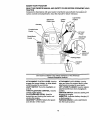
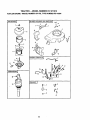
Owner's Manual
CRnFTXMnN
o
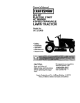
15.5 HP
ELECTRIC START
42" MOWER
6 SPEED TRANSAXLE
LAWN TRACTOR
Model No.
917.271012
•
•
•
•
Safety
Assembly
Operation
Maintenance
• Repair Parts
CAUTION:
Read and follow all
Safety Rules and Instructions
before operating this equipment.
For answers to your questions
about this product, Call:
1-800o659-5917
Sears Craftsman Help Line
5 am * 5 pro, Mon - Sat
Sears, Roebuck and Co., Hoffman Estates, IL 60179
i....
Prod_t
........
Maintenance ................................
_......._18
Service and Adjustments ...................... 22
Storage .................................................
28
Troubleshooting ....................................
29
Repair Parts .........................................
34
Parts Ordering ....................... Back Cover
2
€
5
.....
,jl, .......
....8
..... 4 ......... 12
..... ., ......... 18
IMAN RIDING
i
!
not
EQUIPMENT
if this Craftsm_
R__ing Equipment is main=gto the instructions in the owner's manual,
charge, any parts found to be defective in material or
;
covei': i
=
which become worn during normal use, such as blades, spark
plug_, air';cle_ners, belts, etc.
• Tire replacement or repair caused by punctures from outside objects, such as nails,
thoms, stumps, or glass.
• Repairs necessary because of operator abuse, negligence, improper storage or accident or the failure to maintain the equipment according to the instructions contained in
the owner's manual.
• Riding equipment
LIMITED
used for commercial or rental purposes.
90 DAY WARRANTY
ON BATTERY
For ninety (90) days from date of purchase, if any batten/included with this riding equipment proves defective in material or workmanship and our testing determines the battery will not hold a charge, Sears will replace the batten/at no charge. In-home warranty
service on your Craftsman riding equipment is available at no charge for 30 days from
the date of purchase. Please contact your nearest service center. After 30 days from the
date of purchase, warranty service is available by taking your Craftsman riding equipment to your nearest Sears Service Center. (In-home warranty service will still be available after 30 days from the date of purchase but a standard trip charge will apply). This
warranty applies only while this product is in the United States. This Warranty gives you
specific legal rights, and you may also have other rights which may van/from state to
state.
Sears, Roebuck
and Co., D/817 WA, Hoffman
GENERAL OPERATION
Estates,
IL 60179
• Never carrypassengers.
• Do not mow in reverse unless absolute-
• Read, understand, and follow all instructions in the manual and on the machine
ly necessary. Always look down and
behind before and while backing.
• Be aware of the mower discharge direction and do not point it at anyone. Do
not operate the mower without either
the entire grass catcher or the guard in
place.
• Slow down before fuming.
• Never leave a running machine unattended. Always turn off blades, set parking brake, stop engine, and remove
keys before dismounting.
before starting.
• Only allow responsible adults, who are
familiar with the instructions, to operate
the machine.
• Clear the area of objects such as rocks,
toys, wire, etc., which could be picked
up and thrown by the blade.
• Be sure the area is clear of other people
before mowing. Stop machine if anyone
enters the area.
2
•Tum off blades
when not mowing.
• Stop engine before removing grass
catcher or unclogging chute.
• Mow only in daylight or good artificial
light.
• Do not operate the machine while under
the influence of alcohol or drugs.
• Watch for traffic when operating near or
crossing roadways.
• Use extra care when loading or unloading the machine into a trailer or truck.
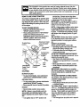
SLOPE
• DonottrytostabilizethemachTnebrt
putting your foot on the ground.
• Do not use grass catcher on steep
slopes.
CHILDREN
Tragic accidents can occur if the operator
is not alert to the presence of children.
Children are often attracted to the
machine and the mowing activity. Never
assume that children will remain where
you last sawyers.
• Keep children out of the mowing area
and under the watchful care of another
responsible adult.
• Be alert and turn machine off if children
enter the area.
OPERATION
Slopes are a major factor related to lossof-control and tipover accidents, which
can result in severe injury or death. All
slopes require extra caution. If you cannot
back up the slope or if you feel uneasy on
it, do not mow it.
DO:
• Before and when backing, look behind
and down for small children.
• Never carry children. They may fall off
and be seriously injured or interfere with
safe machine operation.
• Never allow children to operate the
machine.
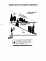
• Mow up and down slopes, not across.
• Remove obstacles such as rocks, tree
limbs, etc.
• Watch for holes, ruts, or bumps. Uneven
terrain could overtum the machine. Tall
• Use extra care when approaching blind
corners, shrubs, trees, or other objects
that may obscure vision.
grass can hide obstacles.
• Use slow speed. Choose a low gear so
that you will not have to stop or shift
while on the slope.
• Follow the manufacturer's recommen-
SERVICE
• Use extra care in handling gasoline and
other fuels. They are flammable and
vapors are explosive.
Use only an approved container.
Never remove gas cap or add fuel
with the engine running. Allow engine to cool before refueling. Do not
smoke.
Never refuel the machine indoors.
Never store the machine or fuel
container inside where there is an
dations for wheel weights or counterweights to improve stability.
• Use extra care with grass catchers or
other attachments. These can change
the stability of the machine.
• Keep all movement on the slopes slow
and gradual. Do not make sudden
changes in speed or direction.
• Avoid starting or stopping on a slope. If
tires lose traction, disengage the blades
and proceed slowly straight down the
slope.
DO NOT:
open flame, such as a water heater.
• Never run a machine inside a closed
area.
• Keep nuts and bolts, especially blade
attachment bolts, tight and keep equipment in good condition.
• Never tamper with safety devices.
Check their proper operation regulady.
• Keep machine free of grass, leaves, or
other debris build-up. Clean oil or fuel
spillage. Allow machine to cool before
storing.
• Stop and inspect the equipment if you
strike an object. Repair, if necessary,
• Donotturn
on slopes unless necessary,
and then, turn slowly and gradually
downhill, if possible.
• Do not mow near drop-offs, ditches, or
embankments. The mower could suddenly turn over it a wheel is over the
edge of a cliff or ditch, or if an edge
caves in.
• Do not mow on wet grass. Reduced
traction could cause sliding.
3
beforerestarting.
• Never make adjustments or repairs with
the engine running.
• Grass catcher components are subject
to wear, damage, and deterioration,
which could expose moving parts or
allow objects to be thrown. Frequently
check components and replace with
manufacturer's recommended parts,
when necessary.
• Mower blades are sharp and can cut.
Wrap the blade(s) or wear gloves, and
use extra caution when servicing them.
• Check brake operation frequently.
Adjust and service as required.
Mow up and down slopes (15 ° Max), no1
• Be sure the area is clear of other people
before mowing. Stop machine if anyone
enters the area.
• Never carry passengers.
• Do not mow in reverse unless absolute-
across.
Remove obstacles such as rocks, tree
limbs, etc.
Watch for holes, ruts, or bumps. Unever
terrain could overturn the machine. Taft
ly necessary. Always look down and
behind before and while backing.
• Never carry children. They may fall off
and be seriously injured or interfere with
safe machine operation.
• Keep children out of the mowing area
and under the watchful care of another
grass can hide obstacles.
Use slow speed. Choose a low gear so
that you will not have to stop or shift
while on the slope.
Avoid starting or stopping on a slope. If
tires lose traction, disengage the blades
and proceed slowly straight down the
slope.
Do notturn on slopes unless necessary,
and then, turn slowly and gradually
downhill, if possible.
responsible adult.
• Be alert and turn machine off if children
enter the area.
• Before and when backing, look behind
and down for small children.
_,WARNING:
The engine exhaust from
this product contains chemicals known to
the State of California to cause cancer,
birth defects, or other reproductive harm.
,_Look for this symbol to point out important safety precautions. It means CAUTION!!! BECOME AWARE!!! YOUR SAFETY IS INVOLVED.
_.CAUTION:
In order to prevent acciden-
tal starting when setting up, transporting,
adjusting or making repairs always disconnect spark plug wire and place wire where
it cannot contact spark plug.
4
PRODUCT
SPEGIFICATiONS
GASOLINE
CAPACITY
AND TYPE:
1.25 GALLONS
UNLEADED
REGULAR
OIL TYPE
SAE 10W-30
API-SF/SG/SH):
Should you experience any problem you
cannot easily remedy, please contact your
nearest Sears Authorized Service Center.
We have competent, well-trainea tecSniclans and the proper tools to service or
repair this tractor.
Please read and retain this manual. The
(above 32°F)
SAE 5W-30
instructions will enable you to assemble
and maintain your tractor properly. Always
observe the "SAFETY RULES".
(below 32°F)
OIL CAPACITY:
W/FILTER: 4.0 PINTS
W/O FILTER: 3.5 PINTS
SPARK PLUG:
GAP: .040")
MAINTENANCE AGREEMENT
A Sears Maintenance Agreement is available on this product. Contact your nearest
Sears stor,a,_r,,_etails.
Champion RC12YC
VALVE CLEARANCE:
NOT ADJUSTABLE
GROUND SPEED
FORWARD:
(MPH):
1sT
2ND
3RD
4 TM
5TM
6TM
REVERSE:
CUSTOMER
• Read and observe the safety nJles.
• Follow a regular schedule in maintaining, caring for and using your tractor.
• Follow the instructions under =Mainte-
1.1
1.4
2.3
3.5
4.5
6.0
1,7
TIRE PRESSURE:
FRONT: 14 PSI
REAR: 10 PSI
CHARGING
SYSTEM:
3 AMPS BATTERY
5 AMPS HEADLIGHTS
BATTERY:
AMP/HR: 30
MIN. CCA: 240
CASE SIZE: UIR
BLADE BOLT
TORQUE:
27-35 FT. LBS.
RESPONSIBILITIES
nance" and "Storage"
owner's manual.
,_,WARNING:
sections of this
This tractor is equipped
with an internal combustion engine and
should not be used on or near any unimproved forest-covered,
brush-covered or
grass-covered land unless the engine's
exhaust system is equipped with a spark
arrester meeting applicable local or state
laws (if any). If a spark arrester is used, it
should be maintained in effective working
order by the operator.
In the state of California the above is
required by law (Section 4442 of the
California Public Resources Code). Other
states may have similar laws. Federal
laws apply on federal lands. A spark
arrester for the muffler is available through
your nearest Sears Authorized Service
Center (See REPAIR PARTS section of
this manual).
CONGRATULATIONS
on your purchase
of a Craftsman Tractor. It has been
designed, engineered and manufactured
to give you the best possible dependability
and performance.
5
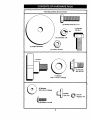
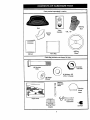
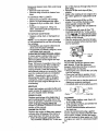
Parts Bag _:ontents shown full size
(1) Hex Bolt 5/16-18 x 1-1/4
©
(1) Hex Bolt
3/8-16 x I
(1) Lockwasher 3/8
@
(1) LargeFlat Washer
(1) Locknut 5/16-18
(1) Knob
(1) Shoulder
Bolt 5/16-18
(1) Washer
17/32 x 1-3/16 x 12 Gauge
O
(2) Washers
3/16 x 3/4 x 16 Gauge
(2) Weld
Nuts #10
(2)__
#10 x 5/8
6
(2)
Lock #10
Washers
Parts packed separately in carton
Steedng
Boot
Seat
Video
Cassette
Mulcher
Plate
i
j
I
t
I
I
I
I
I
j,
Steedng
Wheel
I
Parts Bag
Manual
Parts Bag contents not shown full size
D
(2) Shoulder
Bolts
(2) Washers 3/8
x 7/8 x 14 Gauge
Wheels
Steering
Sha_
Wheel
t
Insert
E_ension
Latch
.'oo
Slope Sheet
Assemblies
Steering Wheel
(2) Keys
Adapter
7
Yournew
tractor has been assembled at the factory with exception of those parts left
unassembled
for shipping purposes. To ensure safe and proper operation of your tractor
all parts and hardware you assemble must be tightened securely. Use the correct tools
as necessary to insure proper tightness. Review the video cassette before you begin.
TOOLS REQUIRED FOR
ASSEMBLY
Insert
A socket wrench set will make assembly
easier. Standard wrench sizes you need
are listed below.
(1) 9/16" wrench
(1) 3/4" Socket w/
(1) Pliers
drive ratchet
(2) 112" wrench
(1) Phillips Screw(1) Utility knife
driver
(1) Tire pressure gauge
When right or left hand is mentioned in
this manual, it means, from your point of
view, when you are in the operating position (seated behind the steering wheel).
TO REMOVE
CARTON
UNPACK
TRACTOR
_ ,_3/8
Large Flat
ff--_Washer
Steedng_'_,___
Adapter
FROM
CARTON
Extension
Shaft
Lower
Steering Shaft
WHEEL
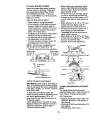
ASSEMBLE EXTENSION SHAFT AND
BOOT
Hex Bolt
<',
,"
.
,
,,<-,,
-'1-
,
\
,,
I
.
,
,,, ,"
Tab
Slots
TO ROLL TRACTOR OFF SKID (See
Operation section for location and
function of controls)
• Press lift lever plunger and raise attachment lift lever to its highest position.
• Release parking brake by depressing
clutch/brake pedal.
• Place gearshift lever in neutral (N) position.
• Roll tractor forward off skid.
shaft onto lower steer-
ing shaft. Align mounting holes in extension and lower shafts and install 5/16
hex bolt and Iocknut. Tighten securely.
IMPORTANT:
Tighten bolt and nut securelyto 18-22 ft. Ibs. torque.
• Place tabs of steedng boot over tab
slots in dash and push down to secure.
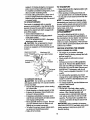
INSTALL STEERING
._5/16
washer. 3/8 hex belt and tighten securely.
• Snap steering wheel insert into center
of steering wheel.
• Remove protective materials from tractor hood and grill.
IMPORTANT: Check for and remove any
staples in skid that may puncture tires
where tractor is to roll off skid.
BEFORE ROLLING TRACTOR OFF
SKID
• Slide extension
_Tabs
5/16 Locknut _
STEERING
)
Steering
• Remove all accessible loose parts and
parts boxes from shipping carton (See
page 6).
• Cut, from top to bottom, along lines on
all four comers of shipping carton, and
lay panels flat.
• Check for any additional loose parts or
boxes and remove.
ATTACH
3/8 Rex
Bolt
L_:_l_asher
WHEEL
• Position front wheels of the tractor so
they are pointing straight forward.
• Slide steering wheel adapter onto steering shaft extension.
• Position steedng wheel so cross bars
are horizontal (left to dght) and slide
inside boot and onto adapter.
• Assemble large flat washer, 3/8 lock
• Remove banding holding discharge
guard up against tractor.
8
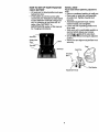
HOW TO SET UP YouR
CHECK BATTERY
TRACTOR
INSTALL
Adjust seat before tightening adjustment
knob.
• Lift seat pan to, raised position and open
battery box door.
• If this battery is put into service after
month and year indicated on label (label
located between terminals) charge battery for minimum of one hour at 6-10
amps. (See "BATTERY" in
MAINTENANCE
section of this manual
• Remove cardboard packing on seat pan.
• Place seat on seat pan and assemble
shoulder bolt. Tighten shoulder bolt
securely.
• Assemble adjustment knob and flat
washer loosely. Do not tighten.
• Lower seat into operating position and
sit on seat.
for charging instructions).
• Slide seat until a comfortable position is
reached which allows you to press
clutch/b_._ke _o_dal all the way down.
• Get off _e-_t _Tthout moving its adjusted
position.
• Raise seat and tighten adjustn_ent knob
securely.
Seat Pan
Battery Box
Door
SEAT
Label
Seat
Seat Pan
: to,0o,
/
Flat Washer
Adjustment Knob
9
CHECK TIRE PRESSURE
The tires on your tractor were overinflated.
at the factory for shipping purposes.
Correct tire pressure is important for best
cutting performance.
• Reduce tire pressure to PSI shown in
=PRODUCT SPECIFICATIONS"
section
of this manual.
CHECK
Weld Nut From
The Top
Weld
Hook Ppints
Down •
Lock
Washer
Latch
Latch
DECK LEVELNESS
For best cutting results, mower housing
should be properly leveled. See =TO
LEVEL MOWER HOUSING" in the
Service and Adjustments section of this
manual.
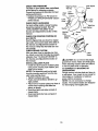
CHECK FOR PROPER
ALL BELTS
POSITION
Washer
Lock Washer
Washer
Mulcher
"_1_ Screw
Plate
_
_..
Deflector
Shield
OF
See the figures that are shown for replacing motion and mower blade drive belts in
the Service and Adjustments sectoin of
this manual. Verify that the belts are routed correctly.
CHECK BRAKE SYSTEM
After you leam how to operate your tractor, check to see that the brake is properly
adjusted. See "TO ADJUST BRAKE" in
the Service and Adjustments section of
this manual.
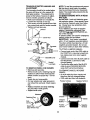
INSTALL MULCHER PLATE
• Install two latch hooks to mulcher plate
using screw, washer, lock washer, and
weld nut as shown.
NOTE: Pre-assemble weld nut to latch
Latch
Hooks
_.CAUTION:
Do not remove discharge
guard from mower. Raise and hold guard
when attaching mulcher plate and allow it
to rest on plate while in operation.
TO CONVERT TO BAGGING OR
DISCHARGING
Simply remove mulcher plate and store in
a safe place. Your mower is now ready for
discharging or installation of optional
grass catcher accessory.
NOTE: It is not necessary to change
blades. The mulcher blades are designed
for discharging and bagging also.
hook by inserting weld nut from the top
with hook pointing down.
• Tighten hardware securely.
• Raise and hold deflector shield in upright position.
• Place front of mulcher plate over front of
mower deck opening and slide into
place, as shown.
• Hook front latch into hole on front of
mower deck.
• Hook rear latch into hole on back of
mower deck.
10
ASSEMBLEGAUGEWHEELSTO
MOWERDECK
The gaugewheelsaredesignedto keep
the mowerdeck in properpositionwhen
operatingmower.Besurethey are properly adjustedto ensure optimum mower per-
CHECKLIST
- Please review the following checklist:
- / All assembly instructions have been
completed.
J No remaining loose parts in carton.
/ Battery is propedy prepared and
formance.
charged. (Minimum 1 hour at 6 amps).
• Assemble gauge wheels with tractor on
/ Seat is adjusted comfortably and tighta flat level surface.
ened securely.
• Adjust mower to desired cutting height
/ All tires are propedy inflated. (For ship(See "TO ADJUST MOWER CUTTING
ping purposes, the tires were ovednflatHEIGHT" in the Operation section of this
ed at the factory).
manual).
J Be sure mower deck is properly leveled
• With mower in desired height of cut poside-to-side/front-to-rear
for best cutting
sition, gauge wheels should be assemresults. (T'_rr_
be properly inflated
bled so they are slightly off the ground.
for leveling).
Install gauge wheel in appropriate hole
/ Check mower and drive belts. Be_ure
with shoulder bolt, 3/8 washer, and 3/8they are routed properly around pulleys
16 Iocknut and tighten securely.
and inside all belt keepers.
• Repeat for opposite side installing
,/Check wiring. See that all connections
gauge wheel in same adjustment hole.
are still secure and wires are propedy
clamped.
While learning how to use your tractor, pay
extra attention to the following important
items:
Gauge Wheel
Mounting Bracket
J Engine oil is at proper level.
/ Fuel tank is filled with fresh, clean, regular unleaded gasoline.
/ Become familiar with all controls - their
3/8-16 Locknu
Shoulder
Bolt
3/8
location and function. Operate them
before you start the engine.
,/Be sure brake system is in safe operating condition.
Gauge Wheel
11
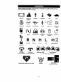
These symbols may appear on your tractor or in literature supplied
Learn and understand their meaning.
with the product-:
BA'R'ERY
CAUTION OR
WARNING
REVERSE
FORWARD
FAST
ENGINE ON
ENGINE OFF
OIL PRESSURE
CLUTCH
UGHTS ON
FUEL
MOWER HEIGHT
DIFFERENTIAL
PARKING BRAKE
LOCK
LOCKED
L
R N
REVERSE
MOWER
OVER TEMP
LIGHT
==_=
CHOKE
!
SLOW
NEUTRAL
H
L
HIGH
LOW
UNLOCKED
PARKING BRAKE
LIFT
ATTACHMENT
CLUTCH ENGAGED
ATTACHMENT
CLUTCH DISENGAGED
KEEP AREA CLEAR
SLOPE HAZARDS
(SEE SAFETY RULES SECTION)
IGNITION
DANGER, KEEP HANDS AND FEET AWAY
12
FREE WHEEL
(Automatic Models only)
KNOW YOUR TRACTOR
READ THIS OWNER'S MANUAL AND SAFETY RULES BEFORE OPERATING YOUR
TRACTOR
Compare the illustrations with your tractor to familiarize yourself with the Iocaiions of
various controls and adjustments. Save this manual for future reference,
Attachment
Clutch Lever
Ignition
Switch
Light Switch
Position
Ammeter
Throttle/Choke
Control
Lift Lever
Plunger
Clutch/Brake
Control
Attachment
Lever
Height
Adjustment
Indicator
"Parking Brake
Gearshift
Lever
Our tractors
ATTACHMENT
CLUTCH
conform to the safety standards of the American
National Standards Institute.
LEVER:
Used to
ATTACHMENT
LIFT LEVER: Used to
raise and lower the mower deck or other
engage the mower blades, or other attachments mounted to your tractor.
LIGHT SWITCH: Turns the headlights on
and off.
THROTTLE/CHOKE
CONTROL: Used to
control engine speed.
CLUTCH/BRAKE
PEDAL:
attachments mounted to your tractor.
LIFT LEVER PLUNGER: Used to release
attachment lift lever when changing its
position.
IGNITION SWITCH: Used for starting and
stopping the engine.
AMMETER:
Indicates battery charging (+)
or discharging (-).
PARKING BRAKE: Locks clutcWbrake
Used for
declutching and braking the tractor and
starting the engine.
GEARSHIFT
LEVER: Selects the speed
and direction of the tractor.
into the brake position.
13
The operatiohof anytractorcan resultin foreignobjectsthrownintothe
eyes, which can result in severe eye damage. Always wear safety glasses
or eye shields while operating your tractor or performing any adjustrfient_ or
repairs. We recommend a wide vision safety mask over spectacles, or standard safety glasses.
HOW TO USE YOUR TRACTOR
remove key. Always remove key when
leaving tractor to prevent unauthorized use.
• Never use choke to stop engine.
IMPORTANT: Leaving the ignition switch in
any posiSen other than "OFF" will cause the
battery to be discharged, (dead).
Yourtractoris equippedwithan operatorpresence sensingswitch.When engine is running,
anyattemptby the operatorto leavethe seat
withoutfirstsetting theparking brakewillshut
offthe engine.
NOTE: Under certain conditions when tractor
is standing _]be
engine running, hot
engine exhaust gases may cause "browning"
of grass. To eliminate this poss4bility, always
stop engine when stopping tractor on grass
TO SET PARKING BRAKE
• Depress dutch/brake pedal into full
=BRAKE" position and hold.
• Place parking brake lever in "EN-GAGED"
position and release pressure from
dutch/brake pedal. Pedal should remain in
"BRAKE" position. Make sure parking
brake will hold tractor secure.
areas.
A CAUTION: Always stop tractor completely, as described above, before leaving the
oporatofs position; to empty grass catcher,
etc.
THROTrLE CONTROL
Attachment Clutch
Lever "Engaged"
Position
Throttle/Choke
Control
Always operate engine at full throttle.
• Operating engine at less than full throttle
reduces the battery charging rate.
• Full throttle offers the best bagging and
mower performance.
TO MOVE FORWARD AND BACKWARD
__/=Disengaged"Position
Brake_"
Position
_" _-_;'_:_
/
; _._ ; --_-_"
"_,,"; 2 _.'-'_'::Y- ",_
'$
..
__
_'_
'"
%Dis/_
Clutch/Bral _e
Pedal =Ddve"
Position
Position
Parking Brake
The direction and speed of movement is controlled by the gearshift lever.
• Start tractor with clutch/brake pedal
depressed and gearshift lever in neutral (N)
position.
• Move gearshift lever to desired position.
• Slowly release dutch/brake pedal to start
movement.
Position
j"Engaged"
Shift
Gealr
Lever
IMPORTANT: Bring tractor to a complete
stop before shifting or changing gears. Failure
to do so will shorten the useful life of your
transaxle.
TO ADJUST MOWER CuI-rlNG HEIGHT
STOPPING
MOWER BLADES -
• To stopmowerblades, moveattachment
dutch lever to =DISENGAGED"_.
GROUND
The position of the attachment liftlever determines the cutting heighL
• Grasp liff lever.
• Press plunger with thumb and move lever
DRIVE -
• To stop ground drive, depress dutch/brake
pedal into full "BRAKE" position.
• Move gearshift levertoneutmt(N)position.
todesiredpos_on.
The cutting height range is approximately 11/2 to 4". The heights are measured from the
ground to the blade tip with the engine not
running. These heights are approximate and
may vary depending upon soil conditions,
height of grass and types of grass being
mowed.
• The average lawn should be cut to approxi-
ENGINE • Move throttle controlto slowposition.
NOTE: Falure to movethrottle controlto
slowpositionand allowingengineto idle
beforestopping may cause engine to "backfire".
• Turn ignition key to "OFF" position and
14
mately2-1/2
inches during the cool season
and to over 3 inches during hot months.
For healthier and better looking lawns, mow
often and after moderate growth.
• For best cutting performance, grass over 6
inches in height should be mowed twice.
Make the first cut relatively high; the second
to desired height.
TO OPERATE MOWER
Your tractor is equipped with an operator
presence sensing switch. Any attempt by the
operator to leave the seat with the engine running and the attachment clutch engaged will
shut off the engine.
• Select desired height of cut.
• Start mower blades by engaging attachment clutch control.
• TO STOP MOWER BLADES - disengage
attachment clutch control.
,A CAUTION: Do not operate the mower
without either the entire grass catcher, on
mowers so equipped, or the discharge guard
in place.
TO TRANSPORT
• Raise attachment liftto highest position with
attachment liftcontrol.
• When pushing or towing your tractor, be
sure gearshift lever is in neutral (N) position.
• Do not push or tow tractor at mere than five
(5) MPH.
NOTE: To protect hood from damage when
transporting your tractor on a truck or a trailer,
be sure hood is closed and secured to tractor.
Use an appropriate means of _ng hood to
tractor (rope, cord, etc.).
TOWING
CARTS AND OTHER
A'FrACHM_
Tow only the attachments that are recommended by and comply with specificati-0ns of
the manufacturer of your tractor. Use common
sense when towing. Too heavy of a load,
while on a slope, is dangerous. "Tires can lose
traction with the ground and cause you to lose
control of your tractor.
BEFORE STARTING THE ENGINE
CHECK ENGINE OIL LEVEL
Attachment Clutch
Position
"Disengaged"
Attachment Lift
Lever High Position
Low
TO OPERATE ON HILLS
_,CAUTION:
Do not drive up or down hills
with slopes greater than 15 ° and do not drive
across any slope.
• Choose the slowest speed before starting
up or down hills.
• Avoid stopping or changing speed on hills.
• If slowing is necessary, move throttle controf lever to slower position.
• If stopping is absolutely necessary, push
clutch/brake pedal quickly to brake pos'_ion
and engage parking brake.
• Move gearshift lever to 1st gear. Be sure
you have allowed room for tractor to roll
slightly as you restart movement.
• To restart movement, slowly release parking brake and clutch/brake pedal.
• Make all turns slowly.
• The engine in your tractor has been
shipped, from the factory, already filled with
summer weight oil.
• Check engine oil with tractor on level
ground.
• Unthread and remove oil fillcap/dipstick;
wipe oil off. Reinsert the dipstick into the
tube and rest oil fill cap on the tube. Do not
thread the cap onto the tube. Remove and
read o_ level. If necessary, add oil unt='l
=FULL" mark on dipstick is reached. Do not
overfill.
• For cold weather operation you should
change oil for easier starting (See "OIL VISCOSITY CHART" in the Maintenance section of this manual).
• To change engine oil, see the Maintenance
section in this manual.
ADD GASOUNE
• Fill fuel tank. Use fresh, clean, regular
unleaded gasoline with a minimum of 87
octane. (Use of leaded gasoline will
increase carbon and lead oxide depos'_s
and reduce valve life). Do not mix oil with
gasoline. Purchase fuel in quantities that
can be used within 30 days to assure fuel
freshness.
IMPORTANT: When operating in temperatures below 32°F(0°C), use fresh, clean wintel
grade gasoline to help insure good cold
weather starting.
15
_,WARNING:
F_x_rlenoe indicates that
alcohol blended fuels (called gesohel or using
ethanol or methanol) can attract moisture
which leads to separation and formation of
adds during storage. Acidic gas can damage
the fuel system of an engine while in storage.
To avoid engine problems, the fuel system
should be emptied before storage of 30 days
or longer. Drain the gas tank, start the engine
and let it run until the fuel lines and carburetor
are empty. Use fresh fuel next season. See
Storage Instructionsfor additional information.
Never use engine or carburetor cleaner products in the fuel tank or permanent damage
yo=ur.
AUTION: Fill to bottom of gas tank tiller
neck. Do not overfill. Wipe off any spilled oil or
fuel. Do not store, spill or use gasoline near
an open flame.
TO START ENGINE
When starting the engine for the first time or if
the engine has run out of fuel, itwill take extra
cranking time to move fuel from the tank to
the engine.
• Sit on seat in operating position, depress
clutctvbrake pedal and set parking brake.
• Place gear shift lever in neutral (N) position.
• Move attachment clutch to "DISENGAGED" position.
• Move throttle control to choke position.
• When engine starts, allow engine to run
with _e throttl e control in the choke position
until the engine rune roughly, therLmove
throttle control to fast position. This may
require an engine warm-up period from
several seconds to several minutes,
depending on the temperature.
• The attachments can also be used during
the engine warm-up peded.
NOTE: If at a high altitude (above 3000 feet)
or in cold temperatures (below 32 F) the carburetor fuel mixture may need to be adjusted
for best engine performance. See "TO
ADJUST CARBURETOR" in the Service and
Adjustmen('_
of this manual.
MOWING TIPS
• "Erechains cannot be used when the
mower housing is attached to tractor.
• Mower should be properly leveled for best
mowing performance. See "TO LEVEL
MOWER HOUSING" in the Service and
Adjustments section of this manual.
• The left hand side of mower should be
used for trimming.
• Drive so that clippings are discharged onto
the area that has been cuL Have the cut
•
NOTE: Before starting, read the warm and
cold starting procedures below.
• Insert key into ignition and rum key dockwise to "START" pos'tion and release key
as soon as engine starts. Do not run starter
continuously for more than fifteen seconds
per minute. If the engine does not start after
several attempts, move throttle control to
fast position, wait a few minutes and try
again. If engine still does not start, move
the throttle control back to the choke pooi-
•
•
tlon and retry.
WARM WEATHER STARTING (50 ° FAND
ABOVE)
•
• When engine starts, move the throttle control to the lest position.
• The attachments and ground drive can now
be usecl. If the engine clnes not accept the
load, restart the engine and allow it to warm
up for one minute using the choke as
described above.
•
COLD WEATHER STARTING ( 5@' FAND
BELOW)
16
area to the right of the tractor. This will
result in a more even distributionof clippings and more uniform cutting.
When mowing large areas, start by tuming
to the right so that clippings will discharge
away from shrubs, fences, driveways, etc.
After one or two rounds, mow in the opposite direction making left hand turns until finished.
If grass is extremely tall, it should be
mowed twice to reduce load and possible
tire hazard from dried clippings. Make first
cut relatively high; the second to the
desired height.
Do not mow grass when it is wet. Wet
grass will plug mower and leave undesirable clumps. Allow grass to dry before
mowing.
Always operate engine at full throttle
when mowing to assure better mowing
performance and proper discharge of materlal. Regulate ground speed by selecting a
low enough gear to give the mower the
best cutting performance as well as the
quality of cut desired.
When operating attachments, select a
ground speed that will suit the terrain and
give best performance of the attachment
being used.
• For best results, adjust the mower cutting
heightso that the mower cuts off onlythe
top one-third of the grass blade=s=.
For extremely heavy mulching, reduce your width
of cut on each pass and mow slowly.
• Certain types of grass and grass conditions
may require that an area be mulched a
second time to completely hide the clippings. When doing a second cut, mow
across or perpendicular to the first cut path.
• Change your cutting pattem from week to
week. Mow north to south one week then
J
MULCHING
MOWING TIPS
IMPORTANT: For best performance, keep
mower housing free of built-up grass and
trash. Clean after each use.
change to east to west the next week. This
will help prevent matting and graining of the
lawn. -'='_- "_
• The special mulching blade will recut the
grass clippings many times and reduce
them in size so that as they fall onto the
lawn they will disperse into the grass and
not be noticed. Also, the mulched grass will
biodegrade quickly to provide nutrients for
the lawn. Always mulch with your highest
engine (blade) speed as this will provide
the best recutting action of the blades.
• Avoid cutting your lawn when it is wet. Wet
grass tends to form clumps and interferes
with the mulching action. The best time to
mow your lawn is the early afternoon. At
this time the grass has dried and the newly
cut area will not be exposed to the direct
sun.
17
CUSTOMER RESPONSIBILITIES
MAINTENANCE
SCHEDULE
:
"
f _"___-_-_
._y
AS YOU COMPLETE
Check Tire
Brakepressure
Operation
Check
T
_
Check Operator Presence and
Interlock
Systems
V p
R
T
Sharpen/Replace Fasteners
Mower Blades
CheckforLoo6e
R
0
Clean Battery and Terminals
Check Battery Level
Check Transaxle Cooling
Lubrication
Adjust
Blade Belt(s)
Motion
Check
Engine
Ik/s
Oil Level
Engine
IJ_
V'
Oil
I#_1_
N
Clean Air Screen
Inspect MuffledSpark
Air Filter
V'=
Attester
If
Oil Filter (If equipped)
Engine
Cooling
i 11_1.2
Fins
Replace
Air Filter Paper
Replace
Fuel Filter
li_=
_=
Cartrldge
The warranty on this tractor does not cover
items that have been subjected to operator
abuse or negligence. To receive full value
from the warranty, operator must maintain
tractor as instructed in this manual. Some
adjustments will need to be made periodically to properly maintain your tractor.
All adjustments in the Service and
Adjustments section of this manual should
be checked at least once each season.
• Once a year you should replace the
spark plug, clean or replace air filter, and
check blades and belts for wear. A new
spark plug and clean air filter assure
proper air-fuel mixture and help your
engine run better and last longer.
•
•
•
•
temperatur os.
USE
Check engine oil level.
Check brake operation.
Check tire pressure.
Check operator presence and interlock
systems for proper operation.
• Chock for loose fasteners.
5 - If equipped with ad_tJstab_e system.
6 - Not requ_
if equipped wlth maintenance-free
battery.
7 - T'_ht en front axle pivot bolt to 35 ft.-Ibs, rnaxln-um,
Do not cvertighten.
LUBRICATION CHART
RECOMMENDATIONS
EACH
I# #
ll_
1 * Change mo_ often when c_erati_g under • heavy Joad or in high ambient
2 - Service mo(e often when operating irl dirty Or dusty conditions.
3 - If equipped wl_l ct"_fi#er, change omever/S0
hours.
4 o Replace b;ade= more ofl_ when mowing in sandy soil.
BEFORE
I_
_2
Replace Spark plug
GENERAL
- -='==_."_
i _/_
G
Clean
If
_
Tension
Clean
Replace
11_7
Drive Belt(s) Tension
E
E
_,1,
V*
Adjust
Change
Ik/
Chart
Zerk
0 Front Wheel
Wheel
Bearing
Zerk
Bearing Zerk
0 Engine
O Attachmenl: ;
Clutch
ri ,
I
Pivot(s)
',
,
•-"
Shift
Pivots
O SAE 30 or 10w30 Motor OIL
O General Purpose Grease
O Refer to Maintenance "Engine" Section
IMPORTANT: Do not oil or grease the pivot
points which have special nylon bear-ings.
Viscous lubricants will attract dust and dirt
that will shorten the life of the self-lubdcating
beadngs. If you feel they must be lubdcated,
use only a dry, powdered graphite type lubdcant sparingly.
18
TRACTOR
Alwaysobservesafetyrulesyvhen
per-
forming any maintenance.
BRAKE OPERATION
If tractor requires more than six (6) feet
stopping distance at high speed in highest
gear, then brake must be adjusted. (See
"TO ADJUST BRAKE" in the Service and
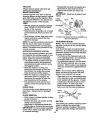
• Reassemble he_( bolt, lock washer and
flat washer in exact order as shown.
• Tighten bolt securely (27-35 Ft. Lbs. torque).
IMPORTANT:
Blade bolt is grade 8 heat
treated.
Trailing
Edge Up
Blade
Adjustments section of this manual).
TIRES
• Maintain proper air pressure in all tires
(See "PRODUCT SPECIFICATIONS"
section of this manual).
• Keep tiros free of gasoline, oil, or insect
control chemicals which can harm rubber.
• Avoid stumps, stones, deep ruts, sharp
objects and other hazards that may
cause tire damage.
NOTE: To seal tire punctures and prevent
flat tires due to slow leaks, tire sealant
may be purchased from your local parts
dealer. Tire sealant also prevents tire dry
rot and corrosion.
OPERATOR
PRESENCE
SYSTEM
Be sure that operator presence and interlock systems are working properly, if your
tractor does not function as described
below, repair the problem immediately.
• The engine should not start unless the
clutch/brake pedal is fully depressed
and attachment clutch control is in the
disengaged position.
• When the engine is running, any
attempt by the operator to leave the
seat without first setting the parking
brake should shut off the engine.
• When the engine is running and the
attachment clutch is engaged, any
attempt by the operator to leave the
seat should shut off the engine.
• The attachment clutch should never
operate unless the operator is in the
seat.
BLADE CARE
For best results mower blades must be
kept sharp.
blades.
BLADE
Replace bent or damaged
REMOVAL
Star
\
Center
Hole
Lock
Mandrel
Assembly
_._._
Hex Bolt
(Grade 8)*
"A Grade 8 heat treated bolt can be identified by six
lines on the bolt head,
TO SHARPEN
BLADE
NOTE: We do not recommend sharpening blade but if you do, be sure the blade
is balanced.
Care should be taken to keep the blade
balanced. An unbalanced blade will cause
excessive vibration and eventual damage
to mower and engine.
• The blade can be sharpened with a file
or on a grinding wheel. Do not attempt
to sharpen while on the mower.
• To check blade balance, you will need a
5/8" diameter steel bolt, pin, or a cone
balancer. (When using a cone balancer,
follow the instructions supplied with balancer.)
NOTE: Do not use a nail for balancing
blade, the lobes of the center hole may
appear to be centered, but are not.
• Slide blade on to an unthreaded portion
of the steel bolt or pin and hold the bolt
or pin parallel with the ground. If blade
is balanced, it should remain in a horizontal position. If either end of the
blade moves downward, sharpen the
heavy end until the blade is balanced.
Center
,_=...
/,/
Hole _Blade
5/8.olt
• Raise mower to highest position to allow
or Pin
"_
access to blades.
• Remove hex bolt, lock washer and flat
BATrERY
washer securing blade.
Your tractor has a battery charging system
• Install new or resharpened blade with
which is sufficient for normal use.
trailing edge up towards deck as shown.
However, periodic charging of the battery
IMPORTANT: To ensure proper assembly,
with an automotive charger will extend its
center hole in blade must align with star
life.
on mandrel assembly.
19
TO CHANGE
• Keep battery and terminals clean.
:
,- Keep battery bolts tight.
• Keep small vent holes open.
• Recharge at 6-10 amperes for 1 hour.
NOTE: The odginal equipment battery on
your tractor is maintenance free. Do not
attempt to open or remove caps or covers.
Adding or checking level of electrolyte is
not necessary.
TO CLEAN
ENGINE
OIL
Determine temperature range expected
before oil change. All oil must meet API
service classification
SF, SG, or SH.
• Be sure tractor is on level surface.
• Oil will drain more freely when warm.
• Catch oil in a suitable container.
• Remove oil fill cap/dipstick.
Be careful
not to allow dirt to enter the engine
when changing oil.
• Remove drain plug.
• After oil has drained completely, replace
oil drain plug and tighten securely.
• Refill engin e with oil through oil fill dipstick tul_.
P_r slowly. Do not overfill.
For approximate capacity see "PRODUCT SPECIFICATIONS"
section of this
manual.
• Use gauge on oil fill cap/dipstick for
checking level. Insert dipstick into the
tube and rest the oil fill cap on the tube.
Do not thread the cap onto the tube
when taking reading.
Keep oil at
"FULL" line on dipstick. Tighten cap
onto the tube securely when finished.
Cover Knob
Wing
Air Cleaner
Cover
BATTERY AND TERMINALS
Corrosion and dirt on the battery and terminals can cause the battery to =leak"
power.
• Open battery box door.
• Disconnect BLACK battery cable first
then RED battery cable and remove
battery from tractor.
• Rinse the battery with plain water and
dry.
• Clean terminals and battery cable ends
with wire brush until bdght.
• Coat terminals with grease or petroleum
jelly.
• Reinstall battery (See =REPLACING
BA'I-I'ERY" in the SERVICE AND
ADJUSTMENTS
section of this manual),
V-BELTS
Check V-belts for deterioration and wear
after 100 hours of operation and replace if
necessary. The belts are not adjustable.
Replace belts if they begin to slip from
wear.
TRANSAXLE
COOLING
Foam
PreCleaner
Grommet
Cleaner
Base
Keep transaxle free from build-up of dirt
and chaff which can restrict cooling.
ENGINE
LUBRICATION
Oil Fill
Air Cleaner
Paper
Cartridge
Only use high quality detergent oil rated
with API service classification SF, SG, or
SH. Select the oil's SAE viscosity grade
according to your expected operating temperature.
Dipstick
Oil Drain Plug
CLEAN
AIR SCREEN
Air screen must be kept free of dirt and
chaff to prevent engine damage from overheating, Clean with a wire brush or compressed air to remove dirt and stubborn
dried gum fibers.
AIR FILTER
Your engine will not run propedy using a
dirty air filter. Clean the foam pre-cleaner
after every 25 hours of operation or every
season. Service paper cartddge every
100 hours of operation or every season,
whichever occurs first.
Change the oil after every 50 hours of
operation or at least once a year if the
tractor is not used for 50 hours in one
year,
Check the crankcase oil level before starting the engine and after each eight (8)
hours of operation. Tighten oil fill cap/dip
stick securely each time you check the oil
level.
20
Service air cleaner more often under dusty
conditions.
• Remove knob and cover.
• Remove wing nut and air cleaner from
base.
TO SERVICE
•
PRE-CLEANER
• Slide foam pre-cleaner off cartridge.
• Wash it in liquid detergent and water.
• Squeeze it dry in a clean cloth. Allow it
to dry.
• Saturate it in engine oil Wrap it in
clean, absorbent cloth and squeeze to
remove excess oil.
TO SERVICE
•
•
•
CARTRIDGE
• Replace a dirty, bent, or damaged cartridge.
NOTE: Do not wash the paper cartridge
or use pressurized air, as this will damage
the cartridge.
• Reinstall the pre-cleaner (cleaned and
oiled) over the paper cartridge.
• Reassemble air cleaner, wing nut, cover
and tighten knob securely.
CLEAN AIR INTAKE/COOLING
AREAS
To insure proper cooling, make sure the
grass screen, cooling fins, and other
external surfaces of the engine are kept
clean at all times.
Every 100 hours of operation (more often
under extremely dusty, dirty conditions),
remove the blower housing and other
cooling shrouds. Clean the cooling fins
and external surfaces as necessary. Make
sure the cooling shrouds are reinstalled.
NOTE:
Operating the engine with a
blocked grass screen, dirty or plugged
cooling fins, and/or cooling shrouds removed will cause engine damage due to
overheating.
•
tion of this manual, through step remove
drain plug).
Remove oil filter and wipe off filter
adapter.
Apply a thin coating of new engine oil to
the rubber gasket on replacement oil filter.
Install replacement oil filter on filter
adapter. Turn oil filter clockwise until
rubber gasket contacts the filter
adapter, then tighten filter an additional
1/2 turn.
Fill crankcase with new oil (See "TO
CHANGE ENGINE OIL" in this section
of this _u_
For approximate capacity see _b'I_[O]_OCT SPECIFICATIONS"
section of this manual.
Start the engine and check fbr_il leaks.
Correct any leaks before placing engine
into full operation.
Filtrode
Aceite
IN-LINE FUEL FILTER
The fuel filter should be replaced once
each season. If fuel filter becomes
clogged, obstructing fuel flow to carburetor, replacement is required.
• With engine cool, remove filter and plug
fuel line sections.
• Place new fuel filter in position in fuel
line with arrow pointing towards carburetor.
• Be sure there are no fuel line leaks and
clamps are properly positioned.
• Immediatly wipe up any spilled gasoline.
MUFFLER
Inspect and replace corroded muffler and
spark arrester (if equipped) as it could create a fire hazard and/or damage.
SPARK
PLUGS
Replace spark plugs at the beginning of
each mowing season or after every 100
hours of operation, whichever occurs first.
Spark plug type and gap setting are
shown in =PRODUCT SPECIFICATIONS"
section of this manual.
ENGINE
CLEANING
• Clean engine, battery, seat, finish, etc.
of all foreign matter.
• Keep finished surfaces and wheels free
of all gasoline, oil, etc.
• Protect painted surfaces with automotive type wax.
We do not recommend using a garden
hose to clean your tractor unless the electrical system, muffler, air filter and carburetor are covered to keep water out. Water
in engine can result in a shortened engine
life.
OIL FILTER
Replace the engine oil filter every season
or every other oil change if the tractor is
used more than 100 hours in one year.
• Drain oil from engine crankcase (See
"TO CHANGE ENGINE OIL" in this sec21
,A',CAUTION: Before performing any service or adjustments:
• Depress clutch/brake pedal fully and set parking brake.
• Place gearshift lever in neutral (N) position.
• Place attachment clutch in =DISENGAGED" position.
• Turn ignition key =OFP and remove key.
• Make sure the blades and all moving parts have completely stopped.
• Disconnect spark plug wire from spark plug and place wire where it cannot come
in contact with plug.
TRACTOR
• Disconnect front links from deck by
removirrff_etafrTer springs.
• Raise lift lever to raise suspension
arms. Slide mower out from under tractor.
IMPORTANT: If an attachment other than
the mower deck is to be mounted on the
tractor, remove the front links.
TO INSTALL MOWER
• Raise attachment lift lever to its highest
position.
• Slide mower under tractor with dis-
TO REMOVE MOWER
Mower will be easier to remove from the
right side of tractor.
• Place attachment clutch in =DISENGAGED" position.
• Move attachment lift lever forward to
lower mower to its lowest position.
• Roll belt off engine pulley.
• Disconnect clutch rod from clutch lever
by removing retainer spring.
• Disconnect anti-swaybar from chassis
bracket by removing retainer spring.
• Disconnect suspension arms from rear
deck brackets by removing retainer
springs.
charge guard to right side of tractor.
• Lower lift lever to its lowest position.
• Install mower in reverse order of
removal instructions.
Clutch Lever
Retainer
Spring
Clutch
Engine Pulley
Suspension Arms
Front Unk
Retainer Springs
(Both Sides)
Retainer
Spdng
Suspension Arm
AnS-Swaybar
Retainer Spdngs
(Both Sides)
22
TO LEVEL MOWER
HOUSING
• Before making any necessary adjustments, check that both front links are
equal in length. Both links should be
approximately 10-3/8".
• If links are not equal in length, adjust
one link to same length as other link.
• To lower front of mower loosen nut "E"
Adjust the mower while;tractor is parked
on level ground or driveway. Make sure
tires are properly inflated (See "PRODUCT SPECIFICATIONS").
If tires are
over or underinflated, you will not properly
adjust your mower.
SIDE-TO-SIDE
on both front links an equal number of
turns.
• When distance "D" is 118" to 1/2" lower
ADJUSTMENT
• Raise mower to its highest position.
• At the midpoint of both sides of mower,
measure height from bottom edge of
mower to ground. Distance =A" on both
sides of mower should be the same or
within 1/4" of each other.
at front than roar, tighten nuts =F"
against trunnion on both front links.
• To raise front of mower, loosen nut "F"
from trunnion on both front links.
Tighter'f_l_t '*P on both front links an
equal number of turns.
• When distance "D" is 1/8" to 1/2" lower
at front than roar, tighten nut "F" against
trunnion on both front links.
• If adjustment is necessary, make adjustment on one side of mower only,
• To raise one side of mower, tighten lift
link adjustment nut on that side.
• To lower one side of mower, loosen lift
link adjustment nut on that side.
• Recheck side-to-side
NOTE:
Each full tum of adjustment nut
will change mower height about 1/8".
• Recheck
measurements
0_\_
adjustment.
I
©
_! .- Mandrel
Q
=
•
after adjusting.
Bottom edge
of mower to
Bottom edge
of mower to
Both Front Links Should be Equal in Length
ground
t-l!
roundUne
Suspension
Arm
Lift Unk Adjustment Nut
FRONT-TO-BACK
ADJUSTMENT
Front Links
IMPORTANT:
Deck must be level side-toside. If the following front-to-back adjustment is necessary, be sure to adjust both
front links equally so mower will stay
level side-to-side.
TO REPLACE
BELT
MOWER
BLADE
DRIVE
The mower blade drive belt may be
replaced without tools. Park the tractor on
level surface. Engage parking brake.
To obtain the best cutting results, the
mower housing should be adjusted so that
the front is approximately 1/8" to 1/2"
lower than the roar when the mower is in
BELT REMOVAL• Remove mower from tractor (See "TO
REMOVE MOWER" in this section of
its highest position.
Check adjustment on right side of tractor.
Measure distance "D" diroctly in front and
behind the mandrel at bottom edge of
mower housing as shown.
this manual).
• Work belt off both mandrel pulleys and
idler pulleys.
• Pull belt away from mower.
23
BELT3NSTALLATION
-
and inside all belt guides.
• Install mower in reverse order of
removal instructions.
• Install new belt in reverse order of
removal.
• Make sure belt is in all pulley grooves
Idler Pulley
Idler Pulley
Mandrel
Mandrel
Pulley
TO ADJUST
BRAKE
• Remove belt from stationary idler_and
clutching idler.
• Pull belt slack toward rear of tractor.
Your tractor is equipped with an adjustable
brake system which is mounted on the
right side of the transaxle.
If tractor requires more than six (6) feet
stopping distance at high speed in highest
gear, then brake must be adjusted.
• Depress clutch/brake pedal and engage
parking brake.
• Measure distance between brake operating arm and nut =A" on brake rod.
• If distance is other than 1-1/2", loosen
jam nut and turn nut "A" until distance
becomes 1-1/2". Retightenjam nut
against nut "A".
• Road test tractor for proper stopping
distance as stated above. Readjust if
necessary. If stopping distance is still
greater than six (6) feet in highest gear,
further maintenance is necessary.
Contact your nearest authorized service center/department.
Remove belt upwards from transaxle
pulley by deflecting belt keepers.
• Pull belt toward front of tractor and
remove downwards from around eng{ne
pulley.
• Install new belt by reversing above procedure.
Engine
Pulley
Idler
Idler
Pulley
W'dhParking Brake
=Engaged"
Nut "A"
j
_Operating
TO REPLACE
MOTION
TO ADJUST
MENT
Jam Nut
STEERING
WHEEL
ALIGN-
If steering wheel crossbars are not horizontal (left to right) when wheels are positioned straight forward, remove steering
wheel and reassemble per instructions in
the Assembly section of this manual.
Arm
DRIVE BELT
FRONT WHEEL TOE-IN/CAMBER
The front wheel toe-in and camber are not
Park the tractor on level surface. Engage
parking brake..For assistance, there is a
belt installation guide decal on bottom side
of left footrest.
• Remove mower (See "TO REMOVE
MOWER" in this section of this manual.)
adjustable on your tractor. If damage has
occurred to affect the front wheel toe-in or
camber, contact your nearest authorized
service center/department.
24
TRANSAXLESHIFTERLINKAGEAND
ADJUSTMENT
The transaxleshouldbQin neutralwhen
the gearshiftleveris inthe neutral(N)
(lockgate)position. The adjustmentis
preset at the factory; however, if adjust-
NOTE: To seal tire punctures and prevent
flat tires due to slow leaks, tire sealant
may be purchased from :your local parts
dealer. Tire sealant also preventslire dry
rot and corrosion.
TO START ENGINE
WITH A WEAK
BATTERY
ment is needed, proceed as follows:
• Make sure transaxle is in neutral (N).
• Loosen two Iocknuts on tie rod.
•,CAUTION:
Lead-acid batteries generate explosive gases. Keep sparks, flame
and smoking materials away from batteries. Always wear eye protection when
around batteries.
If your battery is too weak to start the
engine, it should be recharged. (See
"BATT E RV,_.tI_AINTE
NAN C E section of this manual).
If "jumper cables" are used for emergency
starting, follow this procedure:
IMPORTANT:
Your tractor Is equipped
with a 12 volt negative grounded system.
The other vehicle must also be a 12 volt
• Turn center rod until gearshift lever falls
into neutral lock gate on fender console.
• Tighten iocknuts securely.
Locknut
Rod
Tie Rod
negative grounded system. Do not use
your tractor battery to start other vehicles.
Transaxle
TO A'I-I-ACH JUMPER
• Connect
CABLES
-
each end of the RED cable to
the POSITIVE (+) terminal of each battery, taking care not to short against
chassis.
• Connect one end of the BLACK cable to
earshift Lever
the NEGATIVE (-) terminal of fully
charged battery.
• Connect the other end of the BLACK
cable to good CHASSIS GROUND,
away from fuel tank and battery.
- kGata
TO REMOVE
WHEEL
FOR REPAIRS
• Block up axle securely.
• Remove axle cover, retaining ring and
washers to allow wheel removal (rear
wheel contains a square key - Do not
lose).
• Repair tire and reassemble.
• On rear wheels only: align grooves in
rear wheel hub and axle. Insert square
key.
TO REMOVE CABLES, REVERSE
ORDER • BLACK cable first from chassis and
then from the fully charged battery.
• RED cable last from both batteries.
PositiveTerminal
Negative Terminal
• Replace washers and snap retainiqg
ring securely in axle groove.
• Replace axle cover.
Washers_
Retaining Ring
t_
fAV'/'_'l_
Charged
Batter
I
Square Key j,
(Rear Wheel Only)
Positive
Terminal
",_v.._y
25
Negative
Terminal
REPLACING BATTERY'
TO REMOVE HOOD AND GRILL AS- SEMBLY
• Raise hood.
• Unsnap headlight wire connector. • Stand in front of tractor. Grasp hood at
sides, tilt toward engine and lift off of
tractor.
A, CAUTION:
Do not short battery terminals by allowing a wrench or any other
obiect to contact both terminals at the
same time. Before connecting battery,
remove metal bracelets, wristwatch
bands,rings,etc.
Positive terminal must be connected first
• To replace, reverse above procedures.
to prevent sparking from accidental
grounding.
• Lift seat pan to raised position and open
battery box door.
• Disconnect BLACK battery cable first
then RED battery cable and carefully
remove battery from tractor.
• Install new battery with terminals in
same position as old battery.
• First connect RED battery cable to positive (+) terminal with hex bolt and keps
nut as shown. "lighten securely.
• Connect BLACK grounding cable to
negative (-) terminal with remaining hex
bolt and keps nut. "Tighten securely.
• Close battery box door.
H HOO_eadlight
Wire
ector
ENGINE
Maintenance, repair, or replacement of the
emission control devices and systems,
which are being done at the customers
expense, may be performed by any nonroad engine repair establishment or individual. Warranty repairs must be performed by an authorized engine manufacturer's service outlet.
TO ADJUST THROTTLE CONTROL
CABLE
Seat Pan
Battery
Box Door
The throttle control has been preset at the
factory and adjustment should not be necessary. Check adjustment as described
below before loosening cable. If adjustment is necessary, proceed as follows:
• With engine not running, move throttle
control lever from slow to choke position. Slowly move lever from choke to
fast position.
• Check to see if hole in throttle lever and
Hex Bolt
Positive (Red) Cable
Negative (Black) Cable
TO REPLACE HEADLIGHT BULB
• Raise hood.
• Pull bulb bolder out of the hole in the
backside of the gdU.
• Replace bulb in holder and push bulb
holder securely back into the hole in the
backside of the grill.
• Close hood.
INTERLOCKS
hole in speed control bracket are
aligned.
• If holes are not aligned, loosen cable
clamp screw and align the holes by
inserting a pencil or a 1/4" ddll bit
through both holes.
• Pull throttle cable up to remove slack
and tighten cable clamp screw. Remove
alignment pencil or ddU bit.
AND RELAYS
Loose or damaged wiring may cause your
tractor to run poody, stop running, or prevent it from starting.
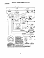
• Check wiring. See electrical widng diagram in the Repair Parts section.
TO REPLACE FUSE
Replace with 30 amp automotive-type plugin fuse. The fuse holder is located behind the
dash.
26
TO ADJUSTCARBURETOR
ACCELERATION
The carburetor has been preset at the factory and adjustment should not be necessary. However, minor adjustment may be
required to compensate for differences in
fuel, temperature, altitude or load. If the
carburetor does need adjustment, proceed
as follows:
• Move throttl_ control lever from slow to
fast position. If engine hesitates or_dies,
tum idle fuel adjusting needle out (counterclockwise) 118 turn. Repeat test and
continue to adjust, if necessary, until
engine accelerates smoothly.
High speed stop is factory adjusted. Do
not adjust - damage may result.
IMPORTANT: Never tamper with the
engine governor, which is factory set for
proper engine speed. Overspeeding the
engine above the factory high speed set-
In general, turning the adjusting needles in
(clockwise) decreases the supply of fuel to
the engine giving a leaner fuel/air mixture.
Turning the adjusting needles out
(counterclockwise) increases the supply of
fuel to the engine giving a richer fuel/air
mixture.
TEST -
ting can be_ng_rous.
If you think the
engine-gov_Tne"_-high speed needs
IMPORTANT:
Damage to the needles and
the seats in carburetor may result if needle is turned in too tight.
NOTE: The carburetor on this engine is
low emission. It is equipped with an idle
fuel adjusting needle with a limiter cap,
which allows some adjustment within the
limits allowed by the cap. Do not attempt
to remove the limiter cap. The limiter cap
cannot be removed without breaking the
adjusting needle.
• Be sure you have a clean air filter and
the throttle control cable is adjusted
properly (see above).
• Stad engine and allow to warm for five
minutes. Make adjustments with engine
running and shift/motion control lever in
neutral (N) position.
• Idle speed setting - With throttle control
lever in slow position, engine should
idle at 1750 RPM. If engine idles too
slow or fast, tum idle speed adjusting
screw in or out until correct idle is attained.
adjusting, contact your nearestAUTHORIZED service center/department, which
has proper equipment and experience to
make any necessary adjustments.
Cable Clamp
Screw
Speed Control Bracket
Throttle Lever
Idle Speed
Adjusting
Screw
Idle Fuel
Adjusting
Needle
• Idle fuel needle setting - With throttle
control lever in slow position, turn idle
fuel adjustment needle in (clockwise)
until engine begins to die and then tum
out (counterclockwise) until engine runs
rough. Turn needle to a point midway
between those two positions.
• Recheck idle speed. Readjust if necessary.
27
Immediately prepare your tractor for storage at the end of the season or if the tractor will not be used for 30 days or more.
_CAUTION:
Never store the tractor with
gasoline in the tank inside a building
where fumes may reach an open flame or
spark. Allow the engine to cool before
storing in any enclosure.
blended fuels (called gasohol or using ethanol or methanol) can attract moisture
which leads to separation and formation of
acids during storage. Acidic gas can damage the fuel system of an engine while in
storage.
• Drain the fuel tank.
• Start the engine end let it run until the
fuel lines and carburetor are empty.
• Never use engine or carburetor cleaner
products in the fuel tank or permanent
damage ro_iLo_u r.
• Use fresh fuel next season.
TRACTOR
Remove mower from tractor for winter
storage. This will allow you to clean it thoroughly. Remove all dirt, grease, leaves,
etc. Store in a clean, dry area.
• Clean entire tractor (See =CLEANING"
in the Maintenance section of this man-
NOTE: Fuel stabilizer is an acceptable
alternative in minimizing the formation of
fuel gum deposits during storage. Add stabilizer to gasoline in fuel tank or storage
container. Always follow the mix ratio
found on stabilizer container. Run engine
at least 10 minutes after adding stabilizer
to allow the stabilizer to reach the carburetor. Do not drain the gas tank and carburetor if using fuel stabilizer.
ual).
• Inspect and replace belts, if necessary
(See belt replacement instructions in the
Service and Adjustments section of this
manual).
• Lubricate as shown in the Maintenance
section of this manual.
• Be sure that all nuts, bolts and screws
are securely fastened. Inspect moving
parts for damage, breakage and wear.
Replace if necessary.
• Touch up all rusted or chipped paint surfaces; sand lightly before painting.
BATTERY
ENGINE
CYLINDER(S)
• Remove spark plug(s).
• Pour one ounce of oil through spark
plug hole(s) into cylinder(s).
• Turn ignition key to "STAR'I-" position for
a few seconds to distribute oil.
• Fully charge the battery for storage.
• After a period of time in storage, battery
may require recharging.
• To help prevent corrosion and power
leakage during long periods of storage,
battery cables should be disconnected
and battery cleaned thoroughly (see
=TO CLEAN BATI'ERYAND
TERMINALS" in the Maintenance section of
• Replace with new spark plug(s).
OTHER
• Do not store gasoline from one season
to another.
this manual).
• After cleaning, leave cables disconnected and place cables where they cannot
come in contact with battery terminals.
• If battery is removed from tractor for
storage, do not store battery directly on
concrete or damp surfaces.
• Replace your gasoline can if it steds to
rust. Rust and/or dirt in your gasoline
will cause problems.
• If possible, store your tractor indoors
and cover it to give protection from dust
and dirt.
ENGINE
FUEL SYSTEM
IMPORTANT:
It is important to prevent
gum deposits from forming in essential
fuel system parts such as carburetor, fuel
filter, fuel hose, or tank during storage.
Also, experience indicates that alcohol
OIL
Drain oil (with engine warm) and replace
with clean engine oil. (See =ENGINE" in
the Maintenance section of this manual).
_
28
• Cover your tractor with a suitable protective cover that does not retain moisture. Do not use plastic. Plastic cannot
breathe, which allows condensation to
form and cause your tractor to rust.
IMPORTANT:
Never cover tractor While
engine and exhaust areas are still warm.
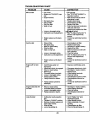
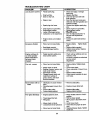
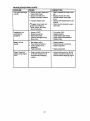
TROUBLESHOOTING
CHART
CAUSE:
PROBLEM
Willnctstad
CORRECTION
• Out of fuel.
• Engine not "CHOKED" propedy.
• Engine flooded.
•
•
•
•
Bad spark plug.
Dirty air filter,
Dirty fuel filter.
Water in fuel.
• Loose or damaged widng.
• Carburetor out of adjustment.
• Engine valves out of adjustment.
Hard to start
•
•
•
•
•
Dirty air filter,
Bad spark plug.
Weak or dead battery.
Dirty fuel filter.
Stale or dirty fuel.
• Loose or damaged wiring.
• Carburetor out of adjustment.
• Engine valves out of adjustment.
Engine will not turn
over
• Clutch/brake pedal not
depressed.
• Attachment clutch is engaged.
• Weak or dead battery.
• Blown fuse.
• Corroded battery terminals.
• Loose or damaged widng.
• Faulty ignitionswitch.
• Faulty solenoid or starter.
• Fill fuel tank.
• See "TO START ENGINE" in
Operation section.
• Wait several minutes before
attempting to start.
• Replace spark plug.
• Clean/replace air filter.
• Replace fuel filter.
• Drain fuel tank and carburetor,
refill tank with fresh
gasoline and replace fuel filter.
*_h_
all widng.
• See "To Adjust Carburetor"in
Service and Adjustments
section.
• Contact an authodzed service
center.
•
•
•
•
•
Clean/replace air tilter.
Replace spark plug.
Recharge or replace battery.
Replace fuel filter.
Drain fuel tank and refill with
fresh gasoline.
• Check all widng.
• See =ToAdjust Carburetor" in
Service and Adjustments
section.
• Contact an authorized service
center.
• Depress clutch/brake pedal.
• Faulty operator presence
switch(as).
Disengage attachment clutch.
Recharge or replace battery.
Replace fuse.
Clean battery terminals.
Check all widng.
Check/replace ignition switch.
Check/replace solenoid or
starter.
• Contact an authorized service
center.
Engine dicks but will
not start
•
•
•
•
•
•
•
•
Loss of power
• Cuffing too much grass/too
fast.
• Throttle in =CHOKE" position.
• Build-upof grass, leaves and
trash under mower.
• Dirty air filtar.
• Low oil leveUcrtrtyoil.
Weak or dead battery.
Corroded battery terminals.
Loose or damaged widng.
Faulty solenoid or starter.
29
•
•
•
•
•
•
•
Recharge or replace battery.
Clean battery terminals.
Check all widng.
Check/replace solenoid or
starter.
• Set in "Higher Cut" position/reduce speed.
• Adjust throttle control.
• Clean underside of mower
housing.
• Clean/replace air tilter.
• Check oil leval/change oil.
TROUBLESHOOTING
CHART
PROBLEM
CAUSE
CORRECTION
Loss of power (cont'd)
• Faulty spark plug.
• Clean and regap or change
spark plug.
• Replace fuel tilter.
• Drain fuel tank and refill with
fresh gasoline.
• Drain fuel tank and carburetor,
refilltank with fresh gasoline and
replace fuel tilter.
• Connect and tighten spark plug
wire.
• Clean engine air screen/fins.
• Clean/replace muffler.
• _=leck'_ll wiring.
• See =ToAdjust Carburetor" in
Service and Adjustments section.
• Contact an authorized service
center.
• Dirty fuel tilter.
• Stale or dirty fuel.
• Water in fuel.
• Spark plug wire loose.
•
•
•
•
Dirty engine air screen/tins.
Dirty/clogged muffler.
Loose or damaged wiring.
Carburetor out of adjustment.
• Engine valves out of adjustment.
Excessive vibration
• Worn, bent or loose blade.
• Bent blade mandrel.
• Loose/damaged part(s).
Engine continues to
run when operator
leaves seat with at
tachment clutch
engaged
• Faulty operator-safety presence control system.
Poorcut-uneven
• Worn, bent or loose blade.
• Mower deck not level.
• Buildup of grass, leaves, and
trash under mower.
• Bent blade mandrel.
• Clogged mower deck vent
holes from buildup of
grass, leaves, and trash
around mandrels.
Mower blades will not
rotate
Poor grass discharge
• Replace blade. Tighten blade
bolt.
• Replace blade mandrel.
• Tighten loose part(s). Replace
damaged pads.
Check wiring, switches and connections. If not
corrected, contact an authorized
service center/
department.
• Replace blade. Tighten blade
bolt.
• Level mower deck.
• Clean underside of mower housing.
• Replace blade mandrel.
• Clean around mandrels to open
vent holes.
• Obstruction in clutch mechanism.
• Worn/damaged mower drive
belt.
• Frozen idler pulley.
• Frozen blade mandrel.
• Remove obstruction.
• Engine speed too slow.
• Place throttle controlin "FAST"
position.
• Shift to slower speed.
• Allow grass to dry before mowing.
• Level mower deck.
• Check tires for proper air pressure.
• Replace/sharpen blade. Tighten
blade bolt.
• Travel speed too fast.
• Wet grass.
• Mower deck not level.
• Low/uneven tire air pressure.
• Worn, bent or loose blade.
30
• Replace mower drive belt.
• Replace idler pulley.
• Replace blade mandrel.
TROUBLESHOOTING
PROBLEM
CHART
CAUSE
CORRECTION
i
Poor grass discharge
(cont'd)
• Buildup of grass, leaves and
trash under mower.
• Mower drive belt worn.
• Blades improperly installed,
• Improper blades used.
• Clogged mower deck vent
_holes from buildup of
grass, leaves, and trash
around mandrels.
Headlight(s) not
working (if so
equipped)
•
•
•
•
•
Battery will not
charge
• Bad battery cell(s).
• Poor cable connections.
• Faulty regulator (if so
equipped).
• Faulty alternator.
• Replace battery.
• Check/clean all connections.
• Replace regulator.
• Engine throttle control not set
at "SLOW" position for 30
seconds before stopping
engine.
• Move throttle control to "SLOW"
position and allow to idle for 30
seconds before stopping engine.
Engine "backfires"
when turning engine
"OFF"
Switch is "OFF".
Bulb(s) burned out.
Faulty light switch.
Loose or damaged wiring.
Blown fuse.
i
• Clean underside of mower housing.
• Replace mower drive belt.
• Reinstall blades sharp edge
down.
• Replace with blades listed in this
manual.
• Clean around mandrels to open
vent holes.
31
•
•
•
•
•
Turn switch "ON".
Replace bulb(s).
Check/replace light switch.
Check wiringand connections.
Replace fuse.
• Replace alternator.
32
TRACTOR
-- MODEL
NUMBER
917.271012
SCHEMATIC
REO
I
AMMETER
I
ATT'MENTCLUTCH
i _
i
t
(CLUTCH OFF)
I
i 85
(NOT OCCUPIED)
SEAT SWITCH
R
86 _
_87
i8"
_l
_
,
i
87A
'
.......
FUEL SHUT-OFF
SOLENOID
301
i
T
I
PRESENCERELAY#1
'sz
:
j__85
3o,
86 i
SPARK
-d_f&-'
UNIT
IGNITION
CHARGING
I
J
_
v
GAP
2 PLUGS
PLUG ON
TW N CYL ENGINES
_) VOLT8 AC MIN. I 3100 RpM
(CH/*RGINQ Sy_;TEM _4SCONNEC31EO}
SYSTEM OUI_UT
DIODE
i ALTERNATOR II
I
LIGit11NG SY
OUTPUT
| AMP AC • _
NOTE
i
.........
t4 VOLTS AC MIN. I 3600 RFM _1_8
OFF)
]
YOUR TRACTOR IS
EQUIPPED WITH A SPECIAL
THE LIGHTS ARE NOT
CONNECTED TO THE
BATTERY,
BUTSYSTEM.
HAVE THEIR
ALTERNATOR
OWN ELECTRICAL SOURCE.
IGNFRON SWITCH
RI=M _*
"_
_j_
,,,
HEADLIGHTS
BECAUSE OF THIS, THE
RELAY
BRIGHTNESS OF THE LIGHTS
WILL CHANGE WITH ENGINE
SPEED. AT IDLETHE LIGHTS
_
WILL DIM. AS THE ENGINE IS
NON-REMOVABLE
SPEEDED UP, THE LIGHTS
WILL BECOME THEIR BRIGHTEST, CONNECTIONS
F"/
REMOVABLE
CONNECTIONS
WIRING INSULATED CLIPS
NOTE: IF WIRING INSULATED CLIPS WERE REMOVED FOR
SERVICING OF UNIT, THEY SHOULD BE REPLACED TO
PROPERLY SECURE YOUR WIRING.
33
l_J
TRACTOR
-- MODEL
NUMBER
917.271012
ELECTRICAL
--
.....
22
......
21
25
/
/
//
34
TRACTOR
- - MODEL
NUMBER
917.271012
ELECTRICAL
KE_
PART
NO._ NO.
1
2
8
16
19
20
21
22
24
25
26
27
28
29
30
31
32
33
40
41
42
43
44
45
52
70
81
163465
74760412
156417
161343
STD551125
73350400
147430
4152J
4799J
146147
108824X
73510400
4207J
160784
140301
124211X
141226
109310)(
161352
71110408
131563
145673
73640400
121433X
141940
142621
109748X
DESCRIPTION
Battery,12Volt 28 Amp
Bolt, Hex 1/4-20 x 3/4
Case, BatteryMech Hinge
Switch, Intadock N. OPN.!N.OPN
Washer, Lock 1/4
Nut, Hex, Jam 1/4-20 UNC
Harness, LightSocket(w/4152J)
LightBulb
Cable, Battery,6 Gauge, Red, 11"
Cable, Battery, 6 Gauge, Red, W16 Wire
Fuse, 30 Amp
Nut Keps Hex 1/4-20 UNC
Cable, Ground, 6 Gauge, Black, 12"
Switch, Plunger NormalOP Olive
Switch, Ignition4 Position
Nut, Ignition
Cover, IgnitionSwitch
Key, Molded,Craftsman
Hamess, Ignition
BoltBIk Fin Hex 1/4-20 UNC x 1/2
Cover, Terminal
Solenoid
Nut,Keps BIk Hex 1/4-20 UNC
Ammeter, Rectangular15 Amp
ProteCtionWire Loop(Hour Meter)
Harness, Engine Kohl Cmd-L 15AR
Relay Asm.
NOTE: Allcomponent dimensionsgiven in U.S. inches
1 inch= 25.4 mm
35
TRACTOR - - MODEL
CHASSIS AND ENCLOSURES
NUMBER
917.271012
53
57
54
,_3
14
74
36
TRACTOR
- - MODEL
NUMBER
917.271012
CHASSIS AND ENCLOSURES
KEY
PART
NO.
NO.
DESCRIPTION
1
160392
ChassisAssembly
2
3
140356
17490612
4
5
9
19131216
155272
161917)(013
10
11
STD533710
155927
12
13
14
145660
155934X010
17490608
17
18
144983X558
126938X
25
26
28
19131312
STD541437
145198)(558
29
30
31
155217X599
151287)(558
139976
37
38
39
51
17490508
139886
139887
73800400
52
53
54
19091416
145201
161464
55
57
58
145202
STD552507
150127
60
64
74
140
STD533707
154798
$TD541437
158418
142
143
144
165867
154966
154207
145
--
156524
5479J
Drawhar
Screw, Thd., Roll. 3/8-16 x 3/4
Washer 13/32 x 3/4 x 16 Gauge
BumperHood/Dash
Dash
Bolt,Carriage 3/8-16 x 3/4
Panel, Dash, LH
Clip Tinnerman Grille Prt.
Panel, Dash, RH
Screw, Thd., Roll. 3/8-16 x 1/2
Hood Assembly
Bumber Hood
Washer 13/32 x 13/16 x 12 Gauge
Locknut
Grille w/Clips MS-558
Lens, Grille
Fender/Footrest Pnt STLT N Hold 558
Bracket, Fender/Support
ScrewThdrol 5/16-18 x I/2
Pivot BracketAssembly,LH,
Pivot BracketAssembly,RH,
Nut Lockw/Insert 1/4 - 20 UNC
Washer, 9/32 x 7/8 x 16 Gauge
Bracket, Gdlle PickoffLH
Screw, Hex Wshd #5-19 x 7/8
Bracket,Gdlle PickoffRH
Bo_t,FinHex 1/4 -20 UNC x .75
Duct,Air Engine PL/LT
Bolt, Rdnd Sqnk 3/8-16 UNC x 3/4
Dash, LowerSTLT
Nut, Crown_?,k3/0-16 UNC
Bracket, SuspensionFront
Plate, ReinforcementSTLT
Bracket, Swayhar Chassis
Bracket, FootrestSTLT
Rod Pivot Chaesi_Hood
Plug, Button
NOTE: -,_JIc_tmponentdimensionsgiven in U.S. inches
1 inch = 25.4 mm
37
TRACTOR
- - MODEL
NUMBER
GROUND DRIVE
38
917,271012
TRACTOR
- - MODEL
NUMBER
917.271012
GROUND DRIVE
KEY
NO.
1
PART
NO.
....
2
3
4
5
6
8
10
11
13
14
15
18
146662
123666X
12000028
t21520X
17490512
154792
STD561210
105701X
74550412
STD551125
74490544
STD523710
19
21
22
24
25
26
27
26
29
30
31
32
34
35
36
37
38
39
40
41
42
47
48
49
50
51
52
STD541437
106933X
130804
STD541237
106888X
STD551037
STD561210
145204
124236X
130807
127275X
STD523107
155071
120183X
STD551062
STD571810
131494
STD523727
4470,.I
165838
19131312
127783
154407
123205X
STD523715
STD541437
STD541431
DESCRIPTION
KEY
NO.
Traneaxle(Ses Breakdown)
Dana, Model Number4360-122
Bprir_, Retum, Brake
Pulley,Traneaxls
Ring_Retainer
Stra_,Torque
Screw,Thd.,Roll. 5/16-18x3/4
Rod Shifter Fender STLT
Pin, Cotter
Washer, Shift Plate
Bolt 1/4-28 UNF W/Patch Gr. 8
Washer
Bolt, Hex Flghd 5/16o16Gr. 5
Bolt Fin Hex 3/8-16 UNC x 1.
Gr. 5
Nut
Knob
Rod, Brake
Nut
Spring,Brake Rod
Washer
Pin
Rod, ParkingBrake
Cap, ParkingBrake, Red
Bracket, Transaxle
Keeper, Belt, L.H.
Bolt
ShaftAssembly, Foot Pedal
Bearing, Nylon
Washer
Roll Pin
Pulley,Idler, Flat
Bolt
Spacer, Split .395 x .59
Keeper, Belt, Idler
Washer 13/32 x 13/16 x 12 Ga.
Pulley, Idler, V-Groove, Plastic
BellcrsnkClutch Grnd Dr,, Stl
Retainer, Belt
Bolt
Nut Crown Lock 3/8-16 UNC
Nut Crown Lock 5/16-18 UNC
PART
NO.
53
55
56
57
58
59
61
62
63
64
105710X
105709X
STD523712
160855
127274X
140312
17490612
8883R
140186
71170764
65
66
STD551143
154778
70
72
74
75
76
77
78
80
81
82
83
84
85
86
87
88
89
90
134683
19132012
109502X
121749X
STD581075
123583)(
121748)(
160783
161077
123782X
19171216
145643
150360
157480
19212016
12000008
158391X428
124346X
112
116
148
149
150
151
19091210
72110610
159103
122052X
150935
19133210
DESCRIPTION
Link,Clutch
Spring,Clutch Return
Bolt Fin Hex 3/8-16 x 1-1/4
V-Belt, GroundDrive
Keeper,Belt, R.H.
Keeper, Belt, CenterSpan
Screw,Thd.,Roll. 3/8-16x3/4
Cover, Pedal
Pulley,Engine
Bolt,HexHead, Fin.
7/16-20 x 4 Gr. 5
Washer
Keeper, Belt, Engine, FoolProof
Guide, Mower Drive Belt,R.H.
Washer 13/32x 1ol/4x 12 Ga.
Spacer, Split
Washer 25/32 x 1-1/4 x 16 Ga.
E-Ring
Key, Square 2.0 x .1845/.1865
Washer 25/32 x 1°5/8x 16 G.
Arm, Shift
BhaftAssembly
Spdng, Torsion
Washer 17i32x3/4x16Ga.
Tie Rod
Nut, Nylock
Bushing,Pivot
Washer
E-Ring
Console, Shift, STLT
Nut, Self-Threading,Washer Hd
1/4
Washer 9/32 x 3/4 x 10 Ga.
Bolt RdhclBqneck 3/8-16 x 1.25
Spacer
Spacer Retainer PM Mower
BushingNylonCollered
Washer 13/32 x 2 x 10 Ga.
NOTE: Allcomponentdimensionsgiven in U.S, inches
1 inch = 25.4 mm
39
TRACTOR
- - MODEL NUMBER
917.271012
STEERING ASSEMBLY
36
63
L
67
47
43
4O
TRACTOR
- - MODEL NUMBER
917.271012
STEERING ASSEMBLY
KEY
NO.
PART
NO.
1 139768
2 154427
3 156483
4
157473
5 6266H
6 121748X
7 19272016
8 12000029
9 3366R
10
156438
11 STD551137
13 154779
15 73901000
17
156546
18 57079
19
124035X
20
126684X
22
71200410
23
127501
25
154406
26
126847X
27
136874
28
19131416
29
17490612
30 STD561210
32
130465
36
155099
37
152927
38
139769
39
19133808
40 STD541537
41
100711L
42
145054
43
121749X
44
153720
46
121232X
47 6855M
51 STD541431
54 74780520
62
156594
63
STD523710
65 ÷,,,,'t
_
66
154404
67
74781044
68
154429
DESCRIPTION
Wheel, Steadng
AxJe,Asm Front
Spindle,Asm Lh
Spindle,Asm Rh
Beadng, Race ThrustHarden
Washer, 25/32 x I 5/8 x 16ga
Washer, 27/32 x I 1/4 x 16 Ga
Ring, Klip#t5304-75
Bearing, Col Strg BIk
Draglink,Extended Stamped
Washer, Lock Hvy Hlcl Spr 3/8
Beadng,Axle STLT/GT
Locknut' Flange 5/8-11 UNC
Shaft,Asm Strg PrivateLabel
Washer, Thrust 515 x 750 x 033
Support,Shaft
Washer,Shim 1/4 x 5/8 x 062
Screw,Hex SocketHd 1/4-20 x 5/8
Shaft,Asm Pittman
Bracket, Steedng
Bushing,Rod Tie BIkLt
Gear, Sector
Washer, 13/32 x 7/8 x 16ga
Screw, Thdrol3/8-16x3/4 Ty-tt
Pin, Cotter 1/8 x 3/4 Cad
Rod, _e Wire Form 19 75 Mech
Bushing,Strg 5/8 Id Dash
Screw, "IF #10-32 x 5 x 3/8 Flange
Insert, Staering Wheel
Washer, 13/32 x 2-3/8 x 8 Gauge
Lock Center Nut 3/8-24 Unf
Adaptor,Wheal Strg
BootShaft Steering
Washer, 25/32 x 1-1/4 x 16 Gauge
Extension,Steedng Non-Adjust
Cap, Spindle FrTop BIk
Fitting,Grease
Nut Lock Hex wilas 5/16 -18 UNC
BoltFin Hex 5/16 - 18 UNC x t -1/4
Kit, Staedng Assembly
Bolt,Fin Hex 3/8-16 UNC x 1 Gr. 6
Spacer, Axle
Beadng,Ann Pittman
Bolt,Fin Hex 5/8-11 UNC x 2-3/4
Axle, Brace
NOTE: All componentdimensionsgiven in U.S. inches
1 inch= 25A mm
41
TRACTOR
- - MODEL
NUMBER
917.271012
ENGINE
80
4
6
33
29
40
23
/
OPTIONAL
EQUIPMENT
Spark Arrester
w
42
TRACTOR
- - MODEL NUMBER
917.271012
ENGINE
KEY
NO.
PART
NO.
1
2
162156
17720410
3
.......
4
13
14
15
16
23
29
31
32
33
35
37
159420
12-041-03
13280328
13200300
STD551231
159880
137160
109202X
158990
123487X
17490512
137040
3 8
.......
40
44
46
62
77
79
80
81
101
124028X
17490412
19091416
STD551131
19101216
M740108025
74760508
128861
M73030800
DESCRIPTION
Control, Throt/ Ch
Screw, Hex Thd Cut 1/4-26x5/8 T
Engine(See Breakdown)KohlerModel No. CV15S-41564
Muffler
Gasket KohlerCV-CV16.5
Nipple, Pipe 3/8 NPTx 3-1/2
Elbow,Std 90 Degree 3/8-18 Npt
Washer
Shield,BRN/DBR Guard
Arrestor,Spark
Tank, Fuel
Cap Assembly, Fuel Tank, Vented
Clamp, Hose BIk
Screw, Thdrol 5/16-16 x 3/4 TYT
Line Fuel
PlugO_1Drain (Order From Engine Manufacturer)
Bushing,Snap, Fuel Line
Screw, Hex Washer Head, Thd. Rell. 1/4-20 x 3/4
Washer, 9/32 x 7/8 x 16 Gauge
Washer, Lock
Washer 5/16 x 3/4 x 16 Gauge
Bolt,Hex
Bolt, Hex Hd 5/16-18 UNC x 1/2
Nut, Flange 1/4-20 Starter Nut
Nut Flange M8-1.25 Non-LkZinc
NOTE: All componentdimensionsgiven in U.S. inches
1 inch= 25.4 mm
43
TRACTOR--
MODEL
NUMBER
917.271012
SEAT ASSEMBLY
21
KEY
NO.
1
2
3
4
5
6
7
8
9
10
11
12
PART
NO.
DESCRIPTION
140123
140551
STD523710
19131610
145006
STD541437
124181X
17490516
19131614
155925
120068X
121246X
o
Sea_, _
Bracket, Pivot, Seat
Bolt
Washer 13/32 x 1 x 10 Gauge
Clip, Push-In Hinged
Nut
Spring, Seat
Screw, Thd.,Rolt. 3/8-16xl
Washer 13/32 x I x 14 Gauge
Pan, Seat EmbossQCK Conn.
Knob Seat 1/2-13 UNC BIk
Bracket, Switch Mounting
KEY
NO.
13
14
15
16
17
21
22
24
PART
NO.
121248X
72050412
134300
121250X
123976X
153236
STD541431
19171912
DESCRIPTION
Bushing,Snap
Bolt,Cawiage 1/4-20 x 1-1/2
Spacer,Split .28 x +88
Spring
Locknut,Flange 1/4 Grade 5
Bolt, Shoulder 5/16-18 UNC
Nut
Washer 17/32 x 1-3/16 x 12
Gauge
Bolt, Shoulder 5/16-18 x ,62
25 127018X
NOTE: Allcomponent dimensionsgiven in U.S. inches
1 inch= 25.4 mm
44
TRACTOR
- - MODEL
NUMBER
917.271012
DECALS
5
6
4
3
10
13
2O
12
KEY
NO.
PART
NO.
1
3
4
5
156368
163200
163202
163261
6
8
9
10
12
133644
163203
163204
156439
146046
KEY
NO.
DESCRIPTION
Decal, Oper. Instr.
Decal, Hood, R.H.
Decal, Hood, L.H.
Decal, Dash Pnl Kohler 15.5
OHV
Decal, CustomerMaintenanca
Decal, Deck Mower F_Z3
Decal, Fender, Craftsman
Decal, Fender Danger
Decal, V-Belt Drive Schematic
WHEELS & TIRES
2_
13
163207
14
20
21
------
160396
149516
138047
138311
154515
154516
167098
167099
KEY
NO.
I
2
3
4
5,8
4,10
11
PART
NO.
PART
NO.
59192
65139
106222X
599o4
5
6
106732X427
278H
7
9040H
8
9
10
I06108X427
122082X
7152J
11
--
I04757X
144334
DESCRIPTION
Decal, Fend Sd Wht Radi6sp
42
Decal, V-Belt Schematic
Decal Battery DngdPsn Eng
Decal, BatteryDiehard Sears
Decal, LiftHandle
Pad FootrestLH STLT
Pad Footrest RH STLT
Owner'sManual, English
Owner'sManual, Spanish
DESCRIPTION
Valve Cap, "Rre
Stem, Valve
_re, Front
Tube, Front"13re
(Not Provided,Service Item
Only)
Rim, Front
Fitting,Grease (Front Wheel
Only)
Bearing, Flange (FrontWheel
O_)
Rim, Rear
"Rre,Rear
Tube, Rear _re
(Not Provided,ServiceItem
Only)
Cap, Axle
Sealant, "[lie 10 oz.
NOTE: Allcomponentdimensionsgiven in U.S. inches
1 inch= 25.4 mm
45
TRACTOR
- - MODEL NUMBER
917.271012
LIFT ASSEMBLY
3
13
2
6
13
19
20
13
20
15
46
TRACTOR
- - MODEL
NUMBER
917.271012
LIFT ASSEMBLY
KEY
NO.
1
2
3
4
5
6
7
8
11
12
13
15
16
17
18
19
20
31
32
PART
NO.
DESCRIPTION
159460
159471
105767X
12000002
19211621
120183X
125631X
122365X
139865
139866
STD624008
127218
73350800
130171
73680800
139868
163552
140302
73540600
Wire Asm Inner/Sprgw/PlungerLT
ShaftAsm. Lift
Pin Groove
E Ring #5133-62
Washer 21/32 x 1 x 21 Ga.
Beadng Nylon
Grip Handle Ruted
ButtonPlungerRed
LinkLiftLh Fixed Length
LinkLiftRh Fixed Length
Retainer Spring
LinkFront
NutJamHex 1/2-13Unc
TrunnionBIkZinc
Nut Crownlock1/2-13 Unc
Arm, SuspensionRear
Retainer Spring
Bearing, Pivot,LiftSpherical
Nut, Crownlock 3/8-24
NOTE: All componentdimensionsgiven in U.S. inches
1 inch = 25.4 mm
47
TRACTOR
- - MODEL
NUMBER
917.271012
MOWER DECK
34
32
58
_-21
116
113 111
114
\
16
29
,18
5
6
J
21
48
27
TRACTOR
- - MODEL NUMBER
917.271012
MOWER DECK
KEY
NO.
PART
NO.
1
2
3
164961
STD533107
138017
4
5
6
8
9
10
11
12
13
138440
STD624008
130832
850857
STD551137
140296
134149
129895
137645
14 128774
15 110485X
16 140329
17 72110610
18 STD533106
19 132827
20
159770
21 STD541431
22
134753
23
131267
24
I05304X
25
123713X
26
110452X
27
130968
28
19111016
29
131491
30
157722
31
129963
32
153535
33
137266
34
STD533717
35
133835
36
131494
37 STD551037
40
STD541437
41
133551
43
140083
44 _ 140088
45
STD624003
46
137729
48
133944
49
155066
50
131340
51 STD541410
52
139888
53
131845
54
133943
55
15.5046
56
122052X
58
140086
KEY
NO.
DESCRIPTION
Mower Housing
Bolt
BracketAssembly,Swey Bar,
Front
BracketAssembly,Sway Bar
Retainer Spring
Arm, Suspension,Rear
Bolt,Hex 3/8-24 x 1.25 Gr. 8
Washer, Lock
Washer, Hardened
Blade, Mulching
Beadng, Ball
ShaftAssembly,Mandrel,
Vented (IncludesKey No. 6)
Housing,Mandrel, Vented
Beadng, Ball, Mandrel
Stripper,VentedMower Deck
Bolt, Carriage 3/8-16 x 1-1/4
Bolt, Carriage 5/16-18x5/8
Bolt, Shoulder
Baffle,Vortex
NutCmwnlockS/16-18UNC
StiffenerBracket
Bracket, Deflector
Cap, Sleeve
Spring,Torsion,Deflector
Nut, Push
Shield, Deflector
Washer 11/32x5/8x16Ga.
Rod, Hinge
ScrewThdrolWasherHead
Washer, Spacer
Pulley, Mandrel
Nut, Toplock,Flanged
Bolt
Fastner, ChdstrnasTree
Pulley, Idler,Rat
Washer 13i32x13/16x16Ga.
NutCrownlock3/8-16UNC
Rod, Pivot,with Nibs
Rod, Clutch, Secondary,w/Nibs
Guard, Mandrel, LH.
Retainer
Screw, Thd. Roll 1/4-20 x 5/8
Wasl_r, H_rdened
RollerAssembly,Cam Follower
Bolt, Shoulder #10-24 Grade 5
Locknut
Bolt, Shoulder 5/16-18 UNC
ArmAseembly,Pad, Brake
Washer, Hardened
Arm, Idler
Spacer, Retainer
Spring,TorsionBrakes
PART
NO.
59
67
68
71
72
73
74
75
76
141043
162113
144200
142427
131870
127847
121748X
12000029
128903
77
78
127845
160570
79
80
81
82
83
84
85
92
101
102
103
104
105
106
111
112
113
114
115
116
117
118
119
121
128
129
130
127498
153701
STD541237
142028
120958X
156084
72140620
STD541437
136420
71161010
19061216
STD551110
160793
2029J
155197
155198
17490512
STD541431
72110504
137644
133957
73930600
STD551037
143723
153390
19131312
STD523710
131
STD533710
132
19132203
141
--
6266H
130794
--
164963
DESCRIPTION
Guard, TUV Idler
Kneb Custom Oval
V-Belt
ROd, Clutch, Pdmary,with Nibs
Spring, Retum
Arm, Clutch, Secondary
Washer 25/32 x 1-5/8 x 16 Ga.
Ring, Klip
Bolt, Shoulder 3/8-16 UNC x
1.44
Keeper, Spring
Lever Asm. Clutch Pd PIm
STLT
Bushing,Large, Brass
Spring, Mower Clutch
Nut, HexJam 3/8-16 Unc
Trunnion,Adj.
Washer Sintered
Keeper Belt Idler
Bolt Carriage3/8-16 x 2-1/2 G 5
Nut
MulcherCover
Screw
Washer #10
Washer, Lock
LatchAssembly,Bagger
Nut, Weld
Bracket, Gauge, Wheel L.H.
Bracket, Gauge, Wheel R.H.
Screw Thdrol 5/16-18 x 3/4
Nut, Hex, Keps 5/16,18 UNC
Bolt, Carriage 5/16 UNC x 1/2
Bolt,Shoulder
Wheel, Gauge
Nut, Centedock3/8-16
Washer 3/8 x 7/8 x 14 Gauge
Bracket
Washer Felt
Washer 13/32 x 13/16 x 12 Ga.
Bolt, Fin Hex 3/8-16 UNC x 1
Gr. 5
Bolt, RDHD SQNK 3/8-16 UNC
xl
Spacer, Washer 13/32 !.D. x 13/80.D. x 1/4
Washer Thrust .75 x 1.230
Mandrel Assembly(Includes
Key Numbers 6,10, 12-15, 31
and 32)
Mower Deck,Complete
(Standard Deck, Order
Separately Mulcher Plate and
Gauge Wheel Components,
Key Nos. 101-106 and 111-121)
NOTE: Ag componentdimensionsgiven in U.S.inches
1 inch= 25.4 mm
49
TRACTOR
- - MODEL NUMBER
917.271012
DANA TRANSAXLE - - MODEL NUMBER 4360-122
20
21
22
24
25
31
27
33
36
38
53
46
12
47
48
49
50
59
62
63
67
70
so
TRACTOR
- - MODEL
NUMBER
917.271012
DANA TRANSAXLE - - MODEL NUMBER 4360-122
KEY
PART
NO.
NO.
DESCRIPTION
KEY
PART
NO.
NO.
DESCRIPTION
1
2
3
4
5
160955
2274J
134400
105904X
160940
6
7
8
9
10
11
12
13
134788
108727X
120951X
148266
2225,1
134793
143697
120415X
14
15
16
17
18
19
20
21
22
23
24
25
26
27
28
29
30
31
32
33
34
35
142674
161563
161564
105909X
105910X
148269
160943
138246
138238
148268
143673
2244J
105916X
120470X
110070X
142677
142681
124644X
108980X
120406X
134796
t05925X
Housing,Upper
Screw, Tapping,1/4-20 X .734
Bell, Detent
Spring,Detent
Screw,Tapping,No. 10-24 X
.482
Assy,Kit, Shifter
V-Ring
Puck, Fnction
Bearing, Flange
Ring, Retaining
Assy,Kit, Shim, .625 Shaft
Gear, Spur, 15T
Washer, Plain, .632 X 1.38 X
.046
Key, Woodruff,No. 9
Assy,Kit, InputShaft
Pinion, Bevel, 12T
Ring, Retaining
Chain,24 Pitches
Seal, Oil
Gear, Spur,12T
Collar,Clutch
Assy,Kit, Clutch Keys
Beadng, Flange
Shaft, Intermediate
Key, Woodruff,No. 61
Ring, Retaining
Sprocket, 18T
Spacer, 1.131 X 1.45 X .494
Gear, Spur,37T
Gear, Spur, 35T
Gear, Spur,3OT
Gear, Spur,25T
Gear, Spur,22T
Gear, Spur, 19T
Washer, Plain, .640 X 1.37 X
.061
37
2231J
38
39
40
41
42
43
44
45
46
47
48
49
50
51
16(}944
124639X
120472X
105928X
161565
134394
120473X
160942
142678
124641X
106589X
120408X
105937X
2226J
52
53
134401
2264J
54
55
56
57
58
59
60
61
62
63
64
65
66
67
68
69
160946
160947
160948
110071X
120952X
160949
16(7950
160951
120961X
7294J
108989X
160952
120954X
160953
138244
108996X
Washer, Plain, .632 X 1.00 X
.031
Assy, Gear, Comb., 12T & 30T
Shaft, Idler
Spacer, .633 X .87 X .755
Sprocket,9T
Gear, Bevel, 36T
Assy,Kit, Shim, .750 Shaft
Shaft, Drive
Cover, Detent
Gear, Spur, 12T
Gear, Spur,20T
Gear, Spur,25T
Gear, Spur,28T
Gear, Spur, 31T
Washer, Plain, .632 X 1.00 X
.060
Washer, Neoprene
Washer, Plain, .758 X 1.25 X
.031
Axle, LH
Gear, Miter,12T, Spnned
Ring, Retaining
Gear, Spur,32T
Shaft, Cross
Gear, Miter, 12T, Idler
Axle, RH
Housing,Lower
Pock, Friction
Disc, Brake
Spacer, Brake Pock
Jaw, Brake
Pin, Dowel
Screw, Tapping,5/16-18 X 2.35
Lever, Actuating
Washer, Plain, .321 X 1.00 X
.055
Bracket,Anti-Rotation
Nut, Lock, 5/16-24
Grease
70
160954
36
2228J
Washe[;,,Plau_,
.632 X 1.00 X
.046
71
72
73810500
120416X
NOTE: All componentd_mensio_ given io U.S. iochea
1 inch= 25.4 mm
51
TRACTOR
- - MODEL NUMBER
917.271012
KOHLER ENGINE - MODEL NUMBER CV15S, TYPE NUMBER PS-41564
AIR INTAKE
J
;LOWER
HOUSING
AND BAFFLES
Y
1-- 8
I
_r
_6
15
$
_B4
5--e
7_t 6
NGINE
CONTROLS
J
10
CRANKSHAFT
I
--,o ,3_\ i
EXHAUST
-'
I
_1
_i_),_ 4
/
_3
6
52
TRACTOR
- - MODEL NUMBER
917.271012
KOHLER ENGINE - MODEL NUMBER CV15S, TYPE NUMBER PS-41564
AIR INTAKE
KEY
NO.
1
2
3
4
5
6
7
PART
NO.
25-341-02
12-096-24
12-083-08
12-100-01
X-25-63
12-313-04
12-083-05
8
9
12-072-03
12-086-01
ENGINE CONTROLS
KEY
NO.
DESCRIPTION
Knob, Air Cleaner Cover
Cover, Air Cleaner
Precleaner Element
Wing Nut
Washer, Plain 1/4
Grommet
Element, Air Cleaner (Includes
#6)
1012-094-12
11 12-041-02
NOT ILLUSTRATED
- - 12-113-53
Stud, M6X 1.0X75
Screw, #10 Hi-LoThread
Forming
Base, Air Cleaner
(Includes Key Numbers9 and
10)
Gasket, Air Cleaner
PART
NO.
12-014-37
12-139-01
DESCRIPTION
Crankshaft
Plug,Cup
PART
NO.
M-0545010
Baffle, Intake Side
Screw, Hex flangeM6 x 1.0 x
16(2)
14 12-063-08
15 12-06301
NOT lU.USTRATED
- - 12-113-55
M-0545016
5
12-536-09
6
M-0443020
7
SM-0443025
8
9
10
11
12
12-089-11
12-089-23
12-089-24
M-0641060
SM-0642025
13
14
15
16
12-090-05
25-158-11
12-079-01
25-158-08
DESCRIPTION
Linkage,Choke
Clamp, Cable
Screw (2), LockedSocket
Screw,Hex Flange M5 x .8 x 16
Control,Speed Assembly
(includes Key Numbers6
through9)
Screw, Pan Head M4 x 0.7 x
20
Screw, Pan Head M4 x 0,7 x
25
Spdng, ChokeAdjust
Spring, Choke Retain
Spdng, Governor
Nut, Hex Flange M6 x 1.0
Screw, Hex Flange
M6x 1.0x25
Lever, Governor
Bushing,Throttle Linkage
Linkage, Throttle
Bushing, Linkage Retaining
PART
NO.
M-0829033
12-041-03
M-0841080
12-126-11
12-445-06
M-0645025
DESCRIPTION
Stud, M8 x 1.25 x 33 (2)
Gasket, Exhaust Manifold
Nut, Hex Flange M8 x 1.25 (2)
Bracket, Muffler
Strap, Lifting
Screw, Hex Flange
M6 x 1.0 x25 (2)
NOT ILLUSTRATED
- - 12-522-18
- - 12-755-59
Short Block
Gasket Set
RPM Settings:
RPM Settings
Low Speed: 1500-2000
High Speed: 3200-3400
NOTE: All componentdimensionsgiven in U.S. inchea
1 inch= 25A mm
(3)
12-063-05
M-0645016
4
KEY
NO.
1
2
3
4
5
6
DESCRIPTION
Screw, Hex Flange
M5x 0.8 x 10 (13)
2 24-468o10
Washer, Plain 1/4
3 12-146-07
Plate, BlowerHousing
4 M-0645020
Screw, Hex Flange M6 x 1.0 x
2O
5 220534
Washer, Plain 5/16 (2)
6 24096-05
Cover, Pinion
7 12-027-32
Housing,Blower
8 12-096-28
Cover
9 . 12-141-01
Ring, Retainer (2)
10 25-154-02
Clip, Mounting(3)
11 M-0545020 : ScmviL_He_Flange
M5 x .8x 20
12
13
12-079--07
12-237-01
M-0664020
EXHAUST
BLOWER HOUSING AND BAFFLES
KEY
NO.
1
t
2
3
Decal, Air Cleaner
CRANKSHAFT
KEY
NO.
1
2
PART
NO.
Baffle, CylinderHead
Baffle, Cylinder
Decal, Horsepower
53
TRACTOR
- - MODEL
NUMBER
917.271012
KOHLER ENGINE - MODEL NUMBER CV15S, TYPE NUMBER PS-41564
FUEL SYSTEM
CYLINDER
I
HEAD,
VALVE
AND
BREATHER
I
I
15
14
54
TRACTOR
- - MODEL NUMBER
917.271012
KOHLER ENGINE - MODEL NUMBER CV15S, TYPE NUMBER PS-41564
FUELSYSTEM
KEY
NO.
1
2
3
4
5
6
7
PART
NO.
M-0641060
X-25-63
X-22-11
M-0629122
12-853-68
12-041-02
12-053-68
8
9
10
11
12
13
14
15
12-041-01
12.265-04
47-154-01
X-426-9
52-353-22
25-050-02
25-155.o2
12-559-01
16
t7
18
12-112-05
25-041-09
M-0645020
19
X-380-1
20
21
22
12-353-01
12-123-19
M-0545010
23 12-154-01
24 12-431-01
25 12-313-01
26 12-3.53-10
NOT ILLUSTRATED
- - 12-O41-01
- - 12-518-O5
-----
12-75%27
12-757o28
12=7-57-30
12-75"/-31
CYLINDER HEAD, VALVE AND BREATHER
KEY
NO.
1
2
3
4
5
7
8
9
10
PART
NO.
12-351-01
12-755-60
12-411-01
12-041-10
12-017-01
12-01702
12-016-01
12-016-02
12-146-13
12-46805
12-112-13
12-086-15
11
12
13
14
15
16
12-089-01
12-173-O1
12-755-03
X-426-9
12-326-03
M-0645020
Spacer, Fuel Pump
Gasket, Fuel Pump
Screw, Hex Flange M6 x I x 20
(2)
Connector,StraightHose
17
18
19
20
12-096-07
235011
24-032-05
M-0640034
Line, Fuel, 1-1/4"
Line, Fuel, Metal
Screw, Hex Flange M5 x 0.8 x
10
21
22
23
24-194-01
24-186-03
M-0545010
Clamp, Fuel Une
Sleeve, Insulating
Grommet, Fuel line
Line, Fuel, 2-1/2"
24
25
26
27
12-018-01
12-402-02
12-318-O9
X-75-23
DESCRIPTION
Nut, Hex Flange M6 x 1.0 (2)
Washer, Plain 1/4
Washer, Lock 1/4
Stud, M6 x 1.0 x 122 (2)
Kit, Carburetor(Includes #6 thru
8)
Gasket, AirCleaner
Carburetor Assembly
(For InformationOnly - Not
Available Separately)
Gasket, Carburetor(2)
Deflector, Heat
Clip, Cable
Clamp, Hose (6)
Line, Fuel, 12"
Filter, Fuel
Connector,Hose, 90°
Kit, Fuel Pump with Gaskets
(Includes Key Numbers 16 thin
18)
6
DESCRIPTION
Lifter,Valve (2)
Kit, Cylinder Head
Rod, Push (2)
Gasket, CyltnderHead
Valve, Intake, StandardSize
Valve, Intake, .25" Oversize
Valve, Exhaust,Standard
Valve, Exhaust,2-5"Oversize
Plate, Guide
Washer, Plain 13/32
Spacer, Head Bolt Exhaust Po_l
Screw, He)( Flange
M10x 1.5 x 81 (5)
Spdng, Valve (2)
Cap, Valve Spdng (2)
Kit, Retainer (2)
Clamp, Hose (2)
Hose, Breather
Screw, Hex Flange
M6 x 1.0 x20 (5)
Cover, Valve with Nipple
Retainer,Spdng
Seal, Valve Stem (2)
Screw, Hex Flange M6 x I x 34
(2)
Gasket, Carburetor
Lead, Solenoid, Black,5", 14
Gauge, Uninsulated Push-On
Tabs
Kit, CarburetorOverhaul
Kit, Solenoid Repair
Kit, Omke Repair
Kit, Gasket Replacement
Pivot, RockerArm (2)
Arm, Rocker (2)
Screw, Hex Flange
M5xO.8x 10
Retainer,Breather Reed
Reed, Breather
Head, Cylinder
Plug, Pipe, Allan Head 1/8
NOTE: All componentdimensionsgiven in U,S. inches
1 inch= 25.4 mm
55
TRACTOR
- - MODEL
NUMBER
917.271012
KOHLER ENGINE - MODEL NUMBER CV15S, TYPE NUMBER PS-41564
IGNITION
I ELECTRICAL
I
OIL PAN I LUBRICATION
J
_,__,
O--2
, s_
_
'_--lz
., ,'
"__--'.__
"--?
H;--
1o--:
Q--7
_--IIP
CRANKCASE
23 22
I
STARTING
@--1
SYSTEM
2
0
9
3
@
o
o
56
J
TRACTOR
- - MODEL NUMBER
917.271012
KOHLER ENGINE - MODEL NUMBER CV15S, TYPE NUMBER PS-41564
IGNmON / ELECTRICAL
CRANKCASE
KEY
NO.
1
KEY
NO.
1
2
PART
NO.
12-086-14
2
3
4
12-468-03
24-162-03
M-0639016
5
6
7
8
9
10
12-112-01
12-157-02
X-42-15
12-025-37
41-155-02
M-0548025
11
M-0545010
12
13
14
15
16
17
12-154-02
12-085-07
12-132-02
X-728-1
12-584-01
M-0545020
DESCRIPTION
Screw, Hex Range
M10 x 1.5 x46
Washer, Hex Range
Screen, Grass
Screw, Hex Flange M6 x I x 16
PART
NO.
12-032-03
12-522-18
3
4
12-445-02
M-0839025
5
6
12-380-03
12-755-49
7
8
12-089-18
12-422-08
12-422-09
12-422-10
12-422-11
12-422-12
12-422-13
12-422-07
12-144-27
12-874-07
12-874-08
(4)
NOT ILLUSTRATIED
-12-518-11
Spacer, Fan (4)
Fan
Key
FlywhealAssembly
Connector (4 Contact)
Screw, Hex Cap
M5 x 0.8 x 25 (2)
Screw, Hex Flange
M5 x 0.8 x 10 (2)
Clip, Stator Harness
StatorAssembly
Spark Plug
Clip,Cable
Module, Ignition
Screw, Hex Flange
M5 x 0.8 x 20 (2)
9
10
12-874-09
Lead, White, GroundTo Kill
(19", 18Gauge, Fully Insulated
Push-onTab end Unlosulated
Push-onTab Terminals)
2
3
4
5
6
PART
NO.
12-038-01
25-755-13
12-153-O3
12-153-02
12-123.O4
M-0545020
7
12-153-01
8 25-162-07
9 12-096-03
10 - M-0545016
DESCRIPTION
DipstickAssembly
(includes Key Numbers2 & 3)
Kit, Oil Fill Cap (Include Key #3)
O-Ring, Dipstick
O-Rlog, Upper Oil FillTube
Tube, Oil Fill
Screw, Hex Flange M5 x 0.8 x
20
O-Ring, Lower Oil Fill Tube
Screen, Oil Pick-up
Cover, Oil Pick-up Screen
Screw, Hex Flange M5 x 0.8 x
16
11
M-1039025
SC=
rew_,HexFiange M10 x 1.5 x
12
13
14
15
16
17
18
19
20
21
12-126-02
12-089-03
12-462-01
12-208-01
12-050-01
X-75"-10
12-393-01
12-032-04
12-096-00
M-0545016
22
23
12-032-03
SM-0839045
24
12-199-30
Bracket,Oil Pump ReliefValve
Spring,Oil Pump Relief Valve
Piston,Oil Pump ReliefValve
Body,Oil Pump Relief Valve
Filter,Oil
Plug, Square Head, Solid3/8
Oil Pump Assembly
O-Ring, Oil Pump Cover
Cover, Oit Pump
Screw, Hex Flange
M5 x 0.8 x 16 (3)
Seal, Oil (RT.O. End)
Screw, Flex Flange
M8 x 125 x45(12)
Pan, Oil
12-018-02
14
15
16
17
18
19
12-108-07
12-108-08
12-108-09
12-067-05
12-067-06
12-380-01
12-043-05
M-0631005
12-144-02
52-139-09
12-755-64
20
21
22
23
24
12-144-24
X-25-102
12-032-01
SM-0631015
12-154-05
13
OIL PAN / LUBRICATION
KEY
NO.
1
11
12
DESCRIPTION
Seal, Crankshaft
Block,Cyfinder(Use Short
Bicck)
Strap, Lifting
Screw, Hex Flange M8 x 1.25 x
25
Dowel, Locating(4)
Kit,Camshaft (includes Key #7
& 8)
S_ng, ActuaUng
Shim, Camshaft, Blue
Shim, Camshaft, Red (A.R.)
Shim, Camshaft, Yellow(A.R.)
Shim, Camshaft, Green (A.R.)
Shim, Camshaft, Grey (A.R.)
Shim, Camshaft, Black (A.R.)
Shim, Camshaft, White (A.R.)
Shaft, Balance
Pistonw/Ring Set, Standard
Piston w/Ring Set .25"
Oversize
Pistonw/Ring Set .50"
Oversize
Retainer,PistonPin (2)
Ring Set, Standard
Ring Set 25" Oversize
Ring Set .50" Oversize
ConnectingRod, Standard
Connecting Rod .25" Oversize
Pin, Governor Regulating
Gear, GovernorAssembly
Washer, Plain 6mm
Shaft,Governor Gear
Plug,Cup
Kit, Shaft,Governor Cross, with
Clip (Includes Key #20 and 24)
Shaft,Governor Cross
Washer, Plain 1/4
Seal, Governor Cross Shaft
Washer, Plain 6mm
Clip,Hitch Pin
STARTING SYSTEM
KEY
NO.
1
PART
NO.
M-0839070
2
25-098-03
3
4
5
6
7
8
12-755-54
12-_7-06
45-170-03
82-755-28
12-227-11
12-086-25
DESCRIPTION
Screw, Hex Flange
M8 x 1.25x70 (2)
Stader Assembly
(IncludesKey Numbers3 thru
8)
Kit, Drive End
Cap, Drive End
An'nature
Kit, BnJshand Spring
End Cap, Commutator
Screw, Hex Flange
1/4-20 x 4-5/8 (2)
NOTE: Allcomponentdimensionsgiven in U.S. inches
1 klch = 25.4 mm
57
58
SUGGESTED
_r
GUIDE FOR SIGHTING SLOPES FOR SAFE OPERATION
_
SIGHTING
GUIDE
ONLY RIDE UP AND DOWN HILL,
NOT ACROSS HILL
ol
_o
!
Operate your Tractor up and down the face of slopes (not I
greater than 15 ), never across the face. Make turns gradually to prevent tipping or loss of control. Exercise extreme
caution when changing direction on slopes.
I
For the repair or replacement parts you need
delivered directly to your home
Call 7 am - 7 pm, 7 days a week
1-800-366-PART
(1-800-366-7278)
Para ordenar piezas con entrega
domiciUo - 1-800-659-7084
a
For in-house major brand repair service
Call 24 hours a day, 7 days a week
1-800-4-REPAIR
(1-800-473-7274)
Para pedir servicio de reparaci6n
domicilio - 1-800-676-5811
For the location of a Sears
a
Parts and
Repair Center in your area
Call 24 hours a day, 7 days a week
1-800-488-1222
Iillim
mmmmmm
For information on purchasing a Sears
Maintenance Agreement or to inquire
about an existing Agreement
Call 9 am - 8 pm, Monday-_Saturday
1-800-827-6655
When requesting se_ice or ordering
parts, always provide the'following
information:
• Product Type
• Part Number
• Model Number • Part Description
SEARS
Amenca's Flepalr Speciat_sts
167098
10.15.96
RH
Printed in U.S.A.