1
£Z 3
SF.ARS
OWNER'S
MANUAL
MODEL NO,
944.609760
£RAFTSMAN°
Caution:
Read and follow
all Safety Rules
and Instructions
Before Operating
This Equipment
16.0 HP
ELECTRIC START
42" MOWER
6 SPEED TRANSAXLE
LAWN TRACTOR
• Assembly
• Operation
• Customer Responsibilities
• Service and Adjustments
• Repair Parts
Sears Canada, Inc., Toronto, Ontario M5B 2B8
SAFETY
Practices RULES
for Ride-On
, Safe Operation
IMPORTANT:
THIS
CU'I-I'ING
MACHINE
OBJECTS.
FAILURE TO OBSERVE
INJURY OR DEATH.
I.
GENERAL OPERATION
•
•
•
II.
IS cAPABLE
THE FOLLOWING
Read, understand, and follow all instructions in the manual
and on the machine before starting.
Only allow responsible adults, who are familiar with the
instructions, to operate the machine.
Clear the area of ob ects such as rocks, toys, wire, etc,,
which could be p cked up and thrown by the bade.
Be sure the area isclear of other people before mowing. Stop
machine if anyone enters the area.
Never carry passengers.
Do not mow in reverse unless absolutely necessary. Always
look down and behind before and while backing.
Be aware of the mower discharge direction and do not point
it at anyone. Do n_,, operate the mower wi_houLeither the
entire grass catcher or the guard in place.
Slow down before turning.
Never leave a running machine unattended. Always turn off
blades, set parking brake, stop engine, and remove keys
before dismounting.
Turn off blades when not mowing.
Stop engine before removing grass catcher or unclogging
chute.
Mow only in daylight or good artificial light.
Do not operate the machine while under the influence of
alcohol or drugs.
Watch for traffic when operating near or crossing roadways.
Use extra care when loading or unloading the machine into
a trailer or truck.
SLOPE
OF AMPUTATING
SAFETY
FEET
AND THROWING
RESULT
IN SERIOUS
Keep children out of the mowing area and under the watchful
care of another responsible adult.
Be alert and turn machine off if children enter the area.
•
Before and when backing, look behind and down for small
children.
Never carry children. They may fall off and be seriously
injured or interfere with safe machine operation,
Never allow children to operate the machine.
Use extra care when approaching blind comers, shrubs,
trees, or other objects that may obscure vision.
IV. SERVICE
Use extra care in handlinggasoline and other fuels. They are
flammable and vapors are explosive,
Use only an approved container.
Never remove gas cap or add fuel with the engine
running. Allow engine to cool before refueling. Do not
smoke.
Never refuel the machine indoors.
Never store the machine or fuel container inside where
there is an open flame, such as a water heater.
Never run a machine inside a closed area.
•
OPERATION
Do not turn on slopes unless necessary, andthen, turnslowly
and gradually downhill, if possible.
Do notmow near drop-offs, ditches, or embankments. The
mower could suddenly turn over if a wheel is over the edge
of a cliff or ditch, or if an edge caves in.
Do not mow on wet grass. Reduced traction could cause
sliding.
Do not try to stabilize the machine by puttingyour feet on the
ground.
Do not use grass catcher on steep slopes.
AND
COULD
Tragic accidents can occur if the operator is not alert to the
presence ofchildren. Children are often attracted to the machine
and the mowing activity. Neverassume that children will remain
where you last saw them.
DO:
"
HANDS
INSTRUCTIONS
IlL CHILDREN
Slopes are ama or factor related to loss-of-control and tipover
accidents, which can result in severe in ury or death. All slopes
requ re extra caut on. f you cannot back up the slope or ifyou feet
uneasy on it, do not mow it.
Mow up and down slopes, not across.
Remove obstacles such as rocks, tree limbs, etc.
Watch for holes, ruts, or bumps. Uneven terrain could
overtum the machine. Tall grass can hide obstacles.
•
Use slow speed. Choose a low gear so that you will not have
to stop or shift while on the slope.
Follow the manufacturer's recommendations for wheel
weights or counterweights to improve stability.
Use extra care with grass catchers or other attachments.
These can change the stability of the machine.
Keep all movement on the slopes slowand gradual. Do not
make sudden changes in speed or direction.
Avoid starting or stopping on a slope. If tires lose traction,
disengage the blades and proceed slowly straight down the
slope.
-Do NOTi
Mowers
•
Keep nuts and bolts,especially blade attachment bolts,tight
and keep equipment in good condition.
Never tamper with safety devices. Check their proper
operation regularly.
Keep machine free of grass, leaves, or other debds build-up.
Clean oil or fuel spillage. Allow machine to cool before
stodng.
Stop and inspect the equipment if you strike an object.
Repair, if necessary, before restarting.
Never make adjustments or repairs with the engine running.
Grass catcher components are sub ect to wear, damage, and
detedoration, which cou d expose mov ng pads or aow
objects to be thrown. Frequently check components and
replace with manufacturer's recommended parts, when necessary.
Mewer blades are sharp and can cut. Wrap the blade(s) or
wear gloves, and use extra caution when servicing them.
Check brake operation frequently. Adjust and service as
required.
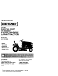
tant safety precautions.
It means
CAUTION!!I BECOMEALERTIH
YOUR
Look
for this
symbol to point out imporSAFETY
IS INVOLVED.
CAUTION:
Always disconnect spark
plug wire and place wire where it cannot
contact spark plug in order to prevent
accidental starting when setting up,
transporting,
adjusting
or making
repairs.
I
CONGRATULATIONS
on your purchase of a Sears
Tractor. It has been designed, engineered and manufactured to give you the best possible dependability and
_ performance. _
.
" . .
Should you expedence any problem you cannot easily
remedy, please contact your nearest Sears Authorized
Service CentedDepartment.
We have competent, welltrained technicians and the proper tools to service or repair
this tractor.
Please read and retain this manual. The instructions will
enable you to assemble and maintain your tractor properly.
Always observe the "SAFETY RULES".
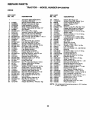
MODEL
NUMBER
SERIAL
NUMBER
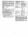
PRODUCT SPECIFICATIONS
HORSEPOWER:
944.609760
GASOLINECAPACITY
AND TYPE:
1.25 GALLONS
UNLEADED REGULAR
OIL TYPE (API-SF/SG/SH):
SAE 10W30 (above 32°F)
SAE 5W-30 (below 32°F)
OIL CAPACITY:
W/FILTER:
4.0 PINTS
W/O FILTER:3.5 PINTS
SPARK PLUG:
GAP: .040")
CHAMPION RC12YC
GROUND SPEED (MPH):
FORWARD:
1st
2rid
3rd
4th
5th
6th
REVERSE:
DATEOF PURCHASE
THE MODEL AND SERIAL NUMBERS WILL BE FOUND
ON A PLATE UNDER THE SEAT.
YOU _OULD RECORD BOTH SERIAL NUMBER AND
DATE OF PURCHASE AND KEEP IN A SAFE PLACE
FOR FUTURE REFERENCE.
MAINTENANCE
AGREEMENT
A Sears Maintenance Agreement is available on this product. Contact your nearest Sears store for details.
CUSTOMER
•
RESPONSIBILITIES
1.2
1.5
2.3
3.5
4.8
5.4
1.5
TIRE PRESSURE:
FRONT: 14 PSI
REAR: 10PSi
CHARGING SYSTEM:
15 AMPS @ 3600 RPM
BATTERY:
AMPiHR:
30
MIN. CCA:
240
CASE _SIZE: U1R
BLADE BOLT TORQUE:
27-35 FT. LBS.
i
Read and observethe safetyrules.
Fellowa regularscheduleinmaintaining,
caringforandusing
yourtractor.
FoTIowthe instructionsunder "Customer Responsibilities"
and =Storage"sectionsof thisowner'smanual.
16.0
WARNING:
This tractor Is equipped with an internal
combustion engine and should not be used on or near any
unimproved forest-covered, brush-covered or grass-covered land unlessthe engine's exhaust system is equipped
with a spark arrester meeting applicable local or state laws
(if any). Ifa spark arrester is used, it should be maintained
in effective working order by the operator.
A spark arrester for the muffler is available through your
nearest Sears AuthorizedService Centre/Department (See
REPAIR PARTS section of this manual).
3
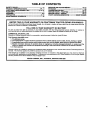
TABLE OF CONTENTS
SAFETY RULES ............................................................
2
• PRODUCT SPECIFICATIONS .......... :..._,....... ,...:...._#J_'.3
CUSTOMER RESPONSIBILITIES ..................... 3, 14-17
WARRANTY ..................................................................
4
ASSEMBLY ................................................................
6-8
OPERATION ........................................ ..................... 9-13
MAINTENANCE SCHEDULE ...................................... 14
LIMITED TWO (2) YEAR WARRANTY
SERVICE AND ADJUSTMENTS ............................ 18-23
STORAGE ...................... ............................................. 24
TROUBLESHOOTING ............................................ 25-26
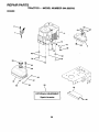
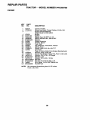
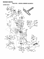
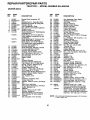
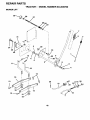
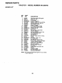
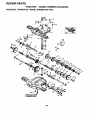
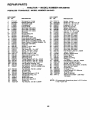
REPAIR PARTS - TRACTOR ................................. 28-43
REPAIR PARTS - ENGINE .................................... 44-53
PARTS ORDERING/SERVICE ................ BACK COVER
ON CRAFTSMAN
TRACTOR
(RIDING EQUIPMENT)
For two (2) years from date of purchase Sears Canada, Inc. will repair or replace at Sears optionfree of charge parts which are
defective as a result of material or workmanship.
FULL ONE (1) YEAR WARRANTY
GN BA'I-rERY
For one (1) year from date of purchase, if any battery included with this riding equipment proves defective in materiel or
workmanship and our testing determines the battery will not hold a charge, Sears will replac,ethe battery at no charge.
COMMERCIAL OR RENTAL USE
Warranty on Riding Equipment used for commemiel or rental purposes is limited to n!nety (90) days.
This Warranty does NOT cover:
1. Pre-dellvery set-up.
2. Tire replacement or repair caused by punctures from outside objects (such as nails, thorns, stumps, or glass).
3. Expendable items which become worn dudng normal use, such as blades, spark plug, air cleaners and belts.
4. Repairs necessary because of operator abuse or negligence, Including damaged jaoksheft or mandrel end the
failure to operate and maintain the equipment according to the Instructions contained In the Owner's Manual.
5. In Home service.
Warranty service is available by returning the Craftsman Riding Equipment to the nearest Sears Service Centre/Department in
Canada. This warranty applies only while this productis in use in Canada.
This warranty is in addition to any statutory warranty and does not exclude or limit legal rights you may have but shall run
concurrentlywith applicable provincial legislation. Furthermore, some provinces do NOT ellow limitation on how long an implied
warranty will last so the above limitationsmay not apply to you.
SEARS CANADA, INC., TORONTO, ONTARIO M5B 2B8
4
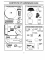
CONTENTS OF HARDWARE-. PACK
T
Parts
Bag contents
shown
full size
Parts packed separately in carton
(1) Hex Bolt
3/8-16 x 1
_Mulcher
Seat
O
Plate
;teering
Boot
Steering
Wheel
(1) Large Flat Washer
(1) Lockwasher 3/8
i
i
@
(1) Hex Bolt 5/16-18 x 1-1/4
11) Locknut 6/16-18
Pa_s Bag
Manual
(1) Shoulder Bolt
5/16-18
(1) Knob
Parts bag contents not shown full size
(2) Shoulder
Bolts
©
_2_
Gauge
(2) Washers
3/8
x 7/8 x 14 Gauge
Q(2)
R
(1) Washer 17132 x 1-3/16 x 12 Gauge
Wheel
Steering
Adapter
(2) Screws #10 x 5/8 (2) Lock Washers #101
_
°
c-31
_2_
we,d
.uts.10I--_
"_...,,J(2)
Wheels
_
(2) Keys
Steering
(2) Latch Hook
Assemblies
Washers 3/16 x 3/4 x 18 Gauge
(2) Hex Bolts
1/4-20 x 3/4
Centerlock Nuts
W.ee,
Insert
Steering
Extension
Shaft
Nuts
1/4-20
Slope Sheet
5
,
ASSEMBLY
Your new tractor has been assembled at the factory with exception of those parts left unassembled for shipping purposes.
To ensure safe and proper operation of your tractor, all parts and hardware you assemble must be tightened securely. Use
the correct tools as necessary to insure proper tightness.
TOOLS REQUIRED
FOR ASSEMBLY
INSERT
A socket wrench set will make assembly easier. Standard
• wrench sizes are listed.
(1) Phillips screwdriver Utility knife
(2) 7/16" wrenches
Tire pressure gauge
(2) 1/2" wrenches
(1) 3/4" socket with drive ratchet
(1) 9/16" wrenche
When right and left hand is mentioned in this manual, it
means when you are in the operating position (seated
behind the steering wheel).
EX BOLT
LOCK WASHER
LARGE FLAT
_
STEERINQ.--------_-_
WHEEL
\_
WASHER
_-
,j
•
_JJ
TO REMOVE TRACTOR FROM CARTON
UNPACK
•
CARTON
BOOT
Remove all accessible loose parts and parts cartons
from carton (See page 6).
Cut, from top to bottom, along lines on all four comers
of carton, and lay panels flat.
Check for any additional loose parts or cartons and
remove.
•
•
__
ADAPTER
STEERING
TASS
_
EXTENSION SHAFT
5/16 HEX BOLT
BEFORE ROLLING TRACTOR OFF SKID
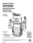
ATTACH
STEERING
WHEEL (See Fig. 1)
ASSEMBLE EXTENSION SHAFT AND BOOT
•
Slide extension shaft onto lower steedng shaft. Align
mounting holes in extension and lower shafts and
install 5116 hex bolt and Iocknut. Tighten securely.
IMPORTANT: TIGHTEN BOLT AND NUT SECURELY TO
18-22 FT. LBS TORQUE.
•
Place tabs of steering boot over tab slots in dash and
push down to secure.
INSTALL STEERING WHEEL
FIG. 1
•
Positionfront wheels ofthe tractor so they are pointing
straight forward.
•
Slide steering wheel adapter onto steering shaftextension.
•
Position steedng wheel so cross bars are horizontal
(left to right) and slide inside boot and onto adapter.
•
Assemble large flat washer, 3/8 lock washer, 3/8 hex
bolt and tighten securely.
•
Snap steering wheel insert into center of steering
wheel.
•
Remove protective materials from tractor hood and
grill.
IMPORTANT: CHECK FOR AND REMOVE ANY STAPLES
IN SKID THAT MAY PUNCTURE TIRES WHERE TRACTOR
IS TO ROLL OFF SKID.
HOW TO SET UP YOUR TRACTOR
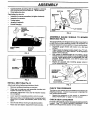
CONNECT BA'FrERY (See Rgs. 2 and 3)
CAUTION: Do not short battery terminals
contact both terminals at the same time.
by
Before
allowing
connecting
a wrench
battery,
or any otherobjectto
remove metal
bracelets, wristwatch bends, rings, etc.
Positive terminal must be connected first
to prevent sparking from accidental
grounding.
TO ROLLTRACTOR OFFSKID (SeeOperation
-section, page 10, for location and function
controls)
•
•
•
•
•
of
•
Removecardboard packingfrom seat pan andlift seat pan
toraised
position.
Press liftlever plunger and raise attachment liftlever to
its highest position.
Release parking brake by depressing clutch/brake
pedal.
Place gearshift lever in neutral (N) position.
Roll tractor forward off skid.
Remove banding holding discharge guard up against
tractor.
•
Open bettery box door and removeprotective plastic.
•
Removeterminalprotectivecapsand discard.
•
Ifthisbetteryis putintoserviceaftermonthandyearindicated
onlabel(labellocatedbetweenterminals)chargebatteryfor
minimumof one hourat 6-10 arnps.
•
FirstconnectRED betterycableto posiUve(+)terminal with
hex bolt and keps nut as shown. Tightensecurely.
6
i
ASSEMBLY
•
connect BLACK groundingcable to negative(-) terminal
with remaininghex boltandkeps nut. _ghten securely.
•
Closebatterybox door.
SEAT PAN
Open battery box doorfor:
•
Inspection for secureconnections(totightenhardware).
•
Inspection forcorrosion.
•
TesUngbattery.
•
Jumping (if required).
•
Periodiccharging.
_
SHOULDER
BOLT
ISCARD
TERMINAL
PROTECTIVE
• FLAT WASHER
ADJUSTMENT
KNOB
CAPS
KEPS
FIG. 4
i
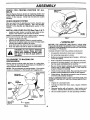
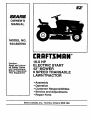
ASSEMBLE
GAUGE
DECK (See Fig. 5)
HEX BOLT
POSITIVE (RED)
CABLE
SEAT
WHEELS
TO
MOWER
The gauge wheels are designed to keep the mower deck in
proper position when operating mower. Be sure they are
properly adjusted to ensure optimum mower performance.
•
Assemble gauge wheels with tractor on a flat level
surface.
NEGATIVE
(BLACK)
CABLE
•
Adjust mower to desired cutting hei,,ght(See %0 ADJUST MOWER CU]-FING HEIGHT' in the Operation
section of this manual).
With mower in desired height of cut position, gauge
wheels shouldbe assembled sothey are slightlyoffthe
ground. Install gauge wheel in appropriate hole with
shoulder bolt, 3/8 washer, and 3/8-16 Iocknut and
tighten securely.
Repeat for opposite side installing gauge wheel in
same adjustment hole.
FIG, 2
•
SEAT
PAN
•
BOX DOOR
GAUGE WHEEL
MOUNTING
BRACKET
3/8-16
LOCKNUT
I
FIG. 3
3/S WASHER
ISHOULDER
BOLT
GAU WNEEL
E
:
iNSTALL
SEAT (See Fig. 4)
FIG. 5
Adjust seat before tightening adjustment knob.
•
Remove cardboard packing on seat pan.
CHECK TIRE PRESSURE
Place seat on seat pan and assemble shoulder bo_t,
Tighten shoulder bolt securely.
Assemble adjustment knob and flat washer loosely.
Do not tighten.
Lower seat into operating position and sit on seat,
•
The tires on your tractorwere overinflated at the factory for
shipping purposes. Correct tire pressure is important for
best cutting performance,
•
Slide seat untila comfortable position is reached which
allows you to press clutch/brake pedal all the way
down.
CHECK DECK LEVELNESS
Get off seat without moving its adjusted position.
•
Raise seat and tighten adjustment knob securely.
Reduce tire pressure to PSi shown in "PRODUCT
SPECIFICATIONS on page 3 of this manual.
7
For best cutting results, mower housing should be properly
leveled. See "TO LEVEL MOWER HOUSING" in the
Service and Adjustments section of this manual.
ASSEMBLY
CHECK
BELTS
FOR
PROPER
POSITION
OF ALL
DEFLECTOR
SHIELD
See the figures that are shown for rep!acing motion and
mower blade drive belts in the Service and Adjustments
section of this manual. Verify that the belts are routed
correctly.
CHECK
BRAKE
SYSTEM
After you learn how to Operate your tractor, check to see
that the brake is propedy adjusted. See "TO ADJUST
BRAKE" in the Service and Adjustments section of this
manual.
INSTALL
MULCHER
PLATE (See Figs. 6 & 7)
Install two latch hooks to mulcher plate using screw,
washer, lock washer, and weld nut as shown.
NOTE: Pre-assemble weld nut to latch hook by inserting
weld nut from the top with hook pointingdown.
•
•
•
•
•
LATCH
HOOKS
FIG. 7
Tighten hardware securely.
Raise and hold deflector shield in upright position.
Place front of mulcher plate over front of mower deck
opening and slide into place, as shown.
Hook front latch into hole on front of mower deck.
Hook rear latch into hole on back of mower deck.
A
,/CHECKLIST
BEFORE YOU OPERATE AND ENJOY YOUR NEW
TRACTOR, WE WISH TO ASSURE THAT YOU RECEIVE
THE BEST PERFORMANCE AN D SATISFACTION FROM
THIS QUALITY PRODUCT.
CAUTION: Do not remove discharge
guard from mower. Raise and hold
guard when attaching mulcher plate
and allow it to rest on plate while in
operation.
TO CONVERT TO BAGGING
DISCHARGING
PLEASE REVIEW THE FOLLOWING CHECKLIST:
NOTE: It is not necessaryto change blades. The mulcher
blades are designed for discharging and bagging also.
NUT
No remaining loose parts in carton.
,/
Batteryis propedy prepared and charged. (Minimum
1 hour at 6 amps).
,/
Seat is adjusted comfortably and tightened securely.
,/
All tires are propedy inflated. (For shipping purposes,
the tires were overinflated at the factory).
•/
Be sure mower deck is properly leveled side-to-side/
front-to-rear for best cutting results. (Tires must be
properly inflated for leveling).
Check mower and drive belts. Be sure they are routed
properly around pulleys and inside all belt keepers.
/
Check wiring. See that all connections are stillsecure
and wires are properly clamped.
WI-tlt,ELEARNING HOW TO USE YOUR TRACTOR, PAY
EXTRA ATTENTION TO THE FOLLOWING IMPORTANT
ITEMS:
_
'.23'
,/
/
HOOK POINTS
DOWN
LOCK
WASHER
WELD.
All assembly instructionshave been completed.
OR
Simply remove mulcher plate and store in a safe place.
Your mower is now ready for discharging or installationof
optional grass catcher accessory.
WELD NUT
,/
SCREW
,/
Engine oil is at proper level.
,/
Fuel tank is filled with fresh, clean, regular unleaded
gasoline.
Become familiar with all controls - their location and
function. Operate them before you start the engine.
\
,,/
LATCH
HOOK
HOOK
,/
LOCK
WASHER
WASHER
WELD
NUT
MULCHER
PLATE
FIG. 6
8
Be sure brake system is in safe operating condition.
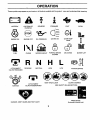
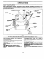
OPERATION
These symbols may appear on your tractor or in literature supplied with the product. Learn and understand their meaning.
BATTERY
CAUTION OR
WARNING
REVERSE
FORWARD
FAST
SLOW
ENG,NEON
ENG,NEOFF
O,LPRESSURE
L.G._SON
OV_,_E#PI
FUEL
CHOKE
MOWER HEIGHT
PARKING BRAKE
LOCKED
UNLOCKED
MOWER LIFT
H L
ATTACHMENT
CLUTCH ENGAGED
IGNITION
REVERSE
NEUTRAL
AI-I'ACHMENT
CLUTCH DISENGAGED
HIGH
LOW
KEEP AREA CLEAR
PARKING BRAKE
SLOPE HAZARDS
(SEE SAFETY RULES SECTION)
FREE WHEEL
(Automatic Models only)
DANGER, KEEP HANDS AND FEET AWAY
9
OPERATION
KNOW YOUR TRACTOR
READ THIS OWNER'S
MANUAL AND SAFETY RULES BEFORE OPERATING
YOUR TRACTOR
Compare the illustrationswith yourtractorto familiarize yourself with the locationsof variouscontrols and adjustments, Save
this manual for future reference.
ATTACHMENT
IGNmON
SWITCH
CLUTCH LEVER
LIGHT SWITCH
PosmoN
ATTACHMENT
LIFT LEVER
©
CLUTCH/BRAKE
PEDAL
PARffiNG
BRAKELEVER
THROTTL_CHOKE
CONTROL
GEARSHIFT
HEIGHT
ADJUSTMENT
KNOB
FIG. 8
Our tractors conform to the safety standards of the American National Standards Institute.
ATTACHMENT CLUTCH LEVER: Used to engage the
mower blades, or other attachments mounted to your
tractor.
LIFT LEVER PLUNGER: Used to release attachment lift
lever when changing its position.
AI-I'ACHMENT LIFT LEVER: Used to raise and lowerthe
mower deck or other attachments mounted to your tractor.
PARKING BRAKE LEVER: Locks Clutch/Brake Pedal into
the brake position.
GEARSHIFT LEVER: Selects the speed and direction of
tractor.
THROI-rLFJCHOKE CONTROL: Used for starting and
controlling engine speed.
CLUTCWBRAKE PEDAL: Used for clutchingand braking
the tractor and starting the engine.
HEIGHT ADJUSTMENT KNOB: Used to adjustthe mower
cutting height.
IGNITION SWITCH: Used for starting and stopping the
_engine._
LIGHT SWITCH: Turns the headlights on and off.
AMMETER: Indicates charging (+) or discharging (-) of
battery.
10
OPERATION
The operation of any tractor can result in foreign objects thrown into the eyes, which can
result in severe eye damage. Always wear safety glasses or eye shields while operating
your tractor or performing any adjustments or repairs. We recommend a wide vision
safety mask over spectacles or standard safety glasses.
IMPORTANT:LEAVINGTHE IGNmON SWITCHIN ANY
PosmoN OTHERTHAN"OFF"WILLCAUSETHE BA'I-rERYTO
BE DISCHARGED,(DEAD).
HOW TO USE YOUR TRACTOR
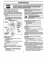
TO SET PARKING BRAKE (See Rg.9)
NOTE: Under certain conditionswhen tractor is standing idle
with the engine running, hot engine exhaust gases may cause
"browning" of grass. To eliminate this possibility,always stop
engine when stopping tractor on grass areas.
Yourtractorisequippedwithan operatorpresence sensing
switch.When engine is running,any attemptby the operator
to leavethe seat withoutfirstsettingthe parkingbrakewillshut
offthe engine.
•
Depressclutch/brakepedal intofull"BRAKE" positionand
hold.
•
PI_. oarkingbrake lever in "ENGAGED" positionand
releasepressurefrom clutch/brekepedal. Pedal should
remainin "BRAKE" position. Make sure parldngbrake
willholdtractorsecure.
J_
ATTACHMENT CLUTCH LEVER
"ENGAGED" POSITION
THROTTLE
CONTROL
pletely, as described above, before
leaving the operator's position; to empty
CAUTION:
Always
grass catcher,
etc. stop tractor com-
I
TO USE THROI'TLE CONTROL (See Rg. 9)
Alwaysoperateengineat full throttle.
•
Operating engineat lessthan full throttlereducesthe
batterychargingrate.
•
Fullthrottle offersthe bestbaggihg and mower perfor-
IGNITION KEY
POSITION
mar'Ice.
"ENGAGED"
TO MOVE FORWARD
(See Fig. 9)
"DISENGAGED"
POSITION
POSITION
The direction and speed of movement is controlled bythe
gearshift lever.
•
Start tractor with clutch/brake pedal depressed and
gearshift lever in neutral (N) position,
•
Move gearshift lever to desired position.
•
Slowly release clutch/brake pedal to start movement.
IMPORTANT: BRING TRACTOR TO A COMPLETE STOP
BEFORE SHIFTING OR CHANGING GEARS, FAILURE
TO DO SO WILL SHORTEN THE USEFUL LIFE OF YOUR
TRANSAXLE.
GEARSHIFT
LEVER
CLUTCH/BRAKE
PEDAL'DRIVE"
POSITION
HEIGHT
ADJUSTMENT
KNOB
FIG. 9
TO ADJUST MOWER CUTTING
(See Fig. 9)
STOPPING (See Fig, 9)
MOWER BLADES -
Turn knob clockwise (('_) to raise cutting height.
•
To stepgrounddrive,depressdutch/brakepedalintofull
"BRAKE" position.
Turn knob counterclockwise (1,-_) to lower cutting
height.
The cutting height range isapproximately 1-1/2" to 4". The
heights are measured from the ground to the blade tip with
the engine not running. These heights are approximate
and may vary depending upon soil conditions, height of
grass and types of grass being mowed.
Move gearshift lever to neutral (N) position.
ENGINE .... •
HEIGHT
Th_ cuttingheight iscontrolledby turningthe heightadjustment knob in desired direction.
To stop mower blades,moveattachmentdutch leverto
"DISENGAGED" position.
GROUND DRIVE •
AND BACKWARD
Move throttle controlto slowposition.
NOTE: Failureto move throttlecontrolto slowposition and
allowingengineto idlebeforestoppingmay causeengineto
"backfire".
The average lawn shouldbe cutto approximately 2-1/2
inches during the cool season and to over 3 inches
during hot months. For healthier and better looking
lawns, mow often and after moderate growth.
For best cutting performance, grass over 6 inches in
height should be mowed twice. Make the first cut
relatively high; the second to desired height.
Turn ignitionkey to"OFF position and removekey.
Always removekey when leavingtractorto prevent
unauthorizeduse.
Never use choke to stepengine.
11
OPERATION
TO OPERATE
MOWER
(See Fig. 10)
•
Yourtractor is equipped with an operator presence sensing
switch. Any attempt by the operator to leave the seat with
the engine runningand the attachment clutchengaged will
shut off the engine.
To restartmovement, slowlyrelease parkingbrake and
clutch/brake pedal.
Make all turns slowly.
•
TO TRANSPORT
•
•
Select desired height of cut.
Lower mower with attachment lift control.
•
Raise attachment lift to highest position with attachment lift control.
•
Start mower blades by engaging attachment Clutch
control.
•
When pushing or towing your tractor, be sure gearshift
lever is in neutral (N) position.
•
TO STOP MOWER BLADES - disengage attachment
clutch control.
•
Do not push or tow tractor at more than five (5) MPH.
&
NOTE: To'protect hood from damage when transporting
your tractoron a truckor a t railer,be sure hood isclosed and
secured to tractor. Use an appropriate means oftying hood
to tractor (rope, cord, etc.).
CAUTION: Do not operate the mower
without either the entire grass catcher,
on mowers so equipped, or the discharge guard in place.
ATTACHMENT
CLUTCH LEVER
"DISENGAGED"
POSITION
BEFORE STARTING THE ENGINE
CHECK ENGINE OIL LEVEL (See Fig. 16)
ATTACHMENT CLUTCH LEVER
"ENGAGED" POSITION
The engine in yourtractor has been shipped, from the
factory, already filled with summer weight oil.
LIFT LEVER
"HIGHEST"
POSITION
Check engine oil with tractor on level ground.
Unthread and remove oil fill cap/dipstick; wipe oil off.
Reinsert the dipstickintothe tube and rest oilfill cap on
the tube. Do not thread the cap onto the tube. Remove
and read oil level. If necessary, add oil until "FULL"
mark on dipstick is reached. Do not overfill.
LOWEST
POSITION
/,'
,J
For cold weather operation you should change oil for
easier starting (See "OIL VISCOSITY CHART" in the
Customer Responsibilities section of this manual).
To change engine oil, see the Customer Responsibilities section in this manual.
ADD GASOLINE
•
Fill fuel tank. Use fresh, clean, regular unleaded
gasoline with a minimum of 87 octane. (Use of leaded
gasoline will increase carbon and lead oxide deposits
and reduce valve life). Do not mix oil with gasoline.
Purchase fuel in quantities that can be used within 30
days to assure fuel freshness.
IMPORTANT: WHEN OPERATING IN TEMPERATURES
BELOW32°F(0°C), USE FRESH, CLEAN WINTER GRADE
GASOLINE TO HELP INSURE GOOD COLD WEATHER
STAFJTING.
GUARD
FIG. 10
TO OPERATE
I
&
ON HILLS
hills with slopes greater than 15° and
CAUTION:
not drive
up or down
do not drive Do
across
any slops.
WARNING: Experience indicates that alcohol blended
fuels (called gasohol or using ethanol or methanol) can
attract moisturewhich leads to separation and formation of
acids during storage. Acidic gas can damage the fuel
system of an engine while in storage. To avoid engine
problems, the fuel system should be emptied before storage of 30 days or longer. Drain the gas tank, start the
engine and let it run until the fuel lines and carburetor are
empty. Use fresh fuel next season. See Storage Instructions for additional information. Never use engine or
carburetor cleaner products in the fuel tank or permanent
damage may occur.
I
Choose the slowest speed before starting up or down
hills.
Avoid stopping or changing speed on hills.
If slowing is necessary, move throttle control lever to
slower position.
I
If stopping is absolutely necessary, pushclutch/brake
pedal quickly to brake position and engage parking
brake.
Move gearshift lever to 1st gear. Be sure you have
allowed room for tractor to roll slightly as you restart
movement.
12
CAUTION: Fill to bottom of gas tank
filler neck. Do not overfill. Wipe off any
spilled oil or fuel. Do not store, spill or
use gasoline near an open flame.
OPERATION
TO START ENGINE
(See Fig. 9)
•
When starting the engine for the first time or if the engine
has run out of fuel, it will take extra cranking time to move
fuel from the tank to the engine.
•
Sit on seat in operating position,depress clutch/brake
pedal and set parking brake.
•
Place gear shift lever in neutral (N) position.
•
Move attachment clutch to =DISENGAGED" position.
•
Move throttle control to choke position.
•
•
NOTE: Before starting, read the warm and cold starting
procedures below.
•
•
Insert keyinto ignition and turn keyclockwiseto "START"
position and release key as soon as engine starts. Do
not run starter continuously for more than fifteen seconds per minute, if the engine does "lot start after
several attempts, move throttle control to fast position,
wait a few minutes and try again. If engine stilldoes not
start, move the throttle control back to the choke
position and retry.
If grass is extremely tall, it should be mowed twice to
reduce Ipad and possible fire hazard from dried clippings. Make first cut relatively high the second to the
des red he ght.
Do not mow grass when it is wet. Wet grass will plug
mower and leave undesirable clumps. Allow grass to
dry before mowing.
Always operate engine at full throttle when mowing to
assure better mowing performance and proper discharge of material. Regulate ground speed by selecting a low enough gear to give the mower cutting
performance as well as the quality of cut desired.
Wheh operating attachments, select a ground speed
that will suit the terrain and give best performance of the
attachment bei0g used.
WARM WEATHER STARTING (50 ° F and above)
•
When engine starts, move the throttle controltothe fast
position.
•
FIG. 11 "
The attachments and ground drive can nowbe used. If
the engine does not accept the load, restart the engine
and allow it to warm up for one minute using the choke
as described above.
MULCHING
IMPORTANT:
FOR BEST PERFORMANCE, KEEP
MOWER HOUSING FREE OF BUILT-UP GRASS AND
TRASH. CLEAN AFTER EACH USE.
• The special mulching blade will recut the grass clippings many times and reduce them in size so that as
they fall onto the lawn they will disperse into the grass
and not be noticed. Also, the mulched grass will
biodegrade quickly to provide nutrients for the lawn.
Always mulch with your highest engine (blade) speed
as this will provide the best recutting action of the
blades.
COLD WEATHER STARTING ( 50 ° F and below)
•
When engine starts, allowengine to runwith thethrottle
control in the choke position until the engine runs
roughly, then move throttle control to fast position. This
may require an engine warm-up period from several
seconds to several minutes, depending on the temperature.
•
The attachments can also be used during the engine
warm-up period.
•
NOTE: If at a high altitude (above 3000 feet) or in cold
temperatures (below 32 F) the carburetor fuel mixture may
need to be adjusted for best engine performance. See "TO
ADJUST CARBURETOR" in the Service and Adjustments
section of this manual.
•
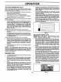
MOWINGTIPS
Tire chains cannot be used when the mower housing
is attached to tractor.
•
•
MOWING TIPS
•
Mower should be properly leveled for best mowing
performance. See "TO LEVEL MOWER HOUSING" in
the Service and Adjustments section of this manual.
The left hand side of mower should be used for trimming.
Drive so that clipPings are discharged onto the area
that has been cut. Have the cut area to the right of the
machine. This will result in a more even distnbution of
clippings and more uniform cutting.
When mowing large areas, start by turning to the right
so that clippings will discharge away from shrubs,
fences, driveways, etc. After one or two rounds, mow
in the opposite direction making left hand turns until
finished (See Fig. 11 ).
•
13
Avoidcutting your lawn when itiswet. Wet grass tends
to form clumps and interferes with the mulchingaction.
The best time to mow your lawn is the early afternoon.
At this time the grass has dried and the newly cut area
will not be exposed to the direct sun.
For best results,adjustthe mower cuttingheight sothat
the mower cuts offonly the top one-third of the grass
_lades (See Fig. 12). For extremely heavy mulching
reduce your width of cut on each pass and mow slowly.
Certain types of grass and grass conditions may require that an area be mulched a second time to completely hide the clippings. When doing a second cut,
mow across or perpendicular to the first cut path.
Change your cutting pattern from weekto week. Mow
north to south one week then change to east to west the
next week. This will help prevent matting and graining
of the lawn.
FIG. 12
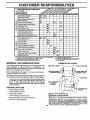
CUSTOMER RESPONSIBILITIES
MAINTENANCE
SCHEDULE
REGU
SERV,CE
'R
AS YOU COMPLETE
_ " '_,_
",/_,_s/_ _/_,_/_
_v
_
_,_
_//_"_
_'/_'_'_q'_'_'_'_'_'_,_
""
:::c:
Bg:;o::::,on
T
Check Operator Presence and
Interlock Systems
R
Check for Loose Fasteners
t
Lubrication Chart
0
A
Check
Battery Level
Sharpen/Replace
Mower Blades
Clean Battery and Terminals
i4
Check Transaxle Cooling
I_
R
l_
V/7
V'
!_
Adjust Blade Belt(s) Tension
I_s
Adjust Motion Drive Belt(s) Tension
V's
Check Engine Oil Level
V _
V'
If
Change Engine Oil
_2.3
V P
E
N
Clean
Clean Air
Air Filter
Screen
_:
G
Inspect Muffler/Spark Arraster
N
Replace
Oil Filter
(If equipped)
Clean Engine
Cooling
Fins
11_1.2
V'2
Replace Spark Plug
Replace Air Filter Paper Cartddge
_V'2
i/
V_
Replace Fuel Filter
ll_
1 * Change more ottetl when eperating under a heaw load or _ hi_n P,mbienttemperatures. 5 - If equipped v/_thedjustable syslam.
2 - Se_ce more otlan when operating In dirtyor dusty cond_ons.
6 - Not requiredifequippedwith maintenance-freebattery,
S - If eputpped w#h oltfiner, ot_angedil eveP/50 hours.
7 - "l-_htenfm_t axle pivot bdit to 35 ft,-Ibs, maximum.
4 - Replace blades more o(ten when mowingin sandy soil,
Do not overUghten,
GENERAL RECOMMENDATIONS
LUBRICATION
The warranty on this tractor does not cover items that have
been subjected to operator abuse or negligence. To
receive full value from the warranty, operator mustmaintain
tractor as instructed in this manual.
CHART
@
@
@
Some adjustments will need to be made periodically to
properly maintain your tractor.
BEARING
'FRONT WHEEL@
BEARING ZERK
ZERK
All adjustments in the Service and Adjustmentssection of
this manual should be checked at least once each season.
®
Once a year you should replace the spark plug, clean
or replace air filter, and check blades and belts for
wear. A new spark plug and clean air filter assure
proper air-fuel mixture and help your engine runbetter
and last longer.
BEFORE
-;,
•
(_)
CLUTCH
PIVOT(S)
EACH USE
IEARSHIFT@
PIVOTS
Check engine oil level.
Check brake operation.
Check tire pressure.
(_)SAE
Check operator presence and
@GENERAL
interlock systems for proper operation.
Check for loose fasteners.
@REFER
30 OR lOW30 MOTOR OIL
PURPOSE GREASE
TO CUSTOMER RESPONSIBILITIES
"ENGINE"
SECTION
IMPORTANT:
DO NOT OIL OR GREASE THE PIVOT POINTS
WHICH HAVE SPECIAL NYLON BEARINGS.
VISCOUS LUBRICANTS WILL ATTRACT DUST AND DIRT THAT WILL SHORTEN
THE LIFE OF THE SELF-LUBRICATING
BEARINGS.
IF YOU
FEEL THEY MUST BE LUBRICATED,
USE ONLY A DRY, POW-
14
DERED
GRAPHITE
TYPE LUBRICANT
SPARINGLY.
CUSTOMER RESPONSIBILITIES
TRACTOR
TRAILING
EDGE UP
Always observe safety rules when performing any maintenance.
\
MANDREL
ASSEMBLY
BLADE
CENTER
HOLE
BRAKE OPERATION
If tractor requires more than six (6) feet stopping distance
at high speed in highest gear, then brake mustbe adjusted.
(See "TO ADJUST BRAKE" in the Service and Adjustments section of this manual).
FLAT WASHEF
LOCK WASHER
TIRES
•
Maintain proper air pressure in all tires (See =PRODUCT SPECIFICATIONS" section of this manual).
•
Keep tires free of gasoline, oil, or insect controlchemicals which can harm rubber.
_'.-
*A GRADE 8 HEAT TREATED BOLT CAN BE
IDENTIFIED BY SiX LINES ON THE BOLT HEAD
FIG. 13
Avoid stumps, stones, deep ruts, sharp objects and
other hazards that may cause tire damage.
TO SHARPEN
NOTE; To seal tire punctures and prevent flat tires due to
slow leaks, tire sealant may be purchased from your local
parts dealer. Tire sealant also prevents tire dry rot and
corrosion.
OPERATOR
PRESENCE
•
When the engine is running,any attempt by the operator to leave the seat without first setting the parking
brake should shut off the engine.
•
•
•
To check blade balance, you will need a 5/8" diameter
steel bolt, pin, ora cone balancer. (When using a cone
balancer, follow the instructions supplied with balancer).
Slide blade on to an unthreaded portion of the steel bolt
or pin and hold the bolt or pin parallel with the ground.
If blade is balanced, it should remain in a horizontal
position. If either end of the blade moves downward,
sharpen the heavy end until the blade is balanced.
CARE
REMOVAL
CENTER '_
(See Fig. 13)
•
Raise mower to highest position to allow access to
blades.
•
Remove hex bolt, lockwasher and flat washer secudng
blade.
•
Install new or resharpened
towards deck as shown.
OR PIN
FIG. 14
blade with trailing edge up
---IMPORTANT:
TO ENSURE
PROPER
ASSEMBLY,
CENTER HOLE IN BLADE MUST ALIGN WITH STAR ON
MANDREL ASSEMBLY.
•
The blade can be sharpened with a file or on a gdnding
wheel. Do not attempt to sharpen while on the mower.
•
For best results mower blades must be kept sharp. Replace bent or damaged blades.
BLADE
•
NOTE: Do not use a nail for balancing blade. The lobes of
the center hole may appear to be centered, but are not.
When the engine is running and the attachment clutch
is engaged, any attempt by the operator to leave the
seat should shut off the engine.
The attachment clutchshouldnever operate unlessthe
operator is in the seat.
BLADE
(See Fig. 14)
Care should be taken to keep the blade balanced. An
unbalanced blade will cause excessive vibration and eventual damage to mower and engine.
Be sure operator presence and interlock systems are
working properly. If your tractor does not function as
described, repair the problem immediately.
The engine should not start unless the clutch/brake
pedal isfully depressed and attachement clutchcontrol
is in the disengaged position.
BLADE
NOTE: We do notrecommend sharpening blade - but ifyou
do, be sure the blade is balanced.
SYSTEM
•
HEX BOLT (GRADE 8)*
Reassemble hex bolt, lock washer and flat washer in
exact order as shown.
•
Tighten bolt securely (27-35 Ft. Lbs. torque).
IMPORTANT: BLADE BOLTIS GRADE 8 HEAT TREATED.
15
CUSTOMER RESPONSIBILITIES
BATrERY
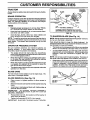
Your tractor has a battery charging system which is sufficient for normal use. However, period!c charging of the
battery with an automotive charger will extend its life.
•
Catch oil in a suitable container.
•
Remove oil fillcap/dipstick. Be careful not to allow dirt
to enter the engine when changing oil.
•
Remove drain plug.
•
•
Keep battery and terminals clean.
•
Keep battery bolts tight.
After oil has drained completely, replace oil drain plug
and tighten securely.
•
•
Keep small vent holes open.
Recharge at 6-10 amperes for 1 hour.
Refill engine with oil through oil filldipstick tube. Pour
slowly. Do not overfill For approximate capacity see
"PRODUCT SPECIFICATIONS" sectionofthis manual.
TO CLEAN BA'I-IERY AND TERMINALS
•
Corrosion and dirt on the battery and terminals can cause
the battery to "leak" power.
•
Open battery box door.
•
Disconnect BLACK battery cable first then RED battery cable and remove battery from tractor.
Rinse the battery with plain water and dry.
Use gauge on oil fill cap/dipstick for checking level.
Insertdipstickintothetube and restthe oilfillcap on the
tube. Do notthread the cap onto the tube when taking
reading. Keep oil at "FULL" line on dipstick. Tighten
cap onto the tube securely when finished.
AIR CLEANER
, WING NUT
Clean terminals and battery cable ends with wire brush
until bright.
•
Coat terminals with grease or petroleum jelly.
•
Reinstall battery (See "CONNECT BATI'ERY" in the
Assembly section of this manual).
V-BELTS
Check V-belts for deterioration and wear after 100 hours of
operation and replace if necessary. The belts are not
adjustable. Replace belts if they begin to slip from wear.
TRANSAXLE
COOLING
Keep trensaxle free from build-up of dirt and chaff which
can restrict cooling.
PAPER CARTRIDGE
ENGINE
3LEANER
BASE
CAP/DIPSTICK
LUBRICATION
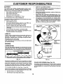
Only use high quality detergent oil rated with API service
classificationSF, SG or SH. Select the oil'sSAE viscosity
grade according to your expected operating temperature.
SAE VISCOSITY GRADES
-20*
-30"
0°
-20 °
TEMPERATURE
30*
-I0 °
32 °
40 _
O"
60"
10 °
80 °
20 °
30 °
40 °
PLUG
RANGE ANTICIPATED BEFORE NEXT OIL CHANGE
FIG° 15
FIG. 16
Change the oil after every 50 hours of operation or at least
once a year if the tractor is not used for 50 hours in one year.
CLEAN
--Check the crankcase oil level before starting the engine
and after each eight (8) hours of operation. Tighten oil fill
cap/dipstick securely each time you check the oil level.
TO CHANGE ENGINE OIL (See Figs. 15 and 16)
Determine temperature range expected before oil change.
All oil must meet API service classification SF, SG, or SH.
•
Be sure tractor is on level surface.
•
AIR SCREEN
(See Fig. 16)
Air screen must be kept free of dirt and chaff to prevent
engine damage from overheating. Clean with a wire brush
or compressed air to remove dirt and stubborn dried gum
fibers.
Oil will drain more freely when warm.
16
CUSTOMER RESPONSIBILITIES
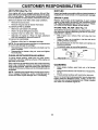
AIR FILTER (See Fig. 16)
MUFFLER
Your engine will not run properly using a dirty air filter.
Clean the foam pre-cleaner after every 25 hours of operation or every season. Service paper cartridge every 100
hours of operation or every season, whichever occursfirst.
Inspect and replace corroded muffler and spark arrester (if
equipped) as it could create a fire hazard and/or damage.
Service air cleaner more often under dusty conditions.
Remove knob and cover.
Replace spark plugs at the beginning of each mowing
season or after every 100 hours of use, whichever comes
first. Spark plug type and gap setting is shown in "PRODUCT SPECIFICATIONS" section of this manual.
SPARKPLUGS
•
Remove wing nut and air cleaner from base.
TO SERVICE PRE-CLEANER
IN-LINE
Slide foam pre-cleaner off cartridge.
FILTER
(See Fig, 17)
The fuel filtershould be replaced once each season. If fuel
filter becomes clogged, obstructingfuel flow to carburetor,
replacement is required.
Wash it in liquid detergent and water.
Squeeze it dry in a clean cloth. Allow it to dry.
•
Saturate it in engine oil. Wrap it in clean, absorbent
cloth and squeeze to remove excess oil.
TO SERVICE CARTRIDGE
•
FUEL
With engine cool, remove filter and plug fuel line
sections.
Place new fuel ,,,{er in position in fuel line with arrow
pointing towards carburetor.
Replace a dirty, bent, or damaged cartridge.
NOTE: Do not wash the paper cartridge or use pressurized
air, as this will damage the cartridge.
Be sure there are no fuel line leaks and clamps are
properly positioned.
•
Immediately wipe up any spilled gasoline.
Reinstall the pre-cleaner (cleaned and oiled) over the
paper cartridge.
CLAMP
Reassemble air cleaner, wing nut, cover and tighten
knob securely.
CLEAN AIR INTAKE/COOLING
AREAS
FUEL RLTER _AMP
To insure proper cooling, make sure the grass screen,
cooling fins, and other external surfaces of the engine are
kept clean at all times.
FIG. 17
Every 100 hours of operation (more often under extremely
dusty, dirty conditions), remove the blower housing and
other cooling shrouds. Clean the cooling fins and external
surfaces as necessary. Make sure the coolingshroudsare
reinstalled.
CLEANING
NOTE: Opereting the engine with a blocked grass screen,
dirty or plugged cooling fins, and/or cooling shrouds removed will cause engine damage due to overheating.
•
Clean engine, battery, seat, finish, etc. of all foreign
matter.
•
Keep finished surfaces and wheels free of all gasoline,
oil, etc.
•
Protect painted surfaces with automotive type wax.
We do not recommend using a garden hose to clean your
tractor unless the electrical system, muffler, air filter and
carburetor are covered to keep water out. Water in engine
can result in a shortened engine life.
17
SERVICE AND ADJUSTMENTS
&
CAUTION:
•
•
•
•
•
•
BEFORE PERFORMING ANY SERVICE OR ADJUSTMENTS:
Depress clutchrorake pedal fully and set parking brake. Place gearshift lever in neutral (N) position.
Place attachment clutch in "DISENGAGED" position.
Turn Ignition key "OFF" and remove key.
Make sure the blades and all moving parts have completely stopped.
Disconnect spark plug wire from spark plug and place wire where it cannot come in contact with
plug,
TRACTOR
CLUTCH LEVER
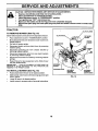
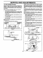
TO REMOVE
MOWER
(See Fig. 18)
CLUTCH ROD
Mower willbe easier to remove from the rightside of tractor.
•
•
•
RETAINER
SPRING
Place attachment clutch in "DISENGAGED" position.
Move attachment littlever forward to lower mower to its
lowest position.
ENGINE
PULLEY
SUSPENSION
Roll belt off engine pulley.
Disconnect clutch rod from clutch lever by removing
retainer spring.
•
Disconnect anti-sway bar from chassis bracket by
removing retainer spring.
•
Disconnect suspension arms from rear deck brackets
by removing retainer springs.
FRONT
UNK
•
Disconnect front links from deck by removing retainer
springs.
•
Raise lift lever to raise suspension arms. Slide mower
out from under tractor.
IMPORTANT:
IF AN ATTACHMENT OTHER THAN THE
MOWER IS TO BE MOUNTED TO THE TRACTOR, BE
REMOVE THE FRONT LINKS.
RETAINER
SPRING
AN_-SWAYBAR
TO INSTALL
•
MOWER
(See Fig. 18)
Raise attachment lift lever to its highest position.
Slide mower under tractor with dischargeguard to right
side of tractor.
•
•
RETAINER
SPRINGS
(BOTH SIDES)
FIG. 18
Lower lift lever to its lowest position.
Install mower in reverse order of removal instructions.
18
RETAINER
SPRINGS
(BOTH SIDES)
SERVICE AND ADJUSTMENTS
TO LEVEL MOWER HOUSING
FRONT-TO-BAcK
Adjustthe mower while tractor is parked on level ground or
driveway. Make sure tires are properly inflated (See
=PRODUCT SPECIFICATIONS" section ofthis manual). If
tires are over or undednflated, you will not preperly adjust
your mower.
IMPORTANT:
DECK MUST BE LEVEL SIDE-TO-SIDE.
IF
THE FOLLQWING
FRONT-TO-BACK
ADJUSTMENT
IS
NECESSARY, BE SURE TO ADJUST BOTH FRONT LINKS
EQUALLY
SO MOWER
WILL STAY LEVEL SIDE-TOSIDE.
(See Figs. 21 and 22)
To obtain the best cutting results, the mower housing
shouldbe adjusted so that the front isapproximately 118"to
1/2" lower than the rear when the mower is in its highest
position.
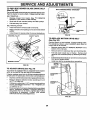
SIDE-TO-SIDE ADJUSTMENT (See Figs. 19 and 20)
Raise mower to its highest position•
•
ADJUSTMENT
At the midpoint of bothsides of mower, measure height
from bottom edge of mower to ground. Distance =A"on
both sides of mower should be the same or within 114"
of each other.
Check adjustment on right side of tractor. Measure distance =D"directly in front and behind the mandrel at bottom
edge of r_ower housing as shown.
•
To raise one side of mower, tighten lift link adjustment
nut on that side.
Before makingany necessary adjustments, check that
bothfront links are equal in length. Bothlinks shouldbe
approximately t 0-3/8".
•
To lower one side of mower, loosen lift link adjustment
nut on that side.
If linksare not equal in length, adjust one linkto same
length asother link.
•
NOTE: Each full turn of adjustment nut wUlchange mower
height about 1/8".
To lower front of mower loosen nut "E" on both front
links an equal number of turns.
•
When distance "D" is 1/8" to 1/2" lower at front than
rear, tighten nuts "F" against trunnion on both front
links.
•
To raise front of mower, loosen nut"F" from trunnionon
both front links. Tighten nut "1_"on both front links an
equal number of turns.
•
When distance "D" is 1/8" to 1/2" lower at front than
rear, tighten nut "F" against trunnionon both front links•
•
Recheck side-to-side adjustment.
If adjustment is necessary, make adjustment on one
side of mower only.
•
Recheck measurements after adjusting.
BOTTOM EDGE
OF MOWER TO
GROUND
BOTTOM EDGE
OF MOWER TO
GROUND
V OROUNDL,.E
7--JT "
\
I
.... !
MANDREL
FIG. 19
SUSPENSION
ARM
FIG. 21
BOTH FRONT LINKS MUST BE EQUAL IN LENGTH
LIFT LINK
ADJUSTMENTNUT
FIG. 20
LINKS
19
TRUNNION
FIG. 22
SERVICE AND ADJUSTMENTS
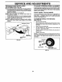
TO REPlaCE
(See Fig. 23)
MOWER
BLADE
DRIVE
BELT
WITH PARKING BRAKE "ENGAGED"
The mower blade drive belt may be replaced without tools.
Park the tractor on level surface. Engage parking brake.
BELT REMOVAL •
NUT "A"
Remove mower from tractor (See =TO REMOVE
MOWER" in this section of this manual).
Work belt off both mandrel pulleys and idler pulleys.
/
•
Pull belt away from mower.
BELT INSTALLATION •
Install new belt in reverse order of removal.
•
Make sure belt isin all pulley grooves and inside all belt
guides.
Install mower in reverse order of removal instructions.
•
MANDRELPULLEY
_
_M
NUT
OPERATING
_
ARM
FIG. 24
IDLER PttLLEYS
TO REPLACE
(See Fig. 25)
MOTION
DRIVE
BELT
Park the tractor on level surface. Engage parking brake.
For assistance, there is a belt installation guide decal on
bottom side of left footrest.
•
•
MANDRELPULLEY
BRAKE
Remove belt from stationary idler and clutching idler.
Pull belt slack toward rear of tractor. Remove belt
upwards from transaxle pulley by deflecting belt keepers.
•
Pull belt toward frontoftractor and remove downwards
from around engine pulley.
•
Install new belt by reversing above procedure.
ENGINE_
PULLEY
FIG. 23
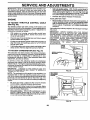
TO ADJUST
Remove mower (See =TO REMOVE MOWER" in this
section of this manual,)
CLUTCHING
IDLER
(See Fig. 24)
Your tractor is equipped with an adjustable brake system
which is mounted on the right side of the transaxle.
STATIONARY "_
IDLER
If tractor requires more than six (6) feet stopping distance
at high speed in highest gear, then brake mustbe adjusted.
•
•
Depress clutch/brake pedal and engage parkingbrake.
Measure distance between brake operating arm and
nut "A" on brake rod.
•
If distance isother than 1-1/2", loosen jam nut and turn
nut "A" until distance becomes 1-1/2". Retighten jam
nut against nut =A".
•
Road test tractorfor properstopping distance as stated
above. Read ust if necessary. If stopping distance is
st greater than six (6) feet in highest gear, further
maintenance is necessary. Contact your nearest
authorized service center/department.
....
TRANSAXLE,_
PULLEY
FIG. 25
20
SERVICE
TRANSAXLE
ADJUSTMENT
AND ADJUSTMENTS
GEAR SHIFT LEVER
TO ADJUST STEERING
(See Fig. 26)
WHEEL ALIGNMENT
If steering wheel crossbars are not horizontal (left to right)
when wheel_ are positionedstraightforward, remove steering wheel and reassemble per instructionsin the Assembly
section of this manual.
The transaxle should be in neutral when the gear shift lever
is in neutral (N) (lock gate) position. The adjustment is
preset at the factory; however, ifadjustment isneeded,
proceed as follows:
•
Make sure transaxle is in neutral (N).
NOTE: When the tractor rear wheels move freely, the
transaxle is in neutral.
•
Loosen adjustment bolt in front of the right rear wheel.
•
Positionthe gear shift lever in the neutral (N) position.
•
Tighten adjustment bolt securely.
NOTE: If additional clearance is needed to get to adjustment bolt, move mower deck height to the lowest
position.
FRONT WHEEL TOE-IN/CAMBER
The front wheel toe-in and camber are not adjustable on
your'tractor. If damage has occurred to affect the front
wheel toe-in or camber, contact your nearest authorized
service center/department.
TO REMOVE WHEEL
(See Fig. 27)
GEARSHIFT LEVER
FOR
REPAIRS
•
Block up axle .securely.
•
Remove axle cover, retaining ringand washers toallow
wheel removal (rear wheel contains a square key - Do
not lose):
•
Repair tire and reassemble.
•
On rear wheels only: align grooves in rear wheel hub
and axle. Insert square key.
•
Replace washers and snap retaining ring securely in
axle groove.
•
Replace axle cover.
NOTE: To seal tire punctures and'prevent flat tires due to
slow leaks, tire sealant may be purchased from your local
parts dealer. Tire sealant also prevents tire dry rot and
corrosion.
NEUTRAL
LOCK GATE
ADJUSTMENT
BOLT
WASHERS__
FIG. 26
L
RING '
AXLE COVER
SQUARE KEY
(REAR WHEEL ONLY)
FIG. 27
21
SERVICE
TO STARTENGINE
AND ADJUSTMENTS
WITH A WEAK BATTER:Y
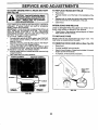
To REPLACE HEADLIGHT BULB
(See Fig. 28)
•
Raise hood.
•
Pull bulb holder out of the hole in the backside of the
grill
•
Replace bulb in holder and push bulb holder securely
back into the hole in the backside of the grill.
Close hood.
h
I&
ate explosive gases. Keep sparks, flame
and smoking materials away from batteries.
wear batteries
eye protection
CAUTION:Always
Lead-acid
generwhen around batteries.
•
If your battery is too weak to start the engine, it should be
recharged. If =jumper cables" are used for emergency
starting, follow this procedure:
IMPORTANT: YOUR TRACTOR IS EQUIPPED WITH A 12
VOLT NEGATIVE GROUNDED SYSTEM. THE OTHER
VEHICLE MUST ALSO BE A 12 VOLT NEGATIVE
GROUNDED SYSTEM. DO NOT USE YOUR TRACTOR
BATTERY TO START OTHER VEHICLES.
TO ATTACH JUMPER CABLES Connect each end of the RED cable to the POSITIVE
(+) terminal of each battery, taking care not to shc:'t
against chassis.
•
Connect one end of the BLACK cable to the NEGATIVE (-) terminal of fully charged battery.
•
Connect the other end of the BLACK cable to good
CHASSIS G ROUND, away from fuel tank and battery.
TO REMOVE CABLES, REVERSE ORDER •
BLACK cable first from chassis and then from the fully
charged battery.
•
RED cable last from both batteries.
PosmvE TERMINAL
INTERLOCKS
AND RELAYS
Loose or damaged wiring may cause your tractor to run
poorly, stop running, or prevent it from starting.
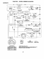
Checkwiring. See electrical wiring diagram in Repair
Parts section of this manual.
TO REPLACE
FUSE
Replace with 30 amp automotive-type plug-in fuse. The
fuse holder is located behind the dash.
TO REMOVE
HOOD AND GRILL (See Fig. 29)
•
Raise hood.
•
Unsnap headlight wire connector.
•
Stand in frontoftractor. Grasp hood at sides, tilttoward
engine and lift off of tractor.
•
To replace, reverse above procedure.
NEGATIVE TERMINAL
HOO_
WIRE
HEADLIGHT
CONNECTOR
-7
°
=
FIG. 29
FIG. 28
22
SERVICE AND ADJUSTMENTS
Maintenance, repair, or replacement of the emission control devices and systems, which are being done at the
customers expense, may be performed by any non-road
engine repair establishment or individual.Warranty repairs
must be performed byan authorized engine manufacturer's
service outlet.
•
•
Recheck idle speed. Readjust if necessary.
ACCELERATION TEST -
ENGINE
•
TO ADJUST THROTTLE
(See Fig. 30)
CONTROL
CABLE
The throttle control has been preset at the factory and
adjustment should not be necessary. Check adjustment as
described below before loosening cable. If adjustment is
necessary, proceed as follows:
•
With engine not running, move throttle control lever
from slow to choke position. Slowly move lever from
choke to fast position.
•
Check to see if hole in throttle lever and hole in speed
control bracket are aligned.
•
If holes are not aligned, loosen cable clamp screw and
align the holes by inserting a pencil or a 1/4" drill bit
through both holes.
•
Pullthrottle cable up to remove slack and tighten cable
clamp screw. Remove alignment pencil or drill bit.
TO ADJUST
CARBURETOR
Idle fuel needle setting - With throttle control lever in
slowposition,tum idlefuelad ustment need e n (c ockwise) until engine begins to die and then turn out
(counterclockwise)untilengine runsrough.Tum needle
to a point midway between those two positions.
Move throttle control lever from slow to fast position. If
engine hesitates or dies, turn idle fuel adjusting needle
out (counterclockwise) 1/8 turn. Repeat test and continue to adjust, if necessary, until engine accelerates
smoothly.
High spe§d stop isfactory adjusted. Do not adjust- damage
may result.
IMPORTANT:
NEVER TAMPER WITH THE ENGINE
GOVERNOR, WHICH IS FACTORY SET FOR PROPER
ENGINE SPEED. OVERSPEEDING THE ENGINE ABOVE
THE FACTORY HIGH SPEED SETTING CAN BE
DANGEROUS. IF YOU THINK THE ENGINE-GOVERNED
HIGH SPEED NEEDS ADJUSTING, CONTACT YOUR
NEAREST
AUTHORIZED
SERVICE
CENTER/
DEPARTMENT, WHICH HAS PROPER EQUIPMENT AND
EXPERIENCE
TO
MAKE
ANY
NECESSARY
ADJUSTMENTS.
CABLE
CLAMP
SCREW
(See Fig. 31)
SPEED(
BRACKET
The carburetor has been preset at the factory and adjustment shouldnot be necessary. However, minor adjustment
may be required to compensate for differences in fuel,
temperature, altitude or load. If the carburetor does need
adjustment, proceed as follows:
In general, turning the adjusting needles in (clockwise)
decreases the supply of fuel to the engine giving a leaner
fuel/air mixture. Turning the adjustingneedles out (counterclockwise) increases the supply offuel to the engine giving
a richer fuel/air mixture.
IMPORTANT:
DAMAGE
SEATS IN CARBURETOR
TURNED IN TOO TIGHT.
THROTTLE
LEVER
TO THE NEEDLES AND THE
MAY RESULT IF NEEDLE IS
FIG. 30
IDLE SPEED
ADJUS_NG
NOTE: The carburetor on this engine is low emission. It is
equipped with an idle fuel adjusting needle with a limiter
cap, whichallowssome adjustment withinthe limitsallowed
by the cap. Do not attempt to remove the limiter cap. The
limiter cap cannot be removedwithoutbreakingthe adjusting
needle.
Be sure you have a clean air filter and the throttle
control cable is adjusted properly (see above).
Start engine and allow to warm for five minutes. Make
adjustmentswith engine runningand shiff/motioncontrol
lever in neutral (N) position_
Idle sDeed setting - With throttle control lever in slow
position, engine should idle at 1750 RPM. If engine
idlestoo slow or fast, turn idlespeed adjustingscrew in
or out until correct idle is attained.
ADJUSTING
NEEDLE
FIG. 31
23
STORAGE
.
!
Immediately prepare your tractor for storage at the end of
the season or if the tractor will not be used for 30 days or
ENGINE
n'lore.
FUEL SYSTEM
IMPORTANT:
IT IS IMPORTANT
TO PREVENT GUM
DEPOSITS
FROM FORMING
IN ESSENTIAL
FUEL
SYSTEM PARTS SUCH AS CARBURETOR, FUEL FILTER,
FUEL HOSE, OR TANK DURING STORAGE.
ALSO,
EXPERIENCE
INDICATES THAT ALCOHOL
BLENDED
FUELS (CALLED GASOHOL OR USING ETHANOL OR
METHANOL) CAN ATTRACT MOISTURE WHICH LEADS
TO SEPARATION AND FORMATION OF ACIDS DURING
STORAGE=,
ACIDIC GAS CAN DAMAGE THE FUEL
SYSTEM O]: AN ENGINE WHILE IN STORAGE.
gasoline in the tank inside a building
where
fumes
may reach an open flame
CAUTION:
Neveratorethetractorwith
or spark. Allow the engine to cool
before storing in any enclosure.
TRACTOR
Remove mower from tractor for winter storage. When
mower is to be stored for a period of time, clean it thoroughly, remove all dirt, grease, leaves, etc. Store in a
clean, dry area.
•
Clean entire tractor (See"CLEANING" in the Customer
Responsibilities section of this manual).
•
Inspect and replace belts, if necessary (See belt replacement instructionsin the Service and Adjustments
section of this manual).
Be sure that all nuts, bolts and screws are securely
fastened. Inspect moving parts for damage, breakage
and wear. Replace if necessary.
•
Touch up all rusted or chipped paint surfaces; sand
lightly before painting.
•
•
Start the engine _lnd let it run until the fuel lines and
carburetor are empty.
•
Never useengine or carburetor cleaner products in the
fuel tank or permanent damage may occur.
ENGINE OIL
Drain oil (with engine warm) and replace with clean engine
oil. (See "ENGINE" in the Customer Responsibilities
section of this manual).
Fully charge the battery for storage.
CYLINDER(S)
After a period of time in storage, battery may require
recharging.
•
•
Use fresh fuel next season.
BA'I-rERY
•
Drain the fuel tank.
NOTE: Fuel stabilizer is an acceptable alternative in
minimizing the formation of fuel gum deposits during storage. Add stabilizer to gasoline in fuel tank or storage
container. Always follow the mix ratio found on stabilizer
container. Run engine at least 10 minutes after adding
stabilizer to allowthe stabilizer to reach the carburetor. Do
not drainthe gas tank and carburetor if usingfuel stabilizer.
Lubricate as shown in the Customer Responsibilities
section of this manual.
•
•
•
Remove spark plug(s).
To help prevent corrosion and power leakage during
long periods of storage, battery cables should be
disconnected and batterycleaned thoroughly(see"TO
CLEAN BATTERY AND TERMINALS in the Customer Responsibilities section of this manual).
•
Pour one ounce of oil through spark plug hole(s) into
cylinder(s).
•
Turn ignitionkeyto"START" positionfor afewseconds
to distribute oil.
After cleaning, leave cables disconnected and place
cables where they cannot come in contact with battery
terminals.
•
Replace with new spark plug(s).
OTHER
If battery is removed from tractor for storage, do not
store battery directly on concrete or damp surfaces.
E_onot store gasoline from one season to another.
•
Replace your gasoline can if your can starts to rust.
Rust and/or dirt in your gasoline will cause problems.
If possible, store your tractor indoors and cover it to
give protection from dust and dirt.
Cover your tractor with a suitable protective cover that
does not retain moisture. Do not use plastic. Plastic
cannot breathe which allows condensation to form and
will cause your tractor to rust.
IMPORTANT: NEVER COVER TRACTOR WHILE ENGINE
AND EXHAUST AREAS ARE STILL WARM.
24
i
TROUBLESHOOTING
POINTS
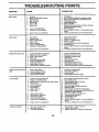
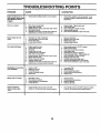
PROBLEM
CAUSE
CORRECTION
Will not start
1.
Out of fuel
1.
Fill fuel tank.
2.
3.
a.
5.
6.
7.
Engine not =CHOKED" properly.
Engine flooded.
Bad spark plug.
Dirty air tilter.
Dirty fuel tilter.
Water in fuel.
2.
3.
4.
5.
6.
7.
8.
9.
Loose or damaged wiring.
Carburetor out of adjustment.
8.
9.
See =TO START ENGINE" in Operation section.
Wait several minutes before attempting to start.
Replace spark plug.
Clean/replace air tilter.
Replace fuel tilter.
Drain fuel tank and carburetor, refill tank with fresh
gasoline and replace fuel tilter.
Check all wiring.
See =To Adjust Carburetor" in Service Adjustments
10.
Hard to start
_0.
Engine valves out of adjustment.
section.
Contact an authorized service center/department.
1.
2.
3.
4.
5.
6.
7.
Dirty air filter.
Bad spark plug.
Weak or dead battery.
Dirty fuel filter.
Stale or dirty fuel.
Loose or damaged widng.
Carburetor out of adiustmant.
t.
2.
3.
4.
5.
6.
7.
Clean/replace air filter.
Replace spark plug.
Pschar_ _ Jr replace battery.
Replace fuel tilter.
Drain fuel tank and refill wtth fresh gasoline.
Check all wiring.
See =To Adjust Carburetor" in Service Adjustments
section.
8.
Engine valves out of adjustment.
8.
Contact an authorized service centsr/department.
Engine will not turn over
1.
2.
3.
4.
5.
6.
7.
8.
9.
Clutch/brake pedal not depressed.
Attachment clutch is engaged.
Weak or dead battery.
Blown fuse.
Corroded battery terminals.
Loose or damaged widng.
Faulty ignition switch.
Faulty solenoid or starter.
Faulty operator presence switch(as).
I.
2.
3.
4.
5.
6.
7.
8.
9.
Depress clutch/brake pedal.
Disengage attachment clutch.
Recharge or replace battery.
Replace fuse.
Clean battery terminals.
Check all wiring.
Check/replace ignition switch.
Checklreplaoe solenoid or starter.
Contact an authorized sent;ce canter/department.
Engine clicks but will not
start
1,
2.
3.
4.
Weak or dead battery.
Corroded battery terminals.
Loose or damaged widng.
Faulty solenoid or starter,
1.
2.
3.
4.
Recharge or replace battery.
Clean battery terminals.
Check all wiring.
Checldreplace solenoid or starter.
Loss of power
1.
2.
Cutting too much grass/too fast.
Throttle in =CHOKE" position.
3.
4.
5.
6.
7.
8.
9.
Build-up of grass, leaves and trash under mower.
Dirty air tilter.
Low oil leval/dirty oil.
Faulty spark plug.
Dirty fuel filter.
Stale or dirty fuel.
Water in fuel.
1.
2.
3.
4.
5.
6.
7.
8.
9.
Set in =Higher Cut" position/reduce speed.
Adjust throttle control.
Clean underside of mower housing.
CIeatYreplace air filter.
Check oil level/change oil.
Clean and regal:)or change spark plug.
Replace fuel tilter.
Drain fuel tank and refill with fresh gasoline.
Drain fuel tank and carburetor, retill tank with fresh
gasoline and replace fuel tilter.
Connect and tighten spark plug wire.
Clean engine air screen/fins.
CtearVreplace muffler.
Check all widng.
See =To Adjust Carburetor" in Service Adjustments
section.
Contact an authorized sen_icecentarldepartmant`
Excessive vibration
10.
11.
12.
13.
14.
Spark plug wire loose.
Dirty engine air ssreenfiins.
Dirty/clogged muffler.
Loose or damaged wiring.
Carburetor out of adjustment,
10.
11.
12.
13.
14.
15.
Engine valves out of adjustment.
15.
1.
2.
3.
Worn, bent or loose blade.
Bent blade mandret.
Loose/damaged part(s).
1.
2.
3.
25
Replace blade. Tighten blade bolt.
Replace blade mandrel.
Tighten loose part(s). Replase damaged parts.
TROUBLESHOOTING.
PROBLEM
CAUSE
POINTS
CORRECTION
1.
Faulty operator-safety presence control system.
1.
Check wiring, switches and connections. If not
corrected, contact an authodzed service center/
department,
1.
2.
Worn, bent or loose blade.
Mower deck not level,
1.
2.
Replace blade. Tighten blade bolt.
Level mower deck.
3.
4.
Buildup of grass, leaves, and trash under mower.
Bent blade mandrel.
5.
Clogged mower deck vent holas from buildup of
grass, leaves, and trash around mandrels.
3.
4.
5_
Clean underside of mower housing.
Replace blade mandrel,
Clean around mandrels to open vent holes.
Mower blades will not
rotate
1,
Obstruction in clutch mechanism.
2.
3,
4.
Worn/damaged mower dnve belt.
Frozen idler pulley.
Frozen blade mandrel.
1,
2.
3.
4.
Remove
Replace
R_place
Replace
Poor grass discharge
1,
2.
3,
4.
5.
6.
7.
8,
Engine speed too slow.
Travel speed too fast.
Wet grass.
Mower deck not level.
Low/unevan tire air pressure.
Worn, bent or louse blade.
Buildup of grass, leaves and trash under mower.
Mower drive belt worn.
1,
2.
3.
4.
Place throttle control in =FAST" position.
Shift to slower speed.
Allow grass to dry before mowing,
Level mower deck,
9.
10.
t 1.
Blades improperly installed.
Improper blades used.
Clogged mower deck vent holes from buildup of
grass, leaves, and trash around mandrels.
Engine continues to run
when operator leaves seal
with attachment clutch
engaged
Poor cut - uneven
5.
6.
7.
8,
9.
t0.
lt.
obstruction.
mower ddve belt.
idler pulley.
blade mandrel.
Check tires for proper air pressure.
Replace/sharpan blade. Tighten blade bolt.
Clean underside of mower housing,
Replace mower drive belt.
Reinstall blades sharp edge down.
Replace with blades listed in this manual.
Clean around mandrels to open vent holes,
Headlight(s) not working
(if so equipped)
1.
2.
3.
4,
5.
Switch is "OFF".
Bulb(s) bumed out.
Faulty light switch.
Louse or damaged widng.
Blown fuse,
1.
2.
3.
4,
5.
Tum switch "ON".
Replace bulb(s).
Check/replace light switch.
Check wiring and connections,
Replace fuse.
Battery will not charge
1.
2.
Bed battery cell(s).
Poor cable connections.
1,
2.
Replace battery.
Check/clean all connections.
3.
4.
Faulty regulator (if so equipped).
Faulty alternator.
3.
4.
Replace regulator.
Replace alternator.
1.
Engine throttle control not set at "SLOW"
position for 30 seconds before stopping engine,
1.
Move throttle control to "SLOW" position and allow
to idle for 30 seconds before stopping engine,
Engine "backfires"
when turning engine
"OFF"
26
TRACTOR
- - MODEL NUMBER 944.609760
SCHEMATIC
..o. llllll
I
BLACK
BATTERY
RED
_
FUSE
AMMETER
(OPTIONAL)
SOLENOID
RED
30 AMP.
STARTER
WHINE
RED
I
I
]
i
=l
A"n_MENT
IGNITION
SWITCH
-1
I
I
(CLUTCH
I
_GREEN,
_
•
•
i__
BLUE
CLUTCH
--1
i
BLUE
J
SEAT SWITCH
(NOT OCCUPIED)
86
I 85
FUEL SHUT-OFF
SOLENOID
i
I
i
•
,,ez
,,
3o,
......
BLACK
I
PRESENCE
RELAY
#1
86
BLACK
i
i
IGNITION
YELLOW
OPERATOR
UNIT
I
_
PLUG
GAP
(2 PLUGS ON
33NIN CYL.
SPARK
ENGINES)
CH/LRGtNG
SYSTEMOUTPUT
1$ AMP DC @ 3600 RPM
(_
REGULATOR
]
OPERATOR
PRESENCE
RELAY
i--
85
86
YELLOW
]
( I_EVG
UOTLAST_C_1 "$CO3600N_
EI=_ ED )
#3
1
HEADLIGHTS
BLACK
RED
RED
STATOR
BRAKE
NON-REMOVABLE
CONNECTIONS
REMOVABLE
CONNECTIONS
RELAY
IGNmON
WIRING
SWITCH
POSITION
CIRCUIT
"MAKE"
OFF
RUN/LIGHT
G+M+L
B + L
NONE
A +Y
B + L
B+ L + S
NONE
NONE
RUN
START
INSULATED
CLIPS
NOTE: IF WIRING INSULATED CLIPS WERE REMOVED FOR
SERVICING OF UNIT, THEY SHOULD BE REPLACED TO
PROPERLY SECURE YOUR WIRING,
27
REPAIR PARTS
TRACTOR
- - MODEL NUMBER 944.609760
H
_LC_IMI_L
/
f
I
I
42
I
I
I
I
I
/I
70
26
2O
\
I
.....
T
I
I
I
I
I
I
I
I I
I
I
\
i/
% I
\
\\
\
\
F
I
I
I
I
I
I
I
28
REPAIR PARTS
TRACTOR -, MODEL NUMBER 944.609760
ELECTRICAL
KEY
NO.
PART
NO.
1
2
8
16
19
20
21
22
24
25
26
27
28
29
30
31
32
33
40
41
42
43
44
45
52
70
81
163465
74760412
156417
161343
STD551125
73350400
166182
4152J
4799J
14R147
166180
73510400
4207J
160784
140301
124211X
141226
109310X
166148
71110408
131563
145673
73640400
122822X
141940
166661
109748X
DESCRIPTION
Battery 12 Volt 28 Amp
Bolt Hex Hd 1/4-20unc X 3/4
Case Battery
Switch Interlock N. Opn./N Opn,
Washer Lock 1/4
Nut Jam Hex 1/4-20 Unc
Harness Asm Light W/4152J
Bulb Light #1156
.
Cable Battery 6 Ga 11 red
Cable Battery 6 Ga w/16 wire,red
Fuse 15 AMP
Nut Keps Hex 1/4-20 Uric
Cable Ground
Switch Plunger Normal Op. Olive
Switch Ign 3
Nut Ignition
Cover Sw Ignition
Key Ign
Harness Ign
Bolt BIk Fin Hex 1/4-20unc X 1/2
Cover Terminal Red
Solenoid
Nut Keps BIk Hex 1/4-20 unc
Ammeter
Protection Wire Loop (Hourmeter)
Harness Eng
Relay Asm.
NOTE: All component dimensions give in U.S. inches
1 inch = 25.4 ram.
29
REPAIR PARTS
TRACTOR - - MODEL NUMBER 944.6.09760
CHASSIS
AND ENCLOS_URES
28
12
37
37
14
30
REPAIR PARTS
'TRACTOR - - MODEL NUMBER 944,609760
CHASSIS
ANDENCLOSURES
KEY
NO.
1
2
3
4
5
9
10
11
12
13
14
17
18
25
26
28
29
30
31
37
38
39
51
52
53
54
55
57
58
60
64
74
114
115
116
140
142
143
144
145
--
PART
NO.
166819
140356
17490612
STD551025
155272
161917X014
STD533710
155927
145660
155936
17490608
144983X558
126938X
19131312
STD541437
145198X558
155217X599
151267X558
139976
17490508
139886
139887
73800400
19091416
145201
161464
145202
STD522507
150127
STD533707
154798
STD541437
158112
17490620
19131614
158418
165867
154966
154207
156524
5479J
DESCRIPTION
Chassis
Drawbar, Stretch
Screw Thdrol 3/_16x3/4 Ty-tt
Washer 13/32 x 3/4 x 16 Ga.
Bumper Hood/Dash
Dash P/L M, W/AMM N/HM
Bolt Carriage 3/8-16 x 1
Panel Dash Lh
Clip Tinnerman Grille'P/L
Panel Dash Rh
Screw Thdrol 3/8-16xl/2 Ty-tt
Hood LT/PL Husqvarna
Bumper Hood
Washer 13/32 X 13/16 X 12 Ga
Nut Lock Hex W/Ins 3/8-16 Unc
Grille W/Clips
Lens Grille
Fender Footrest STLT Pnt
Bracket Support Fender
Screw Thdrol 6/16-18 x 1/2 TYr
Bracket, Asm. Pivot, L.H., Mower Rear
Bracket, Asm. Pivot, R.H., Mower Rear
Nut Lock Hex W/Ins 1/4-20
Washer 9/32 x 7/8 x 16 Ga.
Bracket Gdlle LH
Screw Hex Wshd
Bracket Grille Pickoff RH
Bolt Hex 1/4-20 x 3/4
Air Duct Engine P/L
Bolt Rdhd Sqnk 3/8-16unc x 3/4
Dash Lower STLT
Nut Crownlock 3/8-16 UNC
Belt Keeper Rear Lh
Screw Thdrol 3/8-16 x 1-1/4
Washer 13/32 x 1 x 14
Bracket, Front Suspension
Plate Reinforcement STLT
Bracket Sw{_ybarChassis
Bracket Pnt Footrest STLT
Rod Pivot Chassis/Hood
Plug Button
NOTE: All component dimensions given in U.S. inches
1 inch = 25.4 mm
31
REPAIR PARTS
TRACTOR - - MODEL NUMBER 944.609760
DRIVE
32
REPAIR PARTS
TRACTOR
- - MODEL NUMBER 944.609760
DRIVE
KEY PART
NO. NO.
1
2
3
4
5
6
8
10
11
13
14
18
19
21
22
24
25
26
27
28
29
30
31
32
34
35
36
37
38
39
40
41
42
47
48
49
50
51
52
53
55
56
57
58
.........
146682
123666X
12000028
121520X
17490512
165866
STD561210
105701X
74550412
10040400
STD523710
STD541437
106933X
130804
STD541237
106888X
STD551037
STD561210
145204
124236X
130807
127275X
STD523107
155071
120183X
STD551062
STD57_810
131494
STD523727
4470J
165838
19131312
127783
154407
123208X
STD523715
STD541437
STD541431
105710X
105709X
STD523712
130801
127274X
DESCRIPTION
KEY PART
NO. NO.
Transaxle (See Breakdown)
Peerless 206-545C
Spring Return Brake T/a Zinc
Pulley Transaxle 18" tires
Ring Retainer # 5100-62
Strap Torque 30 Degrees
Screw Thdrol 5116-16 X 3/4 TYr
Rod Shifter
Pin Cotter 1/8 X 1 Cad
Washer Plate Shf 388 Sq Hole
Bolt 1/4-28 Unf Gr 8 W/Patch
Washer Lock Hvy Helical 1/4
Bolt, Fin Hex 3/8-16 UNC x 1 Gr. 5
Nut Lock3/8-16 Unc
Knob
Rod Brake BIk Zinc 26 840
Nut Hex Jam 3/8-16 Unc
Spring Rod Brake 2 00 Zinc
Washer 13/32 X 13/16 X 16 Ga
Pin Cotter 1/8 X 3/4 Cad
Rod Brake Parking LT/YT
Cap Brake Parking
Bracket Mtg Transaxle
Keeper Belt LH LT 14 Ga
Bolt Hex Hd 5/16-16uric X 3/4
Shaft Asm Pedal Foot
Bearing Nylon BIk 629 Id
Washer 21/32 X 1 X 16 Ga
Pin Roll 3/16 X 1"
Pulley Idler Flat
Bolt Fin Hex 3/8-16unc X 2-3/4
Spacer Split 395 X 59 Bzp
Keeper Belt Idler
Washer 13/32 X 13/16 X 12 Ga
Pulley Idler V Groove Plastic
Bellcrank Cludth Grnd Drv Stl
Retainer Belt Style Spdng
Bolt Hex Hd 3/8-16unc X 1-1/2
Nut Crownlock 3/8-16 Unc
Nut Crownlock 5/16-18 Unc
Link Clutch
Spring Return Clutch 6 75
Bolt Fin Hx 3/8-16 X 1/4
V-Belt Ground Drive
Keeper Belt RH LT Pnt/zinc 16g
59
61
62
63
64
65
66
70
72
74
75
76
77
78
79
80
81
82
83
84
85
86
87
88
89
90
96
112
113
116
145
150
151
156
158
159
160
161
162
163
164
165,
166
168
169
DESCRIPTION
Keeper Belt Span Ctr
140312
17490612
Screw Thdrol 3/8-16x3/4 Ty-tt
Cover Pedal Blk Round
8883R
140186
Engine Pulley LT/YT
Bolt Hex
71170764
Washer Lock Hvy Hlcl Spr 7/16
STD551143
154778
Keeper Belt Engine Foolproof
Guide Belt Mower Drive RH
134683
Washer 13/32 X 1-1/4 X 12 Ga
19132012
• Spacer Split
137057
Washer 25/32 X 1 1/4 X 16 Ga
121749X
E-ring #5133-75
STD581075
123583X
"3y Square 2 0 X 1845/1865
Washer 25/32 X 1-5/8 X 16 Ga
121748X
2228M
Key Woodruff
Arm Shift
145090
Shaft Asm Cross
165592
Spring Torsion T/a
165711
Washer 17/32 X 3/4 X 16 Ga
19171216
Link Trensaxle
166231
Nut Lock Center !/4 - 28 FNTHD
150360
Bushing
157480
Washer 21/32 X 1-1/4 X 16 Ga
19212016
Ring Klip #5304-62
12000008
158391X428
Console Shift STLT
Nut Self-thd Wsh-hd 114Zinc
124346X
Retainer Spring
4497M
Washer 9/32 x 3/4 x 10 Ga.
19091210
127285X
Strap Torque Lh
72110610
Bolt Rdhd Sq Neck 3/8-16 x 1.25
Bolt Hex 5/16-18 Gr. 5
74490540
Bushing Bellcrank Grd Drive
165850
Washer 13/32 x 2 x 10 Ga.
19133210
Washer Srrted 5/161d x 1 1.125
166002
Bracket Shift Mount
165589
165494
Hub Tapered Flange Shift Lt
Washer 29/32 x 1-1/4 x 16 Ga
19292016
72140406
Bolt Rdhd Sqnk 1/4-20 x 3/4 Gr 5
73680400
Nut Crownlock 1/4-20 Unc
Bolt Hex Fin 1/4-20 Uno x 1 Gr 5
74780416
Washer 5/8 x .281 x 10 Ga
19091010
Bracket Pivot Lever
165623
Screw 5/16-18 x 5/8
166880
Bolt Shoulder 5/16-18 x .561
165492
Plate Fastening Lt
165580
NOTE: All component dimensions given in U.S. inches
1 inch = 25.4 mm
33
REPAIR PARTS
TRACTOR - - MODEL NUMBER 944.609760
STEERING
ASSEMBLY
f
s
i
-. _ -.-_-.-
q_
i
o. -
-t
I
62
27
65
684_
47
13
65
45
I
\
'\
25
43
/
/
/
I
30
34
\
I
I
REPAIR PARTS
• TRACTOR - - MODEL NUMBER 944.609760
STEERING
ASSEMBLY
KEY PART
NO. NO.
DESCRIPTION
1
2
3
4
5
6
7
8
9
10
11
13
15
17
18
19
22
23
25
26
27
28
29
30
32
36
37
38
39
40
41
42
43
44
46
47
51
54
62
63
65
66
67
68
79
80
Wheel Steering
Axle Asm STMP Dropped STL
Spindle Asm LH
Spindle Asm R_
Bearing Race Thrust Harden
Washer 25/32 X 1-5/8 X 16 Ga
Washer 27/32 X 1-1/4 X 16 Ga
Ring Klip #t5304-75
Bearing Col Strg BLk
Link Drag Extended Stamp
Washer Lock Hvy Hlcl Spr 3/8
Bearing Axle STLT/GT
Nut Lock Flange 5/8-11 Unc
Shaft Asm Strg
Washer Thrust 515x 750x 033
Support Shaft
Screw Hex Wsh Hd Torx
Shaft Asm Pittman
Bracket Steering
Bushing Link Drag BIk LR
Gear Sector
Washer 13/32 X 718 X 16 Ga
Screw Thdrol 3/8-16x3/4 Ty-tt
Pin Cotter 118 X 3/4 Cad
Rod Tie Wire Form 19 75 Mech
Bushing Strg
Screw
InsertCap Strg Wh Au
Washer 13/32 X 2-3/8 X 8 Ga
Lock nut
Adaptor Wheel Strg
Boot Steering Shaft
Washer 25/32 X 1 1/4 X 16 Ga
Extension Steering Shaft LR/LT
Cap Spindle Fr Top BIk
Fitting Grease
Nut Lock Hex w/Ins 5/16-18
Bolt Fin Hex 5/16-18 Unc x 1-1/4
Kit, Steering Assembly Svc
Bolt Fin Hex 3/8-16unc x 1 Gr. 5
Spacer Axle
Bearing Arm Pittman
Bolt, Fin Hex 5/8-11 UNC x 2-3/4
Axle, Brace
Washer 13/32 x 1-1/4 x 12 Ga.
Bolt Hex Nylon 3/8-16 x 3/4
139768
154427
156483
157473
6266H
121748X
19272016
12000029
3366R
156438
STD551137
154779
73901000
156546
57079
160395
165857
165851
154406
126847X
136874
19131416
17490612
STD561210
130465
155099
152927
139769
19133808
STD541537
100711L
145054
121749X
153720
121232X
6855M
STD541431
STD523112
167902
STD523710
154780
154404
74781044
154429
19132012
74950612
NOTE: All component dimensions given in U.S. inches
1 inch = 25.4 mm
35
REPAIR PARTS
TRACTOR
- - MODEL NUMBER 944.609760
SEAT ASSEMBLY
5
21
11
12
o
KEY
NO.
1
2
3
4
5
_.6
7
8
9
10
11
PART
NO.
140123
140551
STD523710
19131610
145006
STD541437
124181X
17490616
19131614
155925
166369
DESCRIPTION
Seat
Bracket Pivot Seat 8 720
Bolt Fin Hex 3/8-16unc X 1
Washer 13/32 X 1 X 10 Ga
Clip Push-In
Nut Hex w/Ins. 3/8-16 Unc
Spring Seat Cprsn 2 250 BIk Zi
Screw Thdrol 3/8-16 X 1 Ty-tt
Washer 13/32 X 1 X 14 Ga.
Pan Seat
Knob Seat
KEY
NO.
PART
NO.
12
13
14
15
16
17
21
22
24
25
121246X
121248X
72050412
134300
121250X
123976X
153236
STD541431
19171912
127018X
DESCRIPTION
Bracket Mounting Switch
Bushing Snap BIk Ny150 Id
Bolt Rdhd Sqnk 1/4-20x1-1/2
Spacer Split 28x 96 Yel Zinc
Spring Cprsn 1 27 BIk Pnt
Nut Lock 1/4 Lge Fig Gr 5 Zinc
Bolt Shoulder 5/16-18 Unc
Nut Hex Lock W/Ins 5/16-18
Washer 17/32 X 1-3/16 X 12 Ga.
Bolt Shoulder 5/16-18 X 62
NOTE: All component dimensions given in U.S. inches
1 inch = 25.4 mm
36
REPAIR PARTS
TRACTOR - - MODEL NUMBER 944.609760
DECALS
30
3
4
11
11
9
5
10
5
2O
8
6
14
12
KEY
NO.
1
2
3
4
5
6
8
9
10
11
PART
NO.
156369
138047
163200
163202
163207
146046
137259
163204
157140
163262
WHEELS
2 _
KEY
NO.
DESCRIPTION
Decal
Decal
Decal
Decal
Decal
Decal
Decal
Decal
Decal
Decal
12
14
20
30
------
Fend STLT Oper
Battery Diehard Sears
HoodRH
Hood LH
Fend Sd Wht Rad/6sp 42"
V Belt Ddve Sch
Warning Mult-Language
Craftsman
Fender Danger Eng/Fr
Pnl Dash Kohler
KEY
NO.
& TIRES
1
2
3
4
5
6
7
8
9
10
11
5,8
4,10
7
11
PART
NO.
166887
160396
149517
169330
154515
154516
138311
168527
168528
PART
NO.
59192
65139
106222X
59904
106732X427
278H
9040H
106108X427
122082X
7152J
104757X
144334
DESCRIPTION
Decal Mower EZ3
Decal V-Belt Schematic
Decal Bat Dan/Psn
Decal Replacement Parts
Pad Footrest LH STLT
Pad Footrest RH STLT
Decal Handle Lft Height Adjust
Manual Owner's (English)
Manual Owner's (French)
DESCRIPTION
Cap Valve Tire
Stem Valve
Tire F Ts 15 X 6 0 - 6 Service
Tube Front (Service Item Only)
Rim Asm 6"frontService
Fitting Grease (Front Wheel Only)
Bearing Flange (Front Wheel Only)
Rim Asm 8 rear Service
Tire R Ts 20x10-8 C Service
Tube Rear (Service Item Only)
Cap Axle BIk 1 50 X 1 00
Sealant, Tire ( 10 oz. Tube)
NOTE: All component dimensions given in U.S. inches
1 inch = 25.4 mm
37
REPAIR PARTS
TRACTOR - - MODEL NUMBER 944.609760
ENGINE
'33
37
40
33
38
REPAIR PARTS
TRACTOR - - MODEL NUMBER 944.609760
ENGINE
KEY
NO.
PART
NO.
1
2
3
162156
17720410
4
13
14
15
16
23
29
31
32
33
35
37
38
40
44
46
62
77
79
80
81
101
159420
12-041-03
13280328
13200300
STD551231
159880
137180
109202X
158990
123487X
17490512
137040
--124028X
17490412
19091416
STD551131
19101216
M740108025
STD523105
128861
M73030800
NOTE:
DESCRIPTION
Control, Throttle
Screw, Hex Head, Thread Cutting 1/4-20 x 5/8
Engine (See Breakdown)
Kohler Model CV16S-43519
Muffler
Gasket
Nipple, Pipe 3/8 NPT x 3-1/2
Elbow, Standard 90°, 3/8-18 NPT
Washer
Shield, Browning
Arrestor, Spark
Tank, Fuel
Cap Assembly, Fuel Sears, Vented
Clamp, Hose
Screw ThdroL 5/16-18 x 3/4 TYT
Line, Fuel
Plug, Oil Drain (Order From Engine Manufacturer)
Bushing, Snap, Fuel Line
Screw, Hex Washer Head, Thd., Roll. 1/4-20 x 3/4
Washer 9/32 x 7/8 x 16 Gauge
Washer, Lock
Washer 5/16 x 3/4 x 16 Ga.
Bolt Hex
Belt Hex Hd 5/16-18 UNC x 1/2
Nut Flange 1/4-20 UNC Starter Nut
Nut M8-1.25
All component dimensions given in U.S. inches
1 inch = 25.4 mm
39
REPAIR PARTS
TRACTOR
MOWER
- - MODEL NUMBER 944.609760
DECK
76
68
73
/
71
43
105"_
104 "_
45
I
103"_
_
58
"J
1!4 1!6
101
17
<.
>21
116
113 11\1 ,/.114
\
2
16
118..- --'_
29
18
4
S
10..----<
9 ,.--_
27
REPAIR PARTSREPAIR PARTS
TRACTOR - - MODEL NUMBER 944.609760
•
MOWER
..r
DECK
KEY
NO.
PART
NO.
1
2
3
4
5
6
8
9
10
11
164961
STD533107
138017
138440
STD624008
130832
850857
STD551137
140296
134149
138498
139775
138971
12 129895
13 137645
14 128774
15 110485X
16 140329
17 72110610
18 STD533106
19 132827
20 159770
21 STD541431
22 134753
23 131267
24 105304X
25 123713X
26 110452X
27 130968
28 19111016
29 131491
30 157722
31 129963
32 153535
33 137266
34 STD533717
35 133835
36 131494
37 STD551037
4O STD541437
41 133551
43 140083
44 140088
45 STD624003
_. 46 137729
48 133944
49 155066
50 131340
51 STD541410
52 139888
DESCRIPTION
Mower Deck Assembly, 42"
Bolt
Bracket Asm Fr. Sway Bar 3/42
Bracket Asm Deck 42" Sway Bar
Retainer Spring
Arm, Suspension, Rear
Bolt 3/8-24 x 25 Grade 8 patched
Washer, Lock
Washer, Hardened
Blade, Mulching, 42" Std(Odginally
equipped with)
Blade Mower 42" Hi-Lift Std (For
better bagging, escpecially in wet
conditions)
Blade Mulching 42" Premium (For
better wear when mulching)
Blade Mower 42" Hi-lift Premium
(For better wear when bagging in
heavy or wet conditions)
Bearing, Ba11#6204
Shaft Assembly, Mandrel, Vented
Housing, Mandrel, Vented
Bearing, Ball, Mandrel
Stripper, Vented Mower Deck
Bolt, Rdhd Sqnk 3/8-16 x 1-1/4
Bolt, Carriage 5/16-18 x 5/8
Bolt, Shoulder
Baffle, Vortex
Nut
Stiffener Bracket
Bracket, Deflector Mower 42"
Cap, Sleeve 80 x 112 BIk Mower
Spring, Torsion, Deflector 2 52
Nut, Push Phos & Oil
Shield, Deflector 42" BIk
Washer 11/32 x 5/8 x 16 Gauge
Rod, Hinge 42" 6 75 WIG
Screw Thdrol Rolling Washer Head
Washer, Spacer Mower Vented
Pulley, Mandrel
Nut, Toplock 9/16
Bolt
Fastener, Christmas Tree
Pulley, Idler, Flat
Washer 13/32 x13/16 x16 Gauge
Nut
Rod, Pivot, with Nibs
Rod, Clutch, Secondary, with Nibs
Guard, Mandrel, LH
Retainer
Screw, Thdrol 1/4-20.x 5/8 T
Washer, Hardened
Roller Assembly, Cam Follower
Bolt, Shoulder #10-24 Grade 5
Locknut
Bolt, Shoulder 5/16-18 UNC
KEY
NO.
PART
NO.
53
54
55
56
58
59
67
68
71
72
73
74
75
76
77
78
79
80
81
82
83
84
85
92
101
102
103
104
105
106
111
112
113
114
115
116
117
118
119
121
128
129
130'
131
132
131845
133943
155046
122052X
140086
141043
162,113
144200
142427
131870
127847
121748X
12000029
128903
127845
160570
127498
153701
STD541237
142028
120958X
156084
72140620
STD541437
136420
71161010
19061216
10071000
160793
2029J
155197
155198
17490512
STD541431
72110504
4898H
165746
73930600
19121414
143723
153390
19131312
STD523710
STD533710
19132203
141 6266H
- - 130794
--
164963
DESCRIPTION
Arm Assembly, Pad, Brake
Washer, Hardened
Arm, Idler
Spacer, Retainer
Spring Torsion Brakes
Guard TUV Idler
Knob Custom Oval
V-Belt, 42" Mower
Rod, Clutch, Primary
• Spring, Retainer
Arm. Clutch, Secondary
Washer 25/32 x 1-5/8 x 16 Gauge
Ring, Klip
bult, Shoulder 3/8-16 UNC x 1.44
Keeper, Spring
Arm, Clutch, Primary
Bushing, Large, Brass
Spring, Mower Clutch
Nut Hex Jam 3/8-16 UNC
Trunnion Adj
Washer Sintered
Keeper Belt Idler
Bolt Rdhd Sq 3/8-16unc x 2-1/2
Nut, Lock, Hex W/Ins 3/8-16 UNC
Mulcher Cover
Screw
Washer, Flat
Washer, Lock
Latch Assembly
Nut, Weld
Bracket, Gauge, Wheel LH
Bracket, Gauge, Wheel RH
Screw, Thdrol 5/16 - 18 UNC x 3/4
Nut, Keps 5/16 - 18 UNC
Bolt, Carriage 5/16-18 x 1/2
Bolt, Shoulder
Wheel, Gauge
Nut Centedock 3/8-16
Washer 3/8 x 7/8 x 14 Ga.
Bracket, Extruded
Washer, Felt
Washer 13/32 x 13/16 x 12 Ga.
Bolt Fin Hex 3/8-16 UNC x 1 Gr. 5
Bolt Rdhd Sqnk 3/8-16 UNC x 1
Spacer Washer 13/32 ID x 1-3/8
OD x 1/4
Washer Thrust .75 x 1.230
Mandrel Assembly (Includes Key
Numbers 8-10,12-15, 31 and 33)
Mower Deck, Complete (Standard
Deck - Order separately mulcher
plate and gauge wheel components
Key Nos. 101-106, and 111-121)
NOTE: All component dimensions given in U.S. inches
1 inch = 25.4 mm
41
REPAIR PARTS
TRACTOR- - MODEL NUMBER 944,609760
MOWER LIFT
7
8
/
I
1
\
6
5
4
13
19
20
15
161,718 20
20
32 /
15
13_
42
REPAIR PARTS
TRACTOR
MODEL'NUMBER
944.609760
MOWER LIFT
KEY
NO,
PART
NO.
1
2
3
4
5
6
7
8
11
12
13
15
16
17
16
19
20
23
24
25
26
27
28
29
30
31
32
36
37
38
40
41
49
50
159460
159471
105767X
STD581062
19211621
120183X
125631X
122365X
139865
139866
STD624008
127218
73350800
130171
73800800
139868
163552
110807X
19131016
2876H
STD560907
126971X
73350600
138057
150233
140302
73540600
155097
123935X
17490512
19112410
155098
145212
110452X
DESCRIPTION
Wire Asm Inner W/Plunge5r
Shaft Asm Lift .
Pin Groove
E Ring #5133-62
Washer 29/32 x 1-1/4 x 21,Ga.
Bearing Nylon BIk .629 ID
Grip Handle Fluted
Button, Plunger
,
Link Lift Lh Fixed Length
Link Lift Rh Fixed Length
Retainer Spring
Link Front
Nut Jam Hex 112-13 Unc
Trunnion BIk Zinc
Nut Lock WANsh 1/2-13 Uric
Arm Suspension Rear
Spring Retainer
Nut Special
Washer 13/32 X 5/8 X 16 Ga
Spring
Pin Cotter 3/32 x 1/2
Rod Adjust Lift
Nut Hex Jam 3/8-16 Unc
Knob Infinite 3/8-16 Unc Black
Trunnion Infinite Height
Bearing Pvt. Lift Spherical
Nut Lock 3/8-24
Pointer Height Indicator
Plug Hole
Screw Thdrol 5/16-18 x 3/4
Washer
Indicator Height
Nut Hex Flange Lock
Nut Push Phos & Oil
NOTE: All component dimensions given in U.S. inches
1 inch = 25.4 mm
43
REPAIR PARTS
_TRACTOR - -MODEL
• PEERLESS
TRANSAXLE,
MODEL NUMBER
NUMBER 944.609760
206-545C
i
I
_J
,,%
150
8
7O 6A
157
11
18
4
47
13
34
15
29
157
I
SERIAl.
NUMBERSHERE
44
35
REPAIR PARTS
,,
PEERLESS
TRACTOR--
TRANSAXLE
MODEL NUMBER 944.609760
- MODEL NUMBER
206-545C
KEY PART
KEY PART
NO.
NO.
DEBCI_ICI_J_ZON
NO.
NO.
1
2
3
4
5
6
6A
7
8
8A
9
10
11
12
13
14
15
17
18
20
21
22
25
25A
26
27
28
29
29A
29B
29C
30
31
772147
780086A
770128
776395
776409
778364
778369
778330
792180
792047
784352
784378
778334
778309
778368
778368
778370
786188
786102
792077A
792078
792079
792073A
792177
792125
792035
788040
780072
780160
780051
780199
780108
780001
31A
32
34
35
35A
36
37
38
39
40
780195
788083
780194
780193
780197
790075
790007
799021
786026
792076A
Transaxle Cover
Needle Bearing 5/8"
Transaxle Case
Countershaft
Output Shaft
Spur Gear (38 teeth)
Spur Gear (15 teeth)
SpurGear (11 teeth)
Shift Key
Woodruff Key #9
Shift Collar
Shift Rod & Fork
Bevel Gear (30 teeth)
Input Bevel Pinion (13 teeth)
Bevel Gear (13 teeth}'(Include• 14)
Bevel Pinion (13 teeth) (Include. 13)
Ring Gear (43teeth)
Drive Pin
Spacer 1.130 X.695
Ball 5/16" dia
Set Screw 3/8 - 16 x 3/8"
Spring .310 OD x.625 L
Screw 1/4 - 20 x 1-1/4"
Screw 1/4-20 x 1-3/8"
Retaining Ring (pkg of 2)
Retaining Ring
Retaining Ring
Thrust Washer.627 ID x .031W
Thrust Washer.762 ID x .031W
Thrust Washer.762 ID x .031W
Anti-Rotation Washer.632
Cup Washer 1.127 ID x .032W
Flat Washer,750 ID x .056W (Use
As Needed)
Flat Washer.750 ID x.062W
Oil Seal 5/8"
Bushing.563
Flanged Bushing 5 / 8" ID
Flanged Bushing .751
Brake Disk
Brake Pad Plate
Brake Pad (pkg of 2)
Dowel Pin
Fiat Washer ,312 ID x ,059W
41A
42
42A
43
44
45
46
47
48
49
50
51
52
53
54
56
57
58
59
60
61
65
66
67
69
70
71
71B
76
77
79
82
83
85
87
150
157
180
900
790079
792073A
792085A
792075
790025
786066
786086
774690
774691
778356
778338
778354
778352
778350
778346
778355
778337
778353
778351
778349
778345
780189
776422
776396
792170
786187
788069
788092
780090
788078A
792144
778333
778338
792154
788089A
788093A
788088A
730229A
794712
DESCRZ_L'ZON
Brake Lever
Screw 1/4 - 20 x 1-1/4"
Screw 1/4 - 20 x 2 1/4"
Locknut 5 / 16 - 24
Brake Pad Hotder
Spacer .2625 x 1.0
Brake Lever Bracket
Axle (11-15 / 16" Long)
• Axle (16 - 1/2" long)
Spur Gear (29 teeth)
Spur Gear (27 teeth)
Spur Gear (23 teeth)
Spur Gear (19 teeth)
Spur Gear (16 teeth)
Spur Gear (15 teeth)
Spur Gear (11 teeth)
Spur Gear (13 teeth)
Spur Gear (17 teeth)
Spur Gear (21 teeth)
Spur Gear (24 teeth)
Spur Gear (25 teeth)
Flat Washer .563 ID x .062W
Input Shaft
Shifter & Brake Shaft
Retaining Ring
Spacer .890
Square Cut Ring
"O" Ring
Flat Washer 1.128 ID x .058W
Inverted Retaining Ring
Spring .430 OD x .5000 L
Bevel & Spur Gear (30 & 13 teeth)
Spur Gear (27 teeth)
Oil Fill Plug
Oil Seal 9/16"
Liquid Gasket RTV Silicone
Oil Seal 3/4"
Gear Oil 80W90
Replacement MST - 206-545C
Transaxle
NOTE: All component dimensions given in U.S. inches
1 inch = 25.4 mm
45
REPAIR PARTS
•
.
.....
, ,TRACTOR - - MODEL NUMBER 944.609760
KOHLER ENGINE - MODEL NUMBER
CV16S, TYPE NUMBER
PS43519
CYLINDER HEAD, VALVE AND BREATHER I
'\
C_NKC_E
;.
I
5_€
5
16--
1=
q
46
"17
_--1,
REPAIR PARTS
TRACTOR -- MODEL •NUMBER
,
944,609760
KOHLER
ENGiN*E - MODEL NUMBER
CV16S, TYPE NUMBER
CYLINDER HEAD/VALVE/BREATHER
CRANKCASE
KEY PART
NO, NO.
KEY PART
NO. NO.
1
2
3
4
5
6
7
8
9
10
11
12
13
14
15
16
17
18
19
20
21
22
23
24
25-351-01
12-755-81
12-041-01
12-041-02
12-041-03
12-411-01
12-041-10
12-017-01
12-017-02
12-016-01
12-016-02
X-75-23
12-318-19
25-186-01
12-599-03
M-0640034
12-069-01
12-173-01
12-755-03
12-468-05
12-112-13
12-086-15
X-426-9
12-326-03
M-0645020
12-096-07
M-0545010
12-018-01
12-402-02
DESCRIPTION
Lifter, valve (2)
Kit, cylinder head (Includes 3-17)
Carburetor gasket(2)
Air cleaner base gasket
Exhaust maniford gasket
Rod, push (2)
Gasket, cylinder head
Valve, intake (Std.)
Valve, intake (.25)
Valve, exhaust (Std.)
Valve, exhaust (.25)
Plug, allen hd. pipe 1/8
Cylinder Head
Arm, rocker (2)
Pivot, rocker arm (2)
Screw, hex. flange M6xl.0x34 (2)
Spring, valve (2)
Cap, valve spring (2)
Kit, retainer (2)
Washer, plain 13/32
Spacer, head bolt exhaust port
Screw, hex. flange M10x1.5x81 (5)
Clamp, hose (2)
Hose, breather
Screw, hex. flange M6x1.0x20 (5)
Cover, valve w/nipple
Screw, hex. flange M5x0.8xl0
Retainer, breather reed
Reed, breather
1
2
3
4
5
6
7
8
9
10
11
12
13
14
15
16
17
18
19
21
22
23
24
47
PS-43519
DESCRIPTION
12-032-03
Seal, crankshaft
Brock cytinder (_UseShort Block 12 522 18)
12-_.45-02
Strap, lifting
M-0839025
Screw, hex. flange M8x1.25x25
12-380-17
Dowel, locating (4)
12-755-49
. Kit, camshaft (Includes 7,8)
Spring, actuating
12-089-31
Shim, camshaft (A.R.) blue
12-422-08
Shim, camshaft (A.R.) red
12-422-09
Shim, camshaft (A.R.) yellow
12-422-10
Shim, camshaft (A.R.) green
12-422-11
Shim, camshaft (A.R.) gray
12-422-12
Shim, camshaft (A.R.) black
12-422-13
Shim, camshaft (A.R.) white
12-422-07
Shaft, balance
12-144-27
Piston w/Ring Set (Std.)
12-874-07
(Includes 11-12)
Piston w/Ring Set (.08)
24-874-11
Piston w/Ring Set (.25)
12-874-08
Piston w/Ring Set (.50)
12-874-09
Retainer, piston pin (2)
12-018-02
Ring Set (Std.)
12-108-07
Ring Set (.25)
12-108-08
Ring Set (.50)
12-108-09
Connecting Rod (Std.)
12-067-05
Connecting Rod (.25)
12-067-06
Pin, governor regulating
12-380-01
Gear, governor assembly
12-043-05
Washer, plain 6mm
M-0631005
12-144-02
Shaft, governor gear
52-139-09
Plug, cup
12-755-64
Kit, gov. cross shaft w/clip
(Includes 24)
X-25-102
washer, plain 1/4
12-032-01
Seal, governor cross shaft
SM-0631015 Washer, plain 6mm
12-154-05
Clip, hitch pin
REPAIR PARTS
_ TRACTOR
- - MODEL
NUMBER
944.609760
KOHLER ENGINE - MODEL NUMBER CV16S, TYPE NUMBER PS-43519
IGNITION / ELECTRICAL
BLOWER HOUSING AND BAFFLES I
I
(_D1
(_)m
2
_--
13
23
_6
/
22
12
1--10
11--_ q
/12
1t _
AIR INTAKE
t-8
O--T
4-_-_
-5
I
i_m6
48
REPAIR PARTS
TRACTOR-KOHLER ENGINE-
MODEL NUMBER 944.609760
MODEL NUMBERCV16S,
IGNITION/ELECTRICAL
KEY PART
NO. NO,
DESCRIPTION
1 12-086-14
Screw, hex. flange M1Oxl.5x46
2 12-468-03
Washer, plain 3/8
3 24-162-03
Screen, grass
4 M-0639016
Screw, hex. flange M6x1.0x16 (6)
6 12-157-03
Fan
7 41-403-09
Regulator, rectifier
8 X-22-11
Washer, lock (2)
9 236602
Connector
10 X-42-15
Key
11 12-025-35
Flywheel
12 41-155-02
Connector (4 contact)
13 M-0548025
Screw, hex. cap M5x0.8x25 (2)
14 12-085-01
Stator assembly - 15 amp
15 12-132-02
Spark Plug
16 X-728-1
Clip, cable
17 M-0545010
Screw, hex. flange M5x0.8xl0 (2)
18 12-584-08
Module, ignition
19 12-452-02
Terminal
20 12-086-35
Screw, hex. socket M5x0.8x20 (2)
21 M-0461013
Screw, pan head M4.2x13 (2)
22 12-584-12
Module, speed advance
23
25-086-47
Shoulder M6X1.0X16 (4)
NOT ILLUSTRATED
25-518-29
Lead
25-518-05
Lead
12-176436
Harness
X-25-5
Washer, plain 5/16"
12-155-02
Connector
23-517-03
Clip Cable
TYPE NUMBER
PS-43519
BLOWER HOUSING & BAFFLES
KEY PART
NO. NO.
1
2
3
4
5
6
7
8
9
10
M-0545010
24-468-10
12-146-07
24-086-18
24-096-05
220534
12-027-54
12-063-10
25-154-02
12-086-37
11 M-0645016
12 12-063-08
13 12-063-09
NOTILLUSTRATED
X-25-92
DESCRIPTION
Screw, hex. flange M5x0.Sxl0 (8)
Washer, plain 1/4
Plate, blower housing
Screw, phillip hd M4x0.7 X8 (2)
Cover, pinion
Washer, plain 5/16 (2)
Housing, blower
• Baffle, intake side
Clip, mounting (3)
Screw,captive washerM5 X0.8 X20
(3)
S_''w, hex. flange M6x1.0x16 (2)
Baffle, cylinder head
Baffle, cylinder
WASHER, PLAIN 3/16"(2)
AIR INTAKE/FILTRATION
KEY PART
NO, NO.
DESCRIPTION
Knob, air cleaner cover
Cover, air cleaner
Precieaner, element
Kit air cteaner element
(Includes 5,7)
Seat 3/4"
5 12-300-46
6 12-100-01
Wing Nut
Seal 1-7116"
7 12-032-11
Base, air cleaner(Includes 10,11 )
8 12-094-07
9 12-072-04
Stud, mounting plate M6X1.0X75
10 12-086-01
Screw, #10 Hi-Lo thread forming (2)
Gasket, air cleaner
11 12-041-02
NOT ILLUSTRATED
.
12-113-53
Decal, air cleaner
1
2
3
4
49
25-341-03
12-096-24
12-083-12
12-083-10
REPAIR PARTS
TRACTOR
- - MODEL NUMBER 944.609760
KOHLER ENGINE - MODEL NUMBER CV16S, TYPE NUMBER PS-43519
STARTING SYSTEM I
ENGINE CONTROLS
I
0
o
I
@
1
o
OIL PAN / LUBRICATION I
2q-___ 3
I _10
9-'
_8
--
__
20
19--
--15
--16
5O
13
REPAIR PARTS
TRACTOR
- - MODEL NUMBER 944.609760
KOHLER ENGINE - MODEL NUMBER
CV16S, TYPE NUMBER
STARTING SYSTEM
KEY PART
NO. NO.
1
2
3
4
5
6
7
8
M-0839070
25-098-05
12-766-54
12-227-06
12-170-05
12-221-04
12-227-13
12-211-01
ENGINE CONTROLS
KEY PART
NO, NO.
DESCRIPTION
Screw, hex. flange M8x1.25x70 (2)
Starter assembly (Includes 3-8)
Kit, drive end
Cap, ddve end
Armature
Kit, brush & spring
Cap, commutator end
Bolt, hex. flange 1/4-20x4-5/8 (2)
OIL PAN/LUBRICATION
KEY PART
NO. NO.
1
2
3
4
5
6
7
8
9
10
11
13
14
15
16
17
18
19
20
12-038-01
25-755-13
12-153-03
12-153-02
12-123-04
M-0545020
12-153-01
25-162-07
12-096-03
M-0545016
25-462-09
52-050-02
)(-75-10
12-393-01
12-153-06
12-096-34
M-0545016
12-032-03
24-086-16
21
22
24-086-17
12-199-53
PS-43519
DESCRIPTION
Dipstick assembly (Inoludes 2-3)
Kit, oil fill cap (Includes 3)
O-Ring, oil fill cap
O-Ring, upper oil fill tube
Tube, oil fill
Screw, hex. flange MSx0.8x20
O-Ring, lower oil fill tube
Screen, oil pickup
Cover, oil pickup screen
Screw, hex. flange M5x0.8x16
Valve, oil pressure relief
Filter, oil
Plug, sq. hd. solid 3/8
Pump, oil assembly
O-Ring, oil pump cover
Cover, oil pump
Screw, hex. flange M5x0.8x16 (3)
Seal, oil (P.T.O. end)
Screw, hex. flange
M8x1.25x45 (11)
Screw, hex. flange M8x1.25x45
Assembly,Pan, oil (Incl. 11,15-18)
51
1
2
3
4
5
12-079-07
12-237-01
M-0664020
24-086-43
12-536-10
6
7
6
9
10
11
12
13
14
15
16
17
M-0443025
M-0443020
12-089-11
12-089-23
12-089-24
12-755-83
12-100-07
52-211-04
12-090-28
25-158-08
12-079-01
25-158-11
DESCRIPTION
Linkage, choke
Clamp, cable
Screw, lobed socket M6xl.0x20 (2)
Screw, hex. flange
Control, speed assembly
(Includes 6,5,9)
• Screw, pan head M4x0.7x25
Screw, pan head M4x0.7x20
Spring, choke (2)
Spr!ng, choke return
Spring, governor
Kit, governor lever (. ,dudes 12-14)
Nut, hex flange 1/4 - 20"
Sort, 1/4 - 20 X 1"
Lever, governor
Bushing, throttle linkage
Linkage, throttle
Bushing, throttle linkage
REPAIR PARTS
TRACTOR - - MODEL NUMBER 944.609760
v
KOHLER ENGINE - MODEL NUMBER
CRANKSHAFT
CV16S, TYPE NUMBER
EXHAUST
I
PS-43519
I
2
"I
ml
3h_
FUEL SYSTEM I
8
__
r_4 t3
II _
/
))-"
..
52
REPAIR PARTS
• TRACTOR
KOHLER
- - MODEL NUMBER 944.609760
ENGINE - MODEL NUMBER
CV16S, TYPE NUMBER
FUEL SYSTEM
KEY PART
NO. NO.
1
3
4
5
M-0641060
X-22-11
M-0629116
12-853-95
6
7
12-041-02
12-053-95
8
9
10
11
12
13
12-041-01
12-265-04
47-154-01
X-426-09
25-353-10
25-050-02
NOTILLUSTRATED
12-757-02
12-757-03
12-041-01
12-041-02
12-041-05
12-041-05
12-032-08
12-757-33
12-041-06
12-454-01
25-452-20
12-454-03
M-0561010
M-0645020
PS-43519
CRANKSHAFT
KEY PART
NO. NO.
DESCRIPTION
Nut, hex. flange M6xl.0 (2)
Washer, star 1/4
Stud M6xl.0x116 (2)
Kit, carburetor w/gasket
(Includes 6,7,8 qty 1
12-454-01,25452-20)
Gasket, air cleaner
Carburetor assembly
(For information onlynot
available separately)
Gasket, carburetor (2)
Deflector, heat
Clip cable
Clamp, hose (2)
Line, fuel 9"
Filter, fuel
1
2
12-014-37
12-139-01
DESCRIPTION
Crankshaft (Includes 2)
Plug, cup
EXHAUST
KEY PART
NO. NO.
1
2
4
5
6
Kit. float
Kit, carburetor repair
Gasket, carburetor
Gasket, air cleaner
Gasket, bowl
Gasket, bowl screw
Seal, solenoid
Kit, solenoid repair
Gasket, bowl screw
Tie, wire
Terminal
Tie cable
Screw, thread forming M5X0.8Xl0
Screw, hex. flange M6Xl.0X20 (2)
53
25-072-04
12-041-03
12-126-11
12-445-06
M-0645025
12-522-18
12-755-82
DESCRIPTION
Stud (2)
Gasket, exhaust manifold
Bracket, muffler
Strap, liftil _g
Screw, hex. flange M6xl.0x25 (2)
Short Block
Gasket Set
SERVICE
NOTES
54
SUGGESTED GUIDE FOR SIGHTING SLOPES FOR SAFE OPERATION
ONLY RIDE UP AND DOWN HILL,
NOT ACROSS HILL
SIGHTING
""
".......CUT,
_'HTs
SIGHT AND HOLD THIS LEVEL WITH
SKY LINE OR TREE.
15 ° MAX.
I
Operate your Tractor up and down the face of slopes (not
greater than 15°.), never across the face. Make turns gradually to prevent tipping or loss of control. Exercise extreme
caution when changing direction on slopes.
IIII]]11]1
nllH
IIII]
I
|
I
SEARS
(RAFT [MANo
OWNER'S
MANUAL
16,0 HP
ELECTRIC START
42" MOWER
6 SPEED TRANSAXLE
LAWN TRACTOR
Each tractor has its own model n0mber. Each engine has its own model
number.
MODEL NO.
944,609760
The model number for your tractor will be found on the model plate
located under the seat.
The model number for your engine will be found on the blower housing of
the engine.
All parts listed herein may be ordered from any Sears Canada, Inc. Service Centre/Department and most Retail Stores.
WHEN ORDERING REPAIR PARTS, ALWAYS GIVE THE FOLLOWING
INFORMATION:
HOW TO ORDER
REPAIR PARTS
•
PRODUCT " TRACTOR
•
MODEL NUMBER - 944.609760
•
ENGINE MODEL NUMBER - CV16S, TYPE NUMBER PS43519
•
PART NUMBER
•
PART DESCRIPTION
Your Sears merchandise has added value when you consider Sears has
service units nationwide staffed with Sears trained technicians.., professional technicians specificallytrained to insure that we meet our pledge to
you, we service what we sell.
NEED A PART?
SEARS HAS ACCESS TO OVER 800,000 PARTS
WHETHER IT'S A.SPARK PLUG OR LAWNMOWER BLADE.
SEARS PARTS AND SERVICE CAN SUPPLY YOU WITH
TOP QUALITY REPAIR PARTS FOR ALL YOUR PRODUCTS.
JUST CALL ONE OF THE FOLLOWING NUMBERS TO PLACE YOUR
ORDER. IF CALLING LOCALLY:
Regina - 866-5124
Montreal - 333-5740
Toronto - 744-4900
Halifax - 454-2444
Kitchener - 894-7590
Ottawa - 738-4440
Vancouver - 420-8211
ALL OTHER AREAS CALL 1-800-665-4455
Sears Canada, Inc., Toronto, Ontario M5B 2B8
168527 REV. 2
3.18.99
JH/VB/SV
PRINTED IN U.S.A.