1
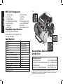
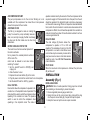
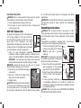
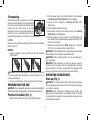
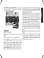
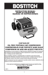
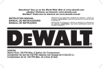
If you have questions or comments, contact us. Pour toute question ou tout commentaire, nous contacter. Si tiene dudas o comentarios, contáctenos. 1-800-4-DeWALT • www.dewalt.com Instruction Manual Guide D'utilisation Manual de instrucciones INSTRUCTIVO DE OPERACIÓN, CENTROS DE SERVICIO Y PÓLIZA DE GARANTÍA. ADVERTENCIA: LÉASE ESTE INSTRUCTIVO ANTES DE USAR EL PRODUCTO. D55371 Portable Air Compressor with sealed lube pump Compresseur d’air portatif avec la pompe scellée et lubrifiée Compresor de aire con la bomba sellada de lubricación English D55371 Air Compressor A.Sliding Handles B.Drain Valve C.Storage Support D.Regulated Pressure Gauge E.Quick Connects F.Regulator G.Safety Valve FIG. 1 C H. Pressure Switch I.Cord Wrap J.Air Filter K.Tank Pressure Gauge L.Auto(–)/Off(O) Switch M.Pilot Valve N.Dual Voltage Control J K F D i E Pump/Motor Specifications Voltage: Single Phase 120V/240V Minimum branch circuit requirement: 15 A Fuse Type: Time delay N Specifications MODEL WEIGHT HEIGHT WIDTH Length Air Tank Capacity APPROX CUT-IN PRESSUre Approx. CUT-OUT pressure Approx. Pilot valve reset Approx. Pilot valve blow off SCFM @ 100 psi Noise Level *Tested per ISO 1217 +Tested per ISO 3744 L A D55371 128 lbs. (58 kg) 18.0" (457.2 mm) 24.0" (609.6 mm) 33.0" (838.2 mm) 7.5 Gallon (28.4 liters) 145 psi 175 psi 145 psi 160 psi 4.6 * 75 dBA + G H B M Declared Noise Emission Values per ISO 3744 Noise Emission Values Sound Pressure Level: LpA = 75.0 dBA re 20μPA Uncertainty in the Sound Pressure Level: KpA = 3.0 dBA re 20μPA Sound Power Level: Uncertainty in the Sound Power Level: 2 LwA = 88.5 dBA re 1 pw KwA = 3.0 dBA re 1 pw The sum of the emission value and the uncertainty is the limit below which there is a 95% confidence the value of a single tool will lie below when the tool is new. WARNING: Some dust contains chemicals known to the State of California to cause cancer, birth defects or other reproductive harm such as asbestos and lead in lead based paint. Definitions: Safety Guidelines Save these instructionS DANGER: Risk of explosion or fire What can happen How to prevent it • It is normal for electrical • Always operate the comprescontacts within the motor sor in a well ventilated area and pressure switch to free of combustible materials, spark. gasoline, or solvent vapors. • If electrical sparks from • If spraying flammable matecompressor come into conrials, locate compressor tact with flammable vapors, at least 20' (6.1 m) away they may ignite, causing fire from spray area. An addior explosion. tional length of hose may be required. • Store flammable materials in a secure location away from compressor. IF YOU HAVE ANY QUESTIONS OR COMMENTS ABOUT THIS OR ANY DeWALT TOOL, CALL US TOLL FREE AT: 1-800-4-DeWALT (1-800-433-9258) Important Safety Instructions WARNING: Do not operate this unit until you read and understand this instruction manual for safety, operation and maintenance instructions. WARNING: This product contains chemicals known to the State of California to cause cancer, and birth defects or other reproductive harm. Wash hands after handling. 3 English The definitions below describe the level of severity for each signal word. Please read the manual and pay attention to these symbols. DANGER: Indicates an imminently hazardous situa tion which, if not avoided, will result in death or serious injury. WARNING: Indicates a potentially hazardous situation which, if not avoided, could result in death or serious injury. CAUTION: Indicates a potentially hazardous situation which, if not avoided, may result in minor or moderate injury. NOTICE: Indicates a practice not related to personal injury which, if not avoided, may result in property damage. English • Restricting any of the com- • Never place objects against pressor ventilation openings or on top of compressor will cause serious overheatpump. ing and could cause fire. • Operate compressor in an open area at least 12" (30.5 cm) away from any wall or obstruction that would restrict the flow of fresh air to the ventilation openings. • Operate compressor in a clean, dry well ventilated area. Do not operate unit indoors or in any confined area. • Always remain in attendance • Unattended operation of with the product when it is this product could result in operating. personal injury or property damage. To reduce the • Always turn off and unplug risk of fire, do not allow unit when not in use. the compressor to operate unattended. DANGER: RISK TO BREATHING (Asphyxiation) What can happen How to prevent it • The compressed air directly • Never use air obtained directly from the compressor to supply from your compressor is not air for human consumption. safe for breathing. The air The compressor is not stream may contain carbon equipped with suitable filters monoxide, toxic vapors, and in-line safety equipment or solid particles from the for human consumption. air tank. Breathing these contaminants can cause serious injury or death. • Work in an area with good • Exposure to chemicals cross ventilation. Read and in dust created by follow the safety instructions power sanding, sawing, provided on the label or grinding, drilling, and other safety data sheets for the construction activities may materials you are spraying. be harmful. Always use certified safety • Sprayed materials such as equipment: NIOSH/OSHA paint, paint solvents, paint respiratory protection or remover, insecticides, weed properly fitting face mask killers, may contain harmful designed for use with your vapors and poisons. specific application. 4 • Modifications or attempted repairs to the air tank. What can happen • Failure to properly drain condensed water from air tank, causing rust and thinning of the steel air tank. • Unauthorized modifications to the safety valve or any other components which control air tank pressure. Attachments & Accessories: • Follow the equipment manu• Exceeding the pressure facturers recommendation rating of air tools, spray guns, and never exceed the maxiair operated accessories, mum allowable pressure rattires, and other inflatables ing of attachments. Never can cause them to explode use compressor to inflate or fly apart, and could result small low pressure objects in serious injury. such as children’s toys, footballs, basketballs, etc. How to prevent it • Drain air tank daily or after each use. If air tank develops a leak, replace it immediately with a new air tank or replace the entire compressor. 5 English WARNING: RISK of Bursting Air Tank: On February 26, 2002, the U.S. Consumer Product Safety Commission published Release # 02-108 concerning air compressor tank safety: Air compressor receiver tanks do not have an infinite life. Tank life is dependent upon several factors, some of which include operating conditions, ambient conditions, proper installations, field modifications, and the level of maintenance. The exact effect of these factors on air receiver life is difficult to predict. If proper maintenance procedures are not followed, internal corrosion to the inner wall of the air receiver tank can cause the air tank to unexpectedly rupture allowing pressurized air to suddenly and forcefully escape, posing risk of injury to consumers. Your compressor air tank must be removed from service by the end of the year shown on your tank warning label. The following conditions could lead to a weakening of the air tank, and result in a violent air tank explosion: • Never drill into, weld, or make any modifications to the air tank or its attachments. Never attempt to repair a damaged or leaking air tank. Replace with a new air tank. • The air tank is designed to withstand specific operating pressures. Never make adjustments or parts substitutions to alter the factory set operating pressures. English Tires: • Over inflation of tires could result in serious injury and property damage. • Repairs attempted by unqualified personnel can result in serious injury or death by electrocution. • Any electrical wiring or repairs required on this product should be performed by a DeWALT factory service center or a DeWALT authorized service center in accordance with national and local electrical codes. • Make certain that the • Electrical Grounding: electrical circuit to which the Failure to provide adequate compressor is connected grounding to this product provides proper electrical could result in serious injury grounding, correct voltage or death from electrocution. and adequate fuse protection. See Grounding Instructions under Installation. • Use a tire pressure gauge to check the tires pressure before each use and while inflating tires; see the tire sidewall for the correct tire pressure. NOTE: Air tanks, compressors and similar equipment used to inflate tires can fill small tires very rapidly. Adjust pressure regulator on air supply to no more than the rating of the tire pressure. Add air in small increments and frequently use the tire gauge to prevent over inflation. WARNING: Risk of Electrical Shock What can happen • Your air compressor is powered by electricity. Like any other electrically powered device, If it is not used properly it may cause electric shock. WARNING: Risk from Flying Objects How to prevent it • Never operate the compressor outdoors when it is raining or in wet conditions. • Never operate compressor with protective covers removed or damaged. What can happen How to prevent it • The compressed air stream • Always wear certified safety equipment: ANSI Z87.1 eye can cause soft tissue protection (CAN/CSA Z94.3) damage to exposed skin and with side shields when using can propel dirt, chips, loose the compressor. particles, and small objects at high speed, resulting in • Never point any nozzle or property damage or personal sprayer toward any part of injury. the body or at other people or animals. 6 WARNING: Risk from Moving Parts What can happen How to prevent it • Moving parts such as the • Never operate the compressor pulley, flywheel, and belt can with guards or covers which cause serious injury if they are damaged or removed. come into contact with you or • Keep your hair, clothing, and your clothing. gloves away from moving parts. Loose clothes, jewelry, or long hair can be caught in moving parts. • Air vents may cover moving parts and should be avoided as well. • Any repairs required on this • Attempting to operate product should be performed compressor with damaged or by a DeWALT factory missing parts or attempting to repair compressor with service center or a DeWALT protective shrouds removed authorized service center. can expose you to moving parts and can result in serious injury. WARNING: RISK OF Hot surfaces What can happen How to prevent it • Touching exposed metal • Never touch any exposed such as the compressor metal parts on compressor head, engine head, engine during or immediately after operation. Compressor will exhaust or outlet tubes, can result in serious burns. remain hot for several minutes after operation. • Do not reach around protective shrouds or attempt maintenance until unit has been allowed to cool. 7 English • Always turn the compressor off and bleed pressure from the air hose and air tank before attempting maintenance, attaching tools or accessories. English WARNING: RISK OF FALLING What can happen How to prevent it • Always operate compressor • A portable compressor in a stable secure position to can fall from a table, prevent accidental movement workbench, or roof causing of the unit. Never operate damage to the compressor compressor on a roof or and could result in serious other elevated position. Use injury or death to the additional air hose to reach operator. high locations. WARNING: Risk of Unsafe Operation What can happen How to prevent it • Unsafe operation of your air • Review and understand all compressor could lead to seri instructions and warnings in ous injury or death to you or this manual. others. • Become familiar with the operation and controls of the air compressor. • Keep operating area clear of all persons, pets, and obstacles. • Keep children away from the air compressor at all times. • Do not operate the product when fatigued or under the influence of alcohol or drugs. Stay alert at all times. • Never defeat the safety fea tures of this product. • Equip area of operation with a fire extinguisher. • Do not operate machine with missing, broken, or unautho rized parts. • Never stand on the compressor. WARNING: RISK OF INJURY FROM LIFTING What can happen • Serious injury can result from attempting to lift too heavy an object. How to prevent it • The compressor is too heavy to be lifted by one person. Obtain assistance from others before lifting. CAUTION: risk from noise What can happen How to prevent it • Under some conditions and • Always wear certified safety duration of use, noise from equipment: ANSI S12.6 this product may contribute (S3.19) hearing protection. to hearing loss. 8 SAVE THESE INSTRUCTIONS FOR FUTURE USE Features (Fig. 1) Tank Pressure Gauge The tank pressure gauge (K) indicates the reserve air pressure in the tank. Auto(–)/Off(o) Switch Place this switch (L) in the AUTO(–) position to provide automatic power to the pressure switch and OFF(O) to remove power at the end of each use. NOTE: ALWAYS ensure the switch (L) is in the OFF(O) position before removing or replacing pressure switch cover. REGULATED Pressure K F D Gauge The regulated pressure gauge (D) indicates the air pressure available at the outlet side of the regulator. This pressure is controlled by the regulator and is always less than or equal to the tank pressure. L Regulator The regulator (F) controls the air pressure shown on the regulated pressure gauge. Pull the knob out and turn clockwise to increase pressure and counterclockwise to decrease pressure. When the desired pressure is reached push knob in to lock in place. Pressure Switch The pressure switch (H) automatically starts the motor when the air tank pressure drops below the factory set cut-in pressure. It stops the motor when the air tank pressure reaches the factory set cut-out pressure. Safety Valve If the pressure switch does not shut off the air compressor at its cut-out pressure setting, the safety valve (G) will protect against high pressure by popping out at its factory set pressure (slightly higher than the pressure switch cut-out setting). Universal Quick Connect BodIES The universal quick connect body (E) accepts the three most popular styles of quick connect plugs: Industrial, automotive, and ARO. One hand push-to-connect operation makes connections simple and easy. The two quick connect bodies allow the use of two tools at the same time. Drain Valve The drain valve (B) is located at the base of the air tank and is used to drain condensation at the end of each use. See Draining Air Tank under Maintenance. G Check Valve When the air compressor is operating, the check valve is open, allowing compressed air to enter the air tank. When the air compressor reaches cut-out pressure, the check valve closes, allowing air pressure to remain inside the air tank. B Cooling System This compressor contains an advanced design cooling system. It is normal for this fan to blow air through the vent holes in large amounts. The cooling system is working when air is expelled. 9 English H E English Air Compressor Pump The pump compresses air into the air tank. Working air is not available until the compressor has raised the air tank pressure above that required at the air outlet. AIR INTAKE FILTER The filter (J) is designed to clean air entering the pump. To ensure the pump continually receives a clean, cool, and dry air supply the filter must always be clean and the filter intake must be free from obstructions. operation is determined by the amount of time the compressor will be required to supply air. If the demand for air is infrequent, then the unit should be operated in the stop/start mode to minimize unnecessary run time and to save energy. If there is a frequent or extended demand for air, and/or the unit is located in a remote area where access to the compressor is difficult, the unit should be operated in the constant run mode to minimize the number of times the motor must start in an hour to ensure good motor life. DUAL voltage The dual voltage (N) feature allows the compressor to operate in 115 or 230 volt operation. The advantage of running in the 230 volt operation is a lower current draw. Lower current draw may be necessary in areas with a poor power source. Lower current also reduces operating costs. See 230 Volt Conversion under Installation. J Motor Overload Protector The motor has a thermal overload protector. If r the motor overheats for any reason, the overload protector will shut off the motor. The motor must be allowed to cool down before restarting. To restart: 1.Set the Auto/Off switch to OFF(O) and unplug unit. 2.Allow the motor to cool. 3.Depress the red reset button (R) on the motor. 4.Plug the power cord into the correct branch circuit receptacle. 5.Set the Auto/Off switch to Auto(–) position. DUAL CONTROL M Dual control allows the compressor to operate in the constant run or the stop/start mode of operation. The pilot valve (M) is used to control the compressor when operating in the constant run mode. The pressure switch is used to control the compressor when operating in the stop/start mode. The mode of N Pilot Valve When the maximum air tank pressure is obtained, the pilot valve (M) will blow-off. INSTALLATION Assembly (Fig. 1) Installing Hoses Warning: Risk of unsafe operation. Firmly grasp hose in hand when installing or disconnecting to prevent hose whip. 1.Ensure regulated pressure gauge reads 0 psi. 2.Grasp the hose at the quick connect plug and push the plug into the quick connect body (E). Coupler will snap into place. 3.Grasp the hose and pull to ensure coupler is seated. 10 for 115 volts and the rated amps of the compressor, See Motor Specifications. WARNING: Do not operate this unit until you read and understand this instruction manual for safety, operation and maintenance instructions. Grounding Instructions 230 Volt Conversion Warning: Risk of electrical shock. In the event of a short circuit, grounding reduces the risk of shock by providing an escape wire for the electric current. This air compressor must be properly grounded. The portable air compressor is equipped with a cord having a grounding wire with an appropriate grounding plug. 1.The cord set and plug (P) with this unit 115V contains a grounding pin (Q). This plug P MUST be used with a grounded O outlet (O). IMPORTANT: The outlet being used must be installed and grounded in accordance Q with all local codes and ordinances. 2.Ensure the outlet being used has the 230V same configuration as the grounded O plug. DO NOT USE AN ADAPTER. P 3.Inspect the plug and cord before each use. Do not use if there are signs of damage. Q 4.If these grounding instructions are not completely understood, or if in doubt as to whether the compressor is properly grounded, have the installation checked by a qualified electrician. danger: Risk of electrical shock. IMPROPER GROUNDING CAN RESULT IN ELECTRICAL SHOCK. To operate the compressor at 230 volts replace the 115 volt plug supplied on the motor cord with a UL/ CSA listed plug suitable for 230 volts and the rated amps of the compressor, see Motor Specifications at the beginning of this manual. A 230 volt plug as shown in the diagram may be purchased at a local hardware or electrical supply store. 1.Follow the plug manufacturer installation procedures, contact a qualified electrician, a DeWALT service center or call 1‑800‑4‑DeWALT (1-800-433-9258) for assistance. IMPORTANT: The compressor must comply with all local and national electrical codes after the 230 volt plug is installed. WARNING: Ensure the 230 volt cord plug end is properly connected before operating in 230 volt mode. 2.Remove the pin on the 115/230 dual voltage N control switch. 3.Move the 115/230 dual voltage control switch (N) to the 230 volt position. 4.Replace the pin. CAUTION: Once the unit has been converted to 230 volts the 115/230 dual control switch can not be placed in the 115 volt position until the cord plug is replaced with a UL/CSA listed cord plug suitable 11 English Disconnecting Hoses Warning: Risk of unsafe operation. Firmly grasp hose in hand when installing or disconnecting to prevent hose whip. 1.Ensure regulated pressure gauge reads 0 psi. 2.Push coupler on quick connect body back to release quick connect plug on hose. English • Do not modify the plug provided. If it does not fit the available outlet, a correct outlet should be installed by a qualified electrician. • Repairs to the cord set or plug MUST be made by a qualified electrician. time delay fuse. NOTE: If compressor is connected to a circuit protected by fuses, use only time delay fuses. Time delay fuses should be marked “D” in Canada and “T” in the U.S. If any of the above conditions cannot be met, or if operation of the compressor repeatedly causes interruption of the power, it may be necessary to operate it from a 20 amp circuit. It is not necessary to change the cord set. Extension Cords If an extension cord must be used, be sure it is: • a 3-wire extension cord that has a 3-blade grounding plug, and a 3-slot receptacle that will accept the plug on the product • in good condition • plug is not worn • no longer than 50' (15.2 m) • 12 gauge (AWG) or larger. (Wire size increases as gauge number decreases. 10 AWG and 8 AWG may also be used. DO NOT USE 14 OR 16 AWG.) NOTICE: The use of an undersized extension cord will cause volt age to drop resulting in power loss to the motor and overheating. Instead of using an extension cord, increase the working reach of the air hose by attaching another length of hose to its end. Attach additional lengths of hose as needed. Always use a minimum 3/8" (9.5 mm) or greater air hose rated at 300 psi. Compatibility NOTE: Always use an air line filter to remove moisture and oil vapor when spraying paint. Location Place the air compressor in a clean, dry and well ventilated area at least 12" (30.5 cm) away from the wall or other obstructions that will interfere with the flow of air. Keep the compressor away from areas that have dirt and/or volatile fumes in the atmosphere. These impurities may clog the intake filter and valves, causing inefficient operation. Warning: The air compressor pump and shroud are designed to allow for proper cooling. The ventilation openings on the com pressor are necessary to maintain proper operating temperature. Do not place rags or other containers on or near these openings. Place the air compressor on a flat surface resting on the wheels and rubber foot. Voltage and Circuit Protection Refer to the Voltage and Minimum Branch Circuit Requirements under Specifications. CAUTION: Certain air compressors can be operated on a 15 amp circuit if the following conditions are met. • Voltage supply to circuit must comply with the National Electrical Code. • Circuit is not used to supply any other electrical needs. • Extension cords comply with specifications. • Circuit is equipped with a 15 amp circuit breaker or 15 amp Electrical Refer to all safety instructions before using unit. Observe extension cord safety instructions, if necessary. Always move the Auto/Off switch (L) to the OFF(O) position before removing the plug from the outlet. 12 Transporting Lifting Always use two people when lifting and lift from the recommended lift points A and C. MOVING 1.Support compressor and pull handle (A) until fully extended (lock position). A A Warning: Risk of unsafe operation. Ensure proper footing and use caution when rolling compressor so that unit does not tip or cause loss of balance. 2. To move, roll compressor on tires using handle (A) as shown. Operating Procedures Start-up (Fig. 1) Warning: Hot surfaces. Risk of burn. Aftercooler, pump head, and surrounding parts are very hot, do not touch. Allow compressor to cool prior to servicing. Warning: Risk of moving parts. Keep your hair, clothing, and gloves away from moving parts. Loose clothes, jewelry or long hair can be caught in moving parts. Air vents may cover moving parts and should be avoided as well. Preparation For Use WARNING: Do not operate this unit until you read and understand this instruction manual for safety, operation and maintenance instructions. Pre-Start Checklist (Fig. 1) 1.Ensure the Auto/Off switch (L) is in the OFF(O) position. 13 English 2.Plug the power cord into the correct branch circuit receptacle. See Voltage and Circuit Protection under Installation. 3.Ensure air tank is drained, see Draining Air Tank under Maintenance. 4.Ensure the drain valve (B) is closed. 5.Ensure safety valve (G) is functioning properly, see Checking Safety Valve under Maintenance. 6.Pull the regulator knob (F) out and turn counterclockwise until fully closed. Ensure regulated pressure gauge reads 0 psi. Push knob in to lock in place. 7.Attach hose and accessories. NOTE: Always use a minimum 3/8" (9.5 mm) or greater air hose rated at 300 psi. Warning: Risk of unsafe operation. Firmly grasp air hose in hand when installing or disconnecting to prevent hose whip. Warning: Risk of unsafe operation. Do not use damaged or worn accessories. Warning: Risk of Bursting. Too much air pressure causes a hazardous risk of bursting. Check the manufacturer’s maximum pressure rating for air tools and accessories. The regulator outlet pressure must never exceed the maximum pressure rating. When transporting the compressor in a vehicle, C trailer, etc. ensure that the air tank is drained and the unit is secured and placed on a flat horizontal surface. Use care when driving so to avoid tipping the unit over in the vehicle. Damage can occur to the unit or surrounding items if unit is A tipped. Store compressor in a vertical or horzitional position. English the pump head. If compressor shuts off, contact a DeWALT service center or call 1‑800‑4‑DeWALT (1-800-433-9258) for assistance. Note: For proper operation the pilot valve blow-off pressure must be below the pressure switch cut out pressure. 4.Adjust regulator (F) to desired setting. See Regulator under Features. CAUTION: Risk of unsafe operation. Do not operate in vertical position. Vertical position is for storage only. CAUTION: Risk of unsafe operation. Compressed air from the unit may contain water condensation and oil mist. Do not spray unfil tered air at an item that could be damaged by moisture. Some air operated tools or devices may require filtered air. Read the instruc tions for the air tool or device 1.Follow Pre-Start Checklist under Preparation for Use. 2.Move the Auto/Off switch to the AUTO(–) position. 3.Select Stop Start Mode or Constant Run Mode. See Dual Control under Features for description: Shut-down (Fig. 1) 1.Move Auto/Off switch (L) to the OFF(O) position. NOTE: If finished using compressor, follow Steps 2–6. NOTE: If operating in the constant run mode turn pilot valve knob clockwise until it stops before moving the Auto/Off switch (L) to the OFF(O) position. 2.Pull the regulator knob (F) out and turn counterclockwise until fully closed. Ensure regulated pressure gauge reads 0 psi. Push knob in to lock in place. 3.Remove hose and accessory. Warning: Risk of unsafe operation. Firmly grasp air hose in hand when installing or disconnecting to prevent hose whip. 4.Drain the air tank, see Draining Air Tank under Maintenance. Ensure air tank pressure gauge reads 0 psi. Warning: Risk of bursting. Drain air tank daily. Water will condense in air tank. If not drained, water will corrode and weaken the air tank causing a risk of air tank rupture. 5.Allow the compressor to cool down. 6.Wipe air compressor clean and store in a safe, non-freezing area. Stop Start Mode a.Turn knob on top of pilot valve (M) clockwise until fully closed. Warning: Risk of property damage. Over tightening the Pilot Valve knob can cause damage to the pilot valve. b.Allow compressor to reach cut-out pressure. If compressor does not stop, contact a DeWALT service center or call 1‑800‑4‑DeWALT (1-800-433-9258) for assistance. Constant Run Mode a. Turn knob on top of pilot valve (M) fully counterclockwise until fully open. Warning: Risk of property damage. Over loosening the pilot valve knob can cause damage to the pilot valve. b.The compressor is now in constant run mode. NOTE: After the compressor reaches blow-off pressure the unit will continue to run but will not build additional tank pressure until the air is used and the pilot valve reset pressure is reached. A slight air noise may be heard while the air is being unloaded through Maintenance The following procedures must be followed when maintenance or service is performed on the air compressor. 1.Ensure Auto/Off (L) switch is in the OFF(O) position. 2.Remove air compressor plug from outlet. 14 Warning: Risk from flying objects. Always wear certified safety equipment: ANSI Z87.1 eye protection (CAN/CSA Z94.3) with side shields when using the compressor. Before starting compressor, pull the ring on the safety valve to make sure that the safety valve operates freely. NOTE: Ring may be difficult to pull when air tank pressure is at 0 psi. If the valve is stuck or does not operate smoothly, it must be replaced with the same type of valve. Draining Air Tank (Fig. 1) Warning: Risk of unsafe operation. Risk from noise. Air tanks contain high pressure air. Keep face and other body parts away from outlet of drain. Use eye protection [ANSI Z87.1 (CAN/CSA Z94.3)] when draining as debris can be kicked up into face. Warning: Risk from noise. Use ear protection [ANSI S12.6 (S3.19)] as air flow noise is loud when draining. NOTE: All compressed air systems generate condensate that accumulates in any drain point (e.g. tanks, filter, aftercoolers, dryers). This condensate contains lubricating oil and/or substances which may be regulated and must be disposed of in accordance with local, state, and federal laws and regulations. 1.Ensure Auto/Off switch is in the OFF(O) position. 2.Lift compressor into an inclined position so drain valve (B) is at the lowest point (this will assist in removing moisture, dirt, etc. from air tanks). 3.Place a suitable container under the drain valve to catch discharge. 4.Grasp lever on drain valve. 5.Slowly rotate lever to gradually bleed air from air tank. Warning: Risk of bursting. Drain air tank daily. Water will con dense in air tank. If not drained, water will corrode and weaken the air tank causing a risk of air tank rupture. Maintenance Chart Procedure Check safety valve Daily See tank warning label X Inspect air filter Drain air tank Weekly X X Check for unusual noise/vibration X Check for air leaks X1 Clean compressor exterior X Remove tank from service X2 1 - To check for air leaks apply a solution of soapy water around joints. While compressor is pumping to pressure and after pressure cuts out, look for air bubbles to form. 2 - For more information, call 1-800-4-DeWALT (1-800-433-9258) Checking Safety Valve (Fig. 1) Warning: Risk of bursting. If the safety valve does not work properly, over-pressurization may occur, causing air tank rupture or an explosion. 15 English 3.Drain air tank. 4.Allow air compressor to cool down before starting service. NOTE: All compressed air systems contain maintenance parts (e.g., oil, filters, separators) that are periodically replaced. These used parts may contain substances that are regulated and must be disposed of in accordance with local, state, and federal laws and regulations. NOTE: Take note of the positions and locations of parts during disassembly to make reassembly easier. NOTE: Any service operations not included in this section should be performed by a DeWALT factory service center or a DeWALT authorized service center. English Service Information NOTICE: Risk of property damage. Drain water from air tank may contain oil and rust, which can cause stains. 6. When air tank pressure gauge reads 10 psi, rotate valve to the fully open position. 7.Close drain valve when finished. Please have the following information available for all service calls: Model Number ____________ Serial Number _________________ Date and Place of Purchase ______________________________ Repairs Checking Air Filter Element (Fig. 1) To assure product SAFETY and RELIABILITY, repairs, maintenance and adjustment should be performed by a DeWALT factory service center, a DeWALT authorized service center or other qualified service personnel. Always use identical replacement parts. Warning: Hot surfaces. Risk of burn. Outlet tube, pump head, and surrounding parts are very hot, do not touch. Allow compressor to cool prior to servicing. 1.Ensure Auto/Off switch (L) is in the OFF(O) Position. 2.Allow unit to cool. 3.Remove filter cover (J) from filter base. 4.Remove element from filter base. 5.Place new element back in filter base. Purchase replacement parts from your local dealer or J authorized service center. Always use identical replacement parts. 6.Snap filter cover to filter base. NOTICE: Risk of property damage. Do not operate without air inlet filter Full One Year Warranty DeWalt heavy duty industrial tools are warranted for one year from date of purchase. We will repair, without charge, any defects due to faulty materials or workmanship. For warranty repair information, call 1-800-4-DeWALT (1-800-433-9258). This warranty does not apply to accessories or damage caused where repairs have been made or attempted by others. This warranty gives you specific legal rights and you may have other rights which vary in certain states or provinces. Latin America: This warranty does not apply to products sold in Latin America. For products sold in Latin America, see country specific warranty information contained either in the packaging, call the local company or see website for warranty information. Accessories Warning: The use of any other accessory not recommended for use with this tool could be hazardous. Use only accessories rated equal to or higher than the rating of the air compressor. Recommended accessories for use with your tool are available for purchase from your local dealer or authorized service center. If you need assistance in locating any accessory for your tool, please contact DeWALT Industrial Tool Co., 701 East Joppa Road, Baltimore, MD 21286, call 1-800-4-DeWALT (1-800-433-9258) or visit our website www.dewalt.com. 16 TANK DAILY OR AFTER EVERY 4 HOURS OF US E. CONDENSATION BUILD-UP MAY CAUSE WARNING DRAIN CORROSION INSIDE TANK RESULTING IN TANK FAILURE. SEE MANUAL FOR INSPECTION PROCEDURES. TO D RAIN TANK OPEN VALVE SLOWLY AND TILT COMPRESSOR TO EMPTY ACCUMULATED WATER. DRENE ELTANQUE A DIARIO O DESPUÉS DE CADA 4 HO RAS DE USO. LA ACUMULACIÓN DE ADVERTENCIA CONDENSACIÓN PUEDE O CASIONAR CORROSIÓN DENTRO DEL TANQUE Y PROVO CAR FALLA DEL TANQU E. CONSULTE EL MANUAL PARA CONOCER LOS PROCEDIMIENTOS DE INSPECCIÓN. PARA DRENAR EL TANQU E, ABRA LA VÁLVULA LENTAMENTE E INCLINE EL COMPRESOR PARAELIMINAR EL AGUA ACUMULADA. RÉSE RVOIR DE VIDANGE QU OTIDIEN OU APRÈS TOUTES LES 4 HEURES D'UTILISATION. AVERTISSEMENT L'HABILLAGE DE CONDENSATION PEUT CAUSER LA CORROSION À L'INTÉRIEUR DU RÉSERVOIR AYANT POUR RÉSULTAT L'ÉCHEC DE RÉSERVOIR. VOIR LE MANUEL POUR DES PROCÉDURES D'INSPECTION. À LA VALVE OUVERTE DE RÉSERVOIR DE VIDANGE LENTEMENT ET AU COMPRESSEUR D'INCLINAISON ÀL'EAU ACCUMULÉE VIDE. ATTENTION DO NOT OPERATE IN UPRIGHT POSITION. UPRIGHT POSITION IS FOR STORAGE ONLY. NO OPERE LA HERRAMIENTA EN POSICIÓN VERTICAL. SÓLO ALMACENE EN ESTA POSICIÓN. NE PAS FAIRE FONCTIONNER EN POSITION VERTICALE. LA POSITION VERTICALE EST RÉSERVÉE AU STOCKAGE UNIQUEMENT. WARNING HOT SURFACES ADVERTENCIA SUPERFICIES CALIENTES AVERTISSEMENT SURFACES CHAUDES WARNING DO N OT ADJUST FACTORY SETTINGS. TO REDUCE RISK OF ELE CTRIC SHOCK DO N OT REMOVE COVER. Pressure controls set at factory for maximum sa fe ope ration. ADVERTENCIA NO HAGA CAMBIOS ENLOS AJUSTES DE FÁBRICA. NO RETIRE LA TAPA PARA REDUCIR EL RIESGO DE CHOQUE ELÉ CTRICO. Los controles de presión se ajustan en la fábrica para máxima segu ridad en la ope ración. AVERTISSEMENT Glossary CFM: Cubic feet per minute. Duty Cycle: This air compressor pump is capable of running continuously. However, to prolong the life of your air compressor, it is recommended that a 50%-75% average duty cycle be maintained; that is, the air compressor pump should not run more than 30-45 minutes in any given hour. SCFM: Standard cubic feet per minute; a unit of measure of air delivery. PSI: Pounds per square inch; a unit of measure of pressure. Code Certification: Products that bear one or more of the following marks: UL®*, CUL, ETL®*, CETL, have been evaluated by OSHA certified independent safety laboratories and meet the applicable Standards for Safety. *UL® is a registered trademark of Underwriters Laboratories and ETL® is a registered trademark of Electrical Testing Laboratories. Pilot Valve Blow-Off Pressure: Continuous running units are controlled by air tank pressure. When the maximum air tank pressure 17 English is obtained, the pilot valve will blow-off. This decreases the load on the motor and allows it to run at a near no-load condition. Note: For proper operation the pilot valve blow-off pressure must be below the pressure switch cut-out pressure. Pilot Valve Reset Pressure: When the air tank pressure drops to a predetermined point, the pilot valve closes. The air tank pressure will now increase until it reaches the pilot valve blow-off pressure. Cut-In Pressure: While the motor is off, air tank pressure drops when accessory is used. When the tank pressure drops to a certain low level the motor will restart automatically. The low pressure at which the motor automatically restarts is called cut-in pressure. Cut-Out Pressure: When an air compressor is turned on and begins to run, air pressure in the air tank begins to build. It builds to a certain high pressure before the motor automatically shuts off, protecting your air tank from pressure higher than its capacity. The high pressure at which the motor shuts off is called cut-out pressure. Branch Circuit: The circuit carrying electricity from electrical panel to outlet. FREE WARNING LABEL REPLACEMENT: If your warning labels become illegible or are missing, call 1-800-4-DeWALT (1-800-433-9258) for a free replacement. English Troubleshooting Guide This section provides a list of the more frequently encountered malfunctions, their causes and corrective actions. The operator or maintenance personnel can perform some corrective actions, and others may require the assistance of a qualified DeWalt technician or your dealer. Problem Code Excessive air tank pressure-safety valve pops off .......................................................................1, 2 Air leaks . ................................................................................................................................... 3 Air leaks in air tank or at air tank welds..................................................................................... 4 Air leaks between head and valve plate..................................................................................... 5 Air leaks from safety valve.......................................................................................................... 6 Knocking Noise........................................................................................................................... 11 Pressure reading on the regulated pressure gauge drops when an accessory is used............ 7 Compressor is not supplying enough air to operate accessories.............................................. 8, 9, 10, 11, 12, 21, 23 Regulator knob has continuous air leak..................................................................................... 13 Regulator will not shut off air outlet............................................................................................ 13 Motor will not run........................................................................................................................ 11, 14, 15, 16, 17, 18, 19, 20, 24 Motor shuts off when operating in constant run mode............................................................... 22, 25 Continuous air leak at pressure relief tube................................................................................. 26, 27 Troubleshooting Codes Code possible cause POSSIBLE SOLUTION 1 Pressure switch does not shut off motor when compressor reaches cut-out pressure Pilot valve does not release pressure when air tank reaches blow-off pressure Set the Auto/Off switch to OFF(O), if the unit does not shut off contact a DeWALT factory service center or a DeWALT authorized service center. Pilot valve must be replaced. 2 Pressure switch cut-out too high Contact a DeWALT factory service center or a DeWALT authorized service center. 3 Tube fittings are not tight enough Tighten fittings where air can be heard escaping. Check fittings with soapy water solution. Do Not Overtighten. 18 Code POSSIBLE SOLUTION 4 Defective air tank Air tank must be replaced. Do not repair the leak. Warning: Risk of bursting. Do not drill into, weld or otherwise modify air tank or it will weaken. The air tank can rupture or explode. 5 Leaking seals Contact a DeWALT factory service center or a DeWALT authorized service center. 6 Defective safety valve Operate safety valve manually by pulling on ring. If valve still leaks, it must be replaced. 7 Regulator is not adjusted correctly for accessory being used It is normal for some pressure drop to occur when an accessory is used, adjust the regulator as instructed in Regulator under Features if pressure drop is excessive. NOTE: Adjust the regulated pressure under flow conditions while accessory is being used. 8 Prolonged excessive use of air Decrease amount of air usage. 9 Compressor is not large enough for accessory Check the accessory air requirement. If it is higher than the CFM or pressure supplied by your air compressor, a larger compressor is needed to operate accessory. 10 Hole in air hose Replace air hose. 11 Check valve restricted Remove, clean or replace. 12 Air leaks Tighten fittings. 13 Regulator is damaged Replace. 14 Motor overload protection switch has tripped Refer to Motor Overload Protection under Features. If motor overload protection trips frequently, contact a DeWALT factory service center or a DeWALT authorized service center. 19 English possible cause English Code possible cause POSSIBLE SOLUTION 15 Tank pressure exceeds pressure switch cut-in pressure Motor will start automatically when tank pressure drops below cut-in pressure of pressure switch. 16 Extension cord is wrong length or gauge Check for proper gauge wire and cord length. Refer to the Extension Cords paragraph in the Installation section. 17 Loose electrical connections Contact a DeWALT factory service center or a DeWALT authorized service center. 18 Possible defective motor Contact a DeWALT factory service center or a DeWALT authorized service center. 19 Paint spray on internal motor parts Contact a DeWALT factory service center or a DeWALT authorized service center. Do not operate the compressor in the paint spray area. See flammable vapor warning. 20 Fuse blown, circuit breaker tripped 1.Check fuse box for blown fuse and replace as necessary. Reset circuit breaker. Do not use a fuse or circuit breaker with higher rating than that specified for our particular branch circuit. 2.Check for proper fuse. You should use a time delay fuse. 3.Check for low voltage conditions and/or proper extension cord. 4.Disconnect the other electrical appliances from circuit or operate the compressor on its own branch circuit. 21 Restricted air intake filter Clean or replace air intake filter. Do not operate the air compressor with the filter removed. Refer to the Air Filter paragraph in the Maintenance section. 22 Defective pilot valve Replace pilot valve. Contact a DeWALT factory service center or a DeWALT authorized service center. 20 possible cause POSSIBLE SOLUTION 23 Pilot valve restricted Remove, clean or replace. Contact a DeWALT factory service center or a DeWALT authorized service center. 24 Pilot valve knob is in the open position Turn pilot valve knob clockwise until it stops. 25 Defective pressure switch Replace pressure switch. Contact a DeWALT factory service center or a DeWALT authorized service center. 26 Defective check valve Replace check valve. Contact a DeWALT factory service center or a DeWALT authorized service center. 27 Defective pressure relief tube Replace pressure relief tube. Contact a DeWALT factory service center or a DeWALT authorized service center. 21 English Code