1
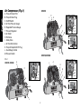
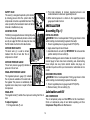
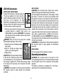
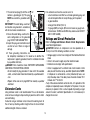
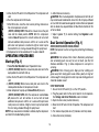
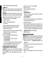
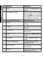
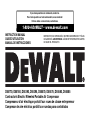
If you have questions or comments, contact us.
Pour toute question ou tout commentaire, nous contacter.
Si tiene dudas o comentarios, contáctenos.
1-800-4-DEWALT • www.dewalt.com
INSTRUCTION MANUAL
GUIDE D'UTILISATION
MANUAL DE INSTRUCCIONES
INSTRUCTIVO DE OPERACIÓN, CENTROS DE SERVICIO Y PÓLIZA
DE GARANTÍA. ADVERTENCIA: LÉASE ESTE INSTRUCTIVO ANTES
DE USAR EL PRODUCTO.
D55170, D55180, D55390, D55395, D55570, D55575, D55580, D55585
Contractor’s Electric Wheeled Portable Air Compressor
Compresseur d’air électrique portatif sur roues de classe entrepreneur
Compresor de aire eléctrico portátil con ruedas para contratistas
English
Air Compressor (Fig.1)
D55390
A. Pump Air Intake Filter
B. Pump Oil Drain Plug
C. On/Off Switch
D. Air Tank Pressure Gauge
E. Regulated Pressure Gauge
F. Pressure Regulator
G. Air Outlet
H. Pilot Valve
I. Safety Valve
J. Air Tank Drain Valves
K. Pump Oil Dipstick/Oil Fill Plug
L. Dual Voltage Control
M. Pressure Switch
L
K
A
D
B
F
E
G
F
M
M
H
C
I
J
D55570, D55580
FIG. 1
D55170, D55180
A
A
L
C
D
K
D
B
E
G
F
K
F
M
M
H
H
E
G
F
I
C
I
B F
J
J
2
D55395
A
L
M
Pump Specifications
M
K
I
F
G
B
E
H
D
G PUMP
V - twin 4 cylinder
Single Stage
Oil Lubricated
Cast Iron crankcase cylinder, and head
Bore: 2.5" (63.5 mm)
Stroke: 2.375" (60.3 mm)
Weight: 69 lbs. (31.3 kg.)
Oil Capacity: 30 oz. (887 mL)
J
D55575, D55585
A
L
M
M
C
K
I
F
G
B
E
H
D
3
K
B
K
B
English
K PUMP
Inline, vertical twin cylinder
Single Stage
Oil Lubricated
Cast Iron crankcase cylinder, and head
Bore: 2.5" (63.5 mm)
Stroke: 2" (50.8 mm)
Weight: 47 lbs. ( 21.3 kg.)
Oil Capacity: 14 oz. (414 mL)
C
English
Specifications
AIR TANK
CAPACITY
(GALLONS)
APPROX.
SCFM
PILOT
APPROX.
@ 100
VALVE
BLOW OFF/
PSI PUMP MOTOR
RESET/
CUT-OUT
(689.5
CUT-IN
PRESSURE
kPa)
PRESSURE
45.0 in.
(1143.0 mm)
8 (30.3 liters)
105 PSI
(723.9 kPa)
125 PSI
(861.8 kPa)
6.5
K
1.5 HP
18.3 in.
(463.6 mm)
43.0 in.
(1092.2 mm)
8 (30.3 liters)
105 PSI
(723.9 kPa)
125 PSI
(861.8 kPa)
8.4
K
2 HP
26.3
(666.8 mm)
18.3 in.
(463.6 mm)
43.0 in.
(1092.2 mm)
8 (30.3 liters)
105 PSI
(723.9 kPa)
125 PSI
(861.8 kPa)
13.8
G
3 HP
254 lbs.
(115.2 kg.)
32.0 in.
(812.8 mm)
20.3 in.
(514.4 mm)
43.0 in.
17 (64.4 liters)
(1092.2 mm)
105 PSI
(723.9 kPa)
125 PSI
(861.8 kPa)
13.8
G
3 HP
D55570
168 lbs.
(76.2 kg.
23.5 in.
(596.9 mm)
18.25 in.
(463.6 mm)
43.0 in.
(1092.2 mm)
8 (30.3 liters)
105 PSI
(723.9 kPa)
125 PSI
(861.8 kPa)
6.5
K
1.5 HP
D55575
194 lbs.
(88.0 kg.)
29.8 in.
(755.7 mm)
20.3 in.
(514.4 mm)
43.0 in.
17 (64.4 liters)
(1092.2 mm)
105 PSI
(723.9 kPa)
125 PSI
(861.8 kPa)
6.5
K
1.5 HP
D55580
175 lbs.
(79.4 kg.)
23.5 in.
(596.9 mm)
18.3 in.
(463.6 mm)
43.0 in.
(1092.2 mm)
8 (30.3 liters)
105 PSI
(723.9 kPa)
125 PSI
(861.8 kPa)
8.4
K
2 HP
D55585
201 lbs.
(91.2 kg.)
29.8 in.
(755.7 mm)
20.3 in.
(514.4 mm)
43.0 in.
17 (64.4 liters)
(1092.2 mm)
105 PSI
(723.9 kPa)
125 PSI
(861.8 kPa)
8.4
K
2 HP
MODEL
WEIGHT
HEIGHT
WIDTH
D55170
168 lbs.
(76.2 kg.)
33.0 in.
(838.2 mm)
22.5 in.
(571.5 mm)
D55180
172 lbs.
(78.0 kg.)
23.5 in.
(596.9 mm)
D55390
231 lbs.
(104.8 kg.)
D55395
LENGTH
4
Hot Surfaces
MOTOR SPECIFICATIONS
FIG. 2
ELECTRIC
MOTOR
COMPRESSOR
CYLINDER &
HEAD
OUTLET TUBE
2 HP
115V, 20 A, 60 Hz
230V, 10 A, 60 Hz
Four pole, induction type,1725 RPM
Minimum branch circuit requirement: 20 A @ 115V
15 A @ 230V
Fuse Type: Time delay
3 HP
230V, 10 A, 60 Hz
Four pole, induction type,1725 RPM
Minimum branch circuit requirement: 15 A @ 230V
Fuse Type: Time delay
PUMP
CRANKCASE
ELECTRIC
MOTOR
COMPRESSOR
CYLINDER &
HEAD
OUTLET TUBE
PUMP
CRANKCASE
5
English
1.5 HP
115V, 15 A, 60Hz
230V, 8 A, 60 Hz
Four pole, induction type,1725 RPM
Minimum branch circuit requirement: 15 A @ 115V and 230V
Fuse Type: Time delay
• lead from lead-based paints
• crystalline silica from bricks and cement and other masonry
products
• arsenic and chromium from chemically-treated lumber
Your risk from these exposures varies, depending on how often
you do this type of work. To reduce your exposure to these chemicals: work in a well ventilated area, and work with approved safety
equipment, always wear OSHA/MSHA/NIOSH approved, properly
fitting face mask or respirator when using such tools.
When using air tools, basic safety precautions should always be followed to reduce the risk of of personal injury.
WARNING: This product contains chemicals, including lead,
known to the State of California to cause cancer, and birth
defects or other reproductive harm. Wash hands after handling.
English
Definitions: Safety Guidelines
The definitions below describe the level of severity
for each signal word. Please read the manual and
pay attention to these symbols.
DANGER: Indicates an imminently hazardous
situation which, if not avoided, will result in death
or serious injury.
WARNING: Indicates a potentially hazardous
situation which, if not avoided, could result in death
or serious injury.
CAUTION: Indicates a potentially hazardous
situation which, if not avoided, may result in minor
or moderate injury.
CAUTION: Used without the safety alert symbol
indicates a potentially hazardous situation which, if
not avoided, may result in property damage.
SAVE THESE INSTRUCTION
DANGER: RISK OF EXPLOSION OR FIRE
WHAT CAN HAPPEN
HOW TO PREVENT IT
• It is normal for electrical
• Always operate the comprescontacts within the motor
sor in a well ventilated area
and pressure switch to
free of combustible materials,
spark.
gasoline, or solvent vapors.
IF YOU HAVE ANY QUESTIONS OR COMMENTS ABOUT
THIS OR ANY DEWALT TOOL, CALL US TOLL FREE AT:
1-800-4-DEWALT (1-800-433-9258)
Important Safety Instructions
WARNING: Do not operate this unit until you read and understand
this instruction manual for safety, operation and maintenance
instructions.
WARNING: Some dust created by power sanding, sawing, grinding, drilling, and other construction activities contains chemicals
known (to the State of California) to cause cancer, birth defects or
other reproductive harm. Some example of these chemicals are:
6
• Restricting any of the compressor ventilation openings
will cause serious overheating and could cause fire.
• Unattended operation of
this product could result in
personal injury or property
damage. To reduce the risk
of fire, do not allow the
compressor to operate unattended.
• If spraying flammable materials, locate compressor
at least 20' (6.1 m) away
from spray area. An additional length of hose may be
required.
• Store flammable materials in
a secure location away from
compressor.
• Never place objects against
or on top of compressor.
• Operate compressor in
an open area at least 12"
(30.5 cm) away from any
wall or obstruction that would
restrict the flow of fresh air to
the ventilation openings.
• Operate compressor in a
clean, dry well ventilated area.
Do not operate unit indoors or
in any confined area.
• Always remain in attendance
with the product when it is
operating.
• Always turn off and unplug
unit when not in use.
DANGER: RISK TO BREATHING (ASPHYXIATION)
WHAT CAN HAPPEN
• The compressed air directly
from your compressor is not
safe for breathing. The air
stream may contain carbon
monoxide, toxic vapors
or solid particles from the
air tank. Breathing these
contaminant's can cause
serious injury or death.
• Sprayed materials such as
paint, paint solvents, paint
remover, insecticides and
weed killers, may contain
harmful vapors and poisons.
7
HOW TO PREVENT IT
• Air obtained directly from the
compressor should never
be used to supply air for
human consumption. In order
to use air produced by this
compressor for breathing,
suitable filters and in-line
safety equipment must be
properly installed. In-line
filters and safety equipment
used in conjunction with the
compressor must be capable
of treating air to all applicable
local and federal codes prior to
human consumption.
• Work in an area with good
cross ventilation. Read and
follow the safety instructions
provided on the label or safety
data sheets for the materials
you are spraying. Always use
certified safety equipment:
OSHA/MSHA/NIOSH
respiratory protection designed
for use with your specific
application.
English
• If electrical sparks from
compressor come into contact with flammable vapors,
they may ignite, causing fire
or explosion.
English
WHAT CAN HAPPEN
• Failure to properly drain
condensed water from
air tank, causing rust and
thinning of the steel air tank.
HOW TO PREVENT IT
• Drain air tank daily or after
each use. If air tank develops
a leak, replace it immediately
with a new air tank or replace
the entire compressor.
• Modifications or attempted
• Never drill into, weld, or make
repairs to the air tank.
any modifications to the air
tank or its attachments. Never
attempt to repair a damaged or
leaking air tank. Replace with a
new air tank.
• The air tank is designed
• Unauthorized modifications
to withstand specific
to the, pilot valve, safety valve
operating pressures. Never
or any other components
make adjustments or parts
which control air tank
substitutions to alter the factory
pressure.
set operating pressures.
Attachments & accessories:
• Follow the equipment
• Exceeding the pressure
manufacturers
rating of air tools, spray guns,
recommendation and never
air operated accessories,
exceed the maximum
tires and other inflatables can
allowable pressure rating
cause them to explode or
of attachments. Never use
fly apart, and could result in
compressor to inflate small
serious injury.
low pressure objects such
as children’s toys, footballs,
basketballs, etc.
DANGER: RISK OF INJURY OR PROPERTY DAMAGE WHEN
TRANSPORTING OR STORING
WHAT CAN HAPPEN
HOW TO PREVENT IT
• Oil can leak or spill and could • Always place compressor
on a protective mat when
result in fire or breathing
transporting to protect against
hazard; serious injury or
damage to vehicle from leaks.
death can result. Oil leaks will
Remove compressor from
damage carpet, paint or other
vehicle immediately upon arrival
surfaces in vehicles or trailers.
at your destination. Always keep
compressor level and never lie
on its side.
WARNING: RISK OF BURSTING
Air Tank: The air tank on your Air Compressor is designed and may
be UM coded (for units with air tanks greater than 6 inch diameter)
according to ASME Section VIII, Div. 1 rules. All pressure vessels
should be inspected once every two years. To find your state pressure
vessels inspector, look under the Division of Labor and Industries in
the government section of a phone book or call 1-800-4-DEWALT for
assistance.
The following conditions could lead to a weakening of the air tank and
result in a violent air tank explosion:
8
• Repairs attempted by
unqualified personnel can
result in serious injury or
death by electrocution.
• Use a tire pressure gauge to
check the tires pressure before
each use and while inflating
tires; see the tire sidewall for
the correct tire pressure.
NOTE: Air tanks, compressors and
similar equipment used to inflate
tires can fill small tires similar to
these very rapidly. Adjust pressure
regulator on air supply to no more
than the rating of the tire pressure.
Add air in small increments and
frequently use the tire gauge to
prevent over inflation.
• Electrical Grounding:
Failure to provide adequate
grounding to this product
could result in serious injury
or death from electrocution.
See Grounding
Instructions under
Installation.
WARNING: RISK OF ELECTRICAL SHOCK
WHAT CAN HAPPEN
HOW TO PREVENT IT
• Never operate the
• This air compressor is
compressor outdoors when it
powered by electricity.
is raining or in wet conditions.
Like any other electrically
powered device, If it is not
• Never operate compressor
used properly it may cause
with protective covers
electric shock.
removed or damaged.
• Any electrical wiring or
repairs required on this
product should be performed
by a DEWALT factory
service center or a DEWALT
authorized service center in
accordance with national and
local electrical codes.
• Make sure the electrical circuit
to which the compressor is
connected provides proper
electrical grounding, correct
voltage and adequate fuse
protection.
WARNING: RISK FROM FLYING OBJECTS
WHAT CAN HAPPEN
• The compressed air stream
can cause soft tissue
damage to exposed skin and
can propel dirt, chips, loose
particles and small objects
at high speed, resulting in
property damage or personal
injury.
9
HOW TO PREVENT IT
• Always wear certified safety
equipment: ANSI Z87.1 eye
protection (CAN/CSA Z94.3)
with side shields when using
the compressor.
• Never point any nozzle or
sprayer toward any part of
the body or at other people or
animals.
English
Tires:
• Over inflation of tires could
result in serious injury and
property damage.
English
• Always turn the compressor off
and bleed pressure from the
air hose and air tank before
attempting maintenance,
attaching tools or accessories.
WARNING: RISK FROM MOVING PARTS
WHAT CAN HAPPEN
HOW TO PREVENT IT
• Moving parts such as the
• Never operate the compressor
pulley, flywheel and belt can
with guards or covers which
cause serious injury if they
are damaged or removed.
come into contact with you or • Keep your hair, clothing and
your clothing.
gloves away from moving
parts. Loose clothes, jewelry
or long hair can be caught in
moving parts.
• Air vents may cover moving
parts and should be avoided
as well.
• Any repairs required on this
• Attempting to operate
product should be performed
compressor with damaged or
by a DEWALT factory
missing parts or attempting
to repair compressor with
service center or a DEWALT
protective shrouds removed
authorized service center.
can expose you to moving
parts and can result in
serious injury.
WARNING: RISK OF HOT SURFACES
WHAT CAN HAPPEN
HOW TO PREVENT IT
• Never touch any exposed
• Touching exposed metal
metal parts on compressor
such as the compressor
during or immediately after
head, engine head, engine
operation. Compressor will
exhaust or outlet tubes, can
remain hot for several minutes
result in serious burns.
after operation.
• Do not reach around
protective shrouds or attempt
maintenance until unit has
been allowed to cool.
10
WARNING: RISK OF UNSAFE OPERATION
WHAT CAN HAPPEN
HOW TO PREVENT IT
• Unsafe operation of your air
• Review and understand all
compressor could lead to seriinstructions and warnings in
ous injury or death to you or
this manual.
others.
• Become familiar with the
operation and controls of the
air compressor.
• Keep operating area clear of all
persons, pets and obstacles.
• Keep children away from the
air compressor at all times.
• Do not operate the product
when fatigued or under the
influence of alcohol or drugs.
Stay alert at all times.
• Never defeat the safety features of this product.
WARNING: RISK OF INJURY FROM LIFTING
WHAT CAN HAPPEN
• Serious injury can result from
attempting to lift too heavy
an object.
HOW TO PREVENT IT
• The compressor is too heavy
to be lifted by one person.
Obtain assistance from others
before lifting.
CAUTION: RISK FROM NOISE
WHAT CAN HAPPEN
HOW TO PREVENT IT
• Under some conditions and
• Always wear certified safety
duration of use, noise from
equipment: ANSI S12.6
this product may contribute
(S3.19) hearing protection.
to hearing loss.
SAVE THESE INSTRUCTIONS
FOR FUTURE USE
11
English
• Equip area of operation with a
fire extinguisher.
• Do not operate machine with
missing, broken or unauthorized parts.
• Never stand on the compressor.
English
FEATURES (Fig. 1)
PILOT VALVE
D55390, D55395, D55570, D55575, D55580, D55585
When the maximum air tank pressure is obtained,
the pilot valve (H) will blow-off. This will cause the
compressor to exhaust the air though the the pump
head and not fill the tank.
Pilot Valve with Manual Lock (D55170, D55180):
The manual lock allows you to manually unload the
compressor with air pressure in the air tank.
To operate the manual lock:
Rotate the manual lock pilot valve lever to the
H
open position to prevent air tank pressure
buildup. Rotate manual lock pilot valve lever to
the closed position after starting the motor to
allow air tank pressure to build. NOTE: Air will OPEN
not build in tank when manual lock pilot valve
lever is in the open position.
DUAL CONTROL
D55390, D55395, D55570, D55575, D55580, D55585
Dual control allows the compressor to operate in the constant
run or the stop/start mode of operation. The pilot valve (H) is
used to control the compressor when operating in the constant
run mode. The pressure switch is used to control the compressor
when operating in the stop/start mode. The mode of operation is
determined by the amount of time the compressor will be required to
supply air. If the demand for air is infrequent, then the unit should be
operated in the stop/start mode to minimize unnecessary run time
and to save energy. If there is a frequent or extended demand for
air, and/or the unit is located in a remote area where access to the
compressor is difficult, the unit should be operated in the constant
run mode to minimize the number of times the motor must start in
an hour to ensure good motor life.
DUAL VOLTAGE
D55570, D55575, D55580, D55585
The dual voltage (L) feature allows the
compressor to operate in 115 or 230 volt
operation. The advantage of running in the 230
volt operation is a lower current draw. Lower
current draw may be necessary in areas with a
poor power source. Lower current also reduces
operating costs. See 230 Volt Conversion
under Installation.
H
H
CLOSED
PRESSURE SWITCH
D55390, D55395, D55570, D55575, D55580, D55585
The pressure switch (M) automatically starts the motor when the air
tank pressure drops below the factory set cut-in pressure. It stops
the motor when the air tank pressure reaches the factory set cut-out
pressure. The pressure release valve located on the side of the pressure switch, is designed to automatically release compressed air from
the compressor head and the outlet tube when the air compressor
reaches cut-out pressure or is shut off. The pressure release valve
allows the motor to restart freely. When the motor stops running, air will
be heard escaping from this valve for a few seconds. No air should be
heard leaking when the motor is running.
L
12
AIR INTAKE FILTER
The filter (A) is designed to clean air entering the pump.
To ensure the pump continually receives a clean, cool
and dry air supply the filter must always be clean and
the filter intake must be free from obstructions.
2. Turn knob clockwise to increase regulated pressure and
counterclockwise to decrease regulated pressure.
3. When desired pressure is shown on the regulated pressure
gauge push knob in to lock.
I
INSTALLATION
Assembly (Fig. 1)
A
INSTALLING HOSES
WARNING: Risk of unsafe operation. Firmly grasp hose in hand
when installing or disconnecting to prevent hose whip.
1. Ensure regulated pressure gauge reads 0 PSI (0 kPa).
2. Apply sealant tape to hose threads.
3. Assemble hose to air outlet (G). IMPORTANT: Do not assemble
splitters directly to the air outlet (G).
NOTE: Assembling quick connect bodies to air outlet (G) and quick
connect plugs to hose ends make connecting and disconnecting
hoses simple and easy. Quick connect bodies and plugs are
available for purchase from your local dealer or authorized service
center.
AIR TANK DRAIN VALVES
The drain valve (J) is used to remove
moisture from the air tank after the air
compressor is shut off.
AIR TANK PRESSURE GAUGE
The air tank pressure gauge (D) indicates air
pressure in the air tank.
REGULATED PRESSURE GAUGE
The regulated pressure gauge (E) indicates
the air pressure available at the outlet side of
the regulator. This pressure is controlled by the
regulator and is always less or equal to the air
tank pressure.
J
D
DISCONNECTING HOSES
WARNING: Risk of unsafe operation. Firmly grasp hose in hand
when installing or disconnecting to prevent hose whip.
1. Ensure regulated pressure gauge reads 0 PSI (0 kPa).
2. Remove hose(s) from air outlet(s) (G).
E
F
Lubrication and Oil
REGULATOR
The regulator knob (F) controls the air pressure coming from the air
tank.
To Adjust Regulator:
1. Pull regulator knob (F) out.
AIR COMPRESSOR
The air compressor pump was filled WITH oil at the manufacturer.
Check air compressor pump oil level before operating unit. See
Compressor Pump Oil under Maintenance.
13
English
SAFETY VALVE
This valve (I) is designed to prevent system failures
by relieving pressure from the system when the
compressed air reaches a predetermined level. The
valve is preset by the manufacturer and must not be
removed or modified in any way.
English
230 Volt Conversion
D55170, D55180
WARNING: Risk of electrical shock. Ensure motor is disconnected from the power source before rewiring motor leads.
The motor supplied with this compressor is a dual voltage, 115 / 230
volts motor. It is wired for 115 volt but can be converted to 230
volt operation. Instructions for connecting the motor for operation
at 230 volt can be found printed on the label attached to the side
of the motor. After converting to 230 volt operation, the attached
three-prong 115 volt motor cord assembly must be replaced with
a three-prong 230 volt motor cord assembly. The 230 motor cord
assembly may be purchased at your local hardware or electrical
supply store. Follow the motor cord manufacturer installation procedures, contact a qualified electrician, a DEWALT service center or
call 1-800-4-DEWALT for assistance. IMPORTANT: The compressor
must comply with all local and national electrical codes after the 230
volt motor cord is installed.
WARNING: Do not operate this unit until you read and understand
this instruction manual for safety, operation and maintenance
instructions.
D55570, D55575, D55580, D55585
To operate the compressor at 230 volts replace the
115 volt plug supplied on the motor cord with a
UL/ CSA listed plug suitable for 230 volts and the
rated amps of the compressor, see Motor
Specifications at the beginning of this manual. A 230
volt plug as shown in the diagram may be purchased
at a local hardware or electrical supply store.
1. Follow the plug manufacturer installation procedures, contact
a qualified electrician, a DEWALT service center or call
1-800-4-DEWALT for assistance. IMPORTANT: The compressor
must comply with all local and national electrical codes after the
230 volt plug is installed.
WARNING: Ensure the 230 volt cord plug end is properly
connected before operating in 230 volt mode.
2. Remove the pin on the 115/230 dual voltage
L
control switch.
3. Move the 115/230 dual voltage control
switch (L) to the 230 volt position.
4. Replace the pin.
CAUTION: Once the unit has been converted
to 230 volts the 115/230 dual control switch
can not be placed in the 115 volt position until
the cord plug is replaced with a UL/CSA listed cord plug suitable
for 115 volts and the rated amps of the compressor, See Motor
Specifications.
WARNING: Do not operate this unit until you read and understand
this instruction manual for safety, operation and maintenance
instructions.
D55390, D55395
The motor supplied with this compressor is 230 volt.
Grounding Instructions
WARNING: Risk of electrical shock. In the event of a short
circuit, grounding reduces the risk of shock by providing an escape
wire for the electric current. This air compressor must be properly
grounded.
The portable air compressor is equipped with a cord having a
grounding wire with an appropriate grounding plug.
14
Voltage and Circuit Protection
Refer to Voltage and Minimum Branch Circuit Requirements
under Motor Specifications.
CAUTION: Certain air compressors can be operated on a
15 amp circuit if the following conditions are met.
• Voltage supply to circuit must comply with the National Electrical
Code.
• Circuit is not used to supply any other electrical needs.
• Extension cords comply with specifications.
• Circuit is equipped with a sufficient size circuit breaker or time
delay fuse for the motor set up, see Motor Specifications. NOTE:
If compressor is connected to a circuit protected by fuses, use
only time delay fuses. Time delay fuses should be marked “D” in
Canada and “T” in the US.
If any of the above conditions cannot be met, or if operation of the
compressor repeatedly causes interruption of the power, it may be
necessary to operate it from a circuit capable of providing a larger
amount of current, see Motor Specifications. It is not necessary to
change the cord set.
Extension Cords
Using extension cords is not recommended. The use of extension
cords will cause voltage to drop resulting in power loss to the motor
and overheating.
Instead of using an extension cord, increase the working reach of
the air hose by attaching another length of hose to its end. Attach
additional lengths of hose as needed.
15
English
If an extension cord must be used, be sure it is:
• a 3-wire extension cord that has a 3-blade grounding plug, and
a 3-slot receptacle that will accept the plug on the product
• in good condition
• no longer than 50 feet (15.2 m)
• 12 gauge (AWG) or larger. (Wire size increases as gauge number decreases. 10 AWG and 8 AWG may also be used. DO NOT
USE 14 OR 16 AWG.)
1. The cord set and plug (N) with this unit 115V
contains a grounding pin (O). This plug
N
MUST be used with a grounded outlet
P
(P).
IMPORTANT: The outlet being used must
be installed and grounded in accordance
O
with all local codes and ordinances.
2. Ensure the outlet being used has the 230V
same configuration as the grounded
P
N
plug. DO NOT USE AN ADAPTER.
3. Inspect the plug and cord before each
use. Do not use if there are signs of
O
damage.
4. If these grounding instructions are
not completely understood, or if in doubt as to whether the
compressor is properly grounded, have the installation checked
by a qualified electrician.
DANGER: Risk of electrical shock. IMPROPER GROUNDING
CAN RESULT IN ELECTRICAL SHOCK.
• Do not modify the plug provided. If it does not fit the available
outlet, a correct outlet should be installed by a qualified electrician.
• Repairs to the cord set or plug MUST be made by a qualified
electrician.
English
Compatibility
ELECTRICAL
Refer to all safety instructions before using unit. Observe extension
cord safety instructions if necessary. Always move the On/Off switch
to the OFF position before removing the plug from the outlet.
Air tools and accessories that are run off the compressor must be
compatible with petroleum based products. If you suspect that a
material is not compatible with petroleum products, an air line filter
for removal of moisture and oil vapor in compressed air is required.
NOTE: Always use an air line filter to remove moisture and oil vapor
when spraying paint.
TRANSPORTING
WARNING: Risk of injury from lifting. Unit weighs more than 160
lbs. (72.6 kg) Do not move or lift without assistance.
CAUTION: Risk of personal injury. The wheels and handle do not
provide adequate clearance, stability or support for pulling the unit
up and down stairs or steps. The unit must be lifted or pushed up
a ramp.
When transporting the compressor in a vehicle, trailer, Q,R
Q,R
etc. ensure that the air tank is
drained and the unit is secured
and placed on a flat horizontal
surface.
NOTE:
Use
recommended tie down points
S
Q
(Q) when transporting. Use
care when driving so to avoid
Q,R
tipping the unit over in the
Q,R
vehicle. Damage can occur to
the unit or surrounding items
if unit is tipped. Use a ramp if
loading or unloading the unit
from a height of more than
Q
S
12" (30.5 cm).
LIFTING
Always use two people when lifting and lift from the recommended
lift points (R).
Location
CAUTION: Risk of personal injury. In order to avoid damaging
the air compressor, do not allow the unit to be tilted more than 10º
when operating.
Place air compressor at least 12" (30.5 cm) away from obstacles that
may prevent proper ventilation. Keep unit away from areas that have
dirt, vapor and volatile fumes in the atmosphere which may clog and
gum up the intake filter and valves, causing inefficient operation.
HUMID AREAS
In frequently humid areas, moisture may form in the pump and
produce sludge in the oil, causing running parts to wear out
prematurely. Excessive moisture is especially likely to occur if the unit
is located in an unheated area that is subject to large temperature
changes. Two signs of excessive humidity are external condensation
on the pump when it cools down and a “milky” appearance in
compressor oil. You may be able to prevent moisture from forming in
the pump by increasing ventilation or operating for longer intervals.
NOISE CONSIDERATIONS
Consult local officials for information regarding acceptable noise
levels in your area. To reduce excessive noise, use vibration mounts
or silencers, relocate the unit or construct total enclosures or baffle
walls. Contact a DEWALT service center or call 1-800-4-DEWALT for
assistance.
16
MOVING
1. Grasp handle (S) of compressor and lift compressor high
enough so unit can be rolled on the front tire(s).
WARNING: Risk of unsafe operation. Ensure proper footing and
use caution when rolling compressor so that unit does not tip or
cause loss of balance.
2. When location is reached slowly lower rear of compressor to
ground. Always store compressor in a horizontal position.
PREPARATION FOR USE
Pre-Start Checklist (Fig. 1)
Initial Set-up (Fig. 1)
WARNING: Do not operate this unit until you read and understand
this instruction manual for safety, operation and maintenance
instructions.
1. Ensure the On/Off switch (C) is in the OFF position.
2. Plug the power cord into the correct branch circuit receptacle.
See Voltage and Circuit Protection under Installation.
3. Ensure air tank is drained, see Draining Air Tank under
Maintenance.
4. Ensure the drain valve (J) is closed.
5. Ensure safety valve (I) is functioning properly, see Checking
Safety Valve under Maintenance.
6. Check pump oil level, see Compressor Pump Oil under
Maintenance.
CAUTION: Risk of property damage. Do not operate without oil or
with inadequate oil. DEWALT is not responsible for compressor failure
caused by inadequate oil.
7. Turn regulator knob (F) counterclockwise until fully closed. Ensure
regulated pressure gauge reads 0 PSI (0 kPa).
8. Visually inspect drive belt. Replace belt if frayed, cracked, or worn.
NOTE: Outer belt cover must be removed to inspect drive belt.
BREAK-IN PROCEDURE
WARNING: Serious damage may result if the following break-in
instructions are not closely followed.
This procedure is required before the air compressor is put into
service for the first time and when the check valve or a compressor
pump/motor has been replaced.
1. Ensure the On/Off switch (C) is in the OFF position.
2. Plug the power cord into the correct branch circuit receptacle.
See Voltage and Circuit Protection under Installation.
3. Open the drain valve (counterclockwise) fully to permit air to
escape and prevent air pressure build up in the air tank during
the break-in period.
4. (D55170, D55180) Rotate the manual lock pilot valve lever to the
open position to assist with start up.
17
English
9. Visually inspect air hose, replace if needed.
10. Attach hose and accessories.
WARNING: Risk of unsafe operation. Firmly grasp hose in hand
when installing or disconnecting to prevent hose whip.
WARNING: Risk of Bursting. Too much air pressure causes a
hazardous risk of bursting. Check the manufacturer’s maximum
pressure rating for air tools and accessories. The regulator outlet
pressure must never exceed the maximum pressure rating.
11. Ensure all covers and labels are in place, legible (for labels) and
securely mounted. Do not use compressor until all items have
been verified.
WARNING: Risk of injury from lifting. Unit weighs more than 160
lbs. (72.6 kg) Do not move or lift without assistance.
English
5. Move the On/Off switch to the ON position. The compressor will
start.
6. Run the compressor for 20 minutes.
7. After 20 minutes, close the drain valve by turning clockwise so
the air tank pressure can build.
(D55170, D55180) NOTE: Rotate the manual lock on the pilot
valve into the closed position. NOTE: After the compressor
reaches blow-off pressure the unit will continue to run but will
not build additional tank pressure until the air is used and the
pilot valve reset pressure is reached. A slight air noise may be
heard while the air is being unloaded through the pump head.
8. Compressed air will be available until it is used or bled off.
6. Attach hose and accessory.
CAUTION: Risk of unsafe operation. Compressed air from the unit
may contain water condensation and oil mist. Do not spray unfiltered
air at an item that could be damaged by moisture. Some air operated
tools or devices may require filtered air. Read the instructions for the
air tool or device.
7. Adjust regulator (F) to desired setting. See Regulator under
Features.
Dual Control Operation (Fig. 1)
D55395, D55570, D55575, D55580, D55585
NOTE: Compressor must be running when performing the following
operation
WARNING: Hot surfaces. Risk of burn. Aftercooler, pump head,
and surrounding parts are very hot, do not touch (see the Hot
Surfaces identified in Fig. 2). Allow compressor to cool prior to
servicing.
WARNING: Risk of moving parts. Keep your hair, clothing, and
gloves away from moving parts. Loose clothes, jewelry or long hair
can be caught in moving parts. Air vents may cover moving parts and
should be avoided as well.
OPERATING PROCEDURES
Start-up (Fig. 1)
1. Follow Pre-Start Checklist under Preparation for Use.
2. (D55170, D55180) Rotate the manual lock pilot valve lever to the
open position to assist with start up.
3. Move the On/Off switch to the ON position. The compressor will
start.
4. (D55170, D55180) Rotate manual lock pilot valve lever to the
closed position to allow air tank pressure to build.
5. Allow compressor to pump up to blow-off/cut-off pressure.
(D55170, D55180) NOTE: After the compressor reaches blowoff pressure the unit will continue to run but will not build
additional tank pressure until the air is used and the pilot valve
reset pressure is reached. A slight air noise may be heard while
the air is being unloaded through the pump head.
NOTE: If any unusual noise or vibration is noticed, stop the compressor
and refer to the troubleshooting section.
STOP START MODE
1. Ensure the On/Off switch (C) is in the OFF position.
2. Plug the power cord into the correct branch circuit receptacle.
See Voltage and Circuit Protection under Installation.
3. Open the drain valve (counter-clockwise).
4. Move the On/Off switch to the ON position. The compressor will
start.
5. Turn knob on top of pilot valve (H) clockwise until fully closed.
6. Close drain valve (clockwise).
18
CONSTANT RUN MODE
1. Ensure the On/Off switch (C) is in the OFF position.
2. Plug the power cord into the correct branch circuit receptacle. See
Voltage and Circuit Protection under Installation.
3. Open the drain valve (counter-clockwise).
4. Move the On/Off switch to the ON position. The compressor will
start.
5. Turn knob on top of pilot valve (H) fully counter-clockwise until fully
open.
6. Close drain valve (clockwise).
WARNING: Risk of property damage. Over loosening the pilot valve
knob can cause damage to the pilot valve.
7. The compressor is now in constant run mode. If compressor shuts
off, contact a DEWALT service center or call 1-800-4-DEWALT for
assistance.
NOTE: For proper operation the pilot valve blow-off pressure must be
below the pressure switch cut out pressure.
MAINTENANCE
The following procedures must be followed when maintenance or
service is performed on the air compressor.
1. Ensure On/Off switch is in the OFF position.
2. Remove air compressor plug from outlet.
3. Drain air tank.
4. Allow air compressor to cool down before starting service.
NOTE: All compressed air systems contain maintenance parts (e.g.,
oil, filters, separators) that are periodically replaced. These used parts
may contain substances that are regulated and must be disposed of in
accordance with local, state, and federal laws and regulations.
NOTE: Take note of the positions and locations of parts during
disassembly to make reassembly easier.
NOTE: Any service operations not included in this section should be
performed by a DEWALT factory service center or a DEWALT authorized service center.
Shut-down
1 Move On/Off switch (C) to the OFF position. NOTE: If finished
using compressor, follow Steps 2 - 6. IMPORTANT: (D55390,
D55395, D55570, D55575, D55580, D55585) Always turn pilot
valve knob clockwise until it stops before moving the On/Off switch
(C) to the OFF position when unit is in the constant run mode.
19
English
2. Turn regulator knob (F) counterclockwise until fully closed. Ensure
regulated pressure gauge reads 0 PSI (0 kPa).
3. Remove hose and accessory.
4. Drain the air tank, see Draining Air Tank under Maintenance.
Ensure air tank pressure gauge reads 0 PSI (0 kPa).
WARNING: Risk of bursting. Water will condense in air tank. If not
drained, water will corrode and weaken the air tank causing a risk of
air tank rupture.
5. Allow the compressor to cool down.
6. Wipe air compressor clean and store in a safe, non-freezing area.
WARNING: Risk of property damage. Over tightening the Pilot Valve
knob can cause damage to the pilot valve.
7. Allow compressor to reach cut-out pressure. If compressor does
not stop, contact a DEWALT service center or call 1-800-4-DEWALT
for assistance.
IMPORTANT: Always turn pilot valve knob counter-clockwise until it
stops before moving the On/Off switch (C) to the OFF position
Maintenance Chart
English
Procedure
Daily
Check safety valve
Inspect air filter +
X
Drain air tank***
X
Check pump oil level
Change pump oil**+
X
Oil leak inspection
X
Inspect drive belt
X
Checking Safety Valve (Fig. 1)
Weekly
Check for air leaks*
Clean compressor exterior
WARNING: Hot surfaces. Risk of burn. Aftercooler, pump head, and
surrounding parts are very hot, do not touch (see the Hot Surfaces
identified in Fig. 2). Allow compressor to cool prior to servicing.
WARNING: Risk of bursting. If the safety valve does not work
properly, over-pressurization may occur, causing air tank rupture or
an explosion.
Before starting compressor, pull the ring on the safety valve to
make sure that the safety valve operates freely. If the valve is stuck
or does not operate smoothly, it must be replaced with the same
type of valve.
1 year or
200 Hours
X
X
Checking Air Filter Element (Fig. 1)
WARNING: Hot surfaces. Risk of burn. Aftercooler, pump head, and
surrounding parts are very hot, do not touch (see the Hot Surfaces
identified in Fig. 2). Allow compressor to cool prior to servicing.
1. Ensure On/Off switch is in the OFF position.
2. Allow unit to cool.
3. Remove filter (A) top from filter base by turning filter counterclockwise about 5 degrees.
4. Separate filter top from base.
5. Remove element from filter base.
6. If element needs cleaning, blow out with air. Replace if needed.
Purchase replacement parts from your local dealer or authorized
service center. Always use identical replacement parts.
7. Place element back in filter base.
8. Reconnect filter top to filter base. While pushing in, rotate clockwise 5 degrees.
CAUTION: Risk of unsafe operation. Do not operate without air
inlet filter.
X
Check drive belt tension
Check pulley/flywheel
alignment
Check for unusual noise/
vibration
Monthly
X
X
X
X
* To check for air leaks apply a solution of soapy water around joints.
While compressor is pumping to pressure and after pressure cuts out,
look for air bubbles to form.
** The pump oil must be changed after the first 20 hours or operation.
Thereafter, when using DEWALT synthetic compressor oil, change oil
every 200 hours of operation or once a year, whichever comes first.
*** Drain tanks daily or after four hours of use.
+ Perform more frequent in dusty or humid conditions.
20
Draining Air Tank (Fig. 1)
Compressor Pump Oil (Fig. 1)
CHECKING OIL
WARNING: Hot surfaces. Risk of burn. Aftercooler, pump head and
surrounding parts are very hot, do not touch (see the Hot Surfaces
identified in Fig. 2). Allow compressor to cool prior to servicing.
CAUTION: Risk of unsafe operation. Overfilling with oil will cause
premature compressor failure. Do not overfill.
NOTE: When filling the crankcase, the oil flows very slowly into the
pump. If the oil is added too quickly, it will overflow and appear to
be full.
1. Ensure On/Off switch is in the OFF position.
2. Place unit on a flat level surface.
3. FOR K PUMP UNITS
• Remove dipstick (K) and wipe clean.
• Insert and remove dipstick without
threading dipstick into crankcase as
shown in figure.
MAX.
• Check the oil level on dipstick.
If oil level is at or below “Add”,
MIN.
oil needs to be added. Add DEWALT
OIL
synthetic oil to the proper maximum
level as shown in figure.
FOR G PUMP UNITS
• Remove oil fill plug (K).
• Check the oil level. Oil should not
exceed top raised line on side of
MAX.
crackcase. (Oil will be even with
bottom of threads in crankcase fill
MIN.
OIL
port), if needed add DEWALT
synthetic oil to the proper level.
21
English
WARNING: Risk of unsafe operation. Risk from noise. Air tanks
contain high pressure air. Keep face and other body parts away from
outlet of drain. Use safety glasses [ANSI Z87.1 (CAN/CSA Z94.3)]
when draining as debris can be kicked up into face. Use ear protection
[ANSI S12.6 (S3.19)] as air flow noise is loud when draining.
NOTE: All compressed air systems generate condensate that
accumulates in any drain point (e.g., tanks, filter, aftercoolers,
dryers). This condensate contains lubricating oil and/or substances
which may be regulated and must be disposed of in accordance with
local, state and federal laws and regulations.
1. Ensure On/Off switch is in the OFF position.
2. Place a suitable container under the drain valve to catch
discharge.
WARNING: Risk of bursting. Water will condense in the air tank.
If not drained, water will corrode and weaken the air tank causing a
risk of air tank rupture.
CAUTION: Risk of property damage. Drain water from air tank may
contain oil and rust which can cause stains.
3. Grasp black lever on drain valve (J).
4. Slowly rotate lever to gradually bleed air from air tank.
5. Grasp black lever on other drain valve and rotate to approximately
the same position as the first.
6. When air tank pressure gauge reads 10 PSI (68.9 kPa), rotate
valve to the fully open position.
7. Close drain valves when finished.
English
4. Replace dipstick/oil fill plug and tighten securely.
CHANGING OIL
NOTE: Pump oil contains substances that are regulated and must
be disposed of in accordance with local, state and federal laws and
regulations.
WARNING: Hot surfaces. Risk of burn. Aftercooler, pump head and
surrounding parts are very hot, do not touch (see the Hot Surfaces
identified in Fig. 2). Allow compressor to cool prior to servicing.
1. Ensure On/Off switch is in the OFF position.
2. Allow the unit to cool.
3. Remove air compressor plug from outlet.
4. Drain air tank.
5. Locate a suitable container under pump drain plug (J).
6. Remove the dipstick/oil fill plug (K) from crankcase.
7. Remove the oil drain plug (L).
8. Allow ample time for all oil to drain out. (Tilting the compressor
towards the drain plug will assist in draining.)
9. Install the oil drain plug.
10. Fill pump with DEWALT synthetic compressor oil.
FOR K PUMP UNITS
The oil level should be at “Add” on the dipstick.
FOR G PUMP UNITS
Oil should not exceed top raised line on side of crackcase. (Oil
will be even with bottom of threads in crankcase fill port.)
11. Replace dipstick/oil fill plug and tighten securely.
1. Ensure On/Off switch is in the OFF position.
2. Allow the unit to cool.
3. Remove air compressor plug from outlet.
4. Drain air tank.
5. FOR K PUMP UNITS
Remove six belt guard mounting screws (two on the pump
head and four on the deck)
FOR G PUMP UNITS
Remove seven belt guard mounting screws and J-hook (two on
the pump head and four on the deck).
6. Remove outer belt cover.
7. Measure belt tension. Proper tension is achieved when a three
(3) pound weight or equivalent finger pressure applied midway
between the motor pulley and compressor flywheel causes a
1/4" (6.35 mm) deflection of the belt. If adjustment is needed see
Adjusting Belt Tension under Maintenance.
8. Replace belt guard.
Adjusting Belt Tension
WARNING: Hot surfaces. Risk of burn. Aftercooler, pump head and
surrounding parts are very hot, do not touch (see the Hot Surfaces
identified in Fig. 2). Allow compressor to cool prior to servicing.
1. Follow procedures 1-6 in Checking Belt Tension under
Maintenance.
2. Scribe a mark at the base of the pump on the deck to be used
as a reference.
3. Loosen four pump mounting nuts.
4. Remove the belt.
5. Scribe a mark approximately 1/8" (3.2 mm) from the original
mark.
Checking Belt Tension (Fig. 1)
WARNING: Hot surfaces. Risk of burn. Aftercooler, pump head,
and surrounding parts are very hot, do not touch (see the Hot
Surfaces identified in Fig. 2). Allow compressor to cool prior to
servicing.
22
Pulley and Flywheel Alignment
The air compressor flywheel and motor pulley must be in-line (in the
same plane) within 1/16" (1.6 mm) to ensure belt retention within
flywheel belt grooves. To check alignment:
1. Ensure On/Off switch is in the OFF position.
2. Allow the unit to cool.
3. Remove air compressor plug from outlet.
4. Drain air tank.
5. Remove outer belt cover.
6. Place a straightedge (T)
A1
A2 B1 B2
U
N
against the outside of
V
the flywheel (U) and the
motor drive pulley (V).
7. Measure the distance
between the edge of
T
A1
A2 B1 B2
the belt (N) and the
straightedge at points A1 and A2 in Figure. The difference between
measurements should be no more than 1/16" (1.6 mm).
ACCESSORIES
Recommended accessories for use with your tool are available
for purchase from your local dealer or authorized service center. If
you need assistance in locating any accessory for your tool, please
contact DEWALT Industrial Tool Co., 701 East Joppa Road, Baltimore,
MD 21286, call 1-800-4-DEWALT (1-800-433-9258).
CAUTION: The use of any other accessory not recommended for
use with this tool could be hazardous. Use only accessories rated
equal to or higher than the rating of the air compressor.
SERVICE INFORMATION
Please have the following information available for all service calls:
Model Number ____________ Serial Number ___________
Date and Place of Purchase ____________________________
23
English
8. If the difference is greater than 1/16" (1.6 mm), loosen the
setscrew holding the motor drive pulley to the shaft and adjust
the pulley's position on the shaft until the A1 and A2 measurements are within 1/16" (1.6 mm) of each other.
9. Tighten the motor drive pulley setscrew. Torque to 145–165 in.-lbs.
(16.4– 18.6 Nm).
10. Visually inspect the motor drive pulley to verify that it is perpendicular
to the drive motor shaft. Points B1 and B2 of Figure should appear
to be equal. If they are not, loosen the setscrew of the motor drive
pulley and equalize B1 and B2, using care not to disturb the belt
alignment performed in Step 8.
11. Retighten the motor drive pulley setscrew. Torque to
145– 165 in.-lbs. (16.4–18.6 Nm).
12. Reinstall belt guard.
6. Slide the pump to the new mark and retighten the pump mounting nuts.
WARNING: Risk of moving parts. Use caution when rolling
belt onto flywheel, fingers can get caught between the belt and
flywheel.
7. With the pump secure, roll the belt over the flywheel and the
pulley.
8. Check the belt tension again. See Step 7 in Checking Belt
Tension under Maintenance.
9. When tension is correct, torque four pump mounting nuts (Torque
to 6–8 ft.- lbs./8.1–10.8 Nm), stiffener bracket bolt (Torque to
10–12 ft.- lbs./13.5–16.3 Nm), and replace belt cover.
English
Repairs
LATIN AMERICA: This warranty does not apply to products sold
in Latin America. For products sold in Latin America, see country
specific warranty information contained either in the packaging, call
the local company or see website for warranty information.
FREE WARNING LABEL REPLACEMENT: If your warning labels
become illegible or are missing, call 1-800-4-DEWALT for a free
replacement.
To assure product SAFETY and RELIABILITY, repairs, maintenance
and adjustment should be performed by a DEWALT factory service
center, a DEWALT authorized service center or other qualified
service personnel. Always use identical replacement parts.
Full One Year Warranty
DEWALT heavy duty industrial tools are warranted for one year from
date of purchase. We will repair, without charge, any defects due
to faulty materials or workmanship. For warranty repair information,
call 1-800-4-DEWALT. This warranty does not apply to accessories
or damage caused where repairs have been made or attempted by
others. This warranty gives you specific legal rights and you may
have other rights which vary in certain states or provinces.
24
GLOSSARY
25
English
CFM: Cubic feet per minute.
SCFM: Standard cubic feet per minute; a unit of measure of air delivery.
PSI: Pounds per square inch; a unit of measure of pressure.
kPa (kilopascal): Metric pressure measurement. 1 kilopascal equal 1000 pascals.
Code Certification: Products that bear one or more of the following marks: UL, CUL, ETL, CETL, have been evaluated by OSHA certified
independent safety laboratories and meet the applicable Underwriters Laboratories Standards for Safety.
California Code: Unit may comply with California Code 462 (l) (2)/(M) (2). Specification/model label is on the side of the air tank on units
that comply with California Code.
Pilot Valve Blow-Off Pressure: Continuous running units are controlled by air tank pressure. When the maximum air tank pressure is
obtained, the pilot valve will blow-off. This will cause the compressor to exhaust the air through the pump head and not fill the tank.
This decreases the load on the motor and allows it to run at a near no-load condition. NOTE: For proper operation the pilot valve
blow-off pressure must be below the pressure switch cut-out pressure.
Pilot Valve Reset Pressure: When the air tank pressure drops to a predetermined point, the pilot valve closes. The air tank pressure will
now increase until it reaches the pilot valve blow-off pressure.
Cut-In Pressure: While the motor is off, air tank pressure drops when accessory is used. When the tank pressure drops to a certain low
level the motor will restart automatically. The low pressure at which the motor automatically restarts is called cut-in pressure.
Cut-Out Pressure: When an air compressor is turned on and begins to run, air pressure in the air tank begins to build. It builds to a
certain high pressure before the motor automatically shuts off, protecting your air tank from pressure higher than its capacity. The
high pressure at which the motor shuts off is called cut-out pressure.
Branch Circuit: The circuit carrying electricity from electrical panel to outlet.
Duty Cycle: This air compressor pump is capable of running continuously. However, to prolong the life of your air compressor, it is
recommended that a 50%-75% average duty cycle be maintained; that is, the air compressor pump should not run more than 3045 minutes in any given hour.
Troubleshooting Guide
English
This section provides a list of the more frequently encountered malfunctions, their causes and corrective actions. The operator or maintenance
personnel can perform some corrective actions, and others may require the assistance of a qualified DEWALT technician or your dealer.
Problem
Code
Excessive air tank pressure-safety valve pops off ......................................................................1
Air leaks .................................................................................................................................... 2
Continuous air leak at pilot valve. .............................................................................................. 3
Air leaks in air tank or at air tank welds .................................................................................... 4
Air leaks between head and valve plate .................................................................................... 5
Air leaks from safety valve ......................................................................................................... 6
Compressor is not supplying enough air to operate accessories.............................................. 2,7,8,9,10,12,13
Restricted air intake. .................................................................................................................. 12
Excessive vibration .................................................................................................................... 14
Problem
Code
Knocking noise .......................................................................................................................... 3,6,13,14,16,17,18,19
Excessive belt wear ................................................................................................................... 13,14,16,19,20
Squealing sound ........................................................................................................................ 13,23
Motor will not run ....................................................................................................................... 15,21,22,32,34,35,36
Pressure reading on the regulated pressure gauge drops when an accessory is used ........... 24
Regulator knob has continuous air leak .................................................................................... 25
Regulator will not shut off air outlet ........................................................................................... 25
Moisture in pump crankcase...................................................................................................... 2,5,11,26,27,28,29,30,31
Pump will not run ....................................................................................................................... 32
Air tank pressure will not build ................................................................................................... 32,33
26
Troubleshooting Codes
CODE
POSSIBLE CAUSE
POSSIBLE SOLUTION
Pilot valve does not release pressure when air tank reaches Pilot valve must be replaced. Contact a DEWALT factory service center or a DEWALT authorized service center.
blow-off pressure
2
Fittings are not tight
Tighten fittings where air can be heard escaping. Check fittings with soapy water solution. DO NOT OVERTIGHTEN.
3
Defective pilot valve
Turn off motor, rotate manual lock unloader lever to the closed
perpendicular position. If air leaks out of air tank through
pilot valve, replace pilot valve.
4
Defective air tank
Air tank must be replaced. Do not repair the leak.
WARNING: Risk of bursting. Do not drill into, weld or
otherwise modify air tank or it will weaken. The air tank can
rupture or explode.
5
Leaking seals
Contact a DEWALT factory service center or a DEWALT
authorized service center.
6
Defective safety valve
Operate safety valve manually by pulling on ring. If valve still
leaks, it must be replaced.
7
Prolonged excessive use of air
Decrease amount of air usage.
8
Compressor is not large enough for accessory
Check the accessory air requirement. If it is higher than the
SCFM or pressure supplied by your air compressor, a larger
compressor is needed to operate accessory.
9
Hole in air hose
Check and replace air hose, if required.
10
Pilot valve restricted
Remove, clean or replace.
11
Unit operating in damp or humid conditions
Move unit to a dry well ventilated area.
12
Restricted air intake filter
Clean or replace air intake filter.
27
English
1
English
CODE
POSSIBLE CAUSE
POSSIBLE SOLUTION
13
Loose belt
Check belt tension, see Adjusting Belt Tension under
Maintenance.
14
Pump or motor mounting nuts are loose
Torque pump mounting nuts to 6– 8 ft.-lbs. (8.1–10.8 Nm).
Torque motor mounting bolts to 100– 120 in.-lbs.
(11.3– 13.6 Nm). WARNING: Risk of bursting. Excessive
vibration could weaken the air tank and cause it to rupture
or explode. Mounting screws must be kept tightened.
15
Motor overload protection switch has tripped
See Motor Overload under Features.
16
Loose pulley
Tighten pulley set screw, torque to 145–165 in.-lbs.
(16.4– 18.6 Nm).
17
Loose flywheel
Tighten flywheel
(20.3– 24.4 Nm).
18
Carbon build-up in pump
Contact a DEWALT factory service center or a DEWALT
authorized service center.
19
Belt to tight
Check belt tension, see Adjusting Belt Tension under
Maintenance.
20
Pulley misalignment
See Motor
Maintenance.
21
Extension cord is wrong length or gauge
Check for proper gauge wire and cord length. See
Extension Cords under Installation.
22
Loose electrical connections
Contact a DEWALT factory service center or a DEWALT
authorized service center.
23
Pump oil is low
Add DEWALT synthetic compressor oil to pump. See
Compressor Pump Oil under Maintenance.
28
screw,
torque
Pulley/Flywheel
to
15–18
Alignment
ft.-lbs.
under
CODE
POSSIBLE SOLUTION
24
Regulator is not adjusted correctly for accessory being
used
It is normal for some pressure drop to occur when an accessory is used, adjust the regulator as instructed in Regulator
under Features if pressure drop is excessive.
NOTE: Adjust the regulated pressure under flow conditions
while accessory is being used.
25
Damaged regulator
Replace.
26
Detergent type oil being used in pump
Drain oil and refill pump with DEWALT synthetic compressor
oil.
27
Extremely light duty cycles
Run unit for longer duty cycles. It is recommended that a
50%-75% average duty cycle be maintained; that is, the air
compressor pump should not run more than 30-45 minutes
in any given hour.
28
Piston rings damaged or worn
Contact a DEWALT factory service center or a DEWALT
authorized service center.
29
Cylinder or piston damaged or worn
Contact a DEWALT factory service center or a DEWALT
authorized service center.
30
Compressor cylinder finish worn
Contact a DEWALT factory service center or a DEWALT
authorized service center.
31
Water in pump oil
Drain oil and refill pump with DEWALT synthetic compressor
oil.
32
D55170, D55180
Manual lock unloader lever in open position
Rotate manual lock unloader lever to the closed perpendicular
position.
D55390, D55395, D55570, D55575, D55580, D55585
Pilot valve knob is in the open position
Turn pilot valve knob clockwise until it stops.
29
English
POSSIBLE CAUSE
English
CODE
POSSIBLE CAUSE
POSSIBLE SOLUTION
33
Regulator open
Rotate the regulator knob counterclockwise to its built-in stop
and push knob in to lock in place.
34
Possible defective motor or starting capacitor
Contact a DEWALT factory service center or a DEWALT
authorized service center.
35
Paint spray on internal motor parts
Contact a DEWALT factory service center or a DEWALT
authorized service center. Do not operate the compressor in
the paint spray area. See flammable vapor warning.
36
Fuse blown, circuit breaker tripped
1. Check fuse box for blown fuse and replace as necessary.
Reset circuit breaker. Do not use a fuse or circuit breaker
with higher rating than that specified for your particular
branch circuit.
2. Check for proper fuse. You should use a time delay
fuse.
3. Check for low voltage conditions and/or proper extension
cord.
4. Disconnect the other electrical appliances from circuit or
operate the compressor on its own branch circuit.
30