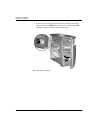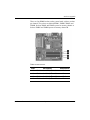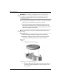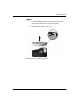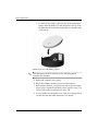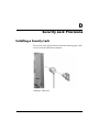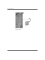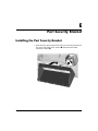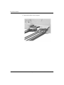
1
Hardware Reference Guide
HP Compaq Business Desktops
d330 Microtower Model
Document Part Number: 323353-002
September 2003
This guide provides basic information for upgrading this computer
model.
© Copyright 2003 Hewlett-Packard Development Company, L.P.
The information contained herein is subject to change without notice.
Microsoft, MS-DOS, Windows, and Windows NT are trademarks of Microsoft
Corporation in the U.S. and other countries.
Intel, Pentium, Intel Inside, and Celeron are trademarks of Intel Corporation in
the U.S. and other countries.
Adobe, Acrobat, and Acrobat Reader are trademarks or registered trademarks of
Adobe Systems Incorporated.
The only warranties for HP products and services are set forth in the express
warranty statements accompanying such products and services. Nothing herein
should be construed as constituting an additional warranty. HP shall not be liable
for technical or editorial errors or omissions contained herein.
This document contains proprietary information that is protected by copyright.
No part of this document may be photocopied, reproduced, or translated to
another language without the prior written consent of Hewlett-Packard
Company.
Å
WARNING: Text set off in this manner indicates that failure to follow
directions could result in bodily harm or loss of life.
Ä
CAUTION: Text set off in this manner indicates that failure to follow
directions could result in damage to equipment or loss of information.
Hardware Reference Guide
HP Compaq Business Desktops
d330 Microtower Model
Second Edition (September 2003)
First Edition (May 2003)
Document Part Number: 323353-002
Contents
1 Product Features
Standard Configuration Features. . . . . . . . . . . . . . . . . . . . . . . . . . . . . . . . . . . . . . . . . .
Front Panel Components . . . . . . . . . . . . . . . . . . . . . . . . . . . . . . . . . . . . . . . . . . . . . . . .
Rear Panel Components . . . . . . . . . . . . . . . . . . . . . . . . . . . . . . . . . . . . . . . . . . . . . . . .
Easy Access Keyboard . . . . . . . . . . . . . . . . . . . . . . . . . . . . . . . . . . . . . . . . . . . . . . . . .
Customizing the Easy Access Buttons . . . . . . . . . . . . . . . . . . . . . . . . . . . . . . . . . .
Windows Logo Key . . . . . . . . . . . . . . . . . . . . . . . . . . . . . . . . . . . . . . . . . . . . . . . .
Special Mouse Functions. . . . . . . . . . . . . . . . . . . . . . . . . . . . . . . . . . . . . . . . . . . . . . . .
Serial Number Location . . . . . . . . . . . . . . . . . . . . . . . . . . . . . . . . . . . . . . . . . . . . . . . .
1–1
1–2
1–3
1–4
1–5
1–5
1–6
1–6
2 Hardware Upgrades
Serviceability Features . . . . . . . . . . . . . . . . . . . . . . . . . . . . . . . . . . . . . . . . . . . . . . . . . 2–1
Warnings and Cautions . . . . . . . . . . . . . . . . . . . . . . . . . . . . . . . . . . . . . . . . . . . . . . . . . 2–1
Removing the Computer Access Panel and Front Bezel. . . . . . . . . . . . . . . . . . . . . . . . 2–2
Installing Additional Memory . . . . . . . . . . . . . . . . . . . . . . . . . . . . . . . . . . . . . . . . . . . . 2–5
DIMMs . . . . . . . . . . . . . . . . . . . . . . . . . . . . . . . . . . . . . . . . . . . . . . . . . . . . . . . . . . 2–5
DDR-SDRAM DIMMs. . . . . . . . . . . . . . . . . . . . . . . . . . . . . . . . . . . . . . . . . . . . . . 2–5
DIMM Sockets . . . . . . . . . . . . . . . . . . . . . . . . . . . . . . . . . . . . . . . . . . . . . . . . . . . . 2–6
Installing DDR-SDRAM DIMMs . . . . . . . . . . . . . . . . . . . . . . . . . . . . . . . . . . . . . 2–8
Replacing or Upgrading a Drive . . . . . . . . . . . . . . . . . . . . . . . . . . . . . . . . . . . . . . . . . 2–10
Locating Drive Positions . . . . . . . . . . . . . . . . . . . . . . . . . . . . . . . . . . . . . . . . . . . 2–10
Removing a Drive. . . . . . . . . . . . . . . . . . . . . . . . . . . . . . . . . . . . . . . . . . . . . . . . . 2–11
Replacing a Drive . . . . . . . . . . . . . . . . . . . . . . . . . . . . . . . . . . . . . . . . . . . . . . . . . 2–14
Removing or Installing an Expansion Card . . . . . . . . . . . . . . . . . . . . . . . . . . . . . . . . 2–19
Reassembling the Computer . . . . . . . . . . . . . . . . . . . . . . . . . . . . . . . . . . . . . . . . . . . . 2–25
Hardware Reference Guide
www.hp.com
iii
Contents
A Specifications
B PATA Hard Drive Installation Guidelines
Using the Cable-Select Feature with Parallel ATA (PATA) Devices. . . . . . . . . . . . . . B–1
Guidelines for Installing PATA Drives . . . . . . . . . . . . . . . . . . . . . . . . . . . . . . . . . B–2
C Battery Replacement
D Security Lock Provisions
Installing a Security Lock . . . . . . . . . . . . . . . . . . . . . . . . . . . . . . . . . . . . . . . . . . . . . . . D–1
E Port Security Bracket
Installing the Port Security Bracket. . . . . . . . . . . . . . . . . . . . . . . . . . . . . . . . . . . . . . . . E–1
Removing the Port Security Bracket . . . . . . . . . . . . . . . . . . . . . . . . . . . . . . . . . . . . . . . E–5
F Electrostatic Discharge
Preventing Electrostatic Damage . . . . . . . . . . . . . . . . . . . . . . . . . . . . . . . . . . . . . . . . . F–1
Grounding Methods. . . . . . . . . . . . . . . . . . . . . . . . . . . . . . . . . . . . . . . . . . . . . . . . . . . . F–1
G Routine Computer Care and Shipping Preparation
Routine Computer Care. . . . . . . . . . . . . . . . . . . . . . . . . . . . . . . . . . . . . . . . . . . . . . . . .
Optical Drive Precautions . . . . . . . . . . . . . . . . . . . . . . . . . . . . . . . . . . . . . . . . . . . . . . .
Operation . . . . . . . . . . . . . . . . . . . . . . . . . . . . . . . . . . . . . . . . . . . . . . . . . . . . . . . .
Cleaning . . . . . . . . . . . . . . . . . . . . . . . . . . . . . . . . . . . . . . . . . . . . . . . . . . . . . . . . .
Safety . . . . . . . . . . . . . . . . . . . . . . . . . . . . . . . . . . . . . . . . . . . . . . . . . . . . . . . . . . .
Shipping Preparation . . . . . . . . . . . . . . . . . . . . . . . . . . . . . . . . . . . . . . . . . . . . . . . . . . .
G–1
G–2
G–2
G–2
G–2
G–3
Index
iv
www.hp.com
Hardware Reference Guide
1
Product Features
Standard Configuration Features
The HP Compaq Microtower features may vary depending on the
model. For a complete listing of the hardware and software installed
in the computer, run the Diagnostics for Windows utility. Instructions
for using this utility are provided in the Troubleshooting Guide on the
Documentation Library CD.
Microtower Configuration
Hardware Reference Guide
www.hp.com
1–1
Product Features
Front Panel Components
Drive configuration may vary by model.
Front Panel Components
1
Optical Drives (CD-ROM, CD-R/RW,
DVD-ROM, DVD-R/RW, or CD-RW/DVD
Combo Drive)
7
Optical Drive Eject Buttons
2
Optical Drive Activity Lights
8
Power Button
3
Diskette Drive (optional)
9
Power On Light
4
Diskette Drive Activity Light (optional)
-
Hard Drive Activity Light
5
Diskette Eject Button (optional)
q
Headphone Jack
6
USB (Universal Serial Bus) Ports
w
Microphone Connector
1–2
www.hp.com
Hardware Reference Guide
Product Features
Rear Panel Components
Rear Panel Components
1
Power Cord Connector
7
n RJ-45 Network Connector
2
Voltage Select Switch
8
l Parallel Connector
PS/2 Mouse Connector
9
c Monitor Connector
3
b
4
a PS/2 Keyboard Connector
-
h Headphone/Line-Out Connector
5
o Universal Serial Bus (USB)
q
j Line-In Audio Connector
6
m
w
g
Serial Connector
Microphone Connector
✎ Arrangement and number of connectors may vary by model.
The monitor connector on the system board is inactive when an AGP expansion card is installed in
the computer, or when both an AGP and PCI graphics card are installed.
If only a PCI graphics card is installed, the connectors on the card and the system board may be
used at the same time. Some settings may need to be changed in F10 setup to use both connectors.
For more information about Boot Order, refer to the Computer Setup (F10) Utility Guide on the
Documentation Library CD.
If you have installed an AGP and PCI graphics card, the connectors on both cards are active and
can be used at the same time.
Hardware Reference Guide
www.hp.com
1–3
Product Features
Easy Access Keyboard
Easy Access Keyboard Components
1 Function Keys
Perform special functions depending on the software application
being used.
2 Easy Access Buttons
Provide quick access to specific Internet destinations.
3 Editing Keys
Includes the following: Insert, Home, Page Up, Delete, End, and
Page Down.
4 Status Lights
Indicate the status of the computer and keyboard settings
(Num Lock, Caps Lock, and Scroll Lock).
5 Numeric Keys
Work like a calculator keypad.
6 Arrow Keys
Used to navigate through a document or Web site. These keys
allow you to move left, right, up, and down, using the keyboard
instead of the mouse.
7 Application Key*
Used (like the right mouse button) to open pop-up menus in a
Microsoft Office application. May perform other functions in other
software applications.
8 Windows Logo Key*
Used to open the Start menu in Microsoft Windows. Used in
combination with other keys to perform other functions.
9 Ctrl Key
Used in combination with another key; its effect depends on the
application software you are using.
*Keys available in select geographic regions.
1–4
www.hp.com
Hardware Reference Guide
Product Features
Customizing the Easy Access Buttons
All Easy Access buttons can be reprogrammed to open any software
application or data file on the hard drive, or any Internet address.
To reprogram the Easy Access buttons, complete the following steps:
1. Double-click the keyboard icon in the notification area (lower
right corner) of the Windows taskbar. The Keyboard Properties
dialog box is displayed.
2. Click the Help button on the Keyboard Properties dialog box for
instructions.
Windows Logo Key
Use the Windows Logo key in combination with other keys to
perform certain functions available in the Windows operating system.
Refer to the “Easy Access Keyboard” section to identify the Windows
Logo key.
Windows Logo Key Functions
Windows Logo Key
Displays or hides the Start menu.
Windows Logo Key + d
Displays the Desktop.
Windows Logo Key + m
Minimizes all open applications.
Shift + Windows Logo Key + m
Undoes Minimize All.
Windows Logo Key + e
Launches My Computer.
Windows Logo Key + f
Launches Find Document.
Windows Logo Key + Ctrl + f
Launches Find Computer.
Windows Logo Key + F1
Launches Windows Help.
Windows Logo Key + l
Locks the computer if you are connected to a
network domain, or allows you to switch users if you
are not connected to a network domain.
Windows Logo Key + r
Launches the Run dialog box.
Windows Logo Key + u
Launches the Utility Manager.
Windows Logo Key + Tab
Activates the next Taskbar button.
Hardware Reference Guide
www.hp.com
1–5
Product Features
Special Mouse Functions
Most software applications support the use of a mouse. The functions
assigned to each mouse button depend on the software applications
you are using.
Serial Number Location
Each computer has a unique serial number that is located on the
top cover of the computer. Keep this number available for use when
contacting HP customer service for assistance.
Serial Number Location
1–6
www.hp.com
Hardware Reference Guide
2
Hardware Upgrades
Serviceability Features
The Microtower computer includes features that make it easy to
upgrade and service. No tools are needed for most of the installation
procedures described in this chapter.
Warnings and Cautions
Before performing upgrades be sure to carefully read all of the
applicable instructions, cautions, and warnings in this guide.
Å
WARNING: To reduce the risk of personal injury from electrical shock
and/or hot surfaces, be sure to disconnect the power cord from the wall
outlet and allow the internal system components to cool before touching.
Å
WARNING: To reduce the risk of electrical shock, fire, or damage to the
equipment, do not plug telecommunications/telephone connectors into the
network interface controller (NIC) receptacles.
Ä
CAUTION: Static electricity can damage the electrical components of the
computer or optional equipment. Before beginning these procedures,
ensure that you are discharged of static electricity by briefly touching a
grounded metal object. See Appendix F, “Electrostatic Discharge” for
more information.
Ä
CAUTION: Before removing the computer cover, ensure that the
computer is turned off and that the power cord is disconnected from the
electrical outlet.
Hardware Reference Guide
www.hp.com
2–1
Hardware Upgrades
Removing the Computer Access Panel and
Front Bezel
To remove the computer access panel:
1. If you have locked the Smart Cover Lock, use Computer Setup to
unlock the lock. Refer to the Desktop Management Guide on the
Documentation Library CD for more information about the Smart
Cover Lock.
you enable the Smart Cover Lock and cannot disable the lock
✎ Ifthrough
Computer Setup, you will need a Smart Cover FailSafe Key
to remove the screws that retain the lock and open the computer
cover. Contact an authorized HP reseller or service provider and order
PN 166527-001 for the wrench-style key or PN 166527-002 for the
screwdriver bit key.
2. Turn off the computer properly through the operating system and
turn off any external devices.
3. Disconnect the power cord from the power outlet 1 and the
computer 2, and disconnect any external devices.
Disconnecting the Power Cable
2–2
www.hp.com
Hardware Reference Guide
Hardware Upgrades
Ä
CAUTION: Before removing the computer access panel, ensure that the
computer is turned off and that the power cord is disconnected from the
electrical outlet.
4. Loosen the captive thumbscrew 1 that secures the access panel to
the computer chassis.
5. Slide the access panel 2 back about 1 inch (2.5 cm), then lift it
off the unit.
may want to lay the computer on its side to install internal parts.
✎ You
Be sure the side with the access panel and pull grip is facing up.
Removing the Computer Access Panel
Hardware Reference Guide
www.hp.com
2–3
Hardware Upgrades
6. To remove the front bezel, press down on all three tabs on the
left side of the bezel 1 then rotate the bezel off the chassis 2,
beginning with the left side then the right side.
Removing the Front Bezel
2–4
www.hp.com
Hardware Reference Guide
Hardware Upgrades
Installing Additional Memory
The computer comes with double data rate synchronous dynamic
random access memory (DDR-SDRAM) dual inline memory
modules (DIMMs).
DIMMs
The memory sockets on the system board can be populated with up to
four industry-standard DIMMs. These memory sockets are populated
with at least one preinstalled DIMM. To achieve the maximum
memory support, you can populate the system board with up to 4GB
of memory configured in a high-performing dual channel mode.
DDR-SDRAM DIMMs
For proper system operation, if the computer supports DDR-SDRAM
DIMMs, the DIMMs must be:
■
industry-standard 184-pin
■
unbuffered PC2100 266 MHz-, PC2700 333 MHz-, or PC3200
400 MHz-compliant
■
2.5 volt DDR-SDRAM DIMMs.
The DDR-SDRAM DIMMs must also:
■
support CAS latency 2 or 2.5 (CL = 2 or CL = 2.5)
■
contain the mandatory JEDEC SPD information
In addition, the computer supports:
■
128Mbit, 256Mbit, and 512Mbit non-ECC memory technologies
■
single-sided and double-sided DIMMS
■
DIMMs constructed with x8 and x16 DDR devices; DIMMs
constructed with x4 SDRAM are not supported
The following processor bus frequencies are required for the system
to run at the supported memory frequencies.
Hardware Reference Guide
www.hp.com
2–5
Hardware Upgrades
Memory Frequency
Required Processor Bus Frequency
266 MHz
400 MHz, 533 MHz, or 800 MHz
333 MHz
533 MHz or 800 MHz
400 MHz
800 MHz
If a memory frequency is paired with an unsupported processor bus
frequency, the system will run at the highest supported memory
speed. For example, if a 333 MHz DIMM is paired with a 400 MHz
processor bus, the system will run at 266 MHz, the highest supported
memory speed.
✎ The system will not start if you install unsupported DIMMs.
DIMM Sockets
The system will automatically operate in single channel mode or a
higher-performing dual channel mode, depending on how the DIMMs
are installed.
2–6
■
In single channel mode, the maximum operational speed is
determined by the slowest DIMM in the system. For example, if
the system is populated with a DIMM that is 266 MHz and a
second DIMM that is 333 MHz, the system will run at the slower
of the two speeds.
■
In dual channel mode, all DIMMs must be identically matched.
DIMMs in the XMM1 and XMM3 black sockets must be
identical; DIMMs in the XMM2 and XMM4 blue sockets must
also be identical. Therefore, if you have one preinstalled DIMM
in socket XMM1 and are adding a second DIMM, it is
recommended that you install an identical DIMM into the XMM3
socket. If you are populating all four DIMM sockets, use identical
DIMMs in each socket. Otherwise, the system will not operate in
dual channel mode.
www.hp.com
Hardware Reference Guide
Hardware Upgrades
There are four DIMM sockets on the system board, with two sockets
per channel. The sockets are labeled XMM1, XMM2, XMM3, and
XMM4. Sockets XMM1 and XMM2 operate in memory channel A.
Sockets XMM3 and XMM4 operate in memory channel B.
DIMM Socket Locations
Hardware Reference Guide
Item
Description
Socket Color
1
DIMM socket XMM1, Channel A
Black
2
DIMM socket XMM2, Channel A
Blue
3
DIMM socket XMM3, Channel B
Black
4
DIMM socket XMM4, Channel B
Blue
www.hp.com
2–7
Hardware Upgrades
Installing DDR-SDRAM DIMMs
Ä
CAUTION: The memory module sockets have gold metal contacts. When
upgrading the memory, it is important to use memory modules with gold
metal contacts to prevent corrosion and/or oxidation resulting from having
incompatible metals in contact with each other.
Ä
CAUTION: Static electricity can damage the electronic components of
the computer or optional cards. Before beginning these procedures,
ensure that you are discharged of static electricity by briefly touching a
grounded metal object. For more informations, refer to Appendix F,
“Electrostatic Discharge”.
Ä
CAUTION: When handling a memory module, be careful not to touch
any of the contacts. Doing so may damage the module.
1. If you have locked the Smart Cover Lock, use Computer Setup to
unlock the lock.
2. Turn off the computer properly through the operating system and
turn off any external devices. Disconnect the power cord from the
power outlet.
3. Remove the access panel and locate the memory module sockets.
Å
WARNING: To reduce risk of personal injury from hot surfaces, allow
the internal system components to cool before touching.
4. Open both latches of the memory module socket 1, and insert the
memory module into the socket 2.
you have one preinstalled DIMM in socket XMM1 and are adding a
✎ Ifsecond
DIMM, it is recommended that you install an identical DIMM
into the XMM3 socket. If you are populating all four DIMM sockets,
use identical DIMMs in each socket. Otherwise, the system will not
operate in dual channel mode.
2–8
www.hp.com
Hardware Reference Guide
Hardware Upgrades
Installing a DIMM
module can be installed in only one way. Match the notch
✎ Aonmemory
the module with the tab on the memory socket.
5. Push the module down into the socket, ensuring that the module
is fully inserted and properly seated. Make sure the latches are in
the closed position 3.
6. Repeat steps 4 and 5 to install any additional modules.
7. Replace the access panel.
8. If you normally lock the Smart Cover Lock, use Computer Setup
to relock the lock and enable the Smart Cover Sensor.
The computer should automatically recognize the additional memory
the next time you turn on the computer.
Hardware Reference Guide
www.hp.com
2–9
Hardware Upgrades
Replacing or Upgrading a Drive
The computer supports up to six drives that may be installed in
various configurations.
This section describes the procedure for replacing or upgrading the
storage drives. A Torx screwdriver is needed to replace the guide
screws on a drive.
Ä
CAUTION: Make sure you back up your personal files on the hard drive
to an external storage device, such as a CD, before removing the hard
drive. Failure to do so will result in data loss. After replacing the primary
hard drive, you will need to run the Restore Plus! CD to load the HP
factory-installed files.
Locating Drive Positions
Drive Positions
2–10
1
Two 5.25-inch, half-height bays for optional drives
2
Two standard 3.5-inch, one-third height bays (1.44-MB
diskette drive shown)
3
Two internal 3.5-inch, one-third height bays for hard drives
www.hp.com
Hardware Reference Guide
Hardware Upgrades
Removing a Drive
1. If you have locked the Smart Cover Lock, use Computer Setup to
unlock the lock.
2. Turn off the computer properly through the operating system and
turn off any external devices. Disconnect the power cord from the
power outlet and disconnect any external devices.
3. Remove the access panel and front bezel.
4. Disconnect the power and data cables from the back of the drive,
as indicated in the following illustrations.
Disconnecting the Optical Drive Cables
Hardware Reference Guide
www.hp.com
2–11
Hardware Upgrades
Disconnecting the Diskette Drive Cables
Disconnecting the Hard Drive Cables (connectors may vary)
2–12
www.hp.com
Hardware Reference Guide
Hardware Upgrades
5. A latch drive bracket with release tabs secures the drives in the
drive bay. Lift the release tab on the latch drive bracket 1 for
the drive you want to remove, then slide the drive from its drive
bay 2.
Removing the Drives
6. Remove the four guide screws (two on each side) from the old
drive. You will need these screws to install a new drive.
Hardware Reference Guide
www.hp.com
2–13
Hardware Upgrades
Replacing a Drive
Ä■
CAUTION: To prevent loss of work and damage to the computer or drive:
If you are inserting or removing a hard drive, shut down the operating
system properly, then turn off the computer. Do not remove a hard
drive while the computer is on or in standby mode.
■
Before handling a drive, ensure that you are discharged of static
electricity. While handling a drive, avoid touching the connector. For
more information about preventing electrostatic damage, refer to
Appendix F, “Electrostatic Discharge.”
■
■
■
Handle a drive carefully; do not drop it.
Do not use excessive force when inserting a drive.
Avoid exposing a hard drive to liquids, temperature extremes, or
products that have magnetic fields such as monitors or speakers.
le:
parallel advanced technology attachment (PATA) and serial
✎ Both
advanced technology attachment (SATA) hard drives can be installed
on this computer.
If you are installing a SATA drive in your computer for the first time,
refer to the white paper “Implementation of Serial ATA on HP
Business Desktops” for more information. The white paper is located
at www.hp.com/support.
sure to back up the data on the old hard drive before removing
✎ Make
it so that you can install the data onto the new hard drive.
2–14
www.hp.com
Hardware Reference Guide
Hardware Upgrades
1. Install the four guide screws (two on each side) that were
removed from the old drive into the new drive. The screws help
guide the drive into its proper position in the bay. Extra guide
screws are provided on the front of the chassis under the front
bezel.
are a total of eight extra guide screws on the front of the chassis
✎ There
under the bezel. Four have 6-32 standard threads and four have M3
metric threads. Standard screws are used for hard drives and have a
silver finish. Metric screws are used for all other drives and have a
black finish. Make sure to install the appropriate guide screws into the
drive.
2. Slide the drive into the drive bay, making sure to align the guide
screws with the guide slots, until the drive snaps into place.
Sliding the Drives into the Drive Cage
Hardware Reference Guide
www.hp.com
2–15
Hardware Upgrades
3. Reconnect the power and data cables to the drive as indicated in
the following illustrations.
Reconnecting the Optical Drive Cables
Reconnecting the Diskette Drive Cables
2–16
www.hp.com
Hardware Reference Guide
Hardware Upgrades
Reconnecting the Hard Drive Cables (connectors may vary)
Hardware Reference Guide
www.hp.com
2–17
Hardware Upgrades
4. If installing a new hard drive, connect the power and data cables
to the system board.
has only one SATA hard drive, you must connect the
✎ Ifhardyourdrivesystem
to the connector labeled SATA 0 first to avoid any hard
drive performance problems.
Hard Drive Connector Locations
1
SATA hard drive connector
2
PATA hard drive connector
5. Complete the procedure described in the “Reassembling the
Computer” section of this chapter.
2–18
www.hp.com
Hardware Reference Guide
Hardware Upgrades
6. Turn on the computer.
If you have installed a PATA hard drive that is not automatically
recognized by the computer, see Appendix B, “PATA Hard Drive
Installation Guidelines.”
If you have installed a SATA hard drive that is not automatically
recognized by the computer, refer to the white paper “Implementation
of Serial ATA on HP Business Desktops” for operating system
instructions. The white paper is located at www.hp.com/support.
you replaced the primary hard drive, insert the Restore Plus! CD to
✎ Ifrestore
the operating system, software drivers, and/or any software
applications that were preinstalled on the computer from HP. Follow
the instructions in the guide included with the restore CD. When the
restore process has completed, reinstall any personal files that you
backed up before replacing the hard drive.
Removing or Installing an Expansion Card
No tools are needed to remove, replace, or add an expansion card.
1. If you have locked the Smart Cover Lock, use Computer Setup to
unlock the lock.
2. Turn off the computer properly through the operating system and
turn off any external devices. Disconnect the power cord from the
power outlet and disconnect any external devices.
3. Remove the access panel and lay the computer on its side with the
opening to internal parts where the access panel was located
facing up.
Hardware Reference Guide
www.hp.com
2–19
Hardware Upgrades
4. On the rear of the computer, a sliding slot cover lock secures the
expansion card brackets and expansion slot covers in place. Slide
the slot cover lock away from the brackets so that they are no
longer secured by the lock.
Releasing the Slot Cover Lock
5. Inside the computer, locate the correct vacant expansion slot on
the system board and remove the corresponding slot cover.
2–20
www.hp.com
Hardware Reference Guide
Hardware Upgrades
6. If removing an expansion card from a standard expansion socket,
hold the card at each end, and carefully rock it back and forth
until the connectors pull free from the socket. Pull the expansion
card straight up from the socket 1 then away from the inside of
the chassis 2 to release it from the chassis frame. Be sure not to
scrape the card against the other components.
Removing an Expansion Card from a Standard Expansion Socket
Hardware Reference Guide
www.hp.com
2–21
Hardware Upgrades
7. If removing an AGP card from an AGP expansion socket with a
retention mechanism, pull the retention arm away from the socket
then carefully rock the card back and forth until the connectors
pull free from the socket. Pull the expansion card straight up from
the socket then away from the inside of the chassis to release it
from the chassis frame. Be sure not to scrape the card against the
other components.
Removing an AGP Card from a Socket with a Retention Mechanism
8. If not replacing the old expansion card with a new expansion
card, install an expansion slot cover to close the open slot. Insert
the metal slot cover in the opened slot and slide the slot cover
lock down to secure the slot cover in place.
Ä
2–22
CAUTION: After removing an expansion card, you must replace it with a
new card or cover the open slot (for example, with a metal slot cover or a
piece of duct tape) for proper cooling of internal components during
operation.
www.hp.com
Hardware Reference Guide
Hardware Upgrades
9. If replacing or adding a new expansion card, hold the card just
above the expansion slot on the system board then move the card
toward the rear of the chassis so that the bracket on the card is
aligned with the open slot on the rear of the chassis 1. Gently
press the card straight down into the expansion slot on the system
board 2.
Replacing or Adding an Expansion Card
installing an expansion card, press firmly on the card so that
✎ When
the whole connector seats properly in the expansion card slot.
10. If you are replacing an expansion card, store the old card in the
anti-static packaging that contained the new card.
Hardware Reference Guide
www.hp.com
2–23
Hardware Upgrades
11. While holding the expansion card bracket against the chassis,
slide the slot cover lock down toward the expansion card brackets
and slot covers to secure them in place.
Securing the Expansion Cards and Slot Covers
12. Complete the procedure described in the “Reassembling the
Computer” section of this chapter.
2–24
www.hp.com
Hardware Reference Guide
Hardware Upgrades
Reassembling the Computer
1. Position the chassis in the upright position. Insert the three hooks
on the right side of the bezel 1 into the rectangular holes on the
chassis then rotate the bezel into place so that the three tabs on the
left side of the bezel snap into the slots on the chassis 2.
Replacing the Front Bezel
Hardware Reference Guide
www.hp.com
2–25
Hardware Upgrades
2. Place the side access panel in the proper position on the
chassis and slide it into place 1. Ensure that the hole for the
thumbscrew is aligned with the hole in the chassis and tighten
the thumbscrew 2.
Replacing the Side Access Panel
2–26
www.hp.com
Hardware Reference Guide
Hardware Upgrades
3. Reconnect the power cable to the computer 1 and plug the cable
into an electrical outlet 2.
Reconnecting the Power Cable
4. Reconnect all peripheral devices to the computer.
Å
WARNING: To reduce the risk of electrical shock, fire, or damage to the
equipment, do not plug telecommunications or telephone connectors into
the network interface controller (NIC) ports.
5. Turn on the computer by pressing the power button.
6. If you normally lock the Smart Cover Lock, use Computer Setup
to relock the lock and enable the Smart Cover Sensor. Refer to the
Desktop Management Guide on the Documentation Library CD
for more information about the Smart Cover Lock and Smart
Cover Sensor.
Hardware Reference Guide
www.hp.com
2–27
Hardware Upgrades
2–28
www.hp.com
Hardware Reference Guide
A
Specifications
HP Compaq d330 Microtower
Microtower Dimensions
Height
Width
Depth (depth will increase if the computer is
equipped with a port security bracket)
Approximate Weight
14.5 in
6.88 in
16.5 in
36.8 cm
17.5 cm
42.0 cm
23.8 lb
10.82 kg
50° to 95°F
-22° to 140°F
10° to 35°C
-30° to 60°C
10-90%
5-95%
10-90%
5-95%
10,000 ft
30,000 ft
3048 m
9144 m
1260 BTU/hr
256 BTU/hr
317 kg-cal/hr
65 kg-cal/hr
Temperature Range
Operating
Nonoperating
Relative Humidity (noncondensing)
Operating
Nonoperating
Maximum Altitude (unpressurized)
Operating
Nonoperating
Heat Dissipation
Maximum
Typical
Hardware Reference Guide
www.hp.com
A–1
Specifications
HP Compaq d330 Microtower (Continued)
Input Voltage Switch Setting
115 V
230 V
90-132 VAC
100-127 VAC
50-60 Hz
180-264 VAC
200-240 VAC
50-60 Hz
240 W
240 W
6 A @100 VAC
3 A @ 200 VAC
Power Supply
Operating Voltage Range
Rated Voltage Range
Rated Line Frequency
Power Output
Rated Input Current (maximum)
A–2
www.hp.com
Hardware Reference Guide
B
PATA Hard Drive Installation Guidelines
more information about Serial ATA (SATA) devices, refer to the
✎ For
white paper “Implementation of Serial ATA on HP Business
Desktops”. The white paper is located at www.hp.com/support.
Using the Cable-Select Feature with Parallel ATA
(PATA) Devices
Optional drives are available from HP in kits that include a special
drive cable. The configuration of the drive employs a cable-select
feature that identifies the drive as device 0 (primary drive) or device 1
(secondary drive).
Device 1 is the drive connected to the cable’s middle connector.
Device 0 is the drive connected to the cable’s end connector (applies
only to 80-conductor ATA cables). See “Guidelines for Installing
PATA Drives” in this appendix for an example of an PATA cable.
HP hard drives ship with jumpers preset to cable-select mode;
therefore, no jumper setting changes on the existing or optional drives
are required. If you purchase a third-party hard drive, refer to the
documentation included with the kit to ensure proper installation and
configuration of cables.
a second device on the primary controller, you must use
✎ Ifaninstalling
80-conductor PATA cable for optimal performance. This cable is
standard on select models.
Hardware Reference Guide
www.hp.com
B–1
PATA Hard Drive Installation Guidelines
Guidelines for Installing PATA Drives
When installing additional drives, follow these guidelines:
■
If using multiple devices, HP recommends that the devices be
split between the primary and secondary channels for optimum
performance. Use an additional cable to connect the additional
device to the system board.
■
80-conductor PATA cable:
❏
18 inches maximum total length, 80-conductor cable with
maximum spacing of 6 inches between Device 0 and
Device 1.
80-Conductor PATA Cable
B–2
1
Device 0 (primary drive) connector
2
Device 1 (secondary drive) connector
3
System board connector
■
For optimal performance, connect hard drives to the primary
controller. Connect expansion devices, such as ATA optical drives
and tape drives, to the secondary controller.
■
Install either a third-height or a half-height drive into a
half-height bay.
■
Install guide screws to ensure that the drive lines up correctly in
the drive cage. Hard drives use 6-32 standard guide screws. Four
extra guide screws are installed on the hard drive bracket under
the access panel. HP-supplied standard screws are silver.
■
If only one device is connected to a cable, that device must be
attached to the end (Device 0) connector.
www.hp.com
Hardware Reference Guide
PATA Hard Drive Installation Guidelines
you have only one device, make sure to connect it to the Device 0
✎ Ifconnector.
If you connect it to the Device 1 connector, the system will
not recognize the device and you may receive a “no fixed disk found”
error message.
Hardware Reference Guide
www.hp.com
B–3
PATA Hard Drive Installation Guidelines
B–4
www.hp.com
Hardware Reference Guide
C
Battery Replacement
The battery that comes with the computer provides power to the
real-time clock. When replacing the battery, use a battery equivalent
to the battery originally installed in the computer. The computer
comes with a 3-volt lithium coin cell battery.
lifetime of the lithium battery can be extended by plugging the
✎ The
computer into a live AC wall socket. The lithium battery is only used
when the computer is NOT connected to AC power.
Å
WARNING: The computer contains an internal lithium manganese dioxide
battery. There is a risk of fire and burns if the battery is not handled properly. To
reduce the risk of personal injury:
■
■
■
Do not attempt to recharge the battery.
■
Replace the battery only with the HP spare designated for this product.
Do not expose to temperatures higher than 60°C (140ºF).
Do not disassemble, crush, puncture, short external contacts, or
dispose of in fire or water.
Ä
CAUTION: Before replacing the battery, it is important to back up the
computer CMOS settings. When the battery is removed or replaced, the
CMOS settings will be cleared. Refer to the Troubleshooting Guide on the
Documentation Library CD for information on backing up the CMOS
settings.
N
Batteries, battery packs, and accumulators should not be disposed of
together with the general household waste. In order to forward them to
recycling or proper disposal, please use the public collection system or
return them to HP, their authorized partners, or their agents.
Hardware Reference Guide
www.hp.com
C–1
Battery Replacement
Ä
CAUTION: Static electricity can damage the electronic components of
the computer or optional equipment. Before beginning these procedures,
ensure that you are discharged of static electricity by briefly touching a
grounded metal object.
1. If you have locked the Smart Cover Lock, use Computer Setup to
unlock the lock and disable the Smart Cover Sensor.
2. Turn off the computer properly through the operating system,
then turn off any external devices. Disconnect the power cord
from the power outlet and disconnect any external devices. Then
remove the computer access panel.
be necessary to remove an expansion card to gain access to
✎ Itthemay
battery.
3. Locate the battery and battery holder on the system board.
4. Depending on the type of battery holder on the system board,
complete the following instructions to replace the battery.
Type 1
a. Lift the battery out of its holder.
Removing a Coin Cell Battery (Type 1)
b. Slide the replacement battery into position, positive side up.
The battery holder automatically secures the battery in the
proper position.
C–2
www.hp.com
Hardware Reference Guide
Battery Replacement
Type 2
a. To release the battery from its holder, squeeze the metal
clamp that extends above one edge of the battery.
b. When the battery pops up, lift it out.
Removing a Coin Cell Battery (Type 2)
Hardware Reference Guide
www.hp.com
C–3
Battery Replacement
c. To insert the new battery, slide one edge of the replacement
battery under the holder’s lip with the positive side up. Push
the other edge down until the clamp snaps over the other edge
of the battery.
Replacing a Coin Cell Battery (Type 2)
the battery has been replaced, use the following steps to
✎ After
complete this procedure.
5. Replace the computer access panel.
6. Plug in the computer and turn on power to the computer.
7. Reset the date and time, your passwords, and any special system
setups, using Computer Setup. Refer to the Computer Setup (F10)
Utility Guide on the Documentation Library CD.
8. If you normally lock the Smart Cover Lock, use Computer Setup
to relock the lock and enable the Smart Cover Sensor.
C–4
www.hp.com
Hardware Reference Guide
D
Security Lock Provisions
Installing a Security Lock
The security locks displayed below and on the following page can be
used to secure the Microtower computer.
Installing a Cable Lock
Hardware Reference Guide
www.hp.com
D–1
Security Lock Provisions
I
Installing a Padlock
D–2
www.hp.com
Hardware Reference Guide
E
Port Security Bracket
Installing the Port Security Bracket
1. Insert the tabs on the bottom half of the port security bracket into
the slots on the back of the chassis 1 and rotate the bracket
toward the chassis 2.
Hardware Reference Guide
www.hp.com
E-1
Port Security Bracket
2. Connect the cables to the computer.
E-2
www.hp.com
Hardware Reference Guide
Port Security Bracket
3. Position the top of the port security bracket over the cables 1 and
rotate the the bracket into place 2.
Hardware Reference Guide
www.hp.com
E-3
Port Security Bracket
4. The illustration below shows the proper installation.
E-4
www.hp.com
Hardware Reference Guide
Port Security Bracket
Removing the Port Security Bracket
1. Loosen the captive thumbscrew 1 that secures the access panel to
the computer chassis.
2. Slide the access panel 2 back about 1 inch (2.5 cm), then lift it
off the unit.
Hardware Reference Guide
www.hp.com
E-5
Port Security Bracket
3. Push in on the tabs 1 and rotate the top of the bracket away from
the computer 2.
E-6
www.hp.com
Hardware Reference Guide
Port Security Bracket
4. Disconnect the cables from the computer.
Hardware Reference Guide
www.hp.com
E-7
Port Security Bracket
5. Push on the tabs to release the bottom of the bracket from the
chassis 1. Rotate the bracket away from the chassis 2.
E-8
www.hp.com
Hardware Reference Guide
F
Electrostatic Discharge
A discharge of static electricity from a finger or other conductor may
damage system boards or other static-sensitive devices. This type of
damage may reduce the life expectancy of the device.
Preventing Electrostatic Damage
To prevent electrostatic damage, observe the following precautions:
■
Avoid hand contact by transporting and storing products in
static-safe containers.
■
Keep electrostatic-sensitive parts in their containers until they
arrive at static-free workstations.
■
Place parts on a grounded surface before removing them from
their containers.
■
Avoid touching pins, leads, or circuitry.
■
Always be properly grounded when touching a static-sensitive
component or assembly.
Grounding Methods
There are several methods for grounding. Use one or more of the
following methods when handling or installing electrostatic-sensitive
parts:
■
Hardware Reference Guide
Use a wrist strap connected by a ground cord to a grounded
workstation or computer chassis. Wrist straps are flexible straps
with a minimum of 1 megohm +/- 10 percent resistance in the
ground cords. To provide proper ground, wear the strap snug
against the skin.
www.hp.com
F–1
Electrostatic Discharge
■
Use heelstraps, toestraps, or bootstraps at standing workstations.
Wear the straps on both feet when standing on conductive floors
or dissipating floor mats.
■
Use conductive field service tools.
■
Use a portable field service kit with a folding static-dissipating
work mat.
If you do not have any of the suggested equipment for proper
grounding, contact an HP authorized dealer, reseller, or service
provider.
more information on static electricity, contact an HP authorized
✎ For
dealer, reseller, or service provider.
F–2
www.hp.com
Hardware Reference Guide
G
Routine Computer Care and
Shipping Preparation
Routine Computer Care
Follow these suggestions to take care of the computer and monitor:
Hardware Reference Guide
■
Operate the computer on a sturdy, level surface. Leave a 3-inch
(7.6-cm) clearance at the back of the system unit and above the
monitor to permit the required airflow.
■
Never operate the computer with the cover or side panel removed.
■
Never restrict the airflow into the computer by blocking the front
vents or air intake. Do not place the keyboard, with the keyboard
feet down, directly against the front of the desktop unit as this
also restricts airflow.
■
Keep the computer away from excessive moisture, direct sunlight,
and extremes of heat and cold. For information about the
recommended temperature and humidity ranges for the computer,
refer to Appendix A, “Specifications” in this guide.
■
Keep liquids away from the computer and keyboard.
■
Never cover the ventilation slots on the monitor with any type of
material.
■
Turn off the computer before you do either of the following:
❏
Wipe the exterior of the computer with a soft, damp cloth as
needed. Using cleaning products may discolor or damage the
finish.
❏
Occasionally clean the air vents on the front and back of the
computer. Lint and other foreign matter can block the vents
and limit the airflow.
www.hp.com
G–1
Routine Computer Care and Shipping Preparation
Optical Drive Precautions
Be sure to observe the following guidelines while operating or
cleaning the optical drive.
Operation
■
Do not move the drive during operation. This may cause it to
malfunction during reading.
■
Avoid exposing the drive to sudden changes in temperature, as
condensation may form inside the unit. If the temperature
suddenly changes while the drive is on, wait at least one hour
before you turn off the power. If you operate the unit
immediately, it may malfunction while reading.
■
Avoid placing the drive in a location that is subject to high
humidity, extreme temperatures, mechanical vibration, or direct
sunlight.
■
Clean the panel and controls with a soft, dry cloth or a soft cloth
lightly moistened with a mild detergent solution. Never spray
cleaning fluids directly on the unit.
■
Avoid using any type of solvent, such as alcohol or benzene,
which may damage the finish.
Cleaning
Safety
If any object or liquid falls into the drive, immediately unplug the
computer and have it checked by an authorized HP service provider.
G–2
www.hp.com
Hardware Reference Guide
Routine Computer Care and Shipping Preparation
Shipping Preparation
Follow these suggestions when preparing to ship the computer:
1. Back up the hard drive files on PD discs, tape cartridges, CDs,
or diskettes. Be sure that the backup media is not exposed to
electrical or magnetic impulses while stored or in transit.
hard drive locks automatically when the system power is
✎ The
turned off.
2. Remove and store any program diskettes from the diskette drives.
3. Insert a blank diskette into the diskette drive to protect the drive
while in transit. Do not use a diskette on which you have stored or
plan to store data.
4. Turn off the computer and external devices.
5. Disconnect the power cord from the electrical outlet, then from
the computer.
6. Disconnect the system components and external devices from
their power sources, then from the computer.
that all boards are seated properly and secured in the board
✎ Ensure
slots before shipping the computer.
7. Pack the system components and external devices in their original
packing boxes or similar packaging with sufficient packing
material to protect them.
environmental nonoperating ranges, see Appendix A,
✎ For
“Specifications” in this guide.
Hardware Reference Guide
www.hp.com
G–3
Routine Computer Care and Shipping Preparation
G–4
www.hp.com
Hardware Reference Guide
Index
A
access panel
removing 2–3
replacing 2–26
B
backup files 2–10, 2–19
battery replacement C–1
C
CD-R/RW drive
installing 2–10
locating 2–10
CD-ROM drive
installing 2–10
locating 2–10
components
front panel 1–2
keyboard 1–4
rear panel 1–3
computer
routine care G–1
security lock D–1
shipping preparation G–3
specifications A–1
D
DDR-SDRAM 2–5
DIMMs 2–5
diskette drive
activity light 1–2
eject button 1–2
Hardware Reference Guide
installing 2–10
locating 2–10
drive positions 2–10
DVD-R/RW drive
installing 2–10
locating 2–10
DVD-ROM drive
installing 2–10
locating 2–10
E
electrostatic discharge F–1
expansion card installation 2–19
expansion slots 2–20
F
front bezel
removing 2–4
replacing 2–25
front panel components 1–2
H
hard drive
activity light 1–2
connector locations 2–18
installing PATA 2–10, 2–14, B–1
installing SATA 2–10, 2–14
locating 2–10
PATA cable B–2
restoring 2–19
headphone jack 1–2
www.hp.com
Index–1
Index
I
P
installation
drives 2–11, 2–14
expansion card 2–19
installing
memory 2–5
PATA
See hard drive
PCI card
See expansion card
power
button 1–2
cord 2–2, 2–27
light 1–2
K
keyboard
components 1–4
PS/2 port 1–3
L
latch drive bracket 2–13
M
memory
dual channel mode 2–6
installing 2–5
locating sockets 2–6
specifications 2–5
microphone connector 1–2
mouse
PS/2 connector 1–3
special functions 1–6
O
optical drive
ATA B–2
optical drives
activity light 1–2
defined 1–2
eject button 1–2
installing 2–14
locating 2–10
removing 2–11
Index–2
R
rear panel components 1–3
removing
computer access panel 2–2
drives 2–11
expansion card 2–19
front bezel 2–4
restoring software 2–19
S
SATA
See hard drive
security lock 2–2, D–1
serial number location 1–6
Smart Cover FailSafe Key 2–2
Smart Cover Lock 2–2
specifications A–1
U
unlocking access panel 2–2, D–1
USB ports 1–2
W
Windows logo key 1–5
www.hp.com
Hardware Reference Guide