1
ABM-4083
61/2 Digital Multimeter
USER`S MANUAL
www.tmatlantic.com
ABM-4083
Notice
The information contained in this document is subject to change without notice.
Safety notice supplement
As described in the International Electrotechnical Commission (IEC) Standard IEC 664, digital
multimeter measuring circuits are Installation Category II. All other instruments’ signal terminals are Installation Category I and must not be connected to mains.
This equipment is POLLUTION DEGREE 2, INDOOR USE product.
Safety Precautions
Users of this product must be protected from electric shock at all times. The responsible body
must ensure that users are prevented access and/or insulated from every connection point. In
some cases, connections must be exposed to potential human contact. Product users in these
circumstances must be trained to protect themselves from the risk of electric shock. If the
circuit is capable of operating at or above 1000 Volts, no conductive part of the circuit may be
exposed.
2
ABM-4083
Before operating an instrument, make sure the line cord is connected to a properly grounded
power receptacle. Inspect the connecting cables, test leads, and jumpers for possible wear.
Cracks, or breaks before each use.
For maximum safety, do not touch the product, test cables, or any other instruments while
power is applied to the circuit under test. ALWAYS remove power from the entire test system
and discharge any capacitors before: connecting or disconnecting cables or jumpers, or
making internal changes, such as installing or removing jumpers.
Do not touch any object that could provide a current path to the common side of the circuit
under test or power line (earth) ground. Always make measurements with dry hands while
standing on a dry, insulated surface capable of withstanding the voltage being measured.
The instrument and accessories must be used in accordance with its specifications and operating instructions or the safety of the equipment may be impaired.
Do not exceed the maximum signal levels of the instruments and accessories, as defined in
the specifications and operating information, and as shown on the instrument or test fixture
panels.
When fuses are used in a product, replace with the same type and rating for continued protection against fire hazard.
Chassis connections must only be used as shield connections for measuring circuits, NOT as
safety earth ground connections.
If you are using a test fixture, keep the lid closed while power is applied to the device under
test.
3
ABM-4083
Contents
Chapter 1 General Information ....................................................................... 7
1.1 Feature Overview............................................................................................................................................... 7
1.2 Operating Environment ..................................................................................................................................... 7
1.3 Dimensions and Weight ..................................................................................................................................... 7
1.4 Safety symbols and Precautions ........................................................................................................................ 8
1.5 Incoming Inspection .......................................................................................................................................... 8
1.6 Warranty ............................................................................................................................................................ 9
1.7 Limitation of Warranty ...................................................................................................................................... 9
Chapter 2 DMM Overview ............................................................................ 10
2.1 Front Panel Summary ...................................................................................................................................... 10
2.2 Annunciators on Screen ................................................................................................................................... 11
2.3 Front Panel Menu Reference ........................................................................................................................... 12
2.4 Front Panel Menu Overview ............................................................................................................................ 14
2.5 Rear Panel Summary ....................................................................................................................................... 15
2.6 Power up .......................................................................................................................................................... 16
2.6.1 Power Line Connection .................................................................................................................... 16
2.6.2 Power-up Sequence ......................................................................................................................... 16
2.6.3 High Energy Circuit Safety Precautions ........................................................................................ 16
2.6.4 Power-on Defaults............................................................................................................................. 17
2.6.5 Warm-up time .................................................................................................................................... 19
2.7 Display ............................................................................................................................................................. 19
Chapter 3 Basic Measurements ................................................................... 20
3.1 Preparation ....................................................................................................................................................... 20
3.2 Measuring Voltage ........................................................................................................................................... 20
3.2.1 Connections ....................................................................................................................................... 20
3.2.2 Crest factor......................................................................................................................................... 21
3.3 Measuring Current ........................................................................................................................................... 21
3.3.1 Connections ....................................................................................................................................... 22
3.3.2 Front Panel Fuse Replacement ...................................................................................................... 23
3.4 Measuring Resistance ...................................................................................................................................... 23
3.4.1 Connections ....................................................................................................................................... 23
3.4.2 Shielding ............................................................................................................................................. 24
3.5 Measuring Frequency and Period .................................................................................................................... 24
3.5.1 Trigger Level and Measurement Errors ......................................................................................... 24
3.5.2 Gate Time ........................................................................................................................................... 25
3.5.3 Connections ....................................................................................................................................... 25
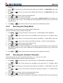
3.6 Measuring Continuity ...................................................................................................................................... 26
3.6.1 Connections ....................................................................................................................................... 26
3.6.2 Threshold resistance level ............................................................................................................... 26
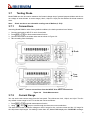
3.7 Testing Diode ................................................................................................................................................... 27
3.7.1 Connections ....................................................................................................................................... 27
3.7.2 Current Range ................................................................................................................................... 27
3.8 Math Functions ................................................................................................................................................ 28
4
ABM-4083
3.8.1 mX+b ................................................................................................................................................... 28
3.8.2 Percent ............................................................................................................................................... 29
3.8.3 dB Calculation.................................................................................................................................... 30
3.8.4 dBm Calculation ................................................................................................................................ 30
Chapter 4 Measurement Options ................................................................. 32
4.1 Measurement configuration ............................................................................................................................. 32
4.1.1 Range ................................................................................................................................................. 32
4.1.2 Filter .................................................................................................................................................... 33
4.1.3 Relative ............................................................................................................................................... 34
4.1.4 Rate ..................................................................................................................................................... 35
4.2 Trigger Operations ........................................................................................................................................... 36
4.2.1 Trigger model ..................................................................................................................................... 36
4.2.2 Reading Hold ..................................................................................................................................... 38
4.2.3 EXT Trig & VM Comp ....................................................................................................................... 39
4.3 Buffer Operations ............................................................................................................................................ 40
4.3.1 Storing Reading ................................................................................................................................. 40
4.3.2 Recalling Readings ........................................................................................................................... 40
4.3.3 Buffer statistics .................................................................................................................................. 41
4.4 Limit Operations .............................................................................................................................................. 41
4.4.1 Enabling limits.................................................................................................................................... 41
4.4.2 Setting Limit Values .......................................................................................................................... 42
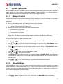
4.5 System Operations ........................................................................................................................................... 43
4.5.1 Beeper Control .................................................................................................................................. 43
4.5.2 Save Settings ..................................................................................................................................... 43
4.5.3 Restore Settings ................................................................................................................................ 44
4.5.4 Display Control .................................................................................................................................. 44
4.5.5 Key Sound .......................................................................................................................................... 45
4.5.6 Self-test............................................................................................................................................... 45
4.5.7 Calibration .......................................................................................................................................... 46
Chapter 5 Remote Operation ....................................................................... 47
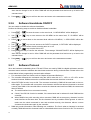
5.1 Selecting an interface ....................................................................................................................................... 47
5.1.1 USB ..................................................................................................................................................... 47
5.1.2 RS-232 ................................................................................................................................................ 47
5.1.3 GPIB .................................................................................................................................................... 48
5.2 RS-232 Interface Operation ............................................................................................................................. 48
5.2.1 RS-232 Connection .......................................................................................................................... 48
5.2.2 Sending and receiving data ............................................................................................................. 50
5.2.3 Selecting Baud Rate ......................................................................................................................... 50
5.2.4 Selecting the Parity Mode ................................................................................................................ 51
5.2.5 Selecting the Terminal Character.................................................................................................... 51
5.2.6 Software Handshake ON/OFF ........................................................................................................ 52
5.2.7 Software Protocol .............................................................................................................................. 52
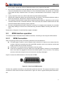
5.3 GPIB interface operation ................................................................................................................................. 53
5.3.1 GPIB Connection .............................................................................................................................. 53
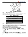
5.3.2 GPIB Interface Capability................................................................................................................. 54
5
ABM-4083
5.3.3 GPIB Addressing ............................................................................................................................... 54
5.3.4 General Bus Commands .................................................................................................................. 55
5.4 Data Format ..................................................................................................................................................... 55
Chapter 6 SCPI Command Reference ......................................................... 56
6.1 Command structure.......................................................................................................................................... 56
6.2 Command Syntax ............................................................................................................................................ 56
6.2.1 Commands and command parameters ......................................................................................... 56
6.2.2 Short-form Rules ............................................................................................................................... 58
6.2.3 Basic Rules of Command Structure ............................................................................................... 58
6.2.4 Multiple Command Rules ................................................................................................................. 59
6.2.5 Command Path Rules ...................................................................................................................... 59
6.3 Command Reference ....................................................................................................................................... 59
6.3.1 SCPI Signal Oriented Measurement Commands ........................................................................ 59
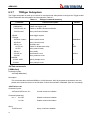
6.3.2 DISPlay subsystem ........................................................................................................................... 62
6.3.3 CALCulate Subsystem ..................................................................................................................... 63
6.3.4 SENSe subsystem command ......................................................................................................... 70
6.3.5 SYSTem Subsystem ......................................................................................................................... 83
6.3.6 UNIT Subsystem ............................................................................................................................... 85
6.3.7 TRIGger Subsystem ......................................................................................................................... 88
6.3.8 R Subsystem...................................................................................................................................... 91
6.3.9 Common Commands........................................................................................................................ 91
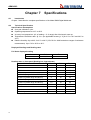
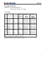
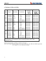
Chapter 7 Specifications ............................................................................... 92
Chapter 8 Program Examples .................................................................... 101
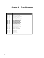
Chapter 9 Error Messages ......................................................................... 104
6
ABM-4083
Chapter 1
General Information
Thanks very much for choosing and using our product. If you have any questions after reviewing this
manual, please contact your local representative or call directly to our application engineers for further
consultation.
1.1
Feature Overview
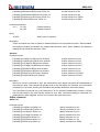
ABM-4083 is a 6½ digital multimeter with high accuracy, stability and speed. The digital multimeter provides
a maximum measurement speed of 1000 readings/sec. DDM has a 0.0035% DC voltage basic accuracy,
0.01% basic resistance accuracy and other high performance. DMM has broad measurement ranges:
DC voltage from 0.1μV to 1000V
AC (RMS) voltage from 0.1μV to 750V, or about 1000V Peak
DC current from 10nA to 12A
AC (RMS) current from 10nA to 12A
Two and four-wire resistance from 0.1mΩ to 120MΩ
Frequency from 5Hz to 1MHz
Some additional capabilities of Model DMM:
Full range of functions: In addition to those listed above, The DMM functions include period, dB,
dBm, continuity, diode testing, mX+b and percent.
Programming languages and remote control interfaces: The DMM provides the SCPI programming language and three remote control interface ports: USB Device, IEEE-488/GPIB (optional)
and RS-232C (optional).
Reading and setup storage: Up to 512 readings and 10 sets of settings can be stored and retrieved.
Closed-cover calibration: The digital multimeter can be calibrated either from the front panel or
through the remote control interface.
1.2
Operating Environment
Power supply: 110V/220V ±10%
Line frequency: 50Hz / 60Hz ±5%
Power consumption: <20VA
Operating temperature: 0℃ to 40℃
Humidity: ≤ 90%RH
1.3
Dimensions and Weight
Dimensions(W×H×D):225mm×100mm×355mm
Net weight: Around 2.5kg
7
ABM-4083
1.4
The
Safety symbols and Precautions
symbol on the instrument indicates that user should refer to the operating instructions located in
the manual before performing.
The
symbol on the instrument shows that high voltage may be present on the terminal(s). Be careful
to avoid personal contact with these voltages.
The symbol
on the instruments means earth grounding.
The WARNING heading used in the manual explains high voltage danger that might result in personal injury
or death. Always read the associated information very carefully before performing the indicated procedure.
The CAUTION heading in the manual reminds user that hazards could damage the instruments if not according to operating instructions. Such damage may invalidate the warranty.
1.5
Incoming Inspection
The DMM was carefully inspected mechanically and electrically before shipment. After unpacking all items
from the shipping carton, please check for any obvious signs of physical damage that may have occurred
during transportation. Report any damage to the shipping agent immediately. Save the original packing
carton for possible future reshipment. The following items are included with every Model DMM order:
Model DMM 61/2 Digital Multimeter
Test leads
Power cord
Two 500mA fuses
Two 1A fuses
Operation Manual
Quality and warranty certificate
Test report
Other optional accessories if ordered
Verify that you have received all the items above when you get the digital multimeter. If anything is missing,
please contact our representative or our sales office.
Note:
8
IEEE-488 and RS232C interface is optional, additional order is needed.
ABM-4083
1.6
Warranty
Aktakom warrants this product to be free from defects in material and workmanship for a period of 2 years
from the date of shipment. During the warranty period, we will, at our option, either repair or replace any
product that proves to be defective.
1.7
Limitation of Warranty
This warranty does not apply to defects resulting from product modification without our express written
consent, or misuse of any product or part. This warranty also does not apply to fuses, software, or problems
arising from normal wear or failure to follow instructions.
9
ABM-4083
Chapter 2
2.1
DMM Overview
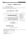
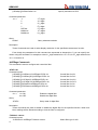
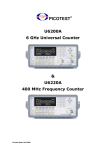
Front Panel Summary
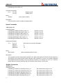
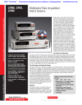
The front panel of the DMM is shown in Figure 2-1. This figure includes some important abbreviated information that should be reviewed before operating the instrument.
Figure 2-1
1.
2.
3.
Measurement function keys (shifted and unshifted)
Select measurement function: DC voltage and current, AC voltage and current, 2-wire and 4-wire resistance, frequency, period, continuity and diode test.
Math function keys
Select the math function: mX+b, %, dB, dBm and Rel.
Menu operation keys
Shift →
10
DMM Front Panel
Open/Close menu
ABM-4083
Shift →
Recall the menu performed last time.
Move through selections within menu level, command level or parameter level
Move through selections within menu level, command level or parameter level.
Move up a level.
Move down a level.
Auto (ENTER)
Save the change made on “parameter” level, and return to the “command” level.
Trig (ESC)
Cancel the change made on “parameter” level, and return to the “command” level.
4. Range and measurement speed keys
5.
6.
Auto
Select a higher range and disable auto ranging.
Select a lower range and disable auto ranging.
Toggle between auto ranging and manual ranging.
Shift →
Set measurement speed to Fast.
Shift →
Set measurement speed to Medium.
Shift → Auto
Trig/Hold Key
Trig
Shift → Trig
Set measurement speed to Slow.
Trigger a measurement from the front panel.
Hold a stable reading on the display when selected numbers of samples are within
the selected tolerance.
Shift/Local keys
Shift
Used to access shifted keys.
Shift (LOCAL)
Cancel GPIB or RS232C remote control mode and back to the LOCAL mode.
2.2
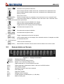
Annunciators on Screen
* (asterisk)
(Diode)
Figure 2-2 Display Annunciators
Reading being stored
Instrument is in diode testing function
(Speaker)
4W
ADRS
AUTO
ERR
FAST
FILT
HOLD
MATH
MED
Beeper on for continuity testing function
Digital multimeter is in 4-wire resistance function.
Digital multimeter is addressed to listen or talk over the GPIB interface
Auto ranging enabled
Hardware or remote control error detected
Fast reading rate
Digital filter enabled
Reading HOLD is enabled
A math operation is enabled (mX+b, %, dB, dBm).
Medium reading rate
11
ABM-4083
MEM
REL
RMT
SHIFT
SLOW
TRIG
2.3
Turns on when reading memory is enabled
Relative reading displayed
Digital multimeter is in remote control mode
Accessing shifted keys
Slow reading rate
Digital multimeter is waiting for an external trigger (front panel or bus).
Front Panel Menu Reference
A:MEASurement MENU
1:CONTINUITY → 2:FILTER → 3:FILT TYPE → 4:FILT COUNT
1.
2.
3.
4.
CONTINUITY
FILTER
FILT TYPE
FILT COUNT
Select the continuity beeper threshold: 1Ω to 1000Ω.
Enable or disable FILTER function.
Select the moving average or repeating average type of filter.
Set the number of readings to be filtered or averaged.
B:MATH MENU
1:SET M → 2:SET B → 3:PERCENT → 4:dB REF → 5:dBm REF → 6:LIMIT TEST → 7:HIGH LIMIT →
8:LOW LIMIT→ 9:LIMIT BEEP
1. SET M
Set the scale factor M for MX+B function.
2. SET B
Set the offset factor B for MX+B function.
3. PERCENT
Set the reference value for PERCENT function.
4. dB REF
Set the dB reference voltage value.
5. dBm REF
Set the dBm reference impedance value.
6. LIMIT TEST
Enable or disable the limit testing.
7. HIGH LIMIT
Set the high limit for limit testing.
8. LOW LIMIT
Set the low limit for limit testing.
9. LIMIT BEEP
Set the beep mode for limit testing.
C:TRIGger MENU
1:READ HOLD → 2:READ COUNT → 3:TRIG MODE → 4:TRIG DELAY
1. READ HOLD
Set the reading hold sensitivity band.
2. READ COUNT
COUNT of readings for reading hold.
3. TRIG MODE
Select INTernal, MANUal or BUS trigger source mode.
4. TRIG DELAY
Select AUTO or MANUal trigger delay mode and specify a time interval
which is inserted before a measurement for the MANUal trigger delay mode.
D:SYStem MENU
1:RDGS STORE → 2:RDGS COUNT → 3:SAVED RDGS → 4:BEEP →5:SAVE CNFG
→ 6:LOAD CNFG → 7:DISPLAY → 8:KEY SOUND → 9:TEST
1. RDGS STORE
Enable or disable reading memory.
2. RDGS COUNT
Set the number of readings to be saved (2 to 512).
3. SAVED RDGS
Recall readings stored in memory.
12
ABM-4083
4.
5.
6.
7.
8.
9.
BEEP
SAVE CNFG
LOAD CNFG
DISPLAY
KEY SOUND
TEST
Enable or disable the beeper function
Save the present configuration as one of the 10 user’s settings.
Restore factory or one of the 10 user’s settings
Enable or disable the front panel display.
Enable or disable the key sound when you press a key.
Perform a complete self-test.
E:Input / Output MENU
1:GPIB ADDR → 2:INTERFACE → 3:BAUD RATE→ 4:PARITY→ 5:TX TERM→ 6:RETURN
1. GPIB ADDR
Set the GPIB bus address (0 to 31)
2. INTERFACE
Select one between GPIB and USB as the remote control interface.
3. BAUD RATE
Select the baud rate for RS-232C (USB) operation.
4. PARITY
Select the parity mode for RS-232C (USB)
5. TX TERM
Select the terminal character for RS-232C (USB) communication
6. RETURN
Enable or disable the command characters RETURN function.
F:CALibration MENU 1
1:SECURED → [1:UNSECURED] → [2:CALIBRATE] → 3:CAL DATE → 4:CAL COUNT
1. SECURED
The digital multimeter is secured against calibration; Enter code to unsecure.
2. UNSECURED
The digital multimeter is unsecured for calibration; Enter code to secure.
3. CALIBRATE
Perform complete calibration of present function when UNSECURED.
4. CAL DATE
Read the date for the latest calibration.
5. CAL COUNT
Read the total number of times the digital multimeter has been calibrated.
1
The commands enclosed in square brackets ([ ]) are “hidden” unless the digital multimeter is UNSECURED for calibration.
13
ABM-4083
2.4
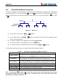
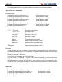
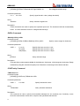
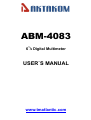
Front Panel Menu Overview
The menu is organized in a top-down tree structure with three levels (menus, commands and parameters)
as shown in Figure 2-3. You can use down (
) or up (
) to move menu tree from one level to another.
) or right
Each of the three levels has several horizontal choices which you can view by using left (
).
(
Menus
Commands
Parameters
Figure 2-3
Shift →
Menu Tree
To turn on the menu, press
To turn off the menu, press Shift →
top row of front panel keys.
To confirm a change on the “parameter” level, press Auto (ENTER).
To cancel a change on the “parameter” level, press Trig (ESC).
To recall the last menu command that was executed, press Shift →
(Menu).
(Menu), or press any of the function or math keys on the
(Recall)
The messages displayed during menu operation are listed in following Table 2-1.
Table 2-1
Messages Displayed During Menu Operation
MESSAGES
DESCRIPTION
CHANGE SAVED
The change made on the “parameter” level is saved. This message will be
displayed after you press Auto (ENTER) to execute the command.
TOO SMALL
The value you specified on the “parameter” level is too small for the selected command. The minimum value allowed is displayed for you to edit.
TOO LARGE
The value you specified on the “parameter” level is too large for the selected command. The maximum value allowed is displayed for you to edit.
FILE SAVING
System configuration file is being saved.
FILE LOADING
System configuration file is being restored.
SAVE SUCCEED
System configuration file is successfully saved.
LOAD SUCCEED
System configuration file is successfully restored.
Note: If you press
on the “menu” level, this is the top level of the menu and you cannot go
on the “parameter” level, this is the bottom level of the
any higher; similarly if you press
menu and you cannot go any lower.
14
ABM-4083
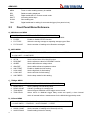
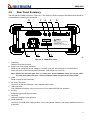
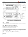
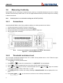
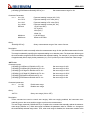
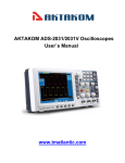
2.5
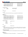
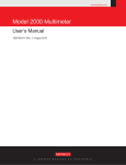
Rear Panel Summary
The rear panel of DMM is shown in Figure 2-4. This section includes important information that should be
reviewed before operating the instrument.
8
7
6
GPI B
VM Comp
5
Ext Tr i g
4
USB
RS- 232C
5V Max t o
20VA Max
!
S/ N: W
1- 508- 00008
RATI NG
~ 110V/ 60Hz
~ 220V/ 50Hz
1
2
Figure 2-4
WARNI NG
※. TO AVOI D ELECTRI C SHOCK,
THE POWER CORD PROTECTI VE GROUNDI NG CONDUCTOR
MUST BE CONNECTED TO GROUND.
FUSE
※. THI S
I NSTRUMENT CONTAI NS NO OPERATOR
SERVI CEABLE PARTS I NSI DE;
REFER SERVI CI NG TO SERVI CE TRAI NED PERSONNEL ONLY.
T1AL
T500mAL
3
Fi
DMM Rear Panel
1. Grounding
Chassis Grounding terminal
2. Power-Line Fuse-Holder Assembly
DMM can be configured for line voltage of 110/220V±10% AC at line frequency of 50/60Hz±5%.
Power-line fuse is used for instrument protection. (220V/500mA or 110V/1A)
Note: Please use the same-type fuse or contact your nearest Aktakom sales and service office.
To verify and replace the fuse, remove the power cable and pull out the fuse holder.
3. Label
Serial number for this instrument
4. RS-232C Connector
Connector for RS-232 operation. Use a standard DB-9 cable.
5. USB Connector
This USB device interface can be connect to a PC to replace the RS-232 operation.
6. Ext Trig
External trigger signal input terminal.
7. VM Comp
Voltmeter complete output terminal
8. GPIB (Optional)
Connector for GPIB (IEEE-488) operation. This is an optional interface; user needs additional order if it
is required.
15
ABM-4083
2.6
2.6.1
Power up
Power Line Connection
Follow the procedure below to connect the DMM to line power and turn on the instrument.
1.
Check to make sure that the line voltage is in the range of 198V to 242V (or 110V±10%) and line frequency is in the range of 47.5 to 52.5Hz (or 60Hz±5%) before connecting the power cord.
CAUTION: Operating the instrument on an incorrect voltage may cause damage to the instrument,
possibly voiding the warranty.
2.
3.
Before plugging in the power cord, make sure that the front panel power switch is in the off position.
Connect the female end of the supplied power cord to the AC receptacle on the rear panel. Connect the
other end of the power cord to a grounded AC outlet.
WARNING: The power cord supplied with the Model DMM contains a separate ground wire for use
with grounded outlets. When proper connections are made, instrument chassis is connected to power line ground through the ground wire in the power cord. Failure to use a
grounded outlet may result in personal injury or death due to electric shock.
4.
Turn on the instrument by pressing the front panel power switch and get ready for measuring.
2.6.2
Power-up Sequence
On power-up, Model DMM performs self-tests on its EPROM and RAM and lights all segments and annunciators for about 1 second. If a failure is detected, the instrument momentarily displays an error message
and the ERR annunciator turns on.
If the instrument passes self-tests, the firmware revision levels are displayed.
2.6.3
High Energy Circuit Safety Precautions
To optimize safety when measuring voltage in high energy distribution circuits, read and use the directions
in the following warning.
WARNIG:
Dangerous arcs of an explosive nature in a high energy circuit can cause severe personal injury or death .If the digital multimeter is connected to a high energy circuit
when set to a current range, low resistance range, or any other low impedance range,
the circuit is virtually shorted. Dangerous arcing can result even when the digital multimeter is set to a voltage range if the minimum voltage spacing is reduced in the external connections.
When making measurements in high energy circuits, use test leads and accessories that meet the following
requirements:
Test leads and accessories must be fully insulated.
Only use test leads that can be connected to the circuit (e.g., alligator clips, spade lugs, etc.) for
hands-off measurements.
Do not use test leads or accessories that decrease voltage spacing. This diminishes arc protection
16
ABM-4083
and creates a hazardous condition.
Use the following sequence when measuring high energy circuits:
1. De-energize the circuit using the regular installed connect-disconnect device, such as a circuit
breaker, main switch, etc.
2. Attach the test leads to the circuit under test. Use appropriate safety rated test leads for this application.
3. Set the digital multimeter to the proper measurement function and range.
4. Energize the circuit using the installed connect-disconnect device and make measurements
without disconnecting the digital multimeter.
5. De-energize the circuit using the installed connect-disconnect device.
6. Disconnect the test leads from the circuit under test.
WARNING: The maximum common-mode voltage (voltage between INPUT LO and the chassis
ground) is 500V peak. Exceeding this value may cause a breakdown in insulation, creating a shock hazard.
2.6.4
Power-on Defaults
Model DMM uses the factory default settings for the power-on settings.
Since the basic measurement procedures in this manual assume the factory defaults, reset the instrument
to the factory settings when following step-by-step procedures. Table 2-2 lists the factory default settings.
17
ABM-4083
Table 2-2
Factory Default Settings
Setting
Autozero
Buffer
Continuity
Beeper
Digits
Rate
Threshold
Current (AC and DC)
Digits(AC)
Digits(DC)
Filter
Count
Mode
Range
Relative
Value
Rate (AC)
Rate (DC)
Diode test
Digits
Range
Rate
Frequency and Period
Digits
Range
Relative
Value
Rate
Function
GPIB
Address
Language
Limits
Beeper
High limit
Low limit
mX+b
Scale factor
Offset
Percent
Reference
18
Factory Default
On
No effect
On
4 1/2
Fast (0.1 PLC)
10Ω
5 1/2
5 1/2
On
10
Moving average
Auto
Off
0.0
Medium (10 PLC)
Medium (1 PLC)
5 1/2
1mA
Medium (1 PLC)
5 1/2
10V
Off
0.0
Medium (0.1 sec)
DCV
No effect
8
SCPI
Off
ON
+1
-1
Off
1.0
0.0
Off
1.0
ABM-4083
Table 2-2
Resistance (2-wire and 4-wire)
Digits
Filter
Count
Mode
Range
Relative
Value
Rate
RS-232 (USB)
Baud
Triggers
Continuous
Delay
Source
Voltage (AC and DC)
dB reference
dBm reference
Digits (AC)
Digits (DC)
Filter
Count
Mode
Range
Relative
Value
Rate (AC)
Rate (DC)
2.6.5
Factory Default Settings (cont.)
5 1/2
On
10
Moving average
Auto
Off
0.0
Medium (1 PLC)
On
9600
On
Auto
Immediate
No effect
75Ω
5 1/2
5 1/2
On
10
Moving average
Auto
Off
0.0
Medium (10 PLC)
Medium (1 PLC)
Warm-up time
Model DMM is ready for use as soon as the power-up sequence has completed. However, to achieve rated
accuracy and stability, allow the instrument to warm up for half an hour. If the instrument has been subjected to extreme temperatures, allow additional time for internal temperatures to stabilize.
2.7
Display
The display of Model DMM is primarily used to display readings, along with the units and type of measurement. Annunciators located on the left, right and bottom indicate various states of operation. See section
2.2 for a complete listing of annunciators.
19
ABM-4083
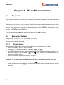
Chapter 3
3.1
Basic Measurements
Preparation
One of the first things you would like to do with your digital multimeter is to become acquainted with its front
panel. We have provided some exercises in foregoing chapters about preparations for use and operations
of front panel.
The front panel has two rows of keys to select various functions and operations. Most keys have a shifted
function printed in blue above the key. To perform a shifted function, press Shift (the Shift annunciator will
turn on). Then, press the key that has the desired label above it. For example, to select the AC current
function, press Shift then press ACV (ACI).
If you accidentally press
3.2
Shift, just press it again to turn off the Shift annunciator.
Measuring Voltage
Voltage ranges: 100 mV, 1 V, 10 V, 100 V, 1000 V (750 VAC)
Maximum resolution: 0.1μV (on 100mV range)
AC technique: true RMS, ac-coupled.
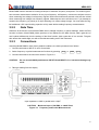
3.2.1
Connections
Assuming Model DMM is under factory default conditions, the basic procedure is as follows:
1. Connect test leads to INPUT HI and LO terminals.
2. Select DC or AC voltage measurement by pressing DCV or ACV.
3. Press Auto toggles auto ranging. Notice the AUTO annunciator is displayed with auto ranging. If you
want manual ranging, use the RANGE
and
keys to select a measurement range consistent with expected voltage.
4. Connect test leads to the sources as shown in Figure 3-1.
CAUTION: Do not apply more than 1000V peak to the input or instrument damages may occur.
5. If the “OVR.FLW” message is displayed, press the up
key to select a higher range until a normal
reading is displayed (or press Auto key for auto ranging). Use the lowest possible range for the best
resolution.
6. Take readings from the display.
20
ABM-4083
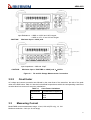
Input Resistance = 10MΩ on 1000V and 100V ranges;
> 10GΩ on 10V, 1V and 100 mV ranges
CAUTION:
Maximum Input = 1010V peak
Input Impedance = 1MΩ and 100pF
CAUTION:
Maximum Input = 750V RMS or 1000V peak, 3×10⁷V.Hz
Figure 3-1
3.2.2
DC and AC Voltage Measurement Connections
Crest factor
AC voltage and current accuracies are affected by the crest factor of the waveform, the ratio of the peak
value to the RMS value. Table 3-1 lists the fundamental frequencies at which the corresponding crest factor
must be taken into account for accuracy calculations.
Table 3-1
3.3
Crest Factor Limitations
Crest Factor
Fundamental Frequency
2
3
4-5
50kHz
3kHz
1kHz
Measuring Current
Model DMM current measurement range: 10 mA, 100 mA (DC only), 1A, 10A
Maximum resolution: 10nA (on 10 mA range)
21
ABM-4083
Note:
3.3.1
See the previous discussion about crest factor in Voltage Measurement in this section
Connections
Assuming Model DMM is under factory default conditions, the basic procedure is as follows:
1. Connect test leads to INPUT LO and SENSE LO terminals
2. Select DCI or ACI measurement function by pressing Shift → DCV or Shift → ACV
3. Press Auto toggles auto ranging. Notice the AUTO annunciator is displayed with auto ranging. If you
and
keys to select a measurement range consistent
want manual ranging, use the RANGE
with expected current.
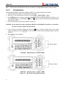
4. Connect test leads to the source as shown in Figure 3-2:
CAUTION: Do not apply more than 2A between INPUT LO and SENSE LO terminals, or the protective fuse on the front panel will open-circuit.
key to select a higher range until a normal
5. If the “OVR.FLW” message is displayed, press up
reading is displayed (or press Auto key for auto ranging). Use the lowest possible range for the best
resolution.
6. Take readings from the display.
CAUTION:
Maximum Input = 1A DC or RMS
CAUTION: Maximum Input = 12A DC or RMS
Figure 3-2 DC and AC Current Measurements
22
ABM-4083
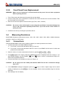
3.3.2
Front Panel Fuse Replacement
WARNING: Make sure the instrument is disconnected from the power line and other equipment
before replacing the fuse.
1. Turn off the power and disconnect the power line and test leads.
2. From the front panel, use a screwdriver to rotate the fuse carrier several turns counter-clockwise. Take
the fuse carrier out of the socket.
3. Remove the fuse and replace it with the same type (T2AL, 250V, 5×20mm).
CAUTION:
Do not use a fuse with a higher current rating than specified or instrument damage may
occur. If the instrument repeatedly blows fuses, try to find out the reason before replacing the fuse.
4. Install the new fuse by reversing the procedure above.
3.4
Measuring Resistance
Model DMM Resistance measurement range: 100Ω, 1kΩ, 10kΩ, 100kΩ, 1MΩ, 10MΩ, 100MΩ; Maximum
resolution: 100μΩ (on 100Ω range)
3.4.1
Connections
Assuming Model DMM is under factory default conditions, the basic procedure is as follows:
1. Connect test leads to the Model DMM as follows:
A: For Ω2-wire, connect the test leads to INPUT HI and LO.
B: For Ω4-wire, connect the test leads to INPUT HI and LO, and SENSE Ω 4W HI and LO. Kelvin test
probes are recommended.
2. Select Ω 2-wire or Ω 4-wire measurement function by pressing Ω2W or Shift → Ω2W .
3. Press Auto toggles auto ranging. Notice the AUTO annunciator is displayed with auto ranging. If you
and
keys to select a measurement range conwant manual ranging, use the RANGE
sistent with expected resistance.
4. Connect test leads to the resistance as shown in Figure 3-3:
CAUTION:
Do not apply more than 1000V peak between INPUT HI and LO or instrument damage
may occur.
key to select a higher range until a normal
5. If the “OVR.FLW” message is displayed, press up
reading is displayed (or press Auto key for auto ranging). Use the lowest possible range for the best
resolution.
6. Take readings from the display.
23
ABM-4083
Note:
Source current flows from the INPUT HI to INPUT LO terminals
Note:
Source current flows from the INPUT HI to INPUT LO terminals
Figure 3-3
3.4.2
Two- and Four- wire Resistance Measurements
Shielding
To achieve a stable reading, it helps to shield resistances greater than 100kΩ. Place the resistance in a
shielded enclosure and connect the shield to the INPUT LO terminal of the instrument electrically.
3.5
Measuring Frequency and Period
Model DMM frequency measurement range: 5 Hz to more than 1MHz.
Model DMM period measurement range: 0.2s to less than 1μs.
Input signal range: 100 mV AC to 750V AC RMS.
The instrument uses the volts input terminals to measure frequency. The AC voltage range can be changed
with the RANGE
full-scale range.
3.5.1
and
keys. However, the signal voltage must be greater than 10% of the
Trigger Level and Measurement Errors
Frequency and Period apply a zero-crossing trigger, meaning that a count is taken when the signal crosses
the zero level.
24
ABM-4083
Model DMM uses an interactive counting technique to measure frequency and period. This method generates constant measurement resolution for any input frequency. All frequency counters are subject to errors
when measuring low-voltage, low-frequency signals. Both internal noise and external noise are also critical
when measuring low-voltage, low-frequency signals. Measurement errors will also occur if you attempt to
measure the frequency (or period) of an input following a dc offset voltage change. You must allow the digital multimeter’s DC input blocking capacitor to fully settle before making frequency measurements.
3.5.2
Gate Time
Gate time is the amount of time Model DMM uses to sample frequency or period readings. When the Fast
function is chosen, Model DMM yield a gate time of ten millisecond, the Med function yield a gate time of
one hundred millisecond, thus the settings of the Slow function yield a gate time of one second. The gate
time affects the usable digits, as well as the ultimate reading rate of the instrument.
3.5.3
Connections
Assuming Model DMM is under factory default conditions, the basic procedure is as follows:
1. Connect test leads to INPUT HI and LO terminals.
2. Select frequency or period measurement functions by pressing
Freq or Shift → Freq
3. Connect test leads to the source as shown in Figure 3-4:
CAUTION:
Do not exceed 1000V peak between INPUT HI and INPUT LO or instrument damage may
occur.
4. Taking a reading from the display
Input Impedance =1MΩ in parallel with <100pF
CAUTION: Maximum Input = 750 RMS, or 1000V Peak
Figure 3-4 Frequency and Period Measurements
25
ABM-4083
3.6
Measuring Continuity
Model DMM uses the 1kΩ range to measure circuit continuity. A threshold resistance level (1Ω to 1000Ω)
should be set and factory default value is 10Ω. The digital multimeter alerts you with a beep when a reading
is below the set level.
Note:
3.6.1
Continuity has a non-selectable reading rate of FAST (0.1 PLC).
Connections
Assuming Model DMM is under factory default conditions, the basic procedure is as follows:
1. Connect test leads to the INPUT HI and LO terminals.
2. Select Continuity measurement function by pressing Cont .
3. Connect test leads to the resistance under test as shown in Figure 3-5.
4. Take a reading from the display
Note:
3.6.2
Source current flows from the INPUT HI to INPUT LO terminals.
Figure 3-5 Continuity Measurement
Threshold resistance level
You can define a threshold resistance from 1Ω to 1000Ω. Factory default value is 10Ω. Follow the steps
below to define the resistance level:
1. Press Cont for Continuity Measurement.
2. Press Shift →
to enter the command level, “1: CONTINUITY” will be displayed.
3. Press
to enter the parameter level, the current LEVEL value will be displayed.
and
keys to choose a numerical place and use
and
keys to increment
4. Use
or decrement the digits. Enter a value from 1 to 1000.
5. Press Auto (ENTER) to confirm your setting. Message “CHANGE SAVED” will be displayed for a moment.
6. Press Cont or Shift →
26
to exit the menu and return to the continuity measurement.
ABM-4083
3.7
Testing Diode
Model DMM can also be used to measure the forward voltage drop of general-purpose diodes and the zener voltage of zener diodes. A current range (10mA, 100μA or 10μA) can be selected for diode measurement.
Note: Diode test has a non-selectable reading rate of Medium (1 PLC)
3.7.1
Connections
Assuming Model DMM is under factory default conditions, the basic procedure is as follows:
1. Connect test leads to INPUT HI and LO terminals.
2. Press Shift → Cont for diode measurement function.
3. Connect test leads to the diode under test as shown in Figure 3-6.
4. Take a reading from the display.
Note:
3.7.2
Source current flows from the INPUT HI to INPUT LO terminals
Figure 3-6 Diode Measurement
Current Range
You can set the test current range from the front panel. The choices are 1mA, 100μA, and 10μA. The factory default current range is 1mA. To set the test current as follows:
1. Press Shift → Cont for diode measurement function
and
keys to scroll through the three test current selections.
2. Using
The diode test function measures voltage on the 3V range for the 1mA test current and the 10V range for
the 100μA and 10μA ranges. If a reading is more than 10V, Model DMM displays the “OVR.FLW” message.
27
ABM-4083
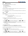
3.8
Math Functions
Model DMM math operations are divided into four categories:
mX+b and percent
dB and dBm calculations
Statistics of buffered readings
Limit testing
The first two categories are discussed here; buffered reading statistics and reading limit testing are described in the next chapter – Measurement Options
Notes: Once enabled for a function, the mX+b and percentage calculations are in effect across
function changes.
3.8.1
mX+b
This math operation lets you manipulate normal display readings (X) mathematically according to the following calculation:
Y = mX + b
Where: X is the normal display reading
m and b are user-entered constants for scale factor and offset
Y is the displayed result
To configure the mX+b calculation, perform the following steps:
1. Press mX+b for mX+b math operation and the present scale factor M will be displayed:
M:+1.000000
2. Use the
and
keys to choose a numerical place and use
and
keys to increment or decrement the digits. Enter a value and units prefix.
3. Press Auto (ENTER) to confirm the M value and the message “CHANGE SAVED” will be displayed for
a moment and then the present B value will be displayed.
B:+0.000000 m
4. Enter a value and units prefix.
5. Press Auto (ENTER) to confirm the B value, “CHANGE SAVED” will be displayed.
6. DMM returns back to the measurement status and displays the results of calculations.
If you want to change the M and B parameter values after enabling the math function, besides the foregoing
method you can take actions as below:
1. Press Shift →
, “1: SET
M” will be displayed (Command level).
2. Press
key to enter the parameter level and the present scale factor M will be displayed:
M: +1.000000 .
3. Use the
and
keys to choose a numerical place and use
and
keys to increment or decrement the digits. Enter a value and units prefix.
4. Press Auto (ENTER) to confirm the M value and the message “CHANGE SAVED” will be displayed for
28
ABM-4083
a moment and then DMM returns back to the command level. Press Trig (ESC) to cancel the M value
input, DMM returns back to the command level without changing the M value.
5. Press
, “2: SET B” will be displayed (Command level).
key to enter the parameter level and the present offset factor B will be displayed:
6. Press
B: +00.00000 m.
7. Use the
and
keys to choose a numerical place and use
and
keys to increment or decrement the digits. Enter a value and units prefix.
8. Press Auto (ENTER) to confirm the B value. The message “CHANGE SAVED” will be displayed for a
moment and then DMM returns back to the command level. Press Trig (ESC) to cancel the B value
input, DMM returns back to the command level without changing the B value.
9. Press Shift →
3.8.2
to exit the menu operation, and return back to the mX+b math operation status.
Percent
If the percent calculation is selected, a reference value must be specified. The displayed reading will be expressed as percent deviation from the reference value. The percentage calculation is performed as follows:
Where:
Input is the normal display reading
Reference is the user-entered constant
Percent is the displayed result
To configure the percent calculation, perform the following steps:
1. Press Shift → Rel
for percent math operation and the present reference value displays:
REF:+1.000000
2. Use
and
keys to choose a numerical place and use
and
keys to increment
or decrement the digits. Enter a value and units prefix.
3. Press Auto (ENTER) to confirm the reference value. The message “CHANGE SAVED” will be displayed
for a moment.
4. DMM will display the result of the percent calculation.
If you want to change the parameter values when the percent math function is enabled, besides the foregoing method you can take actions as below:
1. Press Shift →
to enter the command level, “3: PERCENT” will be displayed.
2. Press
to enter the parameter level, and the present reference value will be displayed:
REF: +1.000000 .
3. Use
and
keys to choose a numerical place and use
and
keys to increment
or decrement the digits. Enter a value and units prefix.
4. Press Auto (ENTER) to confirm the reference value, “CHANGE SAVED” will be displayed for a moment,
and DMM will return to the command level. Press Trig (ESC) to cancel the reference value input,
DMM returns back to the command level without changing the reference value.
5. Press Shift →
key to exit the menu and return to the percent math operation status.
29
ABM-4083
Model DMM will display measurement result of calculation. If the value of “Input” is larger than that of
“Reference”, displayed result will be positive; contrarily, it will be negative if the value of “Input” is smaller
than that of “Reference”.
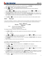
3.8.3
dB Calculation
Expressing DC and AC voltage in dB makes it possible to compress a large range of measurements into a
much smaller scope. The relationship between dB and voltage is defined by the following equation:
Where: VIN is the DC or AC input signal
VREF is the specified voltage reference level
The instrument will read 0dB when the reference voltage level is applied to the input.
If a relative value is in effect when dB is selected, this relative value will be converted to dB value before
REL is applied. If REL is applied after dB function has been selected, dB has REL applied to it directly.
To set the reference voltage, perform the following steps:
1. Press Shift + mX+b for dB math operation and the present reference value is displayed:
REF:+0.000000
and
keys to choose a numerical place and use
and
keys to increment
2. Use
or decrement the digits. Enter a value and units prefix.
3. Press Auto (ENTER) to confirm the reference voltage, the message “CHANGE SAVED” will be displayed for a moment. DMM returns back to the measurement status.
4. DMM will display the result of the dB calculation.
If you want to change the parameter values when dB function is in effect, you can take actions as below:
1. Press Shift →
to enter the command level, “4: dB REF “ will be displayed.
2. Press
to enter the parameter level, and the present reference value will be displayed:
REF: +1.000000 .
3. Use
and
keys to choose a numerical place and use
and
keys to increment
or decrement the digits. Enter a value and units prefix.
4. Press Auto (ENTER) to confirm the reference value, the message “CHANGE SAVED” will be displayed
for a moment, and DMM will return to the command level. Press Trig (ESC) to cancel the reference
value input, DMM returns back to the command level without changing the reference value.
5. Press Shift →
key to exit the menu and return to the dB math operation status.
Notes: The dB calculation takes the absolute value of the ratio VIN/VREF. The largest negative value
of dB is -160dB. This will accommodate a ratio of VIN = 1uV, VREF = 1000V.
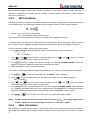
3.8.4
dBm Calculation
dBm is defined as decibels above or below a 1mW reference. With an user-programmable reference impedance,
Model DMM reads 0dBm when the voltage needed to dissipate 1mW through the reference impedance is applied.
30
ABM-4083
The relationship between dBm, reference impedance, and the voltage is defined by the following equation:
Where: VIN is the DC or AC input signal voltage value. ZREF is the specified reference impedance.
If a relative value is in effect when dBm is selected, the relative value will be converted to dBm value before
REL is applied. If REL is applied after dBm has been selected, dBm has REL applied to it directly.
To set the reference impedance, perform the following steps:
1. Press Shift →mX+b, the voltage reference value for dB math function will be displayed.
2. Press Auto (ENTER) to confirm the voltage reference value, now you have selected the dB math function.
3. Press Shift → mX+b again, the present impedance reference value for dBm math function will be displayed: REF:0000
and
keys to choose a numerical place and use
and
keys to increment
4. Use
or decrement the digits. Enter a value from 1Ω to 9999Ω.
5. Press Auto (ENTER) to confirm the reference impedance, the message “CHANGE SAVED” will be
displayed for a moment. DMM returns back to the measurement status.
6. DMM will display the result of the dBm calculation.
If you want to change the impedance reference value after the dBm function is enabled, you can take actions as below:
1. Press Shift →
to enter the command level, “5: dBm REF “ will be displayed.
2. Press
to enter the parameter level, and the present impedance reference value will be displayed:
REF: 0000.
3. Use
and
keys to choose a numerical place and use
and
keys to increment
or decrement the digits. Enter a value from 1Ω to 9999Ω.
4. Press Auto (ENTER) to confirm the reference value, the message “CHANGE SAVED” will be displayed
for a moment, and DMM will return to the command level. Press Trig (ESC) to cancel the reference
value input, DMM returns back to the command level without changing the reference value.
5. Press Shift →
key to exit the menu and return to the dB math operation status.
NOTES: The reference impedance and input impedance mentioned in this chapter are totally different. Input impedance is inherent in the instrument and could not be changed via foregoing methods.
dBm is valid for both positive and negative DC voltage.
The mX+b and percent math operations are applied after the dBm or dB math. For example,
if mX+b is selected with m=10 and b=0, the display will read 10.000MXB for a 1VDC signal.
If dBm is selected with (ZREF = 50Ω), the display will read 130MXB.
31
ABM-4083
Chapter 4
Measurement Options
This chapter provides description of the front panel features of DMM. For those measurement options accessible only by a remote interface, refer to Chapter 5 and 6. This chapter is organized as follows:
Measurement Configuration – Describes Ranging, Filtering, Relative readings, Digits of
Resolution and Measurement rate
Triggering operations – Explains trigger sources and trigger delay
Buffer operations – Discusses the reading storage buffer and buffer statistics
Limit operations – Defines how to set reading limits
System Operations – Provides details on setup saving and restoring, instrument self-test and
calibration
4.1
Measurement configuration
The following paragraphs discuss configuring digital multimeter for making measurement.
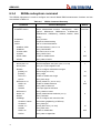
4.1.1
Range
You can let the digital multimeter automatically select the range using auto ranging or you can select a fixed
range using manual ranging. Auto ranging is convenient because the digital multimeter automatically selects the appropriate range for each measurement. However, you can use manual ranging for faster
measurements since the digital multimeter doesn’t have to determine which range to use for each measurement. The digital multimeter returns back to auto ranging when power has been off or after a remote
interface reset.
Maximum readings
The full scale readings for every range on each function are 20% over range except for the 1000VDC,
750VAC and diode test ranges.
Manual ranging
or
To select a range, simply press
selected range is displayed for a moment.
key. The instrument changes one range per key press. The
If the instrument displays the “OVR.FLW” message on a particular range, select a higher range until an
on-range reading is displayed. Use the lowest range possible without causing an overflow to ensure best
accuracy and resolution.
Autoranging
To enable autoranging, press Auto key. The AUTO annunciator turns on when autoranging is selected.
While autoranging is selected, the instrument automatically chooses the best range to measure the applied
signal. However, autoranging should not be used when optimum speed is required.
Note that up-ranging occurs at 120% of the range, while down-ranging occurs at 10% of normal range.
32
ABM-4083
To cancel autoranging, press Auto or
instrument on the present range.
or
key. Pressing Auto to cancel autoranging leaves the
The Auto key has no effect on the continuity and diode test functions.
4.1.2
Filter
FILTER lets you set the filter response to stabilize noisy measurements. Model DMM uses a digital filter.
The displayed, stored and transmitted readings are simply an average of a number of reading conversions
(from 1 to 100).
Perform the following steps to select a filter:
1. Press Shift →
2. Press
displayed.
to enter the menu on the menu level, “A: MEAS MENU” will be displayed.
to move down to the command level within the MESA MENU, “1: CONTINUITY” will be
3. Use
or
be displayed.
key to move across to the Filter Command on the command level, “2: FILTER” will
4. Press
to move down a level to the filter parameter choice.
or
to select ON or OFF choice.
5. Using
6. Press Auto (ENTER) to confirm the choice. The message “CHANGE SAVED” will be displayed to show
that the change is now in effect. DMM automatically exits the parameter level and moves up a level to
the command level.
to move across to the filter type command on the command level, “3: FILT TYPE” will be
7. Use
displayed.
8. Press
to move down a level to the filter type parameter choice.
or
to select MOVNG AV or REPEAT filter type.
9. Using
10. Press Auto (ENTER) to confirm the choice. The message “CHANGE SAVED” will be displayed to show
that the change is now in effect. DMM automatically exits the parameter level and moves up a level to
the command level.
to move across to the filter count command on the command level, “4: FILT COUNT” will be
11. Use
displayed.
12. Press
to move down a level to edit the filter count parameter.
and
keys to choose a numerical place and use
and
keys to increment
13. Use
or decrement the digits. Enter a filter count from 1 to 100.
14. Press Auto (ENTER) to confirm the count value. The message “CHANGE SAVED” will be displayed to
show that the change is now in effect. DMM automatically exits the parameter level and moves up a
level to the command level.
15. Press Shift →
key to exit from the menu and return to the measurement status.
16. The FILT annunciator turns on when the filter function enabled.
NOTE: The filter can be set for any measurement function except frequency, period, continuity and
diode test.
33
ABM-4083
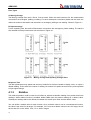
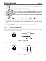
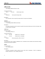
Filter Types
A: Moving Average
The Moving average filter uses a first-in, first-out stack. When the stack becomes full, the measurement
conversions are averaged, yielding a reading. For each subsequent conversion placed into the stack, the
oldest conversion is discarded, and the stack is re-averaged, yielding a new reading. Shown in Figure 4-1.
B: Repeat average
For the repeating filter, the stack is filled and the conversions are averaged to yield a reading. The stack is
then cleared and the process starts over as shown in Figure 4-1.
Figure 4-1
Moving average and repeating average filters
Response Time
The filter parameters have speed and accuracy tradeoffs for the time needed to display, store, or output a
filtered reading. These affect the number of reading conversions for speed versus accuracy and responder
to input signal change.
4.1.3
Relative
The relative operation could be used to null offsets or subtract a baseline reading from present and future
readings. When relative function is enabled, Model DMM uses the present reading as a relative value.
Subsequent readings will be the difference between the actual input value and the relative value.
You can define a relative value for each function. Once a relative value is set for a measurement function,
the value is the same for all ranges. For example, if 2V is set as a relative value on the 10V range, the relative is also 2V on the 1000V, 100V, 1V or 100mV ranges.
34
ABM-4083
Additionally, when you perform a zero correction for DCV, Ω2 or Ω4 measurements by enabling REL, the
displayed offset becomes the reference value. Subtracting the offset from the actual input zeroes the display, as follows:
Displayed reading = Actual Input – Reference
Select a range that cannot accommodate the relative value does not cause an overflow condition, but it also
does not increase the maximum allowable input for that range. For example: on the 1V range, Model DMM
still overflows for a 1.2V input.
To set a REL value, press Rel when the display shows the value you want as the relative value. The REL
annunciator turns on. Press Rel a second time to disable REL.
You can also input a REL value manually using the mX+b function. Set M for 1 and B for any value you want.
Please refer to Chapter 3 for details about mX+b function.
4.1.4
Rate
The RATE operation sets the integration time of the A/D converter, the period of time the input signal is
measured. The integration time affects the usable digits, the amount of reading noise, as well as the ultimate reading rate of the instrument. The integration time is specified in parameters based on a number of
power line cycles (NPLC), where 1 PLC for 50Hz is 20msec.
In general, the fastest integration time (FAST (0.1 PLC) set from the front panel or remote interface) results
in increased reading noise and fewer usable digits, while the slowest integration time (10 PLC) provides the
best common-mode and normal-mode rejection. In-between settings are a compromise between speed and
noise.
The RATE parameters are explained as follows:
Fast
FAST sets integration time to 0.1 PLC. Use FAST if speed is of primary importance, however it is at the
expense of increased reading noise and fewer usable digits.
Medium
Medium sets integration time to 1 PLC. Use Medium when a compromise between noise performance and
speed is acceptable.
Slow
Slow sets integration time to 10 PLC. SLOW provides better noise performance at the expense of speed.
For the AC functions (ACV, ACI), Rate setting determines the bandwidth setting as below:
· Fast
500Hz~100kHz.
· Medium
50Hz~100kHz.
· Slow
5Hz~100kHz.
35
ABM-4083
Note:
4.2
The integration time can be set for any measurement function except continuity (FAST) and
diode test (MEDium).
Trigger Operations
The digital multimeter’s triggering system allows you to generate triggers either manually or automatically or
externally and take multiple readings per trigger. The following paragraphs discuss front panel triggering,
the programmable trigger delay and the reading hold feature.
4.2.1
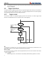
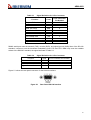
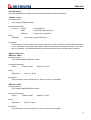
Trigger model
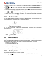
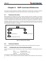
The flowchart of Figure 4-2 summarizes triggering process of the instrument. It is called a trigger model
because it is modeled after the SCPI commands used to control triggering.
I ni t i at e Tr i gger i ng
MEASur e?
READ?
I NI Ti at e
Tr i gger sour ce
I dl e
st at e
Wai t f or
Tr i gger
I MMedi at e
BUS
MAN
Del ay
Measur ement
sampl e
sampl e
Tr i gger
count ≠ 1 count ≠1
Figure 4-2
Trigger model
Idle
The instrument is considered to be in the idle state whenever it is not performing any measurement. Once
Model DMM is taken out of idle, operation proceeds through the flowchart.
Wait for Trigger
The control source holds up operation until the programmable event occurs and is detected. See description below for trigger sources:
Immediate
With this trigger source, event detection is immediately satisfied allowing operation to continue.
36
ABM-4083
External
Event detection is satisfied for both kinds of triggers as below:
1. A bus trigger (*TRG) command is received.
2. The front panel Trig key is pressed (DMM must be taken out of remote before it will
respond to Trig key).
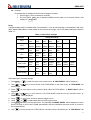
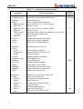
Delay
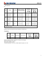
A programmable delay is available after event detection. It can be set manually or automatically. With Auto
delay, Model DMM selects a delay based on the function and range. The AUTO delay settings are listed in
Table 4-1.
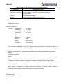
Table 4-1 Auto delay settings
Function
Range and Delay
DCV
100mV
1ms
1V
1ms
10V
1ms
100V
5ms
1000V
5ms
ACV
100mV
400ms
1V
400ms
10V
400ms
100V
400ms
750V
400ms
FREQ
100mV
1ms
1V
1ms
10V
1ms
100V
1ms
750V
1ms
DCI
10mA
2ms
100mA
2ms
1A
2ms
10A
2ms
ACI
10mA
400ms
1A
400ms
10A
400ms
Ω2W, Ω4W
100Ω
3ms
10kΩ
13ms
100kΩ
25ms
100uA
1ms
10uA
1ms
1kΩ
3ms
Continuity
1kΩ
3ms
Diode testing
1mA
1ms
1MΩ
100ms
10MΩ
150ms
100MΩ
250ms
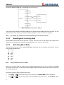
Take steps below for delay settings:
1. Press Shift →
to enter the menu on the menu level, “A: MEAS MENU” will be displayed.
2. Use
or
be displayed.
key to move across to the TRIG MENU on the menu level, “C: TRIG MENU” will
3. Press
displayed.
to move down to the command level within the TRIG MENU, “1: READ HOLD” will be
4. Use
or
key to move across to the TRIG MODE command on the command level, “3:
TRIG MODE” will be displayed.
5. Press
to move down a level to select a trigger source.
or
to select IMM, MAN or BUS trigger source.
6. Using
7. Press Auto (ENTER) to confirm the choice. The message “CHANGE SAVED” will be displayed to show
that the change is now in effect. DMM automatically exits the parameter level and moves up a level to
the command level.
8. Use
to move across to the TRIG DELAY command on the command level, “4: TRIG DELAY” will
37
ABM-4083
be displayed.
9. Press
to move down a level to set the type of delay mode.
or
to select AUTO or MANU delay mode.
10. Using
11. Press Auto (ENTER) to confirm the choice. The message “CHANGE SAVED” will be displayed to show
that the change is now in effect. If AUTO mode is chosen, DMM will exit the parameter level and move
up a level to the command level.
12. If MANU mode is chosen, DMM requires you to continue to specify the delay time. The present delay
time will be displayed.
DELAY: 0000mS
and
keys to choose a numerical place and use
and
keys to increment
13. Use
or decrement the digits. Enter a value of delay time (from 0 to 6000ms).
14. Press Auto (ENTER) to confirm the choice. The message “CHANGE SAVED” will be displayed to show
that the change is now in effect. DMM automatically exits the parameter level and moves up a level to
the command level.
15. Press Shift →
Note:
key to exit from the menu and return to the measurement status.
Changing the delay to MANUAL on one function changes the delays on all functions to
MANUAL.
Measurement Sample
The primary device action is a measurement. However, the device action block could include the following
additional actions:
Filtering — If the repeating filter is enabled, the instrument samples the specified number of reading conversions to yield a single filtered reading. Only one reading conversion is performed if the filter is disabled,
or after the specified number of reading conversions for a moving average filter is reached. The output of
filter feeds hold function.
Hold — Withhold enabled, the first processed reading becomes the “Seed” reading and operation loops
back within the measurement sample block. After the next reading is processed, it is checked to see if it is
within the selected window (0.01%, 0.1%, 1%, 10%) of the “seed” reading. If the reading is within the window, operation again loops back within the measurement sample block. This looping continues until the
specified number (2-100) consecutive readings are within the window. If one of the readings is not within the
window, the instrument acquires a new “seed” reading and the hold process continues.
4.2.2
Reading Hold
When a hold reading is acquired as described in “Measurement Sample”, an audible beep is sounded (if
enabled) and the reading is considered a “true measurement”. The reading is held on the display until an
“out of window” reading occurs to restart the hold process. The reading hold feature allows you to capture
and hold a stable reading on the display.
Take steps below to enable and set reading hold function.
1. Press Shift + Trig to enable reading hold function
2.
Press Shift →
to enter the menu on the menu level, “A: MEAS MENU” will be displayed.
3.
Use
key to move across to the TRIG MENU on the menu level, “C: TRIG MENU” will
38
or
ABM-4083
be displayed.
4.
Press
displayed.
5.
6.
7.
Press
to move down a level to select a window percentage.
or
key to select a window percentage (0.01%, 0.1%, 1%, 10%).
Use
Press Auto (ENTER) to confirm the selection. The message “CHANGE SAVED” will be displayed to
show that the change is now in effect. DMM automatically exits the parameter level and moves up a
level to the command level.
8.
to move across to the READ COUNT command on the command level, “2: READ COUNT”
Use
will be displayed.
to move down to the command level within the TRIG MENU, “1: READ HOLD” will be
9. Press
to move down a level to enter a count value. (Default count is 5)
and
keys to choose a numerical place and use
and
keys to increment
10. Use
or decrement the digits. Enter a value of count (from 2 to 100).
11. Press Auto (ENTER) to confirm the count. The message “CHANGE SAVED” will be displayed to show
that the change is now in effect. DMM will exit the parameter level and move up a level to the command
level.
12. Press
4.2.3
Shift →
key to exit from the menu and return to the measurement status.
EXT Trig & VM Comp
Input a negative effective pulse to trigger the instrument through the Ext Trig input terminal, when the trigger
mode is set to EXT as shown in Figure 4-3 below.
Ext Vrig
Iutput
5 V
0 V
>1μs
Figure 4-3
Trigger model
When the instrument finishes its present measurement, a Voltmeter Complete output signal will be outputted as shown in Figure 4-4 below.
Output
VM Comp
5 V
0 V
Approximately
2μs
Figure 4-4
Trigger model
39
ABM-4083
4.3
Buffer Operations
Model DMM has a buffer to store from 2 to 512 readings and units. In addition, recalled data includes statistical information, such as minimum, maximum, average and standard deviation.
The buffer fills with the requested number of readings and stops. Readings are placed in the buffer after any
math operations are performed. Buffered data is overwritten each time the storage operation is selected.
The data is volatile; it is not saved through a power cycle.
The following paragraphs will discuss storing and recalling buffered data.
4.3.1
Storing Reading
Select a measurement function and connect the test leads to the signal under test first. Then use the following procedure to store readings:
1. Set up the instrument for the desired configuration
2.
Press Shift →
to enter the menu on the menu level, “A: MEAS MENU” will be displayed.
3.
Use
or
displayed.
key to move across to the SYS MENU on the menu level, “D: SYS MENU” will be
4.
Press
displayed.
5.
6.
7.
Press
to move down a level to set RDGS STORE function.
or
key to set reading store function to ON or OFF.
Use
Press Auto (ENTER) to confirm the ON/OFF selection. The message “CHANGE SAVED” will be displayed to show that the change is now in effect. DMM automatically exits the parameter level and
moves up a level to the command level.
8.
to move across to the RDGS COUNT command on the command level, “2: RDGS COUNT”
Use
will be displayed.
to move down to the command level within the SYS MENU, “1: RDGS STORE” will be
9. Press
to move down a level to edit the number for storing.
and
keys to choose a numerical place and use
and
keys to increment
10. Use
or decrement the digits. Enter a number for storing (from 2 to 512).
11. Press Auto (ENTER) to confirm the number for storing. The message “CHANGE SAVED” will be displayed to show that the change is now in effect. DMM will exit the parameter level and move up a level
to the command level.
12. Press Shift →
key to exit from the menu and return to the measurement status.
13. The asterisk (*) annunciator turns on to indicate a data storage operation. It will turn off when the
storage is finished.
4.3.2
Recalling Readings
Use the following steps to recall stored readings and buffer statistics:
1.
Press Shift →
to enter the menu on the menu level, “A: MEAS MENU” will be displayed.
2.
Use
or
displayed.
key to move across to the SYS MENU on the menu level, “D: SYS MENU” will be
40
ABM-4083
3.
Press
displayed.
to move down to the command level within the SYS MENU, “1: RDGS STORE” will be
4.
Use
or
displayed.
5.
Press
to move down a level to view the stored readings. “MEM” annunciator turns on. If there is
no reading stored, “BUFFER EMPTY” will be displayed for a moment.
6.
Use
7.
Use the function keys or press Shift →
or
key to move across to the SAVED RDGS command, “3: SAVED RDGS” will be
key to navigate through the reading numbers, reading values, and statistics.
to exit from the menu and return to the measurement
status.
4.3.3
Buffer statistics
The MAX and MIN values are the maximum and minimum values in the buffer. The AVR value is the mean
of the buffered readings. The equation used to calculation the mean is:
is a stored reading
n is the number of stored readings
The STD value is the standard deviation of the buffered readings. The equation used to calculate the
standard deviation is:
Where:
Where:
4.4
is a stored reading
n is the number of stored readings.
Limit Operations
Limit operations set and control the values that determine the HI / IN / LO status of subsequent measurements. Limits can be applied to all measurement functions except continuity. The limit test is performed after
mX+b and percent math operations. Unit prefixes are applied before the limit test, for example:
Low Limit = -1.0, High Limit = 1.0
A 150mV reading equals 0.15V (IN).
Low Limit = -1.0, High Limit = 1.0
A 0.6kΩ reading equals 600Ω (HI)
You can configure the digital multimeter to beep or not when readings are out of the limit range.
4.4.1
Enabling limits
Use the following procedure to turn on the limit operation:
1.
Press
Shift →
to enter the menu on the menu level, “A: MEAS MENU” will be displayed.
41
ABM-4083
2.
Use
or
be displayed.
3.
Press
played.
4.
Use
played.
5.
6.
Press
to move down a level to set LIMIT TEST function to ON.
Press Auto (ENTER) to confirm the set of LIMIT TEST function. The message “CHANGE SAVED” will
be displayed to show that the change is now in effect. DMM will exit the parameter level and move up a
level to the command level.
7.
Press Shift →
8.
When the digital multimeter returns to the normal display, the HI/IN/LO status is displayed along with
the reading.
4.4.2
key to move across to the MATH MENU on the menu level, “B: MATH MENU” will
to move down to the command level within the MATH MENU, “1: SET M” will be disor
key to move across to the LIMIT TEST command, “6: LIMIT TEST” will be dis-
key to exit from the menu and return to the measurement status.
Setting Limit Values
Use the following steps to enter high and low limit values:
1.
Press Shift →
to enter the menu on the menu level, “A: MEAS MENU” will be displayed.
2.
Use
or
be displayed.
key to move across to the MATH MENU on the menu level, “B: MATH MENU” will
3.
Press
played.
4.
Use
played.
5.
Press
to move down a level to input the high limit value. The present high limit value will be
displayed:
HI: +1.000000
6.
Use
and
keys to choose a numerical place and use
and
keys to increment
or decrement the digits. Enter an expected value for high limit.
Press Auto (ENTER) to confirm the value of high limit. The message “CHANGE SAVED” will be displayed to show that the change is now in effect. DMM will exit the parameter level and move up a level
to the command level.
7.
8.
Use
played.
9.
Press
played:
to move down to the command level within the MATH MENU, “1: SET M” will be disor
or
key to move across to the HIGH LIMIT command, “7: HIGH LIMIT” will be dis-
key to move across to the LOW LIMIT command, “8: LOW LIMIT” will be dis-
to move down a level to input the low limit value. The present low limit value will be disLO: -1.000000
10. Use
and
keys to choose a numerical place and use
and
keys to increment
or decrement the digits. Enter an expected value for low limit.
11. Press Auto (ENTER) to confirm the value of low limit. The message “CHANGE SAVED” will be displayed to show that the change is now in effect. DMM will exit the parameter level and move up a level
to the command level.
12. Press Shift →
42
key to exit from the menu and return to the measurement status.
ABM-4083
4.5
System Operations
Model DMM has some other operations. Beeper control, saving and restoring setup information, front panel
display control, key sound control, self-test and calibration. These information is not directly related to
making measurements but is an important part of operating the digital multimeter.
4.5.1
Beeper Control
Normally, the multimeter will emit a tone whenever certain conditions are met. For example: the multimeter
will beep when a stable reading is captured in reading hold. You may want to disable the beeper for certain
applications.
When you disable the beeper, the multimeter will not emit a tone when:
1. A limit is exceeded in a limit test
2. A stable reading is captured in reading hold.
Disabling the beeper has no effect on the tone generated when:
1. An internal error is generated.
2. The continuity threshold is exceeded.
3. A front panel key is pressed.
The beeper state is stored in non-volatile memory and does not change when power has been off or
after a reset. The beeper is enabled when the digital multimeter is shipped from the factory.
Use the following steps to change the beeper’s state:
1.
Press Shift →
to enter the menu on the menu level, “A: MEAS MENU” will be displayed.
2.
Use
or
displayed.
key to move across to the SYS MENU on the menu level, “D: SYS MENU” will be
3.
Press
displayed.
4.
5.
6.
7.
Use
or
key to move across to the BEEP command, “4: BEEP” will be displayed.
to move down a level to set the beeper control.
Press
or
key to select ON or OFF.
Use
Press Auto (ENTER) to confirm the beeper control. The message “CHANGE SAVED” will be displayed
to show that the change is now in effect. DMM will exit the parameter level and move up a level to the
command level.
8.
Press Shift →
4.5.2
to move down to the command level within the SYS MENU, “1: RDGS STORE” will be
key to exit from the menu and return to the measurement status.
Save Settings
Model DMM allows user to save the present settings. These settings are saved as files in non-volatile
memory (Maximum 10 files can be stored: FILE-0 – FILE-9). Files will not be lost when power has been off
or after a rest. User can restore the settings from the files when power on. Please refer to chapter 2 for
factory default settings about saved file content.
To save present settings as user’s setting, please follow steps below:
1.
Press Shift →
to enter the menu on the menu level, “A: MEAS MENU” will be displayed.
43
ABM-4083
2.
Use
or
displayed.
3.
Press
displayed.
4.
Use
played.
5.
6.
7.
Press
to move down a level to select a file to save.
or
key to select a file from FILE-0 to FILE-9.
Use
Press Auto (ENTER) to save the present setting to the selected file. The message “FILE SAVING” and
“SAVE SUCCEED” will be displayed. DMM will exit the parameter level and move up a level to the
command level.
8.
Press Shift →
4.5.3
key to move across to the SYS MENU on the menu level, “D: SYS MENU” will be
to move down to the command level within the SYS MENU, “1: RDGS STORE” will be
or
key to move across to the SAVE CNFG command, “5: SAVE CNFG” will be dis-
key to exit from the menu and return to the measurement status.
Restore Settings
Use the following steps to restore factory default setting (Described in Chapter 2) or user saved configuration (FILE-0 to FILE-9):
1.
Press Shift →
to enter the menu on the menu level, “A: MEAS MENU” will be displayed.
2.
Use
or
displayed.
key to move across to the SYS MENU on the menu level, “D: SYS MENU” will be
3.
Press
displayed.
4.
Use
played.
5.
6.
Press
to move down a level to select a file to restore.
or
key to select the factory default setting or user saved configuration (FILE-0 to
Use
FILE-9).
Press Auto (ENTER) to restore the selected setting. The message “FILE LOADING” and “LOAD
SUCCEED” will be displayed. DMM will exit the parameter level and move up a level to the command
level.
7.
8.
to move down to the command level within the SYS MENU, “1: RDGS STORE” will be
or
Press Shift →
4.5.4
key to move across to the LOAD CNFG command, “6: LOAD CNFG” will be dis-
key to exit from the menu and return to the measurement status.
Display Control
To speed up measurement rate for remote control, Model DMM allows user to turn off the front panel display.
You can also turn on the front panel display at remote control.
When the front panel display is turned off, readings are not sent to the display and some display annunciators still can be displayed. Front panel operation is unaffected by turning off the display.
The display is enabled when power has been off or after a remote interface reset.
Use following steps for display control settings:
1.
44
Press Shift →
to enter the menu on the menu level, “A: MEAS MENU” will be displayed.
ABM-4083
2.
Use
or
displayed.
3.
Press
displayed.
4.
5.
6.
7.
Use
or
key to move across to the DISPLAY command, “7: DISPLAY” will be displayed.
to move down a level to set the display control.
Press
or
key to select ON or OFF for the front panel display.
Use
Press Auto (ENTER) to confirm the selection. The message “CHANGE SAVED” will be displayed to
show that the change is now in effect. DMM will exit the parameter level and move up a level to the
command level.
8.
Press Shift →
4.5.5
key to move across to the SYS MENU on the menu level, “D: SYS MENU” will be
to move down to the command level within the SYS MENU, “1: RDGS STORE” will be
key to exit from the menu and return to the measurement status.
Key Sound
To avoid mis-operation, Model DMM has key sound function and you can enable or disable it. Factory default setting is enabled. The key sound state is stored in non-volatile memory and does not change when
power has been off or after a reset.
Use following steps for key sound setting:
1.
Press Shift →
to enter the menu on the menu level, “A: MEAS MENU” will be displayed.
2.
Use
or
displayed.
key to move across to the SYS MENU on the menu level, “D: SYS MENU” will be
3.
Press
displayed.
4.
Use
played.
5.
6.
7.
Press
to move down a level to enable or disable the key sound.
or
key to turn ON or turn OFF the key sound.
Use
Press Auto (ENTER) to confirm the selection. The message “CHANGE SAVED” will be displayed to
show that the change is now in effect. DMM will exit the parameter level and move up a level to the
command level.
8.
Press Shift →
4.5.6
to move down to the command level within the SYS MENU, “1: RDGS STORE” will be
or
key to move across to the KEY SOUND command, “8: KEY SOUND” will be dis-
key to exit from the menu and return to the measurement status.
Self-test
The system Self-test is used as diagnostic tools to locate problems quickly for maintenance man.
A power-on self-test occurs automatically when you turn on Model DMM to assure you that the digital multimeter is operational. Power-on self-test is only part of self-test and does not include analog circuit self-test.
Please refer to maintenance guide for the use and relative information about self-test.
45
ABM-4083
4.5.7
Calibration
To make sure the instrument could achieve the designed performance, re-calibration and verification is required at least once a year. Instrument calibration could be performed either via the calibration menu from
the front panel or through a remote control interface.
The CAL MENU can be used to view the calibration date, to view the number of times calibration has been
performed and to perform calibration. Some of the items are password-protected to prevent accidental or
unauthorized calibration of the digital multimeter.
Note:
To prevent destroying the calibration data stored in non-volatile memory, only the authorized service center or qualified individual can do the instrument calibration with desired
equipment.
For a more detailed discussion of calibration procedure, please contact the factory or the authorized agency.
46
ABM-4083
Chapter 5
Remote Operation
Besides the front panel control, DMM supports USB device interface, RS-232 serial interface and GPIB
parallel interface for remote control. You can use only one interface at a time. Standard Commands for
Programmable Instruments (SCPI) is fully supported by the USB, RS-232 and GPIB interfaces, however
they use different hardware configurations and communication protocols.
This section includes the following information:
Selecting an interface
USB interface operation.
RS-232 interface operation and reference
GPIB bus operation and reference
5.1
Selecting an interface
Model DMM digital multimeter supports three built-in interfaces:
USB device interface
RS-232 interface
GPIB bus interface (optional)
You can use only one interface at a time. The factory default interface selection is the USB interface. You
can select the interface from the front panel. The interface selection is stored in non-volatile memory. It does
not change when power has been off or after a remote interface reset.
5.1.1
USB
You can operate the USB device interface as if it’s a RS-232 interface from the computer, after the USB
driver is installed. All the instrument setups for RS-232 interface are applicable for the USB interface (or
virtual RS232 interface). Please refer to RS-232 setup and operation.
5.1.2
RS-232
You can connect RS-232 interface with a computer. Some considerations will draw your attention:
You must define the baud rate
You must use the SCPI programming language
Perform the following steps to select RS-232 as the remote interface:
1.
Press Shift →
to enter the menu on the menu level, “A: MEAS MENU” will be displayed.
2.
Use
or
displayed.
key to move across to the I/O MENU on the menu level, “E: I/O MENU” will be
3.
Press
played.
4.
Use
played.
5.
Press
to move down to the command level within the I/O MENU, “1: GPIB ADDR” will be disor
key to move across to the INTERFACE command, “2: INTERFACE” will be dis-
to move down a level to select an interface.
47
ABM-4083
6.
7.
Use
or
key to select USB interface.
Press Auto (ENTER) to confirm the selection. The message “CHANGE SAVED” will be displayed to
show that the change is now in effect. DMM will exit the parameter level and move up a level to the
command level.
8.
Press Shift →
key to exit from the menu and return to the measurement status.
For more information about the RS-232 interface, see section RS-232 interface operation.
5.1.3
GPIB
The GPIB bus is the IEEE-488 interface. You must specify a unique address for the Model DMM digital
multimeter. The factory default address is 8.
Perform the following steps to select GPIB as the remote interface:
1.
Press Shift →
to enter the menu on the menu level, “A: MEAS MENU” will be displayed.
2.
Use
or
displayed.
key to move across to the I/O MENU on the menu level, “E: I/O MENU” will be
3.
Press
played.
4.
Use
played.
5.
6.
7.
Press
to move down a level to select an interface.
or
key to select GPIB interface.
Use
Press Auto (ENTER) to confirm the selection. The message “CHANGE SAVED” will be displayed to
show that the change is now in effect. DMM will exit the parameter level and move up a level to the
command level.
8.
Press Shift →
to move down to the command level within the I/O MENU, “1: GPIB ADDR” will be disor
key to move across to the INTERFACE command, “2: INTERFACE” will be dis-
key to exit from the menu and return to the measurement status.
For more information about the GPIB interface, see section GPIB interface operation.
5.2
RS-232 Interface Operation
The instrument provides various remote commands. All operations from the front panel can be performed
by a computer via the RS-232 interface.
5.2.1
RS-232 Connection
RS232C standard now is widely used as the serial communication standard. RS-232 stands for Recommend Standard number 232 and C is the latest revision of the standard.
The serial ports on most instruments use a subset of the RS232C standard. The full RS232c standard
specifies a 25-pin “D” connector of which 22 pins are used. Most of these pins are not needed for normal
serial communications, and the common RS-232 signals are listed in Table 5-1:
48
ABM-4083
Table 5-1
Signal Definition for 9 Pin Connector
Function
Code
9 Pin Connector
Pin Number
Request To Send
RTS
7
Clear To Send
CTS
8
Data Set Ready
DSR
6
Data Carrier Detect
DCD
1
Data Terminal Ready
DTR
4
Transmitted Data
TXD
3
Received Data
RXD
2
Signal Ground Common
GND
5
DMM’s serial port uses the transmit (TXD), receive (RXD), and signal ground (GND) lines of the RS-232
standard. It does not use the hardware handshaking lines CTS and RTS. DMM only uses the smallest
subset of the RS232C standard, the signal are listed in Table 5-2.
Table 5-2
Signal Definition for 9 Pin Connector
Function
Code
9 Pin Connector Pin Number
Transmitted Data
TXD
3
Received Data
RXD
2
Signal Ground Common
GND
5
Figure 5-1 shows the rear panel connector for the RS-232 interface.
Figure 5-1
Rear Panel RS-232 Interface
49
ABM-4083
Connection between DMM and a computer shown as Figure 5-2:
Figure 5-2 RS-232 Connection Sketch
There may be some difference between DMM RS-232 interface and a standard RS-232C interface. You can
make the connection cable by yourself according the diagram or order one from our company.
Note:
5.2.2
Pin 4 and 6, pin 7 and 8 are shorted respectively at the end of controller.
Sending and receiving data
Model DMM transfers data using 8 data bits, 1 stop bit, and none, even or odd parity. Each program message that is transmitted to the controller is terminated with <LF>, <CR>, or <LF><CR>.
5.2.3
Selecting Baud Rate
The baud rate is the rate at which Model DMM digital multimeter and the computer communicate. Choose
one of these available rates:
38.4k
19.2k
9600
4800
2400
1200
600
Note:
Factory default baud rate is 9600.
Before you choose a baud rate, make sure the programming terminal that you are connecting to the DMM
can support the baud rate you selected. Both the digital multimeter and the other device must be configured
for the same baud rate.
Perform the following steps to select a baud rate:
1.
Press Shift →
to enter the menu on the menu level, “A: MEAS MENU” will be displayed.
2.
Use
key to move across to the I/O MENU on the menu level, “E: I/O MENU” will be
50
or
ABM-4083
displayed.
3.
Press
played.
4.
Use
played.
5.
6.
7.
Press
to move down a level to set the baud rate.
or
key to select a baud rate.
Use
Press Auto (ENTER) to confirm the selection. The message “CHANGE SAVED” will be displayed to
show that the change is now in effect. DMM will exit the parameter level and move up a level to the
command level.
8.
Press Shift →
5.2.4
to move down to the command level within the I/O MENU, “1: GPIB ADDR” will be disor
key to move across to the BAUD RATE command, “3: BAUD RATE” will be dis-
key to exit from the menu and return to the measurement status.
Selecting the Parity Mode
The instrument has three kinds of parity modes: NONE, EVEN, ODD.
Perform the following steps to select a Parity mode:
1.
Press Shift →
to enter the menu on the menu level, “A: MEAS MENU” will be displayed.
2.
Use
or
displayed.
key to move across to the I/O MENU on the menu level, “E: I/O MENU” will be
3.
Press
played.
4.
5.
6.
7.
Use
or
key to move across to the PARITY command, “4: PARITY” will be displayed.
to move down a level to set the parity mode.
Press
or
key to select a parity mode.
Use
Press Auto (ENTER) to confirm the selection. The message “CHANGE SAVED” will be displayed to
show that the change is now in effect. DMM will exit the parameter level and move up a level to the
command level.
8.
Press Shift →
5.2.5
to move down to the command level within the I/O MENU, “1: GPIB ADDR” will be dis-
key to exit from the menu and return to the measurement status.
Selecting the Terminal Character
The instrument has three kinds of terminal characters: <LF>, <CR> and <LF><CR>.
Perform the following steps to select the terminal characters:
1.
Press Shift →
to enter the menu on the menu level, “A: MEAS MENU” will be displayed.
2.
Use
or
displayed.
key to move across to the I/O MENU on the menu level, “E: I/O MENU” will be
3.
Press
played.
4.
Use
or
displayed.
5.
6.
7.
Press
to move down a level to set the terminal character.
or
key to select a terminal character.
Use
Press Auto (ENTER) to confirm the selection. The message “CHANGE SAVED” will be displayed to
to move down to the command level within the I/O MENU, “1: GPIB ADDR” will be diskey to move across to the terminal character command, “5: TX TERM” will be
51
ABM-4083
show that the change is now in effect. DMM will exit the parameter level and move up a level to the
command level.
8.
Press Shift →
5.2.6
key to exit from the menu and return to the measurement status.
Software Handshake ON/OFF
You can enable or disable the software handshake.
Perform the following steps to enable or disable software handshake.
1.
Press Shift →
to enter the menu on the menu level, “A: MEAS MENU” will be displayed.
2.
Use
or
displayed.
key to move across to the I/O MENU on the menu level, “E: I/O MENU” will be
3.
Press
played.
4.
5.
6.
7.
Use
or
key to move across to the PARITY command, “6: RETURN” will be displayed.
to move down a level to set the return on or off.
Press
or
key to select ON or OFF.
Use
Press Auto (ENTER) to confirm the selection. The message “CHANGE SAVED” will be displayed to
show that the change is now in effect. DMM will exit the parameter level and move up a level to the
command level.
8.
Press Shift →
5.2.7
to move down to the command level within the I/O MENU, “1: GPIB ADDR” will be dis-
key to exit from the menu and return to the measurement status.
Software Protocol
Since the hardware handshaking lines CTS and RTS are not used by DMM, the digital multimeter uses the
command return method to eliminate the data losses and errors during communication. Please refer to the
content below before programming communication software.
1. For command syntax and format, refer to Chapter 6 Command Reference.
2. The controller transmits the command using the ASCII code with <LF>, <CR> or <LF><CR> as the
terminal character. DMM executes the command after the terminal character is received.
3. When RETURN function is set to ON. The command received by DMM will be sent back to the controller again. The controller will not send the next character until the last returned character is received
correctly from DMM. If the controller fails to receive the character sent back from DMM, the reasons are
listed as follows:
The serial interface is not connected correctly.
Check if the RS-232 function is enabled, if the same baud rate is selected for both DMM and the
controller.
When DMM is busy with executing a bus command, DMM will not accept any character from the
serial interface at the same time. So the character sent by controller will be ignored. In order to
make sure the whole command is sent and received correctly, the character without a return
character should be sent again by the controller.
4. DMM only sends information under following two conditions. The first is when a character is received
normally; DMM will send the character back as a handshake when return function is ON. The second is
52
ABM-4083
when a query command is received; DMM will send the query response information.
5. Once a query command is received, DMM will send the query response information immediately even
if the rest commands have not been finished. So if the command includes two queries, the controller
should read the query responses twice. One query is recommended to be included in a single command.
6. A query response is sent out in ASCII codes with the preset terminal character.
7. Several query responses will be sent continuously with 1ms interval. The controller should be ready to
receive the responses; otherwise the response information will be lost.
8. The controller should receive the preset query response terminal character. Otherwise you will confuse
a terminal character with a returned character. At the same time the controller should receive the last
returned character before receiving a query response.
9. For some commands that will take a long time to execute, for example reset command, the controller
should keep waiting to avoid the next command being lost when DMM is executing the former command.
Please refer to Chapter 8 for serial interface program examples.
5.3
GPIB interface operation
This section contains information about GPIB bus standard, connecting to and using the GPIB interface.
5.3.1
GPIB Connection
When configuring a GPIB system, the following restrictions must be adhered to.
The total length of cable in one bus system must be less than or equal to two meters times the
number of devices connected on the bus (the GPIB controller counts as one device) and the total
length of cable must not exceed 20 meters.
A maximum of 15 devices can be connected on one bus system.
There are no restrictions on how the cables are connected together. However, it is recommended
that no more than four piggyback connectors be stacked together on any one device. The resulting
structure could exert enough force on the connector mounting to damage it.
Figure 5-3 shows the GPIB interface on the rear panel of DMM.
Figure 5-3 Rear Panel GPIB Interface
To allow many parallel connections to one instrument, stack the connector. Two screws are located on each
connector to ensure that connections remain secure. Figure 5-4 shows a typical GPIB system interconnection.
53
ABM-4083
Figure 5-4
5.3.2
Typical GPIB System Interconnection
GPIB Interface Capability
Table 5-3 lists the DMM’s GPIB capabilities and functions. These functions provide the mean for an instrument to receive, process, and transmit commands, data, and status over the GPIB bus.
Table 5-3
GPIB interface Capability
Code
5.3.3
Function
SH1
Complete Source Handshake capability
AH1
Complete Acceptor Handshake capability
T5
Basic Talker; Talk-Only; Unaddressed if MLA; no serial poll.
L4
Basic Listener; Unaddressed if MTA; no Listen Only.
RL1
Remote/Local capability
DC1
Device Clear capability
DT1
Device Trigger capability
C0
No controller capability
E1
Drivers are open-collector
GPIB Addressing
Model DMM digital multimeter ships from the factory with a GPIB address of 8. You can set the address to a
value of 0 to 30 and the address is saved in the non-volatile memory. Do not assign the same address to
another device or a controller that are on the same GPIB bus system.
Perform the following steps to set the GPIB address of Model DMM digital multimeter:
→
to enter the menu on the menu level, “A: MEAS MENU” will be displayed.
1.
Press
2.
Use
or
displayed.
3.
Press
played.
4.
Use
and
keys to choose a numerical place and use
and
keys to increment
or decrement the digits. Enter an expected value for GPIB address (from 0 to 31).
Press Auto (ENTER) to confirm the address. The message “CHANGE SAVED” will be displayed to
5.
54
Shift
key to move across to the I/O MENU on the menu level, “E: I/O MENU” will be
to move down to the command level within the I/O MENU, “1: GPIB ADDR” will be dis-
ABM-4083
show that the change is now in effect. DMM will exit the parameter level and move up a level to the
command level.
6.
Press Shift →
5.3.4
key to exit from the menu and return to the measurement status.
General Bus Commands
General commands are those commands, such as DCL, that have the same general meaning regardless of
the instrument. Table 5-4 lists the general bus commands along with the programming statement for each
command.
Table 5-4 General bus commands and associated statements
Command
Programming
statement
REM
REMOTE 8
IFC
ABORT 8
Goes into talker and listener idle states
LLO
LOCAL
LOCKOUT
LOCAL keys locked out
GTL
LOCAL 8
DCL
CLEAR
SDC
CLEAR 8
GET
TRIGGER 8
SPE,SPD
SPOLL 8
Effect on Model DMM Digital Multimeter
Goes into effect when next addressed to listen
Cancel remote; Restore front panel operation for the
digital multimeter.
Return all devices to known conditions.
Return the DMM to known condition
Initiates a trigger
Serial Polls the DMM
For SCPI commands, please refer to Chapter 6: SCPI Command reference
5.4
Data Format
DMM outputs the measurement results using the ASCII character string format via the GPIB bus. The data
format is described in the following Figure 5-5.
SD.DDDDDDESDDD<NL>
S: +/D: number 0 to 9
E: exponent sign (“+”is omitted)
<NL>: New Line, ASCII code is 10
Figure 5-5 Data Format
55
ABM-4083
Chapter 6
SCPI Command Reference
This chapter provides descriptions of all DMM's available GPIB commands which correspond to Standard
Commands for Programmable Instruments (SCPI) command sets. Use this chapter as a reference.
6.1
Command structure
DMM commands are divided into two types: common commands and SCPI commands. The common
commands are defined in IEEE std. 488.2-1987, and these commands are common for all devices. Not all
commands are supported by the DMM. The SCPI commands are used to control all of the DMM's functions.
The SCPI commands are tree structured three levels deep. (The highest level commands are called the
subsystem commands in this manual.) So the lower level commands are legal only when the subsystem
commands have been selected. A colon (:) is used to separate the higher level commands and the lower
level commands. See Figure 6-1 for a sample.
SENSe
RESistance
HOLD
RANGe
SENS:RES:RANG 1k
STATe
SENS:HOLD:STAT ON
AUTO
SENS:RES:RANG:AUTO ON
Figure 6-1 Command Tree Example
6.2
Command Syntax
The information in this section covers the syntax for both common commands and SCPI commands.
6.2.1
Commands and command parameters
Common commands and SCPI commands may or may not use a parameter. The following are some examples:
*RST
No parameter used
:FORMat <name> Parameter<name> required
:IMMediate
No parameter used
Put at least one space between the command word and the parameter.
Brackets [ ]: Some command words are enclosed in brackets. These brackets are used to denote an
56
ABM-4083
optional command word that does not need to be included in the program message. For example:
:RANGe[:UPPer] <n>
These brackets indicate that :UPPer is optional and does not have to be used. Thus, the above command can be sent in one of the two ways below:
or
:RANGe <n>
:RANGe:UPPer <n>
NOTICE: When using optional command words in your program, do not include the brackets.
Angel brackets <>: Angle brackets are used to denote a parameter type. Do not include the brackets in
the program message. For example:
:HOLD:STATe <b>
The <b> indicates that a Boolean-type parameter is required. Thus, to enable the HOLD feature, you
must send the command with ON or 1 parameter as below:
or
:HOLD:STATe ON
:HOLD:STATe 1
Parameter types: The following are some of the more common parameter types:
<b>
Boolean: Used to enable or disable an instrument operation. 0 or OFF disables the operation and 1 or ON enables the operation. Example:
:CURRent:AC:RANGe:AUTO
<name>
ON
Name parameter: Select a parameter name from a listed group. Example:
<name> =
MOVing
REPeat
:RESistance:AVERage:TCONtrol
<NRf>
Enable autoranging
MOVing
Numeric Representation format: This parameter is a number that can be expressed as an
integer (e.g., 6), a real number (e.g., 25.3) or an exponent (e.g., 5.6E2). Example:
:MMFactor 5
<n>
Numeric value: A numeric value parameter can consist of a NRf number or one of the
following name parameters: DEFault, MINimum, MAXimum. When DEFault parameter
is used, the instrument is programmed to the *RST default value. When the MINimum
parameter is used, the instrument is programmed to the lowest allowable value. When
57
ABM-4083
the MAXimum parameter is used, the instrument is programmed to the largest allowable
value. Examples:
[:SENSe[1]]:CURRent[:DC]:NPLCycles
[:SENSe[1]]:CURRent[:DC]:NPLCycles
[:SENSe[1]]:CURRent[:DC]:NPLCycles
[:SENSe[1]]:CURRent[:DC]:NPLCycles
6.2.2
1
DEFault
MINimum
MAXimum
Short-form Rules
Use the following rules to determine the short-form version of any SCPI command:
If the length of the command word is four letters or less, no short form version exists. Example:
:AUTO = :AUTO
These rules apply to command words that exceed four letters:
If the fourth letter of the command word is a vowel, delete it and all the letters after it. Example:
:immediate = :imm
Rule exception – The short form version of the following command uses only the first two letters of the
word.
:TCouple = :tc
If the fourth letter of the command word is a consonant, retain it but drop all the letters after it. Example:
:format = :form
If the command contains a question mark (?; query) or a non-optional number included in the command word, you must include it in the short-form version. Example:
:delay? = :del?
Command words or characters that are enclosed in brackets ([ ]) are optional and need not be included
in the program message.
6.2.3
Basic Rules of Command Structure
Letter case (upper and low) is ignored.
For example:
FUNC:VOLT:DC = func:volt:dc = Func:Volt:Dc
Spaces (︺ is used to indicate a space) must not be placed before and/or after the colon (:).
For example:
(wrong) FUNC︺:︺VOLT:DC
58
(right) FUNC: VOLT:DC
The command can be completely spelled out or in abbreviated type. (In the following description, short
form will be printed in upper case.)
For example:
FUNCTION: VOLTAGE:DC = FUNC: VOLT:DC
The command header should be followed by a question mark (?) to generate a query for that command.
For example:
FUNC?
ABM-4083
6.2.4
Multiple Command Rules
The semicolon (;) can be used as a separator to execute multiple commands on a single line. The multiple
command rules are as follows.
Commands at the same level and in the same subsystem command group can be separated by a
semicolon (;) on a multiple command line.
For example:
CALCulate3:LIMit[1]:STATe <b>;STATe?
To restart commands from the highest level, a semicolon (;) must be used as the separator, and then a
leading colon (:), which shows that the restarted command is a command at the top of the command
tree, must follow.
For example:
:CALCulate[1]:FORMat?;:CALCulate[1]:KMATh:MMFactor <NRf>
The GPIB common commands can restart only after a semicolon on a multiple command line.
For example,
CALCulate3:LIMit[1]:STATe <b>;*IDN?
6.2.5
Command Path Rules
Each new program message must begin with the root command, unless it is optional (e.g., [:SENSe]).
If the root is optional, simply treat a command word on the next level as the root.
The colon at the beginning of a program message is optional and need not be used. Example:
:DISPlay:ENABle <b> = DISPlay:ENABle <b>
When the path pointer detects a colon(;), it moves down to the next command level.
When the path pointer detects a colon (:) after a semicolon (;), it resets back to the root level.
The path pointer can only move down. It cannot be moved up a level. Executing a command at a higher
level requires that you start over at the root command.
6.3
Command Reference
Model DMM provides following subsystem commands:
◆ DISPlay
◆ CALCulate ◆ SENSe
◆ SYStem
◆ UNIT ◆ TRIGger ◆ R
Model DMM supports following common commands:
◆ *RST
6.3.1
◆ *TRG
◆ *IDN
SCPI Signal Oriented Measurement Commands
The signal oriented measurement commands are used to acquire readings. You can use these high-level
instructions to control the measurement process. These commands are summarized in Table 6-1.
59
ABM-4083
Table 6-1 Signal Oriented Measurement Command Summary
Command
MEASure:<function>?
:CONFigure:<function>
:FETCh?
:READ?
Function Description
Perform an :ABORt, :CONFigure:<function>, and a :READ?
Configure DMM in a “one-shot” measurement mode for a
specified function.
Request the latest reading.
Perform an :ABORt, :INITiate, and a :FETCh?
MEASure command
Command syntax:
:MEASure:<function>?
Command parameter :
<function> = VOLTage[:DC]
VOLTage:AC
CURRent[:DC]
CURRent:AC
RESistance
FRESistance
FREQuency
PERiod
DIODe
CONTinuity
DC voltage
AC voltage
DC current
AC current
2-wire resistor
4-wire resistor
Frequency
Period
Diode testing
Continuity test
Description:
This command combines all of the other signal oriented measurement commands to perform a
“one-shot” measurement and acquire the reading.
When this command is sent, the following commands execute in the order that they are presented.
:ABORt
:CONFigure:<function>
:READ?
When :ABORt is executed, if continuous initiation is disabled, the instrument goes into the idle state.
If continuous initiation is enabled, the operation re-starts at the beginning of the Trigger Model.
When :CONFigure is executed, the instrument goes into a “one-shot” measurement mode.
When :READ? is executed, its operation will then be performe. In general, another :ABORt is
performed, then an :INITiate, and finally a FETCh? to acquire the reading.
CONFigure Command
Command syntax:
:CONFigure:<function>
60
ABM-4083
Command parameter :
<function> = VOLTage[:DC]
VOLTage:AC
CURRent[:DC]
CURRent:AC
RESistance
FRESistance
FREQuency
PERiod
DIODe
CONTinuity
DC voltage
AC voltage
DC current
AC current
2-wire resistor
4-wire resistor
Frequency
Period
Diode testing
Continuity test
Query:
:CONFigure?
Query the selected function.
Description:
This command configures the instrument for subsequent measurements on the specified function.
Basically, this command places the instrument in a “one-short” measurement mode. You then use
the :READ? command to trigger a measurement and acquire a reading.
When this command is sent, the DMM will be configured as follows:
The function specified by this command is selected.
All controls related to the selected function are defaulted to the *RST values.
Continuous initiation is disabled.
The control source of the Trigger Model is set to Immediate.
The count values of Trigger Model are set to one.
The delay of the Trigger Model is set zero.
All math calculations are disabled.
Buffer operation is disabled. A storage operation currently in process will be aborted.
Autozero is set to the *RST default value.
This command is automatically adderted when the :MEASure? Command is sent.
FETCh? Command
Command syntax:
:FETCh?
Description:
This query command is used to obtain the lastest post-processed reading. This command does not
affect the configuration of the instrument.
This command does not trigger a measurement. The command simply requests the last available
reading. This command continues to return the same old reading, until there is a new reading.
61
ABM-4083
This command will be automatically asserted when :READ? or :MEASure? command is sent.
READ? Command
Command syntax:
:READ?
Description:
Typically, this command is used with the instrument in the “one-shot” measurement mode to trigger and
acquire a specified number of readings. The :SAMPle:COUNt command is used to specify the number
of readings (seeTrigger Subsystem). Note that the readings are stored in the buffer.
When this command is sent, the following commands execute in the order that they are presented:
:ABORt
:INITiate
:FETCh?
When :ABORt is executed, if continuous initiation is disabled, the instrument goes into the idle state. If
continuous initiation is enabled, the operation re-starts at the beginning of the Trigger Model.
If the instrument is in the idle state, :INITiate takes the instrument out of the idle state. If continuous initiation is enabled, (:INITiate:CONTinuous ON), then the :INITiate command generates an error and
ignores the command.
See the :FETCh? command for more details. Note that an “Init ignored” error will not cancel the execution of the :FETCh? command.
NOTE: You cannot use the :READ? command if sample count >1 (see Trigger Subsystem) and
there are readings stored in the buffer (error -225, out of memory). Either set sample
count to one or clear the buffer.
6.3.2
DISPlay subsystem
The DISPlay subsystem commands are mainly used to control the display of the DMM. and are
summarized in Table 6-2.
Table 6-2
Command
:DISPlay
:ENABle <b>
:ENABle?
:ENABle <b>
Command syntax:
:DISPlay:ENABle <b>
62
DISPlay Subsystem Commands Summary
Function Description
Enable or disable front panel dispaly
Query state of the display
ABM-4083
Command Parameter:
<b> = 0 or OFF
1 or ON
Query:
:ENABle?
Disable front panel dislay
Enable front panel display
Query state of the display
Description:
This command is used to enable or disable front panel display circuitry. When disabled, the instrument
operates at a higher speed. While disabled, the display is frozen. All front panel controls except LOCAL
are disabled. Normal display operation can be resumed by using :ENABle command or pressing LOCAL key to enable the display.
6.3.3
CALCulate Subsystem
The commands in this subsystem are used to configure and control the calculate subsystems and are
summarized in Table 6-3.
63
ABM-4083
Table 6-3
Command
64
CALCulate Command Summary
Function Description
:CALCulate[1]
:FORMat <name>
:FORMat?
:KMATh
:MMFactor <NRf>
:MMFactor?
:MBFactor <NRf>
:MBFactor?
:PERCent <NRf>
:ACQuire
:PERCent?
:STATe <b>
:STATe?
:DATA?
Subsystem to control CALC1:
Select math format (NONE,MXB,PERCent)
Query math format.
Path to configure math calculations:
Set “m” factor for mx+b (-100e6 to 100e6)
Query “m” factor
Set “b” factor for mx+b (-100e6 to 100e6)
Query “b” factor
Set target value for PERCent calculation(-100e6 ~100e6)
Use input signal as target value.
Query percent
Enable or disable KMATh calculation
Query state of KMATh calculation
Read result of KMATh calculation
:CALCulate2
:TRACe
:CLEar
:POINts <NRf>
:POINts?
:DATA?
:FORMat <name>
:FORMat?
:STATe <b>
:STATe?
:IMMediate
:IMMediate?
:DATA?
Subsystem to control CALC2
:CALCulate3
:LIMit[1]
:UPPer <n>
:UPPer?
:LOWer <n>
:LOWer?
:STATe <b>
:STATe?
:FAIL?
Subsystem to control CALC3 (limit test):
Path to control LIMIT test:
Set upper limit (-100e6 to 100e6).
Query upper limit.
Set lower limit (-100e6 to 100e6).
Query lower limit
Enable or disable limit test
Query state of limit test
Query test result (1=pass, 0=fail)
Clear readings in the buffer.
Specify the size of buffer (2 to 512)
Query buffer size.
Read all readings in the buffer.
Select Math format.
Query math format.
Enable or disable calculation
Query state of math function
Recalculate raw input date in buffer
Perform calculation and read result
Read math result of CALC2
Default
Parameter
PERCent
1
0
1
NONE
1
-1
OFF
ABM-4083
:CALCulate[1]
Use these commands to configure and control MXB and percent math calculations.
:FORMat <name>
Command syntax:
:CALCulate[1]:FORMat <name>
Command Parameter:
<name> = NONE
No calculations
MXB
Polynomial math calculation
PERCent
Percent math calculation
Query:
:FORMat?
Query programmed math format
Description:
This command is used to specify the format for the CALC1 math calculations. With NONE selected, no
CALC1 calculation is performed. With MXB or PERCent selected and enabled, the result of the calculation is displayed. The calculated reading is refreshed every time the instrument takes a reading.
:KMATh Commands
:MMFactor <NRf>
Command syntax:
:CALCulate[1]:KMATh:MMFactor <NRf>
Command Parameter:
<NRf> =
-100e6 to 100e6
Query:
:MMFactor?
Specify “m” factor.
Query “m” factor.
Description:
This command is used to define the “m” factor for the mx+b calculation.
:MBFactor <NRf>
Command syntax:
:CALCulate[1]:KMATh:MBFactor <NRf>
Command Parameter:
<NRf> =
-100e6 to 100e6
Query:
:MBFactor?
Specify “b” factor.
Query “b” factor
Description:
This command is used to define the “b” factor for the mx+b calculation.
65
ABM-4083
:PERCent <NRf>
Command syntax:
:CALCulate[1]:KMATh:PERCent <NRf>
Command Parameter:
<NRf> =
-1e6 to1e6
Query:
:PERCent?
Specify target value.
Query percent target value
Description:
This command is used to specify the target value for the percent calculation.
:ACQuire
Command syntax:
: CALCulate[1]:KMATh:PERCent:ACQuire
Description:
This action command is used to acquire the present input signal reading and use it as the target value
for the PERCent calculation.
:STATe <b>
Command syntax:
:CALCulate[1]:STATe <b>
Command Parameter:
<b> = 0 or OFF
Disable CALC1 calculation.
1 or ON
Enable CALC1 calculation.
Query:
:STATe?
Query state (ON or OFF) of CALC1.
Description:
This command is used to enable or disable the CALC1 calculation. When enabled, each instrument reading
will reflect the selected calculation.
:DATA?
Command syntax:
:CALCulate[1]:DATA?
Description:
This query command is used to read the result of the CALC1 calculation. If CALC1 is disabled or
NONE is selected, the “raw” reading will be read.
66
ABM-4083
:CALCulate2
These commands are used to configure and control the CALC2 operations on readings stored in the
buffer.
:TRACe Command
:CLEar
Command syntax:
:CALCulate2:TRACe:CLEar
Description:
This action command is used to clear the readings in the buffer. If the buffer is not cleared, a subsequent
store will overwrite the old readings. If the subsequent store is aborted before the buffer becomes full, you
could end up with some “old” readings still in the buffer.
:PIONts <NRf>
Command syntax:
:CALCulate2:TRACe:POINts <NRf>
Command Parameter:
<NRf> =
2 to 512
Query:
:POINts?
Specify buffer size.
Query buffer size.
Description:
This command is used to specify the buffer size for readings saving.
:DATA?
Command syntax:
:CALCulate2:TRACe:DATA?
Description:
When this command is sent and DMM is addressed to talk. All the readings stored in the buffer are sent
to the computer.
:FORMat <name>
Command syntax:
:CALCulate2:FORMat <name>
Command Parameter:
<name> = NONE
MEAN
SEDViation
MAXimum
MINimum
No calculation
Mean value of readings in buffer
Standard deviation of readings in buffer
Largest reading in buffer
Lowest reading in buffer
67
ABM-4083
Query:
:FORMat?
Query programmed math format.
Description:
This command is used to specify the format for the CALC2 math calculation. The calculation operations
for CALC2 use data stored in the buffer.
With NONE selected, no CALC2 calculation is performed. With any of the other formats selected and
CALC2 enabled, the math calculation will be performed every time the :IMMediate or :IMMediate?
Command is executed.
:STATe <b>
Command syntax:
:CALCulate2:STATe <b>
Command Parameter:
<b> = 0 or OFF
1 or ON
Query:
:STATe?
Disable CALC2 calculation
Enable CALC2 calculation
Query state (ON or OFF) of CALC2
Descriptioon:
This command is used to enable or disable the CALC2 calculation. When enabled, the selected CALC2
format will be calculated when the :IMMediate or :IMMediate? Command is executed.
:DATA?
Command syntax:
:CALCulate2:DATA?
Description:
This query command is used to read the result of the CALC2 calculation. If CALC2 is disabled or
NONE is selected, the “raw” reading will be read.
:CALCulate3
These commands are used to configure and control the CALC3 limit test.
:LIMit[1]:UPPer <n>
Specify upper limit
:LIMit[1]:LOWer <n>
Specify lower limit
Command syntax:
:CALCulate3:LIMit[1]:UPPer <n>
:CALCulate3:LIMit[1]:LOWer <n>
Command Parameter:
<n> = -100e6 to 100e6
DEFault
68
Specify limit value
Specify upper limit to 1
Specify lower limit to -1
ABM-4083
MINimum
MAXimum
Query:
:UPPer?
:LOWer?
Specify limit to -100e6
Specify limit to +100e6
Query upper limit
Query lower limit
Description:
This command is used to specify the upper and lower limit for LIMIT1. The actual limit depends on
which measurement function is currently selected. For example, a limit value of 1 is 1V for the volts
functions (DCV or ACV), 1A for the current function (DCI or ACI), 1Ω on the ohms functions (2 or 4). A
limit value is not range sensitive. A limit of 1 for DCV is 1V on all measurement ranges.
:STATe <b>
Command syntax:
:CALCulate3:LIMit[1]:STATe <b>
Command Parameter:
<b> = 0 or OFF
Disable limit test
1 or ON
Enable limit test
Query:
:STATe?
Query state (on or off) of limit test
Description:
This command is used to enable or disable the LIMIT test. When enabled, the limit test will be performed.
:FAIL?
Command syntax:
:CALCulate3:LIMit[1]:FAIL?
Description:
This command is used to read the results of the LIMIT1 test
0 = Limit test failed
1 = Limit test passed
The response message (0 or 1) only tells you if a limit test has passed or failed. It does not tell you
which limit (upper or lower) has failed.
69
ABM-4083
6.3.4
SENSe subsystem command
This SENSe subsystem is used to configure and control Model DMM measurement functions and are
summarized in Table 6-4.
Table 6-4
Command
SENSe Command Summary
Function Description
Default
[:SENSe[1]]
:FUNCtion<name>
Select measurement function: ‘VOLTage:AC’, ‘VOLT-
VOLT:DC
age:DC’, ‘RESistance’, ‘FRESistance’, ‘CURRent:AC’,
‘CURRent:DC’, ‘FREQuency’, ‘PERiod’, ‘DIODe’, ‘CONTinuity’.
:FUNCtion?
Query function.
:DATA?
Output the lastest reading
:HOLD
Path to control Hold feature:
:WINDow <NRf>
Set Hold window(%); 0.01 to 10
:WINDow?
Query Hold window
:COUNt <NRf>
Set Hold count; 2 to 100
:COUNt?
Query HOLD count
:STATe <NRf>
Enable or disable HOLD
:STATe?
Query state of HOLD
:CURRent:AC
70
5
OFF
Path to configure AC current
:NPLCycles <n>
Set A/D integration rate (Line cycle; 0.1 to 10)
:NPLCycles?
Query line cycle integration rate
:RANGe
Path to configure measurement ranges
[:UPPer] <n>
Select range (0 to 10.0)
[:UPPer]?
Query range
:AUTO <b>
Enable or disable auto range
:AUTO?
Query auto range
:REFerence <n>
1
Specify reference (-10.0 to 10.0)
:STATe <b>
Enable or disable reference
:STATe?
Query state of reference
:ACQuire
Use input signal as reference
:REFerence?
Query reference value
:DIGits <n>
Specify measurement resolution (4 to 7)
:DIGits?
Query resolution
:AVERage
Path to configure and control the filter
:TCONtrol <name>
Select filter type(MOVing or REPeat)
:TCONtrol?
Query filter type
:COUNt <n>
Specify filter count (1 to 100)
:COUNt?
Query filter count
:STATe <b>
Enable or disable filter
:STATe?
Query state of digital filter
1
10
ON
0
OFF
6
10
OFF
ABM-4083
Table 6-4
Command
:CURRent:DC
:NPLCycles <n>
:NPLCycles?
:RANGe
[:UPPer] <n>
[:UPPer]?
:AUTO <b>
:AUTO?
:REFerence <n>
:STATe <b>
:STATe?
:ACQuire
:REFerence?
:DIGits <n>
:DIGits?
:AVERage
:TCONtrol <name>
:TCONtrol?
:COUNt <n>
:COUNt?
:STATe <b>
:STATe?
SENSe Command Summary (cont.)
Function Description
Path to configure DC current
Set integration rate(line cycles; 0.1 to 10)
Query line cycle integration rate
Path to configure measurement range
Select range (0 to 10.0)
Query range
Enable or disable auto range
Query auto range
Specify reference (-10.0 to 10.0)
Enable or disable reference
Query state of reference
Use input signal as reference
Query reference value
Specify measurement resolution (4 to 7)
Query resolution
Path to configure and control the filter
Select filter type (MOVing or REPeat)
Query filter type
Specify filter count (1 to100)
Query filter count
Enable or disable filter
Query state of digital filter
:VOLTage:AC
:NPLCycles <n>
:NPLCycles?
:RANGe
[:UPPer] <n>
[:UPPer]?
:AUTO <b>
:AUTO?
:REFerence <n>
:STATe <b>
:STATe?
:ACQuire
:REFerence?
:DIGits <n>
:DIGits?
:AVERage
:TCONtrol <name>
:TCONtrol?
:COUNt <n>
:COUNt?
:STATe <b>
:STATe?
Path to configure AC voltage
Set integration rate (line cycles; 0.1 to 10)
Query line cycle integration rate
Path to set measurement range
Select range (0 to 757.5)
Query range
Enable or disable auto range
Query auto range
specify reference (-757.5 to 757.5)
Enable or disable reference
Query state of reference
Use input signal as reference
Query reference value
Specify measurement resolution (4 to 7)
Query resolution
Path to configure and control the filter
Select filter type: MOVing or REPeat
Query filter type
Specify filter count (1~100)
Query filter count
Enable or disable filter
Query state of digital filter
Default
1
3
ON
0
OFF
6
10
OFF
1
757.5
ON
0
OFF
6
10
OFF
71
ABM-4083
Table 6-4
Command
:VOLTage:DC
:NPLCycles <n>
:NPLCycles?
:RANGe
[:UPPer] <n〉
[:UPPer]?
:AUTO <b>
:AUTO?
:REFerence <n>
:STATe <b>
:STATe?
:ACQuire
:REFerence?
:DIGits <n>
:DIGits?
:AVERage
:TCONtrol <name>
:TCONtrol?
:COUNt <n>
:COUNt?
:STATe <b>
:STATe?
:RESistance
:NPLCycles <n>
:NPLCycles?
:RANGe
[:UPPer] <n>
[:UPPer]?
:AUTO <b>
:AUTO?
:REFerence <n>
:STATe <b>
:STATe?
:ACQuire
:REFerence?
:DIGits <n>
:DIGits?
:AVERage
:TCONtrol <name>
:TCONtrol?
:COUNt <n>
:COUNt?
:STATe <b>
:STATe?
72
SENSe Command Summary (cont.)
Function Description
Path to configure DC voltage
Set integration rate (line cycle; 0.1 to 10)
Query line cycle integration rate
Path to configure measurement range
Select range (0 to 1010)
Query range
Enable or disable auto range
Query auto range
Specify reference (-1010 to 1010)
Enable or disable reference
Query state of reference (0,1)
Use input signal as reference.
Query reference value
Specify measurement resolution (4 to 7)
Query resolution
Path to configure and control the filter
Select filter type (MOVing, REPeat)
Query filter type
Specify filter count (1~100)
Query filter count
Enable or disable filter
Query state of digital filter
Path to configure 2-wire resistance
Set integration rate (line cycles: 0.1 to 10)
Query line cycle integration rate
Path to configure measurement range
Select range (0 to120e6)
Query range
Enable or disable auto range
Query auto range
Specify reference (0 to 120e6)
Enable or disable reference
Query state of reference
Use input signal as reference
Query reference value
Specify measurement resolution (4 to 7)
Query resolution
Path to configure and control filter
Select filter type (MOVing, REPeat)
Query filter type
Specify filter count (1~100)
Query filter count
Enable or disable filter
Query state of digital filter
Default
1
1000
ON
0
OFF
6
10
OFF
1
100e6
ON
0
OFF
6
10
OFF
ABM-4083
Table 6-4
Command
:FRESistance
:NPLCycles <n>
:NPLCycles?
:RANGe
[:UPPer] <n〉
[:UPPer]?
:AUTO <b>
:AUTO?
:REFerence <n>
:STATe <b>
:STATe?
:ACQuire
:REFerence?
:DIGits <n>
:DIGits?
:AVERage
:TCONtrol <name>
:TCONtrol?
:COUNt <n>
:COUNt?
:STATe <b>
:STATe?
:FREQuency
:THReshold
:VOLTage
:RANGe <n>
:RANGe?
:REFerence <n>
:STATe <b>
:STATe?
:ACQuire
:REFerence?
:DIGits <n>
:DIGits?
:PERiod
:THReshold
:VOLTage
:RANGe <n>
:RANGe?
:REFerence <n>
:STATe <b>
:STATe?
:ACQuire
:REFerence?
:DIGits <n>
:DIGits?
SENSe Command Summary (cont.)
Function description
Path to configure 4-wire resistance
Set integration rate (line cycle: 0.1 to 10)
Query line cycle integration rate
Path to configure measurement range
Select range (0 to 120e6)
Query range
Enable or disable auto range
Query auto range
Specify reference(0 to 1201e6)
Enable or disable reference
Query state of reference
Use input signal as reference
Query reference value
Specify measurement resolution (4 to 7)
Query resolution
Path to configure and control filter
Select filter type (MOVing, REPeat)
Query filter type
Specify filter count (1 to 100)
Query filter count
Enable or disable filter
Query state of digital filter
Path to configure frequency
Path to select the threshold voltage range:
Default
Select threshold range (0 to 750).
Query threshold range
Specify reference (0 to 1.5e7)
Enable or disable reference
Query state of reference
Use input signal as reference
Query reference value
Specify measurement resolution (4 to 7)
Query resolution
Path to configure period
Path to select the threshold voltage range:
10
Select threshold range ( 0 to 750 ).
Query threshold range
Specify reference(0 to 1)
Enable or disable reference
Query state of reference
Use input signal as reference
Query reference value
Specify measurement resolution (4 to 7)
Query resolution
1
100e6
ON
0
OFF
6
10
OFF
0
OFF
6
10
0
OFF
6
73
ABM-4083
Table 6-4
Command
SENSe Command Summary (cont.)
Function description
:DIODe
:CURRent
:RANGe
[:UPPer] <NRf>
[:UPPer]?
Path to configure diode test
:CONTinuity
:THReshold <NRf>
:THReshold?
Path to configure continuity test
Specify threshold resistance (1 to 1000)
Query threshold resistance
Path to select range
Select range(0 to 1e-3)
Query range
Default
1e-3
10
:[SENSe[1]] Subsystem
:FUNCtion Command
:FUNCtion <name>
Command syntax:
[:SENSe[1]]:FUNCtion <name>
Command Parameter:
<name> = ‘VOLTage:AC’
Select AC Voltage
‘VOLTage[:DC]’
Select DC Voltage
‘CURRent:AC’
Select AC Current
‘CURRent[:DC]’
Select DC Current
‘RESistance’
Select 2-wire Resistance
‘FRESistance’
Select 4-wire Resistance
‘FREQuency’
Select Frequency
‘PERiod’
Select Period
‘DIODe’
Select Diode Testing
‘CONTinuity’
Select Continuity Testing
Query:
:FUNCtion?
Query currently programmed function
Description:
This command is used to select the measurement function of the instrument. Note that the parameter
names are enclosed in single quotes (’). However, double quotes (“) can instead be used.
For example:
:FUNC ‘VOLT’= :FUNC “VOLT”
Each measurement function “remembers” its own unique setup configuration, such as range, speed,
filter and rel. This eliminates the need to re-program setup conditions every time you switch from one
function to another.
:DATA?
74
ABM-4083
Command syntax:
[:SENSe[1]]:DATA?
Description:
This query command is used to read the latest instrument reading. This command returns the “raw”
reading or a reading that is the result of the reference (REL from the front panel) operation. For example, if a reference value of 1.0 is established, the reading returned by this command is the “raw” reading
minus 1.0. Calculated (MATH) readings cannot be read with this command (See the CALCulate subsystem for information on how to read math calculations). The reading is returned in exponent form.
For example, a 10V DC reading will be displayed on the CRT as follows: +1.000000E+01.
Notice that the measurement function is not included in the response message. Thus, you may want to
perform a function query after a reading query.
:HOLD Command
The following commands are used to configure and control the HOLD feature.
:WINDow <NRf>
Command syntax:
[:SENSe[1]]:HOLD:WINDow <NRf>
Command Parameter:
<NRf> =
0.01 to 10
Query:
:WINDow?
Set window (percent)
Query Hold window
Description:
This command is used to set the window for HOLD. This window is expressed as a percent of the
“seed” reading for the Hold process.
:COUNt <NRf>
Command syntax:
[:SENSe[1]]:HOLD:COUNt <NRf>
Command Parameter:
<NRf> =
2 to 100
Query:
:COUNt?
Specify HOLD count
Query HOLD count.
Descripton:
This command is used to specify the count for HOLD. COUNt is the number of readings that are
compared to the “seed” reading during the HOLD process.
:STATe <b>
Command syntax:
75
ABM-4083
[:SENSe[1]]:HOLD:STATe <b>
Command Parameter:
<b> = 0 or OFF
1 or ON
Query:
:STATe?
Disable HOLD
Enable HOLD
Query state of HOLD
Description:
This command is used to enable or disable HOLD.
Speed Commands
: NPLCycles <n>
Command Systac:
[:SENSe[1]]:CURRent:AC:NPLCycles <n>
[:SENSe[1]]:CURRent[:DC]:NPLCycles <n>
[:SENSe[1]]:VOLTage:AC:NPLCycles <n>
[:SENSe[1]]:VOLTage[:DC]:NPLCycles <n>
[:SENSe[1]]:RESistance:NPLCycles <n>
[:SENSe[1]]:FRESistance:NPLCycles <n>
Command Parameter:
<n> = 0.1 to 10
DEFault
MINimum
MAXimum
Query:
:NPLCycles?
Set NPLC for ACI
Set NPLC for DCI
Set NPLC for ACV
Set NPLC for DCV
Set NPLC for Ω2
Set NPLC for Ω4
Set power line cycles per integration
1
0.1
10
Query programmed NPLC value
Description:
The integration period (measurement speed) for the basic measurement functions (except Frequency
and Period) is set using the:NPLCycles command. NPLC(Number of Power Line Cycles) expresses
the integration period by basing it on the power line frequency. For example, for a PLC of 1, the integration period in seconds would be1/60 (for 60Hz line power) which is 16.67 msec.
:RANGe Commands
:[UPPer] <n>
Command syntax:
[:SENSe[1]]:CURRent:AC:RANGe[:UPPer] <n>
[:SENSe[1]]:CURRent[:DC]:RANGe[:UPPer] <n>
[:SENSe[1]]:VOLTage:AC:RANGe[:UPPer] <n>
[:SENSe[1]]:VOLTage[:DC]:RANGe[:UPPer] <n>
[:SENSe[1]]:RESistance:RANGe[:UPPer] <n>
76
Set measurement range for ACI
Set measurement range for DCI
Set measurement range for ACV
Set measurement range for DCV
Set measurement range for Ω2
ABM-4083
[:SENSe[1]]:FRESistance:RANGe[:UPPer] <n>
Command Parameter:
<n> = 0 to 12.0
0 to 757.5
0 to 1010
0 to 120e6
DEFault
MINimum
MAXimum
Query:
:RANGe[:UPPer]?
Set measurement range for Ω4
Expected reading is amps (ACI, DCI)
Expected reading is AC volts (ACV)
Expected reading is DC volts (DCV)
Expected reading is ohms (Ω2, Ω4)
10 (ACI and DCI)
757.5 (ACV)
1000 (DCV)
100e6 (Ω)
0 (All functions)
Same as DEFault
Query measurement range of the current functon.
Description:
This command is used to manually select the measurement range for the specified measurement function.
The range is selected by specifying the expected reading as an absolute value. The instrument will then go to
the most sensitive range that will accommodate that expected reading. For example, if you expect a reading
of approximately 50mV, simply let the parameter (<n>) =0.05 (or 50e-3) in order to select the 100mV range.
:AUTO <b>
Command syntax:
[:SENSe[1]]:CURRent:AC:RANGe:AUTO <b>
[:SENSe[1]]:CURRent[:DC]:RANGe:AUTO <b>
[:SENSe[1]]:VOLTage:AC:RANGe:AUTO <b>
[:SENSe[1]]:VOLTage[:DC]:RANGe:AUTO <b>
[:SENSe[1]]:RESistance:RANGe:AUTO <b>
[:SENSe[1]]:FRESistance:RANGe:AUTO <b>
Command parameter:
<b> = 1 or ON
0 or OFF
Enable auto range
Disable auto range
Query:
:AUTO?
Query auto range (ON or OFF)
Set auto range for ACI
Set auto range for DCI
Set auto range for ACV
Set auto range for DCV
Set auto range for Ω2
Set auto range for Ω4
Description:
These command are used to control auto ranging. With auto ranging enabled, the instrument automatically goes to the most sensitive range to perform the measurement.
The auto range command (:RANGe:AUTO) is coupled to the command that manually selects the measurement range (:RANGe <n>). When auto range is enabled, the parameter value for :RANGe <n> changes to
the automatically selected range value. Thus, when auto range is disabled, the instrument remains at the
77
ABM-4083
automatically selected range. When a valid :RANGe <n> command is sent, auto ranging disables.
:REFerence <n> Commands
:REFerence <n>
Command syntax:
[:SENSe[1]]:CURRent:AC:REFerence <n>
[:SENSe[1]]:CURRent[:DC]:REFerence <n>
[:SENSe[1]]:VOLTage:AC:REFerence <n>
[:SENSe[1]]:VOLTage[:DC]:REFerence <n>
[:SENSe[1]]:RESistance:REFerence <n>
[:SENSe[1]]:FRESistance:REFerence <n>
[:SENSe[1]]:FREQuency:REFerence <n>
[:SENSe[1]]:PERiod:REFerence <n>
Command parameter:
<n> = -10.0 to 10.0
-757.5 to 757.5
-1010 to 1010
0 to 120e6
0 to 1.0e6
0 to 1
DEFault
MINimum
MAXimum
Query:
:REFerence?
Specify reference for ACI
Specify reference for DCI
Specify reference for ACV
Specify reference for DCV
Specify reference for Ω2
Specify reference for Ω4
Specify reference for FREQ
Specify reference for PER
Reference for ACI and DCI
Reference for ACV
Reference for DCV
Reference for Ω2 or Ω4
Reference for FREQ
Reference for PER
0 (All measurement functions)
Mininum value for specified function
Maximum value for specified function
Query reference for relative function
Descripton:
These commands are used to establish a reference value for the specified function. When reference
is enabled (:REFerence:STATe), the result will be the algebraic difference between the input signal
and the reference value:
Reading = Input signal – Reference
From the front panel, reference is called relative (REL).
The :REFerence <n> command is coupled to the :ACQuire command. The last command sent
(:REFerence <n> or :ACQuire) eatablishes the reference. When a reference is set using
the :REFerence <n> command, the REFerence? Query command returns the programmed value.
Conversely, when a reference is set using the :ACQuiry command, the :REFerence? Query command
returns the acquired reference value.
:STATe <b>
Command syntax:
[:SENSe[1]]:CURRent:AC:REFerence:STATe <b>
[:SENSe[1]]:CURRent[:DC]:REFerence:STATe <b>
[:SENSe[1]]:VOLTage:AC:REFerence:STATe <b>
[:SENSe[1]]:VOLTage[:DC]:REFerence:STATe <b>
78
Control reference for ACI
Control reference for DCI
Control reference for ACV
Control reference for DCV
ABM-4083
[:SENSe[1]]:RESistance:REFerence:STATe <b>
[:SENSe[1]]:FRESistance:REFerence:STATe <b>
[:SENSe[1]]:FREQuency:REFerence:STATe <b>
[:SENSe[1]]:PERiod:REFerence:STATe <b>
Command parameter:
<b> = 1 or ON
0 or OFF
Enable reference
Disable reference
Query:
:STATe?
Query state of reference.
Control reference for Ω2
Control reference for Ω4
Control reference for FREQ
Control reference for PER
Description:
These commands are used to enable or disable Reference for the specified function. When enabled,
the displayed reading will include the programmed reference value. When disabled, the displayed
reading will not include the reference value.
:ACQuire
Command syntax:
[:SENSe[1]]:CURRent:AC:REFerence:ACQuire
[:SENSe[1]]:CURRent[:DC]:REFerence:ACQuire
[:SENSe[1]]:VOLTage:AC:REFerence:ACQuire
[:SENSe[1]]:VOLTage[:DC]:REFerence:ACQuire
[:SENSe[1]]:RESistance:REFerence:ACQuire
[:SENSe[1]]:FRESistance:REFerence:ACQuire
[:SENSe[1]]:FREQuency:REFerence:ACQuire
[:SENSe[1]]:PERiod:REFerence:ACQuire
Acquire reference for ACI
Acquire reference for DCI
Acquire reference for ACV
Acquire reference for DCV
Acquire reference for Ω2
Acquire reference for Ω4
Acquire reference for FREQ
Acquire reference for PER
Description:
When one of these commands is sent, the measurement input signal is acquired and established as
the reference value. This command is typically used to zero the display. For example, if the instrument
is displaying a 1μV offset, sending this command and enabling Reference zeroes the display.
This command is functional only if the instrument is on the specified measurement function. Sending
this command while in any other function causes an error. Also, if the latest reading is overflowed or a
reading has not been triggered, an error occurs when this command is sent.
:DIGits command
:DIGits <n>
Command syntax:
[:SENSe[1]]:CURRent:AC:DIGits <n>
[:SENSe[1]]:CURRent[:DC]:DIGits <n>
[:SENSe[1]]:VOLTage:AC:DIGits <n>
[:SENSe[1]]:VOLTage[:DC]:DIGits <n>
[:SENSe[1]]:RESistance:DIGits <n>
[:SENSe[1]]:FRESistance:DIGits <n>
[:SENSe[1]]:FREQuency:DIGits <n>
Specify resolution for ACI
Specify resolution for DCI
Specify resolution for ACV
Specify resolution for DCV
Specify resolution for Ω2
Specify resolution for Ω4
Specify resolution for FREQ
79
ABM-4083
[:SENSe[1]]:PERiod:DIGits <n>
Specify resolution for PER
Command parameter:
<n> =
4
5
6
7
DEFault
MINimum
MAXimum
31/2 digits
41/2 digits
51/2 digits
61/2 digits
51/2 digits
31/2 digits
61/2 digits
Query:
DIGits?
Query selected resolution
Description:
These Commands are used to select display resolution for the specified measurement function.
Even though the parameters for this command are expressed as integers(4 to 7),you can specify resolution using real numbers.For example,to select 31/2 digit resolution let <n>= 3.5,for 41/2 digit resolution let
<n>= 4.5,and so on.
:AVERage Commands
This command is used to configure and control the filter.
:STATe <b>
Command syntax:
[:SENSe[1]]:CURRent:AC:AVERage:STATe <b>
[:SENSe[1]]:CURRent[:DC]:AVERage:STATe <b>
[:SENSe[1]]:VOLTage:AC:AVERage:STATe <b>
[:SENSe[1]]:VOLTage[:DC]:AVERage:STATe <b>
[:SENSe[1]]:RESistance:AVERage:STATe <b>
[:SENSe[1]]:FRESistance:AVERage:STATe <b>
Command parameter:
<b> = 1 or ON
0 or OFF
Query:
:STATe?
Control filter for ACI
Control filter for DCI
Control filter for ACV
Control filter for DCV
Control filter for Ω2
Control filter for Ω4
Enable the digital filter
Disable the digital filter
Query state of digital filter
Description:
These commands are used to enable or disable the digital filter for the specified function. When enabled, readings will be filtered according to how the filter is configured.
:TCONtrol <name>
Command syntax:
:CURRent:AC:AVERage:TCONtrol <name>
80
Select filter type for ACI
ABM-4083
:CURRent[:DC]:AVERage:TCONtrol <name>
:VOLTage:AC:AVERage:TCONtrol <name>
:VOLTage[:DC]:AVERage:TCONtrol <name>
:RESistance:AVERage:TCONtrol <name>
:FRESistance:AVERage:TCONtrol <name>
Command parameter:
<name> = REPeat
MOVing
Select repeating filter
Select moving filter
Query:
:TCONtrol?
Query filter type
Select filter type for DCI
Select filter type for ACV
Select filter type for DCV
Select filter type for Ω2
Select filter type for Ω4
Descripton:
These commands are used to select the type of averaging filter for the specified function.
:COUNt <n>
Command syntax:
[:SENSe[1]]:CURRent:AC:AVERage:COUNt <n>
[:SENSe[1]]:CURRent[:DC]:AVERage:COUNt <n>
[:SENSe[1]]:VOLTage:AC:AVERage:COUNt <n>
[:SENSe[1]]:VOLTage[:DC]:AVERage:COUNt <n>
[:SENSe[1]]:RESistance:AVERage:COUNt <n>
[:SENSe[1]]:FRESistance:AVERage:COUNt <n>
Command parameter:
<n> = 1 to 100
DEFault
MIMimum
MAXimum
Specify filter count for ACI
Specify filter count for DCI
Specify filter count for ACV
Specify filter count for DCV
Specify filter count for Ω2
Specify filter count for Ω4
Specify filter count
10
1
100
Query:
:COUNt?
Query filter count
Description:
These commands are used to specify the filter count. In general, the filter count is the number of
readings that are acquired and stored in the filter buffer for the averaging calculation. The larger the
filter count, the more filtering that is performed.
:THReshold Commands
Use these commands to set the maximum range input (signal level) for frequency and period measurements.
:RANGe <n>
Command syntax:
[:SENSe[1]]:FREQuency:THReshold:VOLTage:RANGe <n>
Set voltage threshold range.
81
ABM-4083
[:SENSe[1]]:PERiod:THReshold:VOLTage:RANGe <n>
Set voltage threshold range.
Command parameter:
<n> = 0 to 1010
Specify signal levels in volts (voltage threshold)
Query:
:RANGe?
Query maximum signal level.
Description:
These commands are used to specify the expected input level. The instrument will then automatically
select the most sensitive current or voltage threshold range.
:DIODe Command
:RANGe[:UPPer] <NRf>
Command syntax:
[:SENSe[1]]:DIODe:CURRent:RANGe[:UPPer] <NRf>
Specify current range for diode test
Command parameter:
<NRf> =
1 (1 mA)
10 (10μA)
100(100μA)
Specify diode test current to 1mA
Specify diode test current to 10μA
Specify diode test current to 100μA
Query:
[UPPer]?
Query selected range
Description:
There are three current ranges available for the diode test: 10μA range, 100μA range and 1mA range. Range
is selected by using this command to specify one of the above current range for the diode under test.
:CONTinuity Command
:THReshold <n>
Command Syntax:
[:SENSe[1]]:CONTinuity:THReshold <NRf>
Command parameter:
<NRf> =
1 to 1000
Specify threshold in ohms
Query:
:THReshold?
Query threshold resistance
Descriptoin:
This command is used to specify the threshold resistance for the continuity test. Continuity occurs
when the measurement is less than or equal to the specified threshold level.
82
ABM-4083
6.3.5
SYSTem Subsystem
The SYSTem subsystem contains miscellaneous commands that are summarized in Table 6-5
Table 6-5
Command
:SYSTem
:PRESet
:AZERo
:STATe <b>
:STATe?
:BEEPer
[:STATe] <b>
[:STATe]?
:LOCal
SYSTem Command Summary
Function Description
Return to system defaults
Path to set up autozero
Enable or disable atuozero
Query autozero
Path to control beeper
Enable or disable beeper
Query state of beeper
Take digital multimeter out of remote and restore operation
of front panel (RS232 only)
Default
ON
ON
:PRESet Command
:PRESet
Command Syntax:
:SYSTem:PRESet
Description:
This command returns the instrument to factory defaults states.
:AZERo Command
:STATe <b>
Command Syntax:
:SYSTem:AZERo:STATe <b>
Command parameter:
<b> = 1 or ON
0 or OFF
Enable autozero
Disable autozero
Query:
:STATe?
Query state of autozero.
Description:
This command is used to enable or disable autozero. When enabled, accuracy is optimized. When
disabled, speed is increased at the expense of accuracy.
Important Note: Before you can enable or disable autozero, Model DMM must first be in the idle
state.
83
ABM-4083
:BEEPer Command
[:STATe] <b>
Command Syntax:
:SYSTem:BEEPer[:STATe] <b>
Command Parameter:
<b> = 1 or ON
0 or OFF
Enable beeper
Disable beeper
Query:
[:STATe]?
Query state of beeper
Description:
This command is used to enable or disable the beeper for limit tests.
RS-232 Interface Commands
:LOCal
Command syntax:
:SYSTem:LOCal
Description:
This command is used to take Model DMM out of the remote state and enable the operation of the
front panel.
84
ABM-4083
6.3.6
UNIT Subsystem
The UNIT subsystem is used to configure and control the measurement units for ACV, and DCV, and is
summarized in Table 6-6.
Table 6-6
Command
:UNIT
:VOLTage
:AC <name>
:DB
:REFerence <n>
:REFerence?
:DBM
:IMPedance <n>
:IMPedance?
:AC?
[:DC] <name>
:DB
:REFerence <n>
:REFerence?
:DBM
:IMPedance <n>
:IMPedance?
[:DC]?
UNIT Command Summary
Function description
Default
Path to configure voltage unit
Select ACV measurement units (V, DB or DBM)
Path to set DB reference voltage
Specify reference in volts (1e-7 to 1000)
Query DB reference
Path to set DBM reference impedance
Specify reference impedance (1 to 9999)
Query DBM reference impedance
Query ACV units
Select DCV measurement units(V, DB, DBM)
Path to set DB reference voltage:
Specify reference in volts (0 to 1000)
Query DB reference voltage
Path to set DBM reference impedance:
Specify reference impedance(1e-7 to 1000)
Query DBM reference impedance
Query DCV units
V
1
75
V
1
75
:VOLTage Command
:AC <name>
Command Syntax:
:UNIT:VOLTage:AC <name>
Command parameter:
<name> = V
DB
DBM
AC voltage measurement units
dB AC voltage measurement units
dBm AC voltage measurement units
Query:
:VOLTage:AC?
Query AC voltage units
Description:
The command is used to select the units for ACV measurement. With volt (V) units selected, normal AC
voltage measurement are made for the ACV function. With DB units selected, AC dB voltage measurements are performed. The DBM units selection is used to make decibel measurements referenced
to 1mW.
85
ABM-4083
:DB:REFerence <n>
Command Syntax:
:UNIT:VOLTage:AC:DB:REFerence <n>
Command Parameter:
<n> = 1e-7 to 1000
Specify reference voltage
Query:
:DB:REFerence?
Query reference voltage
Description:
This command is used to specify the dB reference level. When DB units is selected, ACV dB measurements are made using the specified dB reference impedance.
The reference level is specified in volts and is not range dependent. For example: a dB reference level
of 1 is 1V on all ACV measurement ranges.
:DBM:IMPedance <n>
Command Syntax:
:UNIT:VOLTage:AC:DBM:IMPedance <n>
Command parameter:
<n> = 1~9999
Specify reference impedance
Query:
:DBM:IMPedance?
Query reference impedance.
Description:
This command is used to specify the dBm reference impedance level. When dBm units is selected,
ACV dBm measurements are made using the specified dBm reference impedance.
The reference impedance is specified in ohms and is not range dependent. For Example: a dBm reference level of 500 is 500 on all ACV measurement ranges. A rational number is rounded to the nearest valid integer value.
:VOLTage[:DC] <name>
Command Syntax:
:UNIT:VOLTage:DC <name>
Command Parameter:
<name> = V
DB
DBM
Query:
86
DC voltage measurement units
dB DC voltage measurement units
dBm DC voltage measurement units
ABM-4083
:VOLTage:DC?
Query DC voltage units
Description:
This command is used to select the units for DCV measurements. With volt (V) units selected, normal
DC voltage measurements are made for the DCV function. With DB units selected, DC dB voltage
measurements are performed. The DBM units selection is used to make decibel measurements referenced to 1mW.
:DB:REFerence <n>
Command Syntax:
:UNIT:VOLTage:DC:DB:REFerence <n>
Command parameter:
<n> = 1e-7 to 1000
Specify reference voltage in volts
Query:
:DB:REFerence?
Query reference voltage
Description:
This command is used to specify the dB reference level. The DB unit is selected, DCV dB measurements are made using the specified dB reference level.
The reference level is specified in volts and is not range dependent. For example: a dB reference level
of 1 is 1V on all DCV measurement ranges.
:DBM:IMPedance <n>
Command Syntax:
:UNIT:VOLTage:DC:DBM:IMPedance <n>
Command Parameter:
<n> = 1~9999
Specify reference impedance
Query:
:DBM:IMPedance?
Query reference impedance
Description:
This command is used to specify the dBm reference impedance level. When dBm units is selected,
DCV dBm measurements are made using the specified dBm reference impedance.
The reference impedance is specified in ohms and is not range dependent. For Example: a dBm reference level of 500 is 500 on all DCV measurement ranges. A rational number is rounded to the
nearest valid integer value.
87
ABM-4083
6.3.7
TRIGger Subsystem
The Trigger subsystem is made up of a series of commands and subsystems to configure the Trigger model.
These commands and subsystems are summarized in Table 6-7
Table 6-7
Command
:INITiate
[:IMMediate]
:CONTinuous <b>
:CONTinuous?
:ABORt
:TRIGger
:SOURce <name>
:SOURce?
:DELay <n>
:AUTO <b>
:AUTO?
:DELay?
:COUNt <n>
:COUNt?
:SAMPle
:COUNt <NRf>
:COUNt?
TRIGger Command Summary
Function Description
Default
Subsystem command path
Initiate one trigger cycle.
Enable or disable continuous initiation.
Query continuous initiation.
Reset trigger system
Select control source
Query control source
Set delay time
Enable or disable auto delay
Query state of delay
Query delay
Set measure count
Query measure count
IMMediate
Specify sample count
Query sample count
1
0
OFF
infinite
:INITiate commands
[:IMMediate]
Command Syntax:
:INITiate[:IMMediate]
Description:
This command takes the Model DMM out of the idle state. After all programmed operations are completed, the instrument returns to the idle state if continuous initiation is disabled; (see next command).
:CONTinuous <b>
Command Syntax:
:INITiate:CONTinuous <b>
Control continuous initiation
Command parameter:
<b> = 0 or OFF
1 or ON
Disable continuous initiation
Enable continuous initiation
Query:
:CONTinuous?
Query continuous initiation
88
ABM-4083
Description:
When continuous initiation is selected (ON), the instrument is taken out of the idle state. At the conclusion of all programmed operations, the instrument returns to the top of the trigger model.
NOTE: With continuous initiation enabled (ON), you cannot use the :READ? command or set
sample count greater than one (see:SAMPle:COUNt).
:ABORt
:ABORt
Command
Description:
When this action command is sent, Model DMM aborts operation and returns to the top of the Trigger
Model.
:TRIGger
TRIGger subsystem commands are used for the instrument settings of trigger mode, trigger delay and
trigger a measurement.
:SOURce <name>
Command Syntax:
TRIGger:SOURce <name>
Command parameter:
<name> = IMMediate
BUS
MANual(EXTernal)
instrument default setting is internal trigger)
Triggered via RS232 interface of GPIB interface)
(Press Trig in the front panel for Trigger)
Query:
:SOURce?
Query control source)
Description:
These are used to select the event control source.
:DELay <n>
Command Syntax:
:TRIGger:DELay <n>
Command parameter:
<n> = 0 to 60000
Specify delay in
MINimum
Specify delay of 0S
MAXimum
Specify delay of 60S
Query:
:DELay?
Query the programmed delay
Description:
This command is used for delay operation of the trigger model. The delay time can also be set by using
the AUTO parameter and this value is stored in the volatile memory.
89
ABM-4083
:AUTO <b>
Command Syntax:
:TRIGger:DELay:AUTO <b>
Command parameter:
<b> = 1 or ON
0 or OFF
Enable atuo delay
Disable atuo delay
Query:
:AUTO?
Query delay state
Description:
This command is used for enable or disable auto delay state at trigger model.
:COUNt <n>
Command Syntax:
:TRIGger:COUNt <n>
Command parameter:
<n> = 1 to 9999
INFinite
MINimum
MAXimum
Query:
COUNt?
Set trigger count
Set trigger count of infinite
Set trigger count of 1
Set trigger count of 9999
Query trigger count
Description:
Specify the trigger count before the digital multimeter go back to idle. Parameter INFinite indicates the
digital multimeter can receive trigger continuously. When the instrument is at local control, the trigger
count is ignored. The reference value is saved in the volatile memory.
:SAMPle
:COUNt <NRf>
Command Syntax:
:SAMPle:COUNt <NRf>
Command parameter:
<NRf> =
1 to 30000
MINimum
MAXimum
Query:
:SAMPle?
Description:
90
Set sample count
Set sample count of 1
Set sample count of 30000
ABM-4083
Set sample count of every trigger. The reference value is saved in the volatile memory.
6.3.8
R Subsystem
:R?
Description:
The R subsystem is use to read the measurement results stored in the memory.
6.3.9
Common Commands
Common commands can be used to all equipments. We provide some common commands as below:
*RST
Command Syntax:
*RST
Description:
Reset the instrument
*TRG
Command Syntax:
*TRG
Description:
Trigger the instrument for measurement
*IDN?
Query Syntax:
*IDN?
Query return:
<product>,<version><LF^END>
Here:
<product>
<version>
DMM Digital Multimeter
Ver1.0
Description:
Query information returned to instrument
91
ABM-4083
Chapter 7
Specifications
A-1
Introduction
Chapter 7 describes the complete specifications of the Model DMM Digital Multimeter.
A-2
Technical Specifications
Specifications Assumptions
One year calibration cycle.
Operating temperature at 18°C to 28°C
Accuracy is expressed as: ±(% of reading + % of range) after 30 minutes’ warm-up.
Temperature Coefficient: add ± [0.1% × (the applicable accuracy)/ °C] for 0°C to 18°C and 28°C to
40°C;
Relative Humidity: Up to 80% for 0°C to 28°C (75% RH for 10MΩ and above ranges of resistance
measurement). Up to 70 for 28°C to 40°C.
Displayed Readings and Reading rates
Full Scale displayed reading
Slow
Med
Fast
119,999,9
119,999
11,999
Reading rates on front panel (Reading/sec, Approximate)
Measurement Function
92
Slow
Med
Fast
DCV
2
16
57
DCA
2
16
57
ACV
1.5
4
25
ACA
1.5
4
25
2-Wire Ω (Ranges below 100kΩ )
2
16
57
2-Wire Ω (100kΩ range and above)
2
16
25
4-Wire Ω (Ranges below 100kΩ)
1.5
10
33
4-Wire Ω (100kΩ range and above)
1.5
10
20
Freq
1
10
100
Period
1
10
100
Diode
————
16
————
Continuity
————
————
57
ABM-4083
DC CHARACTERISTICS
CONDITIONS:
SLOW or MED with filter of 10
ACCURACY: ±(% of reading + % of range)
●
DC Voltage
Rate
Range
Slow
100.0000mV
1.000000 V
10.00000 V
100.0000 V
1000.000 V (2)
0.1 μV
1 μV
10μV
100μV
1 mV
>10G
>10G
>10G
10M±1%
10M±1%
0.0065+0.0045 (1)
0.0040+0.0009 (1)
0.0035+0.0005
0.0045+0.0006
0.0055+0.0015
Temperature
Coefficient
0℃-18℃
28℃-50℃
0.0005+0.0005
0.0005+0.0001
0.0005+0.0001
0.0005+0.0001
0.0005+0.0001
100.000mV
1.00000 V
10.0000 V
100.000 V
1000.00 V (2)
1 μV
10 μV
100μV
1 mV
10 mV
>10G
>10G
>10G
10M±1%
10M±1%
0.0065+0.0090 (1)
0.0040+0.0018 (1)
0.0035+0.0010
0.0045+0.0012
0.0055+0.0030
0.0005+0.0005
0.0005+0.0001
0.0005+0.0001
0.0005+0.0001
0.0005+0.0001
100.00mV
1.0000 V
10.000 V
100.00 V
1000.0 V (2)
10 μV
100μV
1 mV
10 mV
100mV
>10G
>10G
>10G
10M±1%
10M±1%
0.0200+0.040 (1)
0.0200+0.020 (1)
0.0200+0.020
0.0200+0.020
0.0200+0.020
0.0005+0.0005
0.0005+0.0001
0.0005+0.0001
0.0005+0.0001
0.0005+0.0001
Med
Fast
(1)
(2)
Resolution
Typical
Input Impedance
Accuracy
(1 year)
23℃±5℃
under REL status
1% over-range (1010V) is readable at 1000V range
Maximum input voltage: 1000VDC or peak ac for all ranges.
93
ABM-4083
●
Resistance (2-Wire and 4-Wire)
Rate
Range(1)
Slow
100.0000Ω
1.000000kΩ
10.00000kΩ
100.0000 kΩ
1.000000MΩ
10.00000MΩ
100.0000MΩ
100µΩ
1mΩ
10mΩ
100mΩ
1Ω
10Ω
100Ω
1 mA
1 mA
100μA
10μA
10μA
7.0*Rx/(10M+Rx)
7.0*Rx/(10M+Rx)
0.010+0.004 (2)
0.010+0.001 (2)
0.010+0.001
0.010+0.001
0.010+0.001
0.040+0.001
0.800+0.010
Temperature
Coefficient
0℃-18℃
28℃-50℃
0.0006+0.0005
0.0006+0.0001
0.0006+0.0001
0.0006+0.0001
0.0010+0.0002
0.0030+0.0004
0.1500+0.0002
Med
100.000Ω
1.00000 kΩ
10.0000 kΩ
100.000 kΩ
1.00000MΩ
10.0000MΩ
100.000MΩ
1mΩ
10mΩ
100mΩ
1Ω
10 Ω
100Ω
1 kΩ
1 mA
1 mA
100μA
10μA
10μA
7.0*Rx/(10M+Rx)
7.0*Rx/(10M+Rx)
0.020+0.008 (2)
0.020+0.002 (2)
0.020+0.002
0.020+0.002
0.020+0.002
0.080+0.002
1.200+0.020
0.0006+0.0005
0.0006+0.0001
0.0006+0.0001
0.0006+0.0001
0.0010+0.0002
0.0030+0.0004
0.1500+0.0002
Fast
100.00Ω
1.0000 kΩ
10.000 kΩ
100.00 kΩ
1.0000 MΩ
10.000 MΩ
100.00 MΩ
10mΩ
100mΩ
1Ω
10 Ω
100Ω
1 kΩ
10 kΩ
1 mA
1 mA
100μA
10μA
10μA
7.0*Rx/(10M+Rx)
7.0*Rx/(10M+Rx)
0.020+0.010 (2)
0.020+0.010 (2)
0.020+0.010
0.020+0.010
0.020+0.010
0.080+0.010
1.200+0.050
0.0006+0.0005
0.0006+0.0001
0.0006+0.0001
0.0006+0.0001
0.0010+0.0002
0.0030+0.0004
0.1500+0.0002
Resolution
Test Current
Accuracy
(1 year)
23℃±5℃
(1)
In order to eliminate the noise interference, which might be induced to the test leads, it is
recommended to use a shielded test cable for measuring resistance above 100kΩ.
(2)
Using REL function
Maximum Input Protection: 1000VDC or 750VAC for all ranges.
Open circuit voltage: Maximum voltage is 13.3V dc for 100Ω, 1kΩ, 10Ω, 10MΩ and 100MΩ ranges; Maximum voltage is 7V dc for 100kΩ and 1M ranges.
94
ABM-4083
●
DC Current
(1)
Rate
Slow
Range
10.00000mA
100.0000mA
1.000000 A
10.00000 A
Resolution
Burden Voltage
& Shunt Resistor
10 nA
100nA
1 μA
10 μA
<0.15V/ 10.1Ω
<1.5V / 10.1Ω
<0.3V / 0.1Ω
<0.15V / 0.01Ω
Accuracy
(1 year)
23℃±5℃
0.05+0.004 (2)
0.05+0.004 (2)
0.08+0.004
0.25+0.015
10.0000mA
<0.15V/ 10.1Ω
0.05+0.008 (2)
0.1 μA
100.000mA
<1.5V / 10.1Ω
0.05+0.008 (2)
1 μA
0.08+0.008
1.00000 A
<0.3V / 0.1Ω
10 μA
100 μA
<0.15V / 0.01Ω
0.25+0.008
10.0000 A
Fast
10.000mA
1 μA
<0.15V/ 10.1Ω
0.10+0.015 (2)
100.00mA
10 μA
0.10+0.015 (2)
<1.5V / 10.1Ω
0.15+0.015
1.0000 A
100 μA
<0.3V / 0.1Ω
0.25+0.015
10.000 A
1mA
<0.15V / 0.01Ω
(1)
Typical voltage across the input terminals at full scale reading.
(2)
Use REL function
Med
Temperature
Coefficient
0℃-18℃
28℃-50℃
0.002+0.0020
0.002+0.0005
0.005+0.0010
0.005+0.0020
0.002+0.0020
0.002+0.0005
0.005+0.0010
0.005+0.0020
0.002+0.0020
0.002+0.0005
0.005+0.0010
0.005+0.0020
Maximum Input and Overload Current Protection: 2A/ 250V fuse.
Continuity
Rate
Range
Resolution
Test Current
Accuracy
(1 year)
23℃±5℃
Fast
1 kΩ
100mΩ
1mA
0.010+0.020
Temperature
Coefficient
0℃-18℃
28℃-50℃
0.001+0.002
Maximum Input Protection: 1000VDC or 750VAC for all ranges.
Open circuit voltage: <13.3V DC
Test Current: around 1mA DC
Threshold resistance: From 1Ω to 1000Ω, default of power on is 10Ω
95
ABM-4083
Diode
Range
Resolution
Test Current
Accuracy
(1 year)
23℃±5℃
3.0000 V
10.0000 V
10.0000 V
100μV
100μV
100μV
1 mA
100μA
10μA
0.010+0.020
0.010+0.020
0.010+0.020
Rate
Med
Temperature
Coefficient
0℃-18℃
28℃-50℃
0.001+0.002
0.001+0.002
0.001+0.002
Maximum Input Protection: 1000VDC or 750VAC for all ranges.
TRUE RMS AC VOLTAGE AND CURRENT CHARACTERISTICS
ACCURACY: ±(% of reading + % of range),23±5℃
●
AC Voltage
Rate
Range
Slow
100.0000mV
1.000000 V
10.00000 V
100.0000 V
750.000 V (2)
0.1 μV
1 μV
10 μV
100μV
1 mV
Med
100.000 mV
1.00000 V
10.0000 V
100.000 V
750.00 V (2)
1 μV
10 μV
100 μV
1 mV
10 mV
Fast
100.00 mV
1.0000 V
10.000 V
100.00 V
750.0 V (2)
10 μV
100 μV
1 mV
10 mV
100 mV
TemperatureCoefficient
0℃-18℃ & 28℃-50℃
96
Resolution
Accuracy (1 year) (1)
10~20 Hz
23℃±5℃
20~50 Hz
50~100Hz
100~20kHz
1.50+0.20
1.50+0.20
1.50+0.20
1.50+0.20
1.50+0.20
0.50+0.10
0.50+0.10
0.50+0.10
0.50+0.10
0.50+0.10
0.10+0.03
0.10+0.03
0.10+0.03
0.10+0.03
0.10+0.03
0.05+0.03
0.05+0.03
0.05+0.03
0.08+0.03
0.08+0.03
1.50+0.20
1.50+0.20
1.50+0.20
1.50+0.20
1.50+0.20
0.50+0.10
0.50+0.10
0.50+0.10
0.50+0.10
0.50+0.10
0.10+0.03
0.10+0.03
0.10+0.03
0.10+0.03
0.10+0.03
0.05+0.03
0.05+0.03
0.05+0.03
0.08+0.03
0.08+0.03
0.20+0.05
0.20+0.05
0.20+0.05
0.20+0.05
0.20+0.05
0.10+0.05
0.10+0.05
0.10+0.05
0.12+0.05
0.12+0.05
0.005+0.004
0.005+0.004
0.100+0.004
0.035+0.004
ABM-4083
Rate
Range
100.0000mV
1.000000 V
Slow
10.00000 V
100.0000 V
750.000 V (2)
100.000 mV
Med
1.00000
V
10.0000
V
100.000
V
750.00 V
(2)
100.00 mV
Fast
1.0000
V
10.000
V
100.00
V
750.0
V
(2)
Resolution
0.1 μV
1 μV
10 μV
100μV
1 mV
1 μV
10 μV
100 μV
1 mV
10 mV
10 μV
100 μV
1 mV
10 mV
100 mV
Temperature Coefficient
0℃-18℃ & 28℃-50℃
(1)
(2)
Accuracy(1 year) (1)
23℃±5℃
20~50 kHz
50~100kHz
100~300kHz
0.15+0.05
0.60+0.08
4.00+0.50
0.11+0.05
0.60+0.08
4.00+0.50
0.11+0.05
0.60+0.08
4.00+0.50
0.18+0.05
0.6+0.08
---------
---------
---------
---------
0.15+0.05
0.60+0.08
4.00+0.50
0.11+0.05
0.60+0.08
4.00+0.50
0.11+0.05
0.60+0.08
4.00+0.50
0.18+0.05
0.6+0.08
---------
---------
---------
---------
0.25+0.05
0.60+0.08
4.00+0.50
0.25+0.05
0.60+0.08
4.00+0.50
0.25+0.05
0.60+0.08
4.00+0.50
0.25+0.05
0.60+0.08
---------
---------
---------
---------
0.011+0.005
0.060+0.008
0.20+0.02
Specified accuracy at input >5% of the range.
1% over-range (757.50 V) is readable at 750V range.
Measurement method: True RMS measurement
Maximum Crest factor: 3.0 at full scale
Maximum input voltage: 750Vrms
≤3×10⁷ Volt-Hz for all ranges
Input impedance: 1MΩ±2% in parallel with capacitance <100pF
Maximum DCV: 500V for all AC ranges
97
ABM-4083
●
AC Current (True RMS, AC Coupling)
Rate
Range
Resolution
Accuracy(1 year) (1)
23℃±5℃
10~20 Hz
20~50 Hz
50~100Hz
Slow
10.00000mA
1.000000 A
10.00000 A
10 nA
1 μA
10 μA
1.50+0.10
1.50+0.10
1.60+0.10
0.50+0.03
0.05+0.03
0.60+0.30
0.10+0.03
0.12+0.03
0.15+0.03
Med
10.0000mA
1.00000 A
10.0000 A
100nA
10 μA
100 μA
1.00+0.20
1.00+0.20
1.00+0.20
0.50+0.05
0.50+0.05
0.50+0.05
0.10+0.05
0.12+0.05
0.15+0.05
Fast
10.000mA
1.0000 A
10.000 A
1 μA
10 μA
100 μA
Temperature Coefficient
0℃-18℃ & 28℃-50℃
Rate
Range
0.20+0.05
0.20+0.05
0.20+0.05
0.100+0.006
Resolution
0.05+0.006
0.035+0.006
Accuracy(1 year) (1)
23℃±5℃
100~2kHz
2k~5k Hz
5k~10kHz
Slow
10.00000mA
1.000000 A
10.00000 A
10 nA
1 μA
10 μA
0.05+0.03
0.10+0.04
0.12+0.04
0.10+0.03
0.50+0.03
0.60+0.05
0.20+0.03
2.00+0.10
2.50+0.10
Med
10.0000mA
1.00000 A
10.0000 A
100nA
10 μA
100μA
0.05+0.05
0.10+0.06
0.12+0.06
0.50+0.05
0.50+0.05
0.60+0.10
0.20+0.05
2.00+0.20
2.50+0.20
Fast
10.000mA
1.0000 A
10.000 A
1 μA
10μA
100μA
0.20+0.10
0.20+0.10
0.20+0.10
1.00+0.10
1.00+0.10
1.00+0.10
0.50+0.08
4.00+0.30
5.00+0.30
0.015+0.006
0.015+0.006
0.100+0.006
Temperature Coefficient
0℃-18℃ & 28℃-50℃
(1)
Specified accuracy at input >5% of the range
True Rms AC Current
Shunt:
10.1Ω at 10mA range,0.1Ω at 1A and 0.01Ω at 3A ranges.
Burden voltage:
10mA Range: <0.15 Vrms
1A Range:
<0.3 Vrms
10A Range:
< 0.15 Vrms
Measurement method: True RMS measurement
Maximum Crest factor: 3.0 at full scale
Maximum Input and Overload Current Protection: 2A/ 250V fuse.
98
ABM-4083
FREQUENCY AND PERIOD CHARACTERISTICS
CONDITIONS: SLOW RATE (GATE TIME 1sec)
ACCURACY: ±( % of reading)
●
Frequency
ACV
Range
Resolution
Full Scale
Reading
Accuracy (2)
5~10 Hz
10~100Hz
100~100 kHz
100k ~1MHz (1)
1μHz
10μHz
10mHz
100mHz
9.999,999
99.999,99
999.999,9
999.999,9
0.05
0.01
0.005
0.005
ACV
Range
Frequency
Range
Resolution
100mV
to
750V
1~10μs (1)
10μs~10ms
10ms~100ms
100ms~200ms
100mV
to
750V
●
Frequency
Range
Input Sensitivity
(Sine Wave)
200mVrms
40mVrms
40mVrms
100mVrms
Period
0.001ns
0.1ns
0.1μs
1μs
Full Scale
Reading
Accuracy (2)
9.999,999
9.999,999
99.999,99
199.999,9
0.005
0.005
0.01
0.05
Input Sensitivity
(Sine Wave)
100mVrms
40mVrms
40mVrms
200mVrms
Maximum Crest factor: 3.0 at full scale
Maximum input voltage: 750Vrms
≤3×10⁷ Volt-Hz for all ranges
Input impedance: 1MΩ±2% in parallel with capacitance <100pF
Maximum DCV: 500V for all AC ranges
Measure Characteristics
Gate Time: 10ms,100ms,or 1 sec。
(1)
(2)
If tested frequency is greater than 1MHz, it will be displayed but no specified accuracy is guaranteed
Specified accuracy at input >5% of range.
Measuring rate
Maximum rate under internal trigger mode: 1000 meas/sec
99
ABM-4083
Maximum rate under external trigger mode: 1000 meas/sec (measurement results are stored in the internal
memory)
Triggering and Memory
Reading hold sensitivity: 0.01%, 0.1%, 1% or 10% of reading
Trigger Delay: 0 to 6000ms (1 ms step size)
Memory: 512 readings can be stored
Math Functions
Rel, Max/Min/Average/StdDev (of stored reading), dBm, dB, Limit Test, % and mX+b
dBm Reference Resistance: 1Ω to 9999Ω (1Ω step size), default is 75Ω
Standard Programming Languages
SCPI(Standard Commands for Programmable Instruments)
Remote Interface
GPIB (IEEE-488.2), USB and RS-232C
General Specifications
Power Supply: 110/220V±10%
Power Line Frequency: 50/60Hz ±5%
Power Consumption: ≤ 20VA
Operating Environment: 0C to 40c, ≤90%RH,
Storage Environment: -40℃ to 70℃
Warm-up: more than 30mins
Dimensions (W×H×D): 225mm×100mm×355mm
Net Weight: Around 2.5Kg
Warranty: 2 years
100
ABM-4083
Chapter 8
Program Examples
Serial Interface Program
The following example is a communication program. It is programmed with C Language and working in
DOS environment. Where the MAIN Function could be extended for communication functions by users and
other sub functions show you how to input and output character strings using serial interfaces.
#define PORT 0
#include "dos.h"
#include "stdio.h"
#include "stdlib.h"
#include "ctype.h"
#include "string.h"
#include "conio.h"
void port_init( int port,unsigned char code );
int check_stat( int port );
/* read serial port state(16bit) */
void send_port( int port,char c );
/* send a character to serial port */
char read_port( int port );
/* receive a character form serial port */
void string_wr( char *ps );
void string_rd( char *ps );
/* write a string to serial port */
/* read a string from serial port */
char input[256];
/* query receive buffer */
main()
{ port_init( PORT,0xe3 );/* initialize serial port:baud = 9600,no verify,1 bit stop,8 bit data */
string_wr( "trig:sour bus;*trg" );
string_rd( input );
printf( "\n%s",input );
string_wr( "volt:dc:rang 1.0" );
string_wr( "func ‘volt:ac’ );
}
/* write string to serial port */
void string_wr( char *ps )
{ char c;
int m,n;
while( check_stat(PORT) & 256) read_port(PORT);/* read data until null */
for( ;*ps; )
{ c = 0;
101
ABM-4083
for( m = 100;m;m-- )
{ send_port( PORT,*ps );
for( n = 1000;n;n-- )
{ delay(2); /* wait about 2ms,can use dos.h libray funtion:delay */
if( kbhit() && ( getch() == 27 ) ) /* if escape key keypress */
{ printf( "\nE20:Serial Port Write Canceled!" );
exit(1);
}
if( check_stat(PORT) & 256 )
{ c = read_port( PORT );
break;
}
}
if( n ) break;
}
if( c == *ps ) ps++;
else
{ printf( "\nE10:Serial Port Write Echo Error!" );
exit(1);
}
}
send_port( PORT,'\n' );/* send command end symbol */
delay( 2 );
while( !(check_stat(PORT) & 256) );
read_port( PORT );
}
/* read string from serial port */
void string_rd( char *ps )
{ unsigned char c,i;
for( i = 0;i < 255;i++ ) /* max read 256 characters */
{ while( ! (check_stat(PORT) & 256) )
/* wait serial receive ready */
if( kbhit() && (getch() == 27) )
/* if escape key keypress */
{ printf( "\nE21:Serial Port Read Canceled!" );
exit(1);
}
c = read_port( PORT );
if( c == '\n' ) break;
*ps = c;
ps++;
}
*ps = 0;
}
/* send a character to serial port */
102
ABM-4083
void send_port( int port,char c )
{ union REGS r;
r.x.dx = port;
/* serial port */
r.h.ah = 1;
/* int14 function1: send character */
r.h.al = c;
/* character to be sent */
int86( 0x14,&r,&r );
if( r.h.ah & 128 ) /* check ah.7,if set by int86( 0x14,&r,&r ),mean trans error */
{ printf( "\nE00:Serial port send error!" );
exit(1);
}
}
/* read a character from serial port */
char read_port( int port )
{ union REGS r;
r.x.dx = port;
/* serial port */
r.h.ah = 2;
/* int14 function2:read character */
int86( 0x14,&r,&r );
if( r.h.ah & 128 )
/* if ah.7 be set, mean trans error */
{ printf( "\nE01:Serial port read error!" );
exit(1);
}
return r.h.al;
}
/* check the status of serial port */
int check_stat( int port )
{ union REGS r;
r.x.dx = port;
/* serial port */
r.h.ah = 3;
/* int14 function3:read status */
int86( 0x14,&r,&r );
return r.x.ax;
/* ax.7 show serial operation, ax.8 show serial receive ready */
}
/* initialize the serial port */
void port_init( int port, unsigned char code )
{ union REGS r;
r.x.dx = port;
/* serial port */
r.h.ah = 0;
/* int14 function0:initial serial port */
r.h.al = code;
/* initialization code */
int86( 0x14,&r,&r );
}
103
Chapter 9
104
Error Messages
Number
Description
ERR:-100
ERR:-200
ERR:-201
ERR:-210
ERR:-211
ERR:-220
ERR:-221
ERR:-230
ERR:-231
ERR:-240
ERR:-241
ERR:-250
ERR:-251
ERR:-260
ERR:-300
ERR:-301
ERR:-303
Ram self check failed
DCV Calibrate Data is lost
DCV Short Data is lost
ACV Calibrate Data is lost
ACV Short Data is losed
DCI Calibrate Data is lost
DCI open Data is lost.
ACI Calibrate Data is lost
ACI short data is lost
R2 Calibrate Data is lost
R2 short Data is lost
R4 Calibrate Data is lost
R4 short data is lost
Eeprom cannot Write.
Adc No Unk
Adc No End
Adc No Count