1
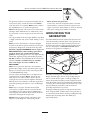
6500EXL
Portable Generator Owner’s Manual
ms? ?
e
l
b
Pro stionsur unit
Que ing yo ore,
tak the st tor
a
ore
Bef ack to gener
b
e
a
h
8
t
e t
call helplin –140
0
27
00– 8–5 CT
8
–
1
M–F
Model No. 9798-2 (6,500 Watt AC Generator) Manual No. B2649 Revision 3 (06/01/2001)
Visit our Generac website: www.generac-portables.com
This is the safety alert symbol. It is used to alert you to potential personal injury hazards.
Obey all safety messages that follow this symbol to avoid possible injury or death.
Generac Portable Products 6500EXL Extended Life Generator
EQUIPMENT
DESCRIPTION
SAFETY RULES
This generator set was designed and manufactured for
specific applications. Do Not attempt to modify the unit or
use it for any application it was not designed for. If you have
any questions about your generator’s application, ask your
dealer or consult the factory.
This generator is an engine–driven, revolving field,
alternating current (AC) generator. It was designed to
supply electrical power for operating compatible electrical
lighting, appliance, tools and motor loads.This manual
contains information for a generator that operates
120 and/or 240 Volt, single phase, 60 Hz devices that
require up to 6,500 watts (6.5 kW) of power that pull up
to 54.2 Amps at 120 Volts or 27.1 Amps at 240 Volts.
The manufacturer could not possibly anticipate every
circumstance that might involve a hazard. For that reason
warnings in the manual and warnings on tags or decals
affixed to the unit are not all–inclusive. If you intend to
handle, operate or service the unit by a procedure or
method not specifically recommended by the manufacturer,
first make sure that such a procedure or method will not
render this equipment unsafe or pose a threat to you and
others.
CAUTION! Do Not exceed the generator’s
wattage/amperage capacity.The total load should not be
greater than 6,500 watts. See “Don’t Overload the
Generator” on page 11.
Read this manual carefully and become familiar
with your generator set. Know its applications, its
limitations and any hazards involved.
The generator’s revolving field is driven at about 3,600 rpm
by a single-cylinder engine.
Every effort has been made to ensure that information in
this manual is accurate and current. However, Generac
reserves the right to change, alter or otherwise improve the
product and this document at any time without prior
notice.
WARNING:
The engine exhaust from this product contains
chemicals known to the State of California to
cause cancer, birth defects, or other reproductive
harm.
CAUTION! Do Not tamper with engine
governed speed. High operating speeds are
dangerous and increase risk of personal injury or
damage to equipment.The generator supplies
correct rated frequency and voltage only when
running at proper governed speed. Incorrect
frequency and/or voltage can damage some
connected electrical loads. Operating at excessively
low speeds imposes a heavy load.When adequate
engine power is not available engine life may be
shortened.
DANGER! You must isolate the generator from
the electric utility using approved transfer
equipment if this unit is used for backup power.
Failure to isolate the generator from the
power utility may result in injury or death to
electric utility workers and damage to the
generator due to a backfeed of electrical energy.
Whenever unit is providing backup power, the
electric utility must be notified.
DANGER! Generator exhaust gases contain
DEADLY carbon monoxide gas. If breathed in
sufficient concentrations, carbon monoxide
can cause unconsciousness or death. Operate
this equipment outdoors where adequate ventilation
is available.
The Emission Control System for this generator is
warranted for standards set by the Environmental
Protection Agency. For warranty information refer to the
engine owner’s manual.
2
Generac Portable Products 6500EXL Extended Life Generator
• The generator produces a very powerful voltage that can
cause serious injury or death by electrocution. Never
touch bare wires or receptacles. Never permit a child or
any unqualified person to operate the generator.
• Never operate the generator:
in rain; in any enclosed compartment; when connected
electrical devices overheat; if electrical output is lost; if
engine or generator sparks; if flame or smoke is observed
while unit is running; if unit vibrates excessively.
• Never handle any kind of electrical cord or device while
standing in water, while barefoot or while hands or feet
are wet. Death or serious injury from electrocution may
result.
GROUNDING THE
GENERATOR
• Use a ground fault circuit interrupter (GFCI) in any damp
or highly conductive area (such as metal decking or steel
work).
The National Electrical Code requires that the frame and
external electrically conductive parts of this generator be
properly connected to an approved earth ground. Local
electrical codes may also require proper grounding of the
unit. For that purpose, a GROUNDING WING NUT is
provided on the generator end (Figure 1).
• Never use worn, bare, frayed or otherwise damaged
electrical cords with the generator. Death, serious injury
and property damage from electrical shock may result.
• Gasoline is highly FLAMMABLE and its vapors are
EXPLOSIVE. Never allow smoking, open flames,
sparks or heat in the vicinity while handling
gasoline. Avoid spilling gasoline on a hot engine. Comply
with all laws regulating storage and handling of gasoline.
• Do Not overfill the fuel tank. Always allow room for fuel
expansion. If tank is overfilled, fuel can overflow
onto a hot engine and cause a FIRE or an
EXPLOSION.
• Never store a generator with fuel in the tank where
gasoline vapors might reach an open flame, spark or pilot
light (as on a furnace, water heater, clothes dryer). FIRE
or an EXPLOSION may result.
• The unit requires an adequate flow of cooling air for its
continued proper operation. Never operate the unit
inside any room or enclosure where the free flow of
cooling air into and out of the unit might be obstructed.
Allow at least 2 feet of clearance on all sides of generator,
even while operating unit outdoors, or you could damage
the unit.
• Never start, or stop the unit with electrical loads
connected to receptacles with the connected devices
turned ON. Start the engine and let it stabilize before
connecting any electrical loads. Disconnect all electrical
loads before shutting down the generator.
• Do Not insert any object through cooling slots of the
engine.You could damage the unit or injure yourself.
Figure 1 — Grounding Wing Nut
Grounding Wing Nut
Generally, connecting a No. 12 AWG (American Wire
Gauge) stranded copper wire to the grounding wing nut
and to an earth–driven copper or brass grounding rod
(electrode) provides adequate protection against electrical
shock. Be careful to keep the grounding wire attached after
connecting the stranded copper wire. However, local codes
may vary widely. Consult with a local electrician for
grounding requirements in your area.
Properly grounding the generator helps prevent electrical
shock if a ground fault condition exists in the generator or
in connected electrical devices. Proper grounding also helps
dissipate static electricity, which often builds up in
ungrounded devices.
3
Generac Portable Products 6500EXL Extended Life Generator
INSTALLING TRAY AND
BATTERY
Your generator requires some assembly and is ready for
use after it has been properly serviced with the
recommended oil and fuel.
If you have any problems with the assembly of your
generator, please call the generator helpline at
1-800-270-1408.
You must purchase and install a 12 Volt DC battery (Series
U1L).The battery should be serviced with electrolyte fluid
and fully charged prior to installation. Install the battery as
follows:
IMPORTANT: Any attempt to run the unit before it has
been serviced with the recommended oil will result in an
engine failure.
• Find the battery tray and fasteners shipped loose in the
carton.
REMOVE GENERATOR
FROM CARTON
• Remove the four battery tray screws from cradle.
• Position the battery tray and install with supplied
hardware (see Figure 2).
Figure 2 — Install Battery Tray
• Set the carton on a rigid flat surface with “This Side Up”
arrows pointing upward.
• Carefully open the top flaps of the shipping carton.
Review “Cold Weather Operation” on page 9.
• Cut down corners at one end of carton from top to
bottom and lay that side of carton down flat.
• Remove all packing material, carton fillers, etc.
• Remove the generator from the shipping carton.
CARTON CONTENTS
Check all contents. If any parts are missing or damaged, call
the generator helpline at 1-800-270-1408.
• The generator
• Set battery onto tray.
• Retain battery to tray with one battery hold down
bracket, two J bolts, two lock washers, two flat washers
and two hex nuts (Figure 3).
• Electric start battery cables
• Generator and engine owner’s manuals
Figure 3 — Secure 12 Volt Battery
• Locking 30 Amp plugs
• Battery charge cables
• Battery tray mounting bracket/hardware
• Spare spark plug and air filter element
• Spark plug wrench
4
Generac Portable Products 6500EXL Extended Life Generator
• Follow the oil grade recommendations and oil fill
instructions given in the engine owner’s manual.
• Connect the red battery cable from the engine starter
switch to positive (+) terminal on the battery
(Figure 4).
NOTE: The generator’s revolving field rides on a
prelubricated and sealed ball bearing that requires no
additional lubrication for the life of the bearing.
Figure 4 — Wire Connections
Add Gasoline
WARNING! Never fill fuel tank indoors. Never
fill fuel tank when engine is running or hot. Do Not
light a cigarette or smoke when filling the fuel tank.
WARNING! Do Not overfill the fuel tank.
Always allow room for fuel expansion.
• Use regular UNLEADED gasoline with the generator
engine. Do Not use premium gasoline. Do Not mix oil
with gasoline.
• Clean area around fuel fill cap, remove cap.
RED wire from
starter switch
• Slowly add unleaded regular gasoline to fuel tank. Be
careful not to overfill. Allow about 1/2" of tank space for
fuel expansion (Figure 5).
BLACK wire
from battery
Figure 5 — Typical Fuel Expansion Space
• Connect the black battery cable to the negative (–)
terminal on the battery (Figure 4).
• Connect the other end of the black cable to the engine,
not the frame (Figure 4).
CAUTION! Be sure the BLACK cable is connected to
the engine mount and not the frame.You could damage the
ground wire.
• Install fuel cap and wipe up any spilled gasoline.
BEFORE STARTING THE
ENGINE
IMPORTANT: It is important to prevent gum deposits from
forming in essential fuel system parts, such as the carburetor,
fuel filter, fuel hose or tank during storage.Also, experience
indicates that alcohol–blended fuels (called gasohol, ethanol
or methanol) can attract moisture, which leads to separation
and formation of acids during storage.Acidic gas can damage
the fuel system of an engine while in storage.
Add Oil
CAUTION! Any attempt to crank or start the engine
before it has been properly filled with the recommended
oil may result in an engine failure.
To avoid engine problems, the fuel system should be
emptied before storage of 30 days or longer. See “Storage”
on page 12. Never use engine or carburetor cleaner
products in the fuel tank or permanent damage may occur.
To fill your engine with oil:
• Place generator on a level surface.
5
Generac Portable Products 6500EXL Extended Life Generator
KNOW YOUR GENERATOR
Read this owner’s manual and safety rules before operating your generator.
Compare the illustrations with your generator, to familiarize yourself with the locations of various controls and
adjustments. Save this manual for future reference.
Fuel Tank
Circuit Breakers (AC)
Recoil Starter
Choke Lever
120 Volt AC, 30 Amp
Receptacle
Run/Stop Switch
120/240 Volt AC,
30 Amp Receptacle
Air Cleaner
12 Volt DC, 10 Amp
Receptacle
Spark Arrester Muffler
120 Volt AC, 20 Amp
Duplex Receptacle
Grounding Wing Nut
Idle Control Switch
12 Volt DC,10 Amp Receptacle — Recharge a
discharged 12 Volt automotive type battery through this
receptacle.
120 Volt AC, 20 Amp, Duplex Receptacle — May be
used to supply electrical power for the operation of
120 Volt AC, 20 Amp, single phase, 60 Hz electrical lighting,
appliance, tool and motor loads.
120 Volt AC, 30 Amp Locking Receptacle — May be
used to supply electrical power for the operation of
120 Volt AC, 30 Amp, single phase, 60 Hz electrical lighting,
appliance, tool and motor loads.
120/240 Volt AC, 30 Amp Locking Receptacle — May
be used to supply electrical power for the operation of
120 and/or 240 Volt AC, 30 Amp, single phase, 60 Hz
electrical lighting, appliance, tool and motor loads.
Air Cleaner — Uses a dry type filter element and foam
pre–cleaner to limit the amount of dirt and dust sucked
into the engine.
Choke Lever — Used when starting a cold engine.
Circuit Breakers (AC) — Each receptacle is provided
with a "push to reset" circuit breaker to protect the
generator against electrical overload.
Fuel Tank — Capacity of seven (7) U.S. gallons.
Grounding Wing Nut — Used for proper grounding of
unit.
Idle Control Switch — With this switch set to ON,
printed circuit board in control panel automatically reduces
engine speed when no load is connected and increases
engine to proper speed when load is applied. However, be
sure switch is OFF when starting engine.
Recoil starter — Used to start the engine.
Run/Stop Switch — Set this switch to "Run" before
using recoil starter. Set switch to "Stop" to switch OFF
engine.
Spark Arrester Muffler — Exhaust muffler lowers
engine noise and is equipped with a spark arrester screen.
6
Generac Portable Products 6500EXL Extended Life Generator
OPERATING THE
GENERATOR
Figure 8 — Choke Lever
CAUTION! Never start or stop the engine with
electrical loads connected to the receptacles AND
with the connected devices turned ON.
Starting the Engine
• Unplug all electrical loads from generator receptacles
before starting the engine.
• Grasp starter grip and pull slowly until you feel slight
resistance, then pull quickly. Do Not let handle “snapback” into recoil housing.
• Make sure the unit is in a level position.
• Open the fuel shut–off valve (Figure 6).
• When engine starts, move choke lever to “Run” position
by sliding it all the way to the right (away from the valve
cover and under the arrow).
Figure 6 — Fuel Shut-off Valve
NOTE: If engine fails to start after 3 pulls, move the choke
lever to “Half” choke position and pull starter rope again
2 times.
NOTE: If the engine still fails to start, review the engine
owner’s manual. Also, check for proper oil level in
crankcase. Unit is equipped with a low oil shutdown
system. See engine owner’s manual for information
regarding the low oil shutdown system.
• Make sure the Idle Control switch is “Off”.
• Place Run/Stop switch in the “Run” position (Figure 7).
Connecting Electrical Loads
Figure 7 — Run/Stop Switch
• Let engine stabilize and warm up for a few minutes after
starting.
• Plug in and turn on the desired 120 and/or 240 Volt AC,
single phase, 60 Hz electrical loads.
• Do Not connect 240 Volt loads to the 120 Volt
receptacles.
• Do Not connect 3–phase loads to the generator.
• Do Not connect 50 Hz loads to the generator.
• DO NOT OVERLOAD THE GENERATOR. Add up
the rated watts (or amps) of all loads to be connected at
one time.This total should not be greater than the rated
wattage/amperage capacity of the generator. See “Don’t
Overload the Generator” on page 11.
• Place the choke lever in the “Full” choke position by
sliding it to the left toward the valve cover in the
direction indicated by the arrow (Figure 8).
7
Generac Portable Products 6500EXL Extended Life Generator
Stopping the Engine
To recharge 12 Volt batteries, proceed as follows:
• Unplug all electrical loads from generator panel
receptacles. Never start or stop engine with electrical
devices plugged in and turned on.
• Check fluid level in all battery cells. If necessary, add
ONLY distilled water to cover separators in battery cells.
Do Not use tap water.
• Put the idle control switch in the “Off” position.
• If the battery is equipped with vent caps, make sure they
are installed and are tight.
• Let engine run at no–load for 30 seconds to stabilize the
internal temperatures of engine and generator.
• If necessary, clean battery terminals.
• Connect battery charge cable connector plug to panel
receptacle identified by the words “12 VOLTS D.C.”
• Move run/stop switch to “Stop”.
• Close the fuel shut–off valve.
• Connect battery charge cable clamp with red handle to
the positive (+) battery terminal (Figure 9).
Operating Automatic Idle Control
Figure 9 — Battery Connections
This switch is designed to greatly improve fuel economy.
When this switch is turned ON, the engine will only
run at its normal high governed engine speed when an
electrical load is connected.When an electrical load is
removed, the engine will run at a reduced speed. With the
switch off, the engine will run at the normal high engine
speed. Always have the switch off when starting and
stopping the engine.
Charging a Battery
WARNING! Storage batteries give off explosive
hydrogen gas while recharging. An explosive mixture
will remain around the battery for a long time after
it has been charged.The slightest spark can ignite
the hydrogen and cause an explosion, resulting in
blindness or other serious injury.
• Connect battery charge cable clamp with black handle
to the negative (–) battery terminal (Figure 9).
WARNING! Do Not permit smoking, open
flame, sparks or any other source of heat around a
battery.Wear protective goggles, rubber apron and
rubber gloves when working around a battery.
Battery electrolyte fluid is an extremely caustic
sulfuric acid solution that can cause severe burns. If
spill occurs flush area with clear water immediately.
• Start engine. Let the engine run while battery recharges.
• When battery has charged, shut down engine
NOTE: Use an automotive hydrometer to test battery
state of charge and condition. Follow the hydrometer
manufacturer’s instructions carefully. Generally, a battery is
considered to be at 100% state of charge when specific
gravity of its fluid (as measured by hydrometer) is 1.260 or
higher.
Your generator has the capability of recharging a discharged
12 Volt automotive or utility style storage battery. Do Not
use the unit to charge any 6 Volt batteries. Do Not use the
unit to crank an engine having a discharged battery.
8
Generac Portable Products 6500EXL Extended Life Generator
COLD WEATHER
OPERATION
CAUTION! Never run unit indoors. Do Not
enclose generator any more than shown.
RECEPTACLES
Under certain weather conditions (temperatures below
40°F [4°C] and a high dew point), your generator may
experience icing of the carburetor and/or the crankcase
breather system.
120/240 Volt AC, 30 Amp, Locking
Receptacle
In an emergency, use the original shipping box as a
temporary shelter:
Use a NEMA L14–30 plug with this receptacle. Connect a
4–wire cord set rated for 250 Volt AC loads at 30 Amps (or
greater) (Figure 11).You can use the same 4–wire cord if
you plan to run a 120 Volt load.
• Cut off all flaps.
• Cut out one of the long sides of the box to expose
exhaust side of unit. Ensure a minimum of two feet
clearance between open side of box and nearest object.
Figure 11 — 120/240 Volt AC, 30 Amp, Locking Receptacle
• Cut appropriate slots to access receptacles of unit.
• Start unit, then place box over it.
IMPORTANT: Remove shelter when temperature is
above 40°F [4°C].
For a more permanent shelter, build a structure that will
enclose three sides and the top of the generator:
• Make sure entire muffler-side of generator is exposed.
Note that your generator may appear different from that
shown in Figure 10.
Figure 10 — Temporary Cold Weather Shelter
Wind
This receptacle powers 120/240 Volt AC, 60 Hz, single
phase loads requiring up to 3,600 watts of power at
30 Amps for 120 Volts; 6,500 watts of power (6.5 kW) at
30 Amps for 240 Volts.The outlet is protected by a 30 Amp
push–to–reset circuit breaker.
CAUTION! Although this outlet states it has a
240 Volt 30 Amp rating (up to 7,200 watts), the
generator is only rated for 6,500 watts. Powering
loads that exceed the wattage/amperage capacity of
the generator can damage it or cause serious
injuries.
120 Volt AC, 30 Amp Locking
Receptacle
• Ensure a minimum of two feet clearance between open
side of box and nearest object.
Use a NEMA L5–30 plug with this receptacle. Connect a
3–wire cord set rated for 125 Volt AC loads at 30 Amps to
the plug (Figure 12).
• Face exposed end away from wind and elements.
• Enclosure should hold enough heat created by the
generator to prevent problems.
9
Generac Portable Products 6500EXL Extended Life Generator
Figure 12 — 120 Volt AC, 30 Amp, Locking Receptacle
Figure 13 — 120 Volt AC, 20 Amp, Duplex Receptacle
12 Volt DC, 10 Amp Receptacle
This receptacle allows you to recharge a 12 Volt
automotive or utility style storage battery with the battery
charge cables provided (Figure 14).This receptacle can not
recharge 6 Volt batteries and can not be used to crank an
engine having a discharged battery. See the section
“Charging a Battery” (page 8) before attempting to
recharge a battery.
Use this receptacle to operate 120 Volt AC, 60 Hz, single
phase loads requiring up to 3,600 watts (3.6 kW) of power
at 30 Amps.The outlet is protected by a 30 Amp
push–to–reset circuit breaker.
120 Volt AC, 20 Amp, Duplex
Receptacle
Figure 14 — 12 Volt DC, 10 Amp Receptacle
Each receptacle (Figure 13) is protected against overload by
a 20 Amp push–to–reset circuit breaker.
Use each receptacle to operate 120 Volt AC, single–phase,
60 Hz electrical loads requiring up to 2,400 watts (2.4 kW)
at 20 Amps of current. Use cord sets that are rated for
125 Volt AC loads at 20 Amps (or greater).
10
Generac Portable Products 6500EXL Extended Life Generator
DON’T OVERLOAD THE
GENERATOR
• The rated wattage of lights can be taken from wattage
listed on the light bulbs.The rated wattage of tools,
appliances and motors can usually be found on a data
plate or decal affixed to the device. Use Figure 15 below
as a general reference.
Overloading a generator in excess of its rated wattage
capacity can result in damage to the generator and/or
connected electrical devices. Observe the following, to
prevent overloading the unit:
• Some electric motors, such as induction types, require
about three times more watts of power for starting than
for running.This surge of power lasts for only a few
seconds when starting such motors. Be sure you allow
for this high starting wattage when selecting electrical
devices to connect to your generator. First figure the
watts needed to start the largest motor. Add to that
figure the running watts of all other connected loads.
• Add up the total wattage of all electrical devices to be
connected at one time.This total should NOT be greater
than the generator’s wattage capacity.
• If the appliance, tool or motor does not give wattage,
multiply 120 Volts times ampere rating to determine
watts (volts x amps = watts).
Figure 15 — Wattage Reference Guide
Recreational/Home Uses
Tool/Appliance....................................................Watts
AM/FM clock radio ....................................................................50
Light bulb....................................................................................100
Fan................................................................................................200
20" color TV ..............................................................................400
*Deep freezer ...........................................................................500
Personal computer and 15" monitor...................................800
*1/3 hp furnace fan blower ....................................................800
Microwave oven........................................................................800
*18 cu ft refrigerator...............................................................800
Sump pump..............................................................................1000
Electric skillet..........................................................................1250
*½ hp water well pump .......................................................1400
*12,000 Btu window air conditioner ................................1400
Space heater............................................................................1800
Electric water heater ............................................................4000
Professional/Contractor Uses
Tool/Appliance....................................................Watts
*1/3 hp airless sprayer ............................................................600
3/8" hammer drill .....................................................................600
Variable speed Sawzall® .........................................................960
½" power drill ........................................................................1000
Quartz-halogen work light ..................................................1000
Belt sander...............................................................................1200
7 ¼" circular saw ...................................................................1500
7 ¼" worm drive saw ...........................................................1600
*1½ hp air compressor ........................................................1800
*10" power miter saw...........................................................1800
6" bench grinder.....................................................................1800
*6" table planer.......................................................................1800
*10" table/radial arm saw .....................................................2000
Wire feed welder...................................................................2400
* allow 3 times listed watts for starting this device
11
Generac Portable Products 6500EXL Extended Life Generator
SPECIFICATIONS
the rotor and stator winding insulation.Water and dirt
buildup on the generator internal windings will eventually
decrease the insulation resistance of these windings.
Maximum Surge Watts . . . . . . . . . . . . . . . . .8,125 watts
Continuous Wattage Capacity . . . . . . . . . . .6,500 watts
Power Factor . . . . . . . . . . . . . . . . . . . . . . . . . . . . . .1.0
Rated Maximum Continuous AC Load Current:
At 120 Volts . . . . . . . . . . . . . . . . . . . . . . .54.2 Amps
At 240 Volts . . . . . . . . . . . . . . . . . . . . . . .27.1 Amps
Phase . . . . . . . . . . . . . . . . . . . . . . . . . . . . . . . . .1–phase
Rated Frequency . . . . . . . . . . . . . . . . . . . . . . .60 Hertz
Fuel Tank Capacity . . . . . . . . . . . . . . . . . . . 7 U.S. gallons
Shipping Weight . . . . . . . . . . . . . . . . . . . . . . . . .200 lbs.
To Clean the Generator
• Use a damp cloth to wipe exterior surfaces clean.
• A soft bristle brush may be used to loosen caked on dirt
or oil.
• A vacuum cleaner may be used to pick up loose dirt and
debris.
• Low pressure air (not to exceed 25 psi) may be used to
blow away dirt. Inspect cooling air slots and opening on
generator.These openings must be kept clean and
unobstructed.
GENERAL MAINTENANCE
RECOMMENDATIONS
STORAGE
The Owner/Operator is responsible for making sure that
all periodic maintenance tasks are completed on a timely
basis; that all discrepancies are corrected; and that the unit
is kept clean and properly stored. Never operate a
damaged or defective generator.
The generator should be started at least once every seven
days and allowed to run at least 30 minutes. If this cannot
be done and you must store the unit for more than
30 days, use the following guidelines to prepare it for
storage.
Engine Maintenance
Generator Storage
See engine owner’s manual for instructions.
• Clean the generator as outlined in “To Clean the
Generator.”
CAUTION! Avoid prolonged or repeated skin
contact with used motor oil. Used motor oil has
been shown to cause skin cancer in certain
laboratory animals.Thoroughly wash exposed areas
with soap and water.
KEEP OUT OF REACH OF CHILDREN. DON'T
POLLUTE. CONSERVE RESOURCES. RETURN
USED OIL TO COLLECTION CENTERS.
• Check that cooling air slots and openings on generator
are open and unobstructed.
CAUTION! Storage covers can be flammable. Do
Not place a storage cover over a hot generator. Let
the unit cool for a sufficient time before placing the
cover on the unit.
Generator Maintenance
Generator maintenance consists of keeping the unit clean
and dry. Operate and store the unit in a clean dry
environment where it will not be exposed to excessive
dust, dirt, moisture or any corrosive vapors. Cooling air
slots in the generator must not become clogged with snow,
leaves or any other foreign material.
Engine Storage
NOTE: Do Not use a garden hose to clean generator.
Water can enter engine fuel system and cause problems. In
addition, if water enters generator through cooling air slots,
some of the water will be retained in voids and cracks of
• Replace gasoline can if it starts to rust. Rust and/or dirt
in gasoline can cause problems when that fuel is used
with this unit.
See engine owner’s manual for instructions.
Other Storage Tips
• Do Not store gasoline from one season to another.
• Store in clean and dry area.
12
Generac Portable Products 6500EXL Extended Life Generator
TROUBLESHOOTING
Problem
Engine is running, but no
AC output is available.
Engine runs good at noload but “bogs” down"
when loads are connected.
Cause
Correction
1.
2.
3.
4.
One of the circuit breakers is open.
Fault in generator.
Poor connection or defective cord set.
Connected device is bad.
1.
2.
3.
4.
1.
2.
3.
Short circuit in a connected load.
Engine speed is too slow.
Generator is overloaded.
1.
2.
3.
4.
1.
2.
3.
4.
5.
Engine will not start; or
starts and runs rough.
Engine shuts down during
operation.
Shorted generator circuit.
Run/Stop Switch set to “STOP”.
Dirty air cleaner.
Out of gasoline.
Stale gasoline.
Spark plug wire not connected to
spark plug.
6. Bad spark plug.
7. Water in gasoline.
8. Overchoking.
9. Excessively rich fuel mixture.
10. Intake valve stuck open or closed.
11. Engine has lost compression.
12. Failed battery.
1. Out of gasoline.
2. Low oil level.
1. Load is too high.
4.
1.
2.
3.
4.
5.
2.
1.
Dirty air filter.
Choke is opened too soon.
2.
1.
2.
Carburetor is running too rich or too
lean.
2.
6.
7.
8.
9.
10.
11.
12.
1.
2.
1.
Engine lacks power.
Engine “hunts” or falters.
13
Reset circuit breaker.
Contact Generac service facility.
Check and repair.
Connect another device that is in
good condition.
Disconnect shorted electrical load.
Contact Generac service facility.
See “Don't Overload the Generator”
on page 11.
Contact Generac service facility.
Set switch to “RUN”.
Clean or replace air cleaner.
Fill fuel tank.
Drain gas tank; fill with fresh fuel.
Connect wire to spark plug.
Replace spark plug.
Drain gas tank; fill with fresh fuel.
Open choke fully and crank engine.
Contact Generac service facility.
Contact Generac service facility.
Contact Generac service facility.
Replace battery.
Fill fuel tank.
Fill crankcase to proper level.
See “Don't Overload the Generator”
on page 11.
Replace air filter.
Move choke to halfway position until
engine runs smoothly.
Contact Generac service facility.
Generac Portable Products 6500EXL Extended Life Generator
SCHEMATIC
14
Generac Portable Products 6500EXL Extended Life Generator
WIRING DIAGRAM
15
Generac Portable Products 6500EXL Extended Life Generator
EXPLODED VIEW – MAIN UNIT
16
Generac Portable Products 6500EXL Extended Life Generator
PARTS LIST – MAIN UNIT
Item
1
2
3
4
5
6
7
8
9
10
11
12
13
14
15
16
Part #
A92432
A92531
A92731
92247
92679G
94981G
65791
67451
22129
86307
25254
92609
82857
92532
90239
66476
Qty
1
1
1
1
1
1
1
1
2
4
1
2
4
1
1
2
17
18
19
20
24
25
26
27
28
29
30
31
32
33
34
35
36
37
38
39
40
41
42
43
44
A7433
40976
83083
81917
B4986
66825C
74908
86308B
65795
66849C
67022
84132
66386
66849
B4871
22769
86494
86292
77395
83465
78831B
80270
78299
B4363
B1998
1
2
1
1
1
1
4
4
2
1
1
1
1
2
1
1
1
9
4
4
4
1
1
1
1
45
B92039
1
Description
CRADLE
SUPPORT, Engine
SUPPORT, Engine & Muffler
HOUSING, Engine Adapter
ASSEMBLY, Rotor (Incls Item 7)
ASSEMBLY, Stator
BEARING
WASHER, M8 Flat
WASHER, M8 Lock
SCREW, 5/16-24 x 3/4 SEMS
SCREW, 5/16-24 x 9-7/8"
MOUNT,Vibration
MOUNT,Vibration
BRACKET, Muffler
GASKET, Exhaust
SCREW, M6-1 x 12 with Lock
Washer
MUFFLER
SCREW, M8 - 1.25 x 20
SCREEN, Spark Arrest
PIN, 4mm x 10 Roll
DECAL, Ground
CARRIER, Rear Bearing
TAPTITE, M5-0.8 x 10
BOLT, M6-1 x 165mm Stator
RECTIFIER, Battery Charge
TAPTITE, M5-0.8 x 30
GROMMET, Rubber
ASSEMBLY, Power Regulator
ASSEMBLY, Brush Holder
TAPTITE, M5-0.8 x 16
COVER, Bearing Carrier
WASHER, #10 Int. Shakeproof
SCREW, M6-1.0 x 16 Wing
SCREW, #10 Self Drilling
NUT, M6 Flange Lock
GROMMET,Tank
HHCS, M6-1.0 x 60, SEMS
VALVE,Tank
BUSHING, Plastic Tank
CAP, Fuel Gauge
TANK, Fuel 7 Gal Assy.
(Includes 41 & 42)
SHIELD, Heat
Item
46
47
48
49
51
52
55
57
58
59
60
61
62
63
64
65
66
67
68
69
Part #
Qty Description
92665
1
INSULATION, #2-1/4"
85000
1
CLIP, Insulation
14353621 1
WIRE, Ground
26850
2
WASHER, M6 Shakeproof
92982
1
DECAL, Danger
96059
2
DECAL, Heat Shield
189160
12 NUT, 5/16-18 Serrated Flange
96060
1
DECAL, Control Panel
92630
1
ASSEMBLY, Control Box
NSP
1
ENGINE
22531
2
SCREW, 5/16-18 x 1-3/4"
22142
2
SCREW, 5//16 - 18 x 3/4"
93826
1
DECAL, Start Instructions
77282
1
SWITCH, Starter
22287
2
SCREW, 1/4 - 20" x 3/4"
22097
2
WASHER, M6 Lock
22127
2
NUT, 1/4 - 20" Hex
78289
1
BRACKET, Starter Switch
B96068
1
SHIELD, Heat
56893
5
CRIMPTITE, 10 - 24 x 1/2
Items Not Illustrated:
B2649
1
Generator Owner’s Manual
A8927
1
Engine Owner’s Manual
37806
1
125V 30A Locking plug
43438
1
240V 30A Locking plug
72347
1
Spark plug
73111
1
Air cleaner element
84882
1
Spark plug wrench
65787
1
Battery charge cable
Battery Tray Components:
22129
2
Lockwasher, M8
45771
2
Hex nut M8
96925
1
Battery tiedown
96924
2
J-bolt
15453621 1
Battery cable, positive
15553621 1
Battery cable, negative
96923
1
Battery tray
22145
2
Flat washer
58443
4
Screws, battery tray
Optional Accessories Not Included:
84883
Cord Wrap
17
Generac Portable Products 6500EXL Extended Life Generator
EXPLODED VIEW AND PARTS LIST – CONTROL PANEL
Item
1
2
3
4
5
6
7
8
9
10
11
12
13
Part #
A92070
23897
49226
91526
82538
82881
43181
43182
90418
75207A
75207
23365
68868
Qty
1
4
4
4
1
4
4
4
1
2
2
6
1
Description
PANEL, Control
FLAT WASHER, #10 M5
LOCK WASHER, M5
SCREW, M5-0.8 x 12mm
SWITCH, Idle Control
LOCK WASHER, 7/16"
SCREW, M3 - 0.5 x 10mm
LOCK WASHER, M3
OUTLET, 12V
CIRCUIT BREAKER, 30A
CIRCUIT BREAKER, 20A
WASHER, #8 Shakeproof
OUTLET, 120 Volt, 30A Locking
18
Item
14
Part #
43437
15
16
17
18
19
20
21
22
23
24
25
26
68759
43180
22264
51715
64526
83970
64525
87962
84335
84134
B92069
84028
Qty Description
1
OUTLET, 120V/240V, 30A
Locking
1
OUTLET, 120V, 20A Duplex
6
FLAT WASHER, M4
6
LOCK WASHER, #8 M4
6
NUT, M4-0.7 Hex
8
SCREW, #6-32 x 3/8"
1
BOARD, System Control
4
STAND-OFF, 3/4" Hex
1
CIRCUIT BREAKER, 12V, 10A
1
ASSEMBLY,Wire Harness
1
GROMMET, Rubber Conn.
1
BOX, Control Panel
1
TRANSFORMER, Idle Control
Generac Portable Products 6500EXL Extended Life Generator
NOTES
19
PORTABLE GENERATOR LIMITED WARRANTY
GENERAC PORTABLE PRODUCTS (hereafter referred to as the COMPANY) warrants to the original purchaser that the
components in its portable generator will be free from defects in materials or workmanship for the items and period set
forth below from the date of original purchase.This warranty does not include the gasoline engine when furnished or
attached because such engine is covered solely by the engine manufacturer’s warranty. Starting batteries are not warranted
by the COMPANY.The term “original purchaser” means the person for whom the generator is originally purchased.This
warranty is not transferable and applies only to portable generators driven by an overhead valve engine.
Warranty Schedule:
Consumer*
Warranted solely by the engine manufacturer
Commercial*
Engine
All other parts
2 years (2nd year parts only)
1 Year
With the exception of European Community Countries, all units bound for export shall be warranted for One (1)
Year in Consumer applications, and 90 days in Commercial applications as defined below.
*NOTE: For the purpose of this warranty "consumer use" means personal residential household use by
original purchaser.This warranty does not apply to units used for Prime Power in place of utility.
"Commercial Use" means all other uses, including rental, construction, commercial and income producing
purposes. Once a generator has experienced commercial use, it shall thereafter be considered a
commercial use generator for the purposes of this warranty.
During said warranty period, the COMPANY will, at is option, repair or replace any part which, upon examination by the
COMPANY, is found to be defective under normal use and service**. All transportation costs under warranty, including
return to the factory if necessary, are to be borne by the purchaser and prepaid by the purchaser.This warranty does not
cover normal maintenance and service and does not apply to a generator set, alternator, or parts which have been
subjected to improper or unauthorized installation or alteration, misuse, negligence, accident, overloading, overspeeding,
improper maintenance, repair or storage so as, in the COMPANY’s judgement, to adversely affect its performance and
reliability.
**NORMAL WEAR: As with all mechanical devices, the generator needs periodic parts service and
replacement to perform well.This warranty will not cover repair when normal use has exhausted the life of
a part or generator.
THERE IS NO OTHER EXPRESS WARRANTY.THE COMPANY HEREBY DISCLAIMS ANY AND ALL
IMPLIED WARRANTIES, INCLUDING BUT NOT LIMITED TO THOSE OF MERCHANTABILITY AND
FITNESS FOR A PARTICULAR PURPOSE TO THE EXTENT PERMITTED BY LAW.THE DURATION OF
ANY IMPLIED WARRANTIES WHICH CANNOT BE DISCLAIMED IS LIMITED TO THE TIME PERIOD AS
SPECIFIED IN THE EXPRESS WARRANTY. LIABILITY FOR CONSEQUENTIAL, INCIDENTAL OR SPECIAL
DAMAGES UNDER ANY AND ALL WARRANTIES IS EXCLUDED. THE COMPANY ALSO DISCLAIMS ANY
RESPONSIBILITY FOR INCIDENTAL OR CONSEQUENTIAL DAMAGES, SUCH AS THE LOSS OF TIME OR
THE USE OF THE POWER EQUIPMENT, OR ANY COMMERCIAL LOSS DUE TO THE FAILURE OF THE
EQUIPMENT:AND ANY IMPLIED WARRANTIES ARE LIMITED TO THE DURATION OF THIS WRITTEN
WARRANTY.
Some states do not allow limitations on how long an implied warranty lasts, or the exclusion or limitation of incidental or
consequential damages, so the above limitations or exclusions may not apply to you.This warranty gives you specific legal
rights and you may also have other rights, which vary from state to state.
For service, see your nearest COMPANY authorized warranty service facility or call 1-877-544-0982. Or look on the
internet at www.generac-portables.com.Warranty service can be performed only by a COMPANY authorized service
facility.This warranty will not apply to service at any other facility. At the time of requesting warranty service, evidence of
original purchase date must be presented.
GENERAC PORTABLE PRODUCTS
Jefferson,Wisconsin U.S.A.