1
INSTALLATION GUIDE
Alarm Control Panel
CA10 plus
(Program Version 4.7)
®
GDAŃSK
ca10pi_e 11/03
WARNINGS
Due to safety reasons, alarm system should be installed by qualified personnel only.
Telephone terminals of the panel should be connected to PSTN lines only.
Connecting to ISDN lines may lead to damage of the equipment.
Because alarm system may contain hazardous items, its components should be kept
out of reach of unqualified personnel.
In order to avoid the risk of electric shock, read carefully this manual before
proceeding to installation. Any connections should be made in deenergized state
only (i.e. with power supply disconnected).
In the event of service operations consisting in fuse replacement, they must only be
carried out after disconnecting the supply voltage. For the replacement, use only the
fuses which have identical parameters as the original ones.
It is recommended that the manufacturer’s required housings and power supply units
be used .
Making any construction changes or unauthorized repairs is prohibited. This applies,
in particular, to modification of assemblies and components.
CAUTION !
It is impermissible to connect a fully discharged battery (voltage on terminals without
a load less than 11V) to the alarm panel. To avoid hardware damage, fully
discharged or never used battery should be precharged using proper charger.
The batteries used in the alarm systems contain lead. The old batteries must not be
thrown away, but disposed of as required by the existing regulations (European
Directives 91/157/EEC and 83/86/EEC).
CERTIFICATE of CONFORMITY
Manufactured by:
Equipment type:
SATEL sp. z o.o.
Control panel CA-10
POLAND
Complies with Directives of the Council of the European Union:
Low Voltage Directives
73/23/EEC revised by 93/68/EEC
EMC Directive
89/336/EEC revised by 91/263/EEC, 92/31/EEC, 93/68/EEC
R&TTE Directive
1999/5/EC (network connection, TBR21)
GDAŃSK,
date: 2003-11-03
Head of Test Laboratory: Stanisław Galla
NOTE!
The control panels with internal pulse power supply require a different approach (as compared with the
previously manufactured CA-10v3.x panels) during the power-up procedure. Refer to the section on
connecting power supply and starting the control panel.
History of the manual updates – see the end of this manual.
CONTENTS
GENERAL DESCRIPTION OF THE CONTROL PANEL ............................................................................5
TECHNICAL DESCRIPTION OF THE CONTROL PANEL........................................................................6
ZONES ................................................................................................................................................................6
OUTPUTS............................................................................................................................................................8
KEYPADS .........................................................................................................................................................11
LCD Keypad...............................................................................................................................................11
LED Keypad ...............................................................................................................................................12
ACCESS CODES AND AUTHORITY LEVELS ........................................................................................................12
PARTITIONS ......................................................................................................................................................13
MONITORING....................................................................................................................................................14
DIALER ............................................................................................................................................................15
REMOTE PROGRAMMING – DOWNLOADING ...............................................................................................16
INSTALLATION OF THE CONTROL PANEL............................................................................................17
DESCRIPTION OF CONTROL PANEL MAIN BOARD .............................................................................................17
CONNECTION OF KEYPADS...............................................................................................................................20
CONNECTION OF ZONE EXPANDER ...................................................................................................................22
CONNECTION OF DETECTORS ...........................................................................................................................23
CONNECTION OF SIGNALING DEVICES ..............................................................................................................24
CONNECTIONS OF TELEPHONE LINE .................................................................................................................25
CONNECTION OF VOICE SYNTHESIZER .............................................................................................................26
CONNECTION OF PRINTER OR COMPUTER ........................................................................................................26
CONNECTION OF POWER SUPPLY .....................................................................................................................27
Description of electrical connections to the CA-10 OBU housing.............................................................27
Control panel power-up starting procedure...............................................................................................27
STARTING THE CONTROL PANEL ......................................................................................................................28
ACTIVATING SELECTED FUNCTIONS .....................................................................................................29
TELEPHONE MESSAGING - ALARM REPORTING..................................................................................................30
REPORTING TO TELEPHONE MONITORING STATION .........................................................................................30
DOWNLOADING - TELEPHONE COMMUNICATION WITH THE COMPUTER ...........................................................32
Modem initialization ..................................................................................................................................33
GUARD CONTROL FUNCTION ...........................................................................................................................34
PROGRAMMING - SERVICE FUNCTIONS................................................................................................34
SERVICE MODE ................................................................................................................................................35
PROGRAMMING WITH THE LED KEYPAD .........................................................................................................35
BIT Functions.............................................................................................................................................35
DEC Functions...........................................................................................................................................35
HEX Functions ...........................................................................................................................................36
PROGRAMMING WITH THE LCD KEYPAD .........................................................................................................36
SERVICE FUNCTIONS OF THE LCD KEYPAD .....................................................................................................37
Bit Functions ..............................................................................................................................................37
Bit Functions with a List ............................................................................................................................37
Multiparameter Functions..........................................................................................................................37
Editing Text ................................................................................................................................................37
CONTROL PANEL SERVICE FUNCTIONS ................................................................................................38
FS-0 - exiting service mode........................................................................................................................38
FUNCTIONS PROGRAMMING BASIC PARAMETERS .............................................................................................38
FS-1 - changing service code .....................................................................................................................38
FS-2 - programming control panel identifier (HEX)..................................................................................38
FS-3 - programming computer identifier (HEX)........................................................................................38
FS-4 - programming computer telephone number (HEX)..........................................................................39
FS-5 - programming the system options (BIT) ...........................................................................................40
FS-6 - programming entry delay, exit delay , and alarm time (DEC)........................................................42
FS-7 - programming the counting line counters (DEC).............................................................................42
FUNCTIONS PROGRAMMING ASSIGNMENT ........................................................................................................42
FS-8 - programming partition 1 zones (BIT) .............................................................................................42
FS-9 - programming partition 2 zones (BIT) .............................................................................................42
FS-10 - programming partition 3 zones (BIT) ...........................................................................................42
FS-11 - programming partition 4 zones (BIT) ...........................................................................................43
FS-12 - programming zones displayed in partition 1 keypad (BIT)...........................................................43
CONTENTS
FS-13 - programming zones displayed in partition 2 keypad (BIT) ...........................................................43
FS-14 - programming zones displayed in partition 3 keypad (BIT) ...........................................................43
FS-15 - programming zones displayed in partition 4 keypad (BIT) ...........................................................43
FS-16 - programming bypassed zones in partition 1 (BIT) ........................................................................43
FS-17 - programming bypassed zones in partition 2 (BIT) ........................................................................43
FS-18 - programming bypassed zones in partition 3 (BIT) ........................................................................43
FS-19 - programming bypassed zones in partition 4 (BIT) ........................................................................43
FS-20 - programming partition 1 options (BIT).........................................................................................43
FS-21 - programming partition 2 options (BIT).........................................................................................45
FS-22 - programming partition 3 options (BIT).........................................................................................45
FS-23 - programming partition 4 options (BIT).........................................................................................45
FUNCTIONS PROGRAMMING ZONE PARAMETERS .............................................................................................45
FS-24 - programming zone sensitivity........................................................................................................45
FS-25 - programming detector type (DEC)................................................................................................46
FS-26 - programming zone reaction type (DEC) .......................................................................................47
FS-27 - programming zone options (BIT) ..................................................................................................48
FS-28 - programming individual entry delay (DEC)..................................................................................48
FS-29 - programming maximum zone violation times................................................................................49
FS-30 - programming the zone no violation time.......................................................................................49
FUNCTIONS PROGRAMMING OUTPUT PARAMETERS .........................................................................................50
FS-31 - programming OUT1 output...........................................................................................................50
FS-32 - programming list of zones OUT1 (BIT).........................................................................................52
FS-33 - programming OUT2 output...........................................................................................................52
FS-34 - programming list of zones OUT2 (BIT).........................................................................................52
FS-35 - programming OUT3 output...........................................................................................................52
FS-36 - programming list of zones OUT3 (BIT).........................................................................................52
FS-37 - programming OUT4 output...........................................................................................................52
FS-38 - programming list of zones OUT4 (BIT).........................................................................................53
FS-39 - programming OUT5 output...........................................................................................................53
FS-40 - programming list of zones OUT5 (BIT).........................................................................................53
FS-41 - programming OUT6 output...........................................................................................................53
FS-42 - programming list of zones OUT6 (BIT).........................................................................................53
FUNCTIONS PROGRAMMING PARAMETERS OF TRANSMISSION TO MONITORING STATIONS .................................53
FS-43 - programming station 1 number 1 (HEX).......................................................................................53
FS-44 - programming station 2 number (HEX)..........................................................................................53
FS-45 - programming station 1 format (HEX) ...........................................................................................53
FS-46 - programming station 2 format (HEX) ...........................................................................................53
FS-47 - programming monitoring options (BIT) ........................................................................................54
FUNCTIONS PROGRAMMING IDENTIFIERS .........................................................................................................55
FS-48 - programming zone events identifier for station 1 (HEX) ..............................................................55
FS-49 - programming partition 1 events identifier for station 1 (HEX).....................................................55
FS-50 - programming partition 2 events identifier for station 1 (HEX).....................................................55
FS-51 - programming partition 3 events identifier for station 1 (HEX).....................................................55
FS-52 - programming partition 4 events identifier for station 1 (HEX).....................................................55
FS-53 - programming system events identifier for station 1 (HEX) ...........................................................55
FS-54 - programming zone events identifier for station 2 (HEX) ..............................................................55
FS-55 - programming partition 1 events identifier for station 2 (HEX).....................................................55
FS-56 - programming partition 2 events identifier for station 2 (HEX).....................................................55
FS-57 - programming partition 3 events identifier for station 2 (HEX).....................................................55
FS-58 - programming partition 4 events identifier for station 2 (HEX).....................................................56
FS-59 - programming system events identifier for station 2 (HEX) ...........................................................56
FUNCTIONS PROGRAMMING ZONE EVENT CODES ............................................................................................56
FS-60 - programming zone alarm codes (HEX).........................................................................................56
FS-61 - programming zone tamper alarm codes (HEX).............................................................................57
FS-62 - programming zone trouble codes (HEX).......................................................................................57
FS-63 - programming zone violation codes (HEX) ....................................................................................57
FS-64 - programming zone RESTORE codes (HEX)..................................................................................57
FS-65 - programming zone TAMPER RESTORE codes (HEX) .................................................................57
FS-66 - programming zone TROUBLE RESTORE codes (HEX) ...............................................................57
FS-67 - programming zone event assignment to station 1 (BIT) ................................................................57
FS-68 - programming zone event assignment to station 2 (BIT) ................................................................57
FUNCTIONS PROGRAMMING PARTITION EVENT CODES ......................................................................................58
FS-69 - programming partition 1 event codes (HEX) ................................................................................58
CONTENTS
FS-70 - programming partition 2 event codes (HEX) ................................................................................58
FS-71 - programming partition 3 event codes (HEX) ................................................................................58
FS-72 - programming partition 4 event codes (HEX) ................................................................................58
FS-73 - programming partition 1 event assignment to station 1 (BIT) ......................................................59
FS-74 - programming partition 2 event assignment to station 1 (BIT) ......................................................59
FS-75 - programming partition 3 event assignment to station 1 (BIT) ......................................................59
FS-76 - programming partition 4 event assignment to station 1 (BIT) ......................................................59
FS-77 - programming partition 1 event assignment to station 2 (BIT) ......................................................59
FS-78 - programming partition 2 event assignment to station 2 (BIT) ......................................................59
FS-79 - programming partition 3 event assignment to station 2 (BIT) ......................................................59
FS-80 - programming partition 4 event assignment to station 2 (BIT) ......................................................59
FUNCTIONS PROGRAMMING SYSTEM EVENT CODES ........................................................................................60
FS-81 - programming system event codes - set I (HEX) ............................................................................60
FS-82 – programming system event codes - set II (HEX) ..........................................................................60
FS-83 - programming system event assignment to station 1 (BIT) ............................................................61
FS-84 - programming system event assignment to station 2 (BIT) ............................................................61
FS-85 - programming test transmission time (DEC)..................................................................................61
FS-86 - programming the „AC loss” report delay (DEC) .........................................................................61
FUNCTIONS PROGRAMMING DIALER ................................................................................................................61
FS-87 - programming telephone number 1 (HEX).....................................................................................61
FS-88 - programming telephone number 2 (HEX).....................................................................................62
FS-89 - programming telephone number 3 (HEX).....................................................................................62
FS-90 - programming telephone number 4 (HEX).....................................................................................62
FS-91 - programming telephone number 5 (HEX).....................................................................................62
FS-92 - programming telephone number 6 (HEX).....................................................................................62
FS-93 - programming telephone number 7 (HEX).....................................................................................62
FS-94 - programming telephone number 8 (HEX).....................................................................................62
FS-95 - programming assignment of partitions and messages (BIT).........................................................62
FS-96 - programming message 1 (POLPAGER format) ............................................................................63
FS-97 - programming message 2 (POLPAGER)........................................................................................63
FS-98 - programming message 3 (POLPAGER)........................................................................................63
FS-99 - programming message 4 (POLPAGER)........................................................................................63
FS-100 - programming number of queues and retries in a queue (DEC) ..................................................63
FS-101 - programming number of rings before answer (DEC) .................................................................64
FUNCTIONS PROGRAMMING TIMERS..............................................................................................................64
FS-102 - programming TIMER 1 (DEC)....................................................................................................64
FS-103 - programming TIMER 2 (DEC)....................................................................................................64
FS-104 - programming TIMER 3 (DEC)....................................................................................................64
FS-105 - programming TIMER 4 (DEC)....................................................................................................64
FS-106 - programming TIMER functions (HEX) .......................................................................................64
SPECIAL FUNCTIONS ........................................................................................................................................65
FS-107 - restoration of default settings......................................................................................................65
FS-108 - clearing event log........................................................................................................................65
FS-109 - programming default identification codes ..................................................................................65
FS-110 - restoring default codes................................................................................................................65
FS-111 - programming keypad addresses (BIT) ........................................................................................66
FS-112 - start of programming through RS-232 ........................................................................................66
FS-113 - event log printout (all events)......................................................................................................67
FS-114 - alarm log printout .......................................................................................................................67
FS-115 - trouble log printout .....................................................................................................................67
FS-116 - partition event printout (arming/disarming) ...............................................................................67
FS-117 - permissible telephone line loss delay (DEC)...............................................................................67
FS-118 - parameters of pager station signals (HEX).................................................................................67
FS-119 - programming message 1 (HEX) ..................................................................................................68
FS-120 - programming message 2 (HEX) ..................................................................................................68
FS-121 - programming message 3 (HEX) ..................................................................................................68
FS-122 - programming message 4 (HEX) ..................................................................................................68
FS-123- counter count-up times.................................................................................................................68
FS-124- keypad address auto-detect ..........................................................................................................68
FS-125- testing outputs ..............................................................................................................................68
ADDITIONAL FUNCTIONS..................................................................................................................................69
FS-126- programming partition control codes (HEX). ..............................................................................69
FS-127- zones bypassed on no exit from partition 1 (BIT).........................................................................69
CONTENTS
FS-128- zones bypassed on no exit from partition 2 (BIT).........................................................................69
FS-129- zones bypassed on no exit from partition 3 (BIT).........................................................................69
FS-130- zones bypassed on no exit from partition 4 (BIT).........................................................................69
FS-131 - programming additional options (BIT) .......................................................................................69
FS-132 - programming clock correction (DEC).........................................................................................71
FS-133 - programming the time of test transmission to the monitoring station (DEC)..............................71
FS-134 - programming codes to bypass the control panel zones ...............................................................72
FS-135 - programming codes to unbypass the control panel zones ...........................................................72
FS-136 – programming of prefix for extension of identifiers in TELIM transmission format....................72
FS-137 - programming codes to be sent to the monitoring station in TELIM transmission format...........72
RESTORING DEFAULT SETTINGS, ERASING CODES ...........................................................................................72
REMOTE PROGRAMMING – DLOAD10 ....................................................................................................73
Program configuration for communication with the panel ........................................................................73
TABLE OF HEX CHARACTERS ...................................................................................................................76
STATES SIGNALED WITH LEDS .................................................................................................................77
STATES SIGNALED WITH SOUND..............................................................................................................78
TECHNICAL DATA .........................................................................................................................................79
HISTORY OF THE MANUAL UPDATES .....................................................................................................82
GENERAL DESCRIPTION OF THE CONTROL PANEL
The CA-10 plus alarm control panel is a new version of the hitherto manufactured
CA-10. The changes, as compared with the previous version, refer mainly to the
design and technical parameters of the panel. Its resistance to surge currents has
been considerably improved, so now it meets by a good margin the requirements of
standards consistent with the European Union EMC 89/336/UE Directive. It is
a state-of-the-art, microprocessor-based alarm control panel, developed in
accordance with the latest trends in the field of burglary and assault signaling.
The alarm control panel incorporates a number of solutions, which were previously
encountered only in special purpose equipment. Some of the solutions are an
absolute novelty.
Basic functional features:
• operating the panel from remote LCD text display keypads or from LED
keypads,
• connection of up to four independent keypads,
•
remote control by means of a telephone set (selected functions) – support of the
MST-1 module,
• possibility of four-partition operation, with completely separate alarm systems, or
common zone partitions or internal partitions,
• 10 to 16 fully programmable zone inputs (8 zones on the main board, 2 on
each keypad, extension through zones of next keypads or expander), each
capable of performing one of 21 functions,
• support of any detectors in NO, NC, EOL and two-parameter (2EOL)
configuration with individual zone violation,
• 6 programmable outputs, each being able to perform any of 41 functions.
• built-in telephone communicator for:
- messaging to two monitoring stations,
- messaging alarm condition via pager systems,
- messaging alarm condition with voice announcement,
- answering a call and reporting the system status,
- remote service from a modem equipped computer,
• built-in RS-232 interface makes it possible to connect a printer (for printing event
log or current data) and program the control panel from a PC.
• internal clock for automatically arming / disarming partitions with TIMER
function,
• operating the system with independent access codes by 32 users (up to 13 in
each partition) - the codes can have different authority levels, and their use is
recorded in the event log,
• nonvolatile memory of 255 last events, which gathers information about arming,
disarming, alarms, troubles, etc., with date and time of occurrence, and panel
user number,
• possibility to supervise guard rounds with TIMER function,
• automatic monitoring of the alarm system performance, inclusive of finding
a damaged or blocked detector.
Its comprehensive features and affordable price permit application of the CA-10 plus
both in small and medium-size alarm systems.
6
Installation Guide
CA-10 plus SATEL
TECHNICAL DESCRIPTION OF THE CONTROL PANEL
Zones
In its basic configuration, the CA-10 plus control panel has 10 zones: 8 on the panel
main board and 2 in the keypad. In its full configuration, with four keypads (or an
expander), the panel has 16 zones available. The panel zone inputs can support any
detectors in the configuration NC, NO, EOL, 2EOL/NC, 2EOL/NO. The use of twoparameter configuration enables the panel to simultaneously control the detector and
its anti-tampering circuit by means of one pair of wires.
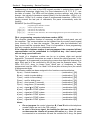
The zones (input lines) can perform the following functions in the system:
0
- ENTRY/EXIT , the violation of which, when in the armed mode, will start countdown of
the entry delay time and will enable the delay mechanism for “interior delay” type
zones (violation of an “interior delay” zone without prior violation of the "entry/exit"
zone will trigger an alarm immediately). Upon violation, a “zone violation” code is
sent to the station (it is possible to skip sending this message), and, after counting
down the "entry delay time" and triggering the alarm - a “zone alarm” code. The
"entry delay " countdown can be signaled in the keypad. It is possible to define
automatically bypassing zones if no „entry/exit” zone is violated during the exit delay
time”. Because of its additional functions, this zone type cannot be used as a
common zone for several partitions.
1
- DELAY - when violated in the armed mode, it starts delay countdown, after which an
alarm is triggered. It will not occur if the zone is disarmed before completion of the
delay countdown. Upon violation, a “zone violation” code is sent to the station (it is
possible to skip sending this message), and, after counting down the "entry delay
time" and triggering the alarm - a “zone alarm” code. The delay is not signaled in
the keypads.
2
- INTERIOR DELAY - when violated in the armed mode after previous violation of the
ENTRY/EXIT zone, it behaves like a DELAY zone. When violated in the armed
mode without previous violation of the ENTRY/EXIT zone, it behaves like an
INSTANT zone.
3
- INSTANT - when violated in the armed mode, it immediately triggers an alarm and
sends a ”zone alarm” message to the monitoring station.
4
- DAY/NIGHT - when violated in the armed mode, it behaves like an INSTANT zone,
while when disarmed, it will signal violation in the keypad (unless the signaling is
disabled) and send a “zone violation” code to the station.
COUNTING L1 - when violated in the armed mode, it increases the status of the first
of three violation counters (a „zone violation” code is sent to the station), until the
number of violations specified for that counter is exceeded (programming in FS-7).
Then, the violation triggers an alarm (a „zone alarm” code is sent to the station).
The violation counter is reset after 30 seconds since the first violation. It is possible
to program another counter count-up time (FS-123). If the preset number of
violations is not reached within this time, there will be no alarm. The "counting L1"
function can be assigned to more than one zone, then violations of those zones will
be summed up. Violation of the counting zone in armed mode can be signaled in
the keypad in the same way as for the DAY/NIGHT zone.
5
-
6
- COUNTING L2 - operation identical as for the "counting L1", but changes the status of
the second of the three counters.
7
- COUNTING L3 - operation identical as for the "counting L1", but changes the status of
the third of the three counters.
8
- 24H AUDIBLE - armed all the time, irrespective of whether the partition it is assigned
to is armed, or not. Each violation of this zone will trigger alarm on the BURGLARY
alarm type outputs, in the keypad, and will send a “zone alarm” code. It makes
possible to create anti-tampering circuits and panic buttons.
9
- 24H AUXILIARY - armed all the time, irrespective of whether the partition it is
assigned to is armed, or not. Each violation of this zone will trigger an alarm in the
Section 1 - Description of the Control Panel
7
keypad and will send a “zone alarm” code. It is intended for connecting detectors
not related to the burglary alarm, such as gas or flooding sensors, etc.
10 - 24H SILENT - armed all the time, irrespective of whether the partition it is assigned to
is armed, or not. Violation of this zone will only send a “zone alarm” code to the
monitoring station.
11 - 24H FIRE - armed all the time, irrespective of whether the partition it is assigned to is
armed, or not; intended to manage the fire detectors.
If the control panel contains a zone programmed as the "fire power supply",
violation of the zone will actuate the alarm verification mechanism and will signal
alarm in the keypad. To perform the verification, disconnect momentarily power
supply to the fire detectors and check, whether after reconnection of power supply
the violation will be repeated within 90 seconds. If that’s the case, the control panel
will send a „zone alarm” message to the monitoring station, activate the “fire alarm”
outputs, and trigger the fire alarm (intermittent signal) in the keypad.
If there are no fire detector supply zones, the zone violation will immediately send a
„zone alarm” code to the monitoring station, activate the "fire alarm"
and "fire/burglary alarm " type outputs, as well as trigger the fire alarm (intermittent
signal) in the keypad.
12 - ARMING - violation of this zone will arm the partitions the zone belongs to.
13 - SILENT ARMING - violation of this zone will arm in silent mode the partitions the zone
14 15 16 -
belongs to.
DISARMING - violation of this zone will disarm the partitions the zone belongs to.
NO ALARM ACTION - violation of this zone will activate the "zone violation" type
outputs.
ARMING/DISARMING – controls arming/disarming of partition to which this zone is
assigned. Setting of "PRIORITY" option allows to choose one of two different
modes:
-
PRIORITY option enabled: zone violation will arm the partition, while end of
violation will disarm the partition ("Bistable" action)
-
PRIORITY option disabled: each violation of the zone will trigger partition's state
between "Armed" and "Disarmed" state ("Monostable" action).
17 - DELAY AUDIBLE – a delayed zone with the delay countdown signaling in keypads.
18 - AUTOMATIC BYPASS ARMING – violation of this zone arms the partition the
zone belongs to, simultaneously bypassing the zones programmed as AUTOBYPASS (see service functions 16,17,18,19)
19 - PERIMETER – zone armed since entering the access code and confirming it with the
[#] key (i.e. arming the partition). Violation of this zone during countdown of the „exit
delay” will trigger an alarm.
20 - ENTRY/EXIT-FINAL – acts much like the type 0 (entry/exit) zone, but the violated
zone RESTORE during exit delay countdown will stop the countdown and begin the
partition armed mode.
Reaction time for each zone can be programmed within 0.016 s to 4.08 s.
For each of the delayed zones, an individual time delay can be set.
Each zone involves a few options to determine the reaction in particular situations.
It is possible to determine for each zone the maximum violation time (in seconds),
after which the zone will be recognized by the control panel as defective, and to
determine the maximum "no violation" time (in hours), after which the zone will be
recognized by the control panel as defective.
The zones can be selectively bypassed.
Seven event codes to be sent to the monitoring stations can be determined for each
zone.
8
Installation Guide
CA-10 plus SATEL
Outputs
The CA-10 plus is equipped with 6 programmable outputs: 4 high-current and 2 lowcurrent ones.
The OUT1, OUT2, OUT3 and OUT4 outputs are protected by special electronic
fuses with current limiters set at 2.2A. The panel monitors presence of voltage,
overload, and signals trouble conditions at these outputs. 2.2kΩ resistors must be
connected in parallel to these outputs. The above outputs supply the load with +12V
voltage.
The OUT5, OUT6 (low-current, up to 50mA) outputs control ground of the load.
All outputs are equipped with protective devices for inductive loads and pulse
interference.
Designation of the outputs can be adapted for the needs of the alarm system
controlled by the panel. Though individual outputs differ by their design, each of
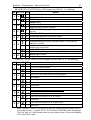
them can perform one of the following functions:
1
- BURGLARY - the output starts on detecting a burglary alarm by the control panel. The
alarm is triggered by armed zones, zone anti-tampering circuits, keypad tamper
detectors, and by the user (through the ALARM PANIC function). If the zones to
which the output is to react are defined, the zone alarms will be limited to those
included in the „list of outputs” (the other alarms will be effected irrespective of the
source). It is also possible to indicate (in the output options) the partition the output
is associated with. If this is the case, the zone alarms will be limited to those from
the zones belonging to the partition indicated. When the "list of outputs" is empty
and no partitions are indicated, the output reacts to all alarms (except for the fire
alarms).
The output can remain active for a specified time (from 01 to 99 seconds or from
01 to 99 minutes) or until the alarm is cleared by the user. During its operation, it
can every second change its state (pulsate).
2
- FIRE/BURGLARY - the output starts on detecting by the control panel of a burglary
alarm (continuous signal) and/or a fire alarm (intermittent signal). The output
operation can be limited to the indicated "list of outputs" or a specific partition
(identically as for the 01 output type). The output can remain active for a specified
time (from 01 to 99 seconds or from 01 to 99 minutes) or until the alarm is cleared
by the user.
3
- FIRE - the output starts when the control panel detects a fire alarm. Such an alarm is
triggered by fire zones or the user (through the ALARM FIRE function). The output
operation can be limited to the specified "list of outputs" or particular partitions
(identically as for the 01 output type), indication of any zones other than the fire
ones having no sense, as they would not generate a fire alarm. The output can
remain active for a specified time (from 01 to 99 seconds or from 01 to 99 minutes)
or until the alarm is cleared by the user. During operation, it can every second
change its state (pulsate).
4
- KEYPAD ALARMS - the output starts on detecting any keypad alarm (FIRE, PANIC,
AUX., keypad tamper alarms). The output operation can be limited to the alarms
from specified partitions. The output can remain active for a specified time (from 01
to 99 seconds or from 01 to 99 minutes) or until the alarm is cleared by the user.
During its operation, it can every second change its state (pulsate).
5
- KEYPAD FIRE ALARM - the output starts on triggering the fire alarm by the user
(with the FIRE ALARM function). The output operation can be limited to the alarms
from specified partitions. The output can remain active for a specified time (from 01
to 99 seconds or from 01 to 99 minutes) or until the alarm is cleared by the user.
During operation, it can every second change its state (pulsate).
6
- KEYPAD PANIC ALARM - the output starts on triggering the PANIC alarm by the
user. The output operation can be limited to the alarms from specified partitions.
The output can remain active for a specified time (from 01 to 99 seconds or from
01 to 99 minutes) or until the alarm is cleared by the user. During operation, it can
every second change its state (pulsate).
Section 1 - Description of the Control Panel
7
9
- KEYPAD AUX. ALARM - the output starts on triggering the alarm by the user with
the ALARM AUX function. The output operation can be limited to the alarms from
specified partitions. The output can remain active for a specified time (from 01 to 99
seconds or from 01 to 99 minutes) or until the alarm is cleared by the user. During
operation, it can every second change its state (pulsate).
8
- KEYPAD TAMPER ALARM - the output starts on detecting violation of the tamper
contact or a change of the keypad address,
output operation can be limited to the alarms
can remain active for a specified time (from
minutes) or until the alarm is cleared by the
second change its state (pulsate).
9
and also after 3 wrong codes. The
from specified partitions. The output
01 to 99 seconds or from 01 to 99
user. During operation, it can every
- DAY/NIGHT + COUNTING - the output starts on detecting violation of disarmed
DAY/NIGHT zone or violations of COUNTING zones, which trigger no alarm.
Operation of the output can be restricted to a specified “list of outputs” or particular
partitions (identically as for the 01 output type). Indication of any other zones than
those tested by this output type is irrelevant - they will give no violation signal. The
output can remain active for a specified time (from 01 to 99 seconds or from 01 to
99 minutes) or until the alarm is cleared by the user. During operation, it can every
second change its state (pulsate).
10 - DURESS alarm - the output starts on using an access code with authority level 4
(DURESS) to disarm the system or to signal an alarm. This code is used to trigger
a special "disarm under duress" alarm. Operation of the output can be restricted to
alarms from particular partitions. The output can remain active for a specified time
(from 01 to 99 seconds or from 01 to 99 minutes) or until the alarm is cleared by the
user. During operation, it can every second change its state (pulsate).
11 - CHIME - the output starts on violating the disarmed zones for which the “chime” option
has been activated. Operation of the output can be restricted to the indicated "list of
zones" or to specified partitions (identically as for the 01 output type). The output
can remain active for a specified time (from 01 to 99 seconds or from 01 to 99
minutes) or until the alarm is cleared by the user. The output signals violations
irrespective of the chime lock setting in keypad (the lock is activated with the
function 8, called by holding down the key).
12 - SWITCH MONO - the output is activated by calling the user function 7 ([CODE][*][7])
or using a code with authority level 5 ([CODE][#]). Operation of the output can be
restricted to specified partitions. The output can remain active for a time from 01 to
99 seconds or from 01 to 99 minutes.
13 - SWITCH BI (ON/OFF) - the output changes its state when the user function 8 is
called or a code with authority level 6 is used. Operation of the output can be
restricted to specified partitions.
14 - ARM STATUS - the output is active in the armed mode. Operation of the output can be
restricted by indicating a „list of zones” or specific partitions. Unless zones and
partitions are indicated, the output is active when any partition (zone) is armed.
15 - SILENT ARM STATUS - the output is active in the silent armed mode. Operation of
the output can be restricted by indicating a „list of zones” or specific partitions.
16 - EXIT DELAY WARNING - the output is active during the „exit delay” countdown by
the control panel. Operation of the output can be limited to indicating the „exit delay”
for specified partitions.
17 - ENTRY DELAY WARNING - the output is active during the „entry delay” countdown.
Operation of the output can be limited to indicating the „entry delay” for specified
partitions.
18 - TEL. USAGE STATUS - the output is active when the control panel is on the
telephone line.
19 - GROUND START - the output activated by the control panel to generate the
GROUND START pulse (a 2 sec. signal occurring before the control panel "lifts the
handset", required by a specific type of telephone exchanges).
20 - MONITORING CONFIRMATION - the output activated for 3 seconds by the control
panel, after correct termination of the monitoring session.
10
Installation Guide
CA-10 plus SATEL
21 - BYPASS STATUS - the output is active when some zones are bypassed in the
system. Operation of the output can be limited to showing the bypass of zones
specified in the list of zones, or the bypass of indicated partition zones.
22 - READY STATUS - the output is active when all the control panel zones are free from
violations. Operation of the output can be limited to showing the READY status of
zones specified in the list of zones, or the READY status of indicated zones.
23 - ZONE VIOLATION - the output starts when one of the zones is violated. Operation of
24 -
the output can be limited to the indicated "list of zones" or specified partitions
(identically as for the 01 output type). The output can remain active for a specified
time (from 01 to 99 seconds or from 01 to 99 minutes) or until the armed mode is
deactivated or the alarm cleared.
TELEPHONE LINE FAULT - the output used when telephone messaging is doubled
by radio messaging; it makes possible reporting the telephone line faults.
25 - 230V AC LOSS INDICATOR .
26 - LOW BATTERY INDICATOR – activated when the battery voltage in three
consecutive tests drops to about 11V.
27 - POWER SUPPLY - the output intended for powering detectors, encoders, radio lines
28 -
and other equipment with 12V direct voltage. When programming this type of
output, pay special attention to permissible current-carrying capacity of each of the
control panel outputs.
FIRE POWER SUPPLY - the output intended for powering the fire detectors. The
output closely interacts with the 24H FIRE zones. If assigned to any of the control
panel outputs, the function activates the fire alarm verification mechanism. The
mechanism operates as follows: the first violation cuts the fire detectors power
supply off for about 15 seconds. The power-down results in reset of the violated
detectors. Then, the power supply is restored, but the panel will not control the 24H
FIRE zones for ten to twenty seconds because of the balancing of detectors. Next,
the control panel enters the special mode of fire detectors control, which lasts about
90 seconds. If a repeated detector violation occurs during that time, a FIRE alarm
will be triggered. Otherwise, the control panel will go over to the normal control of
24H FIRE zones. The output reacts to the "RESET POWER SUPPLY" function
(user function 9, cutoff for time programmed as the output active time).
29 - RESET POWER SUPPLY - the output is designated to power detectors which
require a periodical power cut-off until the state memory is cleared. The RESET
mechanism is activated from keypad through the user function 9 (calling:
[CODE][*][9]). The voltage is cut off for time programmed as the output active time
(minimum 5 seconds).
30 - TIMER - the output is controlled by the control panel clock; it is activated / deactivated in
the hours indicated by a corresponding TIMER (see Functions programming
TIMERS).
31 - AUDIBLE ALARM STATUS - the output signals the audible armed mode. Operation
of the output can be limited to the indicated "list of zones" or specific partitions.
32 - FULL ARM STATUS - the output is only active when all zones / partitions assigned to
it are in the armed mode.
33 - ARM/DISARM/CLEAR ALARM - the output signals the performance of particular
operations with, respectively, one, two, or four pulses 0.16 s each.
34 - KEYPAD ALARM BUZZER - silent alarm signaling in the partition keypad.
35 - POWER SUPPLY IN ARMED MODE - it functions similarly to the arm status
output, but goes on right after starting the exit delay countdown, not after
changeover from the exit delay to the armed mode (it can be used, for example, as
indicator or power supply output for microwave detectors in spaces where people
stay).
36 - STATUS LED – the function used in the CIS countries.
37 - STATUS RELAY – the function used in the CIS countries.
38 - ZONE TROUBLE – the output signals that the maximum zone violation time or the
maximum zone no violation time have been exceeded.
Section 1 - Description of the Control Panel
11
39 - NO GUARD CODE – the output is activated by a timer programmed as the partition
control TIMER, unless a guard code is entered within the timer specified time.
40 - SERVICE MODE INDICATOR – the output is activated if the control panel service
mode has been called from any keypad.
41 - LOW BATTERY INDICATOR – the output whose state is updated after each
battery voltage test.
Operation time can be defined for each output in seconds (from 1 to 99 seconds), in
minutes (from 1 to 99 minutes), or LATCH type (until cut off). It is possible to
determine the output polarity for active state (+12V or 0V on the load), and whether it
should operate in pulsed or continuous mode.
Assignment of the particular outputs can be restricted to the specific partitions /
zones of the system.
Keypads
The keypads are designed for operating and programming the system (or
a partition). The CA-10 plus can support four independent LCD or LED keypads, thus
making possible creation of four partitions or separate systems. Each keypad is
assigned to one partition.
The keypad operating mode is set when programming the panel. It is possible to
disable some of its functions (e.g. the quick arming by pressing in turn the [0] and [#]
keys), and determine what audible signals are to be provided by the keypad.
The keypads have addresses, which make difficult replacement or connection of
another keypad, an individual anti-tampering contact and two zones, which operate
identically as the zone inputs of the control panel main board. They can be assigned
to any partition.
The data concerning the address, anti-tampering contact status and zone status, are
sent to the control panel together with keypad data.
LCD Keypad
The CA-10 plus control panel is designed to work with an LCD keypad with
software version v2.00 (or later). The LCD keypad provides information on the
alarm system status by means of a two-line (2 x 16 characters) LCD display and,
additionally, six LEDs.
The LED functions:
• ALARM - signals an alarm occurrence.
• TROUBLE - blinking, when the control panel signals detection of a technical
problem or a telephone messaging problem.
• PARTITION 1 ... PARTITION 4 - show the partition status: blinking (with the
ALARM LED off) means the exit delay countdown; steady light means the
armed mode of the partition.
The LED functions change when calling the service mode or entering the user
functions mode – they are in keeping with the principles of status display by the
control panel LED keypads.
The keypad is provided with 12 keys, designated according to the telephone
standard, and intended for entering data. The additional 4 arrow keys in the LCD
keypad allow the user to move through the MENU and to select functions. When
the function is selected, these keys facilitate programming. The Õ Ö keys change
the cursor position, the × key deletes the character before the cursor, whereas
the Ø key changes the data entry mode (adding or changing at the cursor
position).
12
Installation Guide
CA-10 plus SATEL
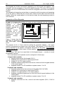
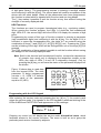
Three operating modes of the keypad are provided:
1) Text mode. The first line of the display shows the system date and time. The
second line contains messages on the system state. The contents of messages
can be either standard (e.g. SYSTEM OK., ARMED), or customized by the
installer. This mode enables the status to be displayed either with or without
priority. In the priority mode, the most important information message from
among a few relevant ones (e.g. ALARM !) will be constantly on. In the nonpriority mode, the display state will change cyclically (e.g. the messages
THERE WAS ALARM and ARMED will be displayed alternately).
2) Zone state display - LCD standard. The first line of the display shows the
system date and time, while the second serves for monitoring the state of all
the 16 zones of the control panel. The zone state is determined by a displayed
character (for example: = zone OK., N = zone violated). At the moment of
changing the system state (e.g. when the system is armed), the display shows
the status for a while, much in the same way as in the previous mode, then the
keypad returns to monitoring the state of zones.
3) Zone state display - LED standard. This mode is similar to the mode 2). The
difference is that the state of 12 zones of the control panel is being monitored in
the second line in the same way as it is the case in the LED keypad.
The operating mode 1 or 2 is recommended for the LCD keypad. The user can
temporarily switch the display between the text mode and the zone state mode by
holding down the Ø key.
The operating mode is defined by the installer with the State format service
function, available only after activation of the control panel service mode.
The LCD keypad is fitted with a RS-232 port intended for programming the keypad
directly from the computer.
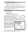
LED Keypad
In the LED keypad, the state of partition and selected zones is displayed by
means of LEDs. Indication of any 12 zones of the control panel is possible for
each partition. The other three LEDs have fixed meanings: the red one signals
ALARM, the green one ARMED mode (blinking means the exit delay countdown),
and the yellow one TROUBLE.
Access Codes and Authority Levels
The CA-10 plus panel can store in memory 32 access codes (4 to 6 digits long), with
different authority levels. The codes are associated with the partitions they are
assigned to. The control panel has a MASTER code initialized when restarting with
the control panel settings (four-digit access code, beginning with a digit equal to the
partition number, 1234 for Partition 1, 2345 for Partition 2, etc.). The master code
cannot be deleted, however it can be changed. It provides access to all user
functions.
The master code user (User 0) can add new users, assigning various authority levels
to them. The code authority level defines which functions of the control panel are
accessible by using this code, and which are not.
New users (new codes) are automatically numbered by the control panel as they are
entered. This makes it possible to distinguish, who and when operated the control
panel, as the user (code) number is stored in the memory of events along with the
command given. With the LCD keypad, identification of the users by their name is
also possible.
Section 1 - Description of the Control Panel
13
Deletion of the code will not cause renumbering of the other users’ access codes.
Whenever a new user is added, his code will replace the one left by the deleted user.
Access codes can be declared as the „global access codes” (FS 131). Then they will
be accepted in each partition, irrespective of in which partition they are entered.
However, with this option it is impossible to identify the user who called the control
function when viewing the event log.
Individual users may have the following authority levels:
1 - accessible all functions, except creating and deleting users,
2 - accessible arming and disarming, change of access code,
3 - accessible arming, while disarming is only possible when the system
was armed with the same access code,
4 - code trap: it arms and disarms the system, but disarming sends
a DURESS ("disarmed under duress") message to the monitoring station,
5 - activates the MONO SWITCH output, its use is recorded in the event
log, can serve as a guard code,
6 - changes the state of BI SWITCH output,
7 - partial arming - the code arms the system, simultaneously bypassing
a group of zones (specified by the installer in service functions), otherwise
the code provides the same features as that with authority level 2,
8 - accessible arming and disarming, without possibility to change own
access code,
9 - accessible arming only,
0 - accessible alarm clearing only.
Partitions
Creation of a partition consists in assigning at least one zone to it. The CA-10 plus
permits four partitions to be created. Any outputs, telephone numbers and pager
messages can be assigned to one partition, thus enabling four independent alarm
systems to be built on the basis of one CA-10 plus control panel.
In the event of a few keypads being connected to the control panel, each keypad will
be hooked up to the particular partition via a special control output. The keypad
connected to the CLK1 output will belong to the partition 1, that connected to the
CLK2 output - to the partition 2, etc.
Where the system comprises less keypads than partitions, individual partitions can
be operated from the existing keypads, by means of the GO TO function (when this
function is called, the keypad will for a time belong to another partition). The partition
which has no keypad, can be controlled through the zones to which the "arming" and
"disarming" functions are assigned. The state of such a partition can be signaled on
the outputs.
Partitions can be defined in the following way:
• partitions have no common zones - they are independent sub-systems,
• some zones belong to several partitions - the common zones are only armed
when all the partitions these zones belong to are armed,
• all zones of one partition belong at the same time to another partition - the
control panel recognizes one partition as the master, and the other as an
internal one; arming/disarming the master partition results in simultaneously
14
Installation Guide
CA-10 plus SATEL
arming/disarming the internal partition, while arming/disarming the internal
partition only affects the zones within that partition,
• the same zones are assigned to different partitions - these partitions will
become mutually internal; arming/disarming one partition causes identical
reactions in the other partition: thus defined partitions behave like one partition
with two (or more) independent keypads.
When analyzing, if the given partition is an internal one, the control panel checks
how the zones for which arming is possible overlap. Therefore, an internal partition
can be assigned with separate "24H" zones as well as arming control zones.
The partitions have individual identifiers and event codes for monitoring purposes.
Monitoring
The CA-10 plus control panel can transmit information about the system (partition)
status to one or two monitoring stations. Communication with the monitoring stations
takes place irrespective of the voice messaging and the messaging to paging
systems. It has a priority and is realized before the voice messaging. In case
problems occur with getting connected to the station, the control panel will suspend
dialing the station number for 60 seconds and, if the message is also to be
transmitted by the dialer, it will make the line available to the dialer.
There are a few ways of transmitting information to the monitoring stations.
• Reporting to one station.
• Reporting to Station 1, and if unavailable - to Station 2 (e.g., when the
station has two telephone numbers). If this is the case, all events are reported,
irrespective of which station was reached by the control panel.
• Reporting to both stations with event sorting - depending on what event
occurred in the system, e.g. information on alarms to Station 1, and
information on troubles to Station 2 (this mode is useful where the station
serves many subscribers and it is necessary that the number likely to receive
most vital information be busy as little as possible). In this mode, during control
panel programming, you can determine which information is to be sent to
which station.
• Reporting to both stations: Station 1 first, then Station 2. This mode is
reached by assigning the same event to both stations.
In case of a system with 16 zones and 32 users, the number of messages to be sent
to the monitoring station in order to ensure an appropriate facility protection degree
may be large enough to exceed the capacity of standard transmission formats.
Therefore, to increase the control panel flexibility, the events occurring in the system
have been divided into six groups:
• the first one includes the zone related events (this group has the highest
priority),
• four groups are represented by the partition related events (the event priority
depends on the partition number, the first partition having the highest priority),
• the sixth group accounts for the other system events.
Individual system identifiers are assigned to each group of events (one for each
station). In the event of stations which cannot accept several different identifiers in
one communication session, the control panel can send the events in separate
sessions, in the order resulting from the priority, grouping events with the same
identifiers.
It is possible to send information on nine different zone related events and seventeen
partition related events (whereof seven events may contain the user number). The
control panel is also capable of sending twenty eight other events which occurred in
Section 1 - Description of the Control Panel
15
the system (e.g. troubles, start of programming mode via a telephone, activation of
service mode, etc.). The event codes for both stations are the same. For a majority
of events, it is possible to define how the events are to be sorted between the two
stations. Information can be sent to the stations in one of the seventeen transmission
formats (including the TELIM format, used in Germany).
Because of the analysis of commutation signals (algorithm ToneLOGIC), the
CA-10 plus panel controls the process of establishing connection with the station,
which in case of the line being frequently busy considerably reduces the time
between occurrence of the event and sending information to the monitoring station.
As dialing retries are made immediately after detecting the busy signal, the
connection is established many times faster than with the equipment which waits for
one specific signal for a predetermined period of time and only redials upon
detecting that that signal has not occurred .
Dialer
The CA-10 plus control panel is equipped with a telephone dialer, which enables an
alarm voice message to be transmitted. The message is stored in an external
synthesizer. The control panel directly interfaces with the SM-2 voice synthesizer.
The dialer can also establish connections with paging systems. Four different
alphanumeric messages can be programmed.
The CA-10 plus allows programming of eight telephone numbers, 16 characters
each.
It is possible to define for each number, which partitions signal alarm at that number
and assign to it one of the four text messages for the pager or a voice
announcement from the synthesizer.
During the procedure of connection setup, the ToneLOGIC system used in the CA10 plus panel controls sound signals from the telephone line. Hence, it can recognize
that the call is answered, irrespective of the type of telephone exchange.
Messaging for each telephone number is realized in accordance with the following
parameters:
• Number of queues (1 to 7) – defines how many times it is necessary to call
and send information to each number,
• maximum number of retries (1-9) – number of attempts, after which the
panel will stop dialing the number, for which connection cannot be established
(no answer, permanently busy, etc.).
When waiting for the dial tone during dialing (code D, when the control panel is
connected to an extension line and is trying to get the outside line), detecting the
busy signal does not decrease the counter of queues and attempts.
The control panel dialer can also perform the function of answering the calls
and reporting the system state (see functions FS-5 and FS-101):
• with a sound signal: one beep a second if there was no alarm,
• with a voice message (if one hour has not elapsed yet after the alarm),
• with a sound signal: five short beeps every second if at least one hour has
elapsed from the alarm.
Another way of getting information on the system state via the telephone is through
the control panel operation in conjunction with the SATEL MST-1 module (see: FS131, option 2). Additionally, this module enables the system to be remotely
controlled, within certain limits, by means of DTMF signals (see User Manual for the
CA-10 plus alarm control panel with LED Keypad). For the connection diagram refer
to the MST-1 module operating instructions.
16
Installation Guide
CA-10 plus SATEL
Remote Programming – DOWNLOADING
In order to facilitate programming, the CA-10 plus panel is equipped with
a DOWNLOADING mechanism, which enables a PC computer to be used for
programming and service control of the alarm system.
Operation with the computer can be realized in two ways: in the „local mode” by
means of the RS-232 interface (after connecting the CA-10 plus directly to one of the
computer COM ports), or in the „remote mode”, via the telephone line (in this case
the computer must be equipped with a modem).
Programming the data of LCD keypad is available in the local mode through the
RS-232 port on the keypad board.
The DLOAD10 program, delivered with the panel, supports both operating modes.
The DLOAD10 program enables:
• downloading (reading) all control panel parameters,
• uploading (writing) new parameters to the control panel,
• downloading (reading) the system event log.
The program does not read or change the user access codes - these are only
accessible through the user functions from keypads.
In the ONLINE mode, the computer displays current information on the system state,
including zone violations, active outputs, control panel clock, and selected partition
state. Provision is made for controlling the system in the same way as with a LED
keypad. The computer screen keypad works in parallel with the real keypads in
partitions, therefore commands for all partitions can be given from one place. The
ONLINE mode also permits downloading troubles and programming the clock.
Communication in the local mode (through the RS-232 port) is started with a special
service function (FS 112). Connection can also be initialized without using the
keypad (e.g. if it is located far from the control panel and the computer). This can be
achieved using the "Local connection with…" command in the DLOAD10 program.
Communication through the telephone line can be initialized in three modes:
1) The computer calls the control panel, which after answering the call exchanges
handshake signals with the computer. When they are correct, the panel
confirms acceptance of the remote programming command, hangs up and
calls back to the computer using a number preprogrammed in the control
panel. Prior to calling the computer back, the panel notifies the monitoring
station that the programming has started.
2) The computer calls the control panel and, after the handshake, the control
panel immediately proceeds to the exchange of data. This simplified mode of
establishing communication is reached when the computer telephone number
is not entered in the control panel. Notification of the monitoring station will
take place after communication with the computer is over.
3) Establishing of communication from the control panel by calling the function 0
(zero) by the partition master user. The control panel first notifies the
monitoring station that the programming has started (when monitoring is
active), then it dials the computer telephone number.
Initialization of communication can be disabled from the computer.
In order to reduce the cost of telephone connections, multiple suspension of the
transmission is possible. At the next connection, the control panel does not inform
the monitoring station of remote programming. Only after receiving the command to
end the communication, a message on completing the remote programming is sent
to the station. Initialization of communication can be disabled from the computer.
When the communication is suspended from the computer, the control panel is
Section 1 - Description of the Control Panel
17
waiting for a call from the computer for four hours even when the functions of
automatically answering the computer call are disabled. When the communication is
ended with the “end” command instead of “suspend”, the information on ending the
communication is entered into the event log and sent to the monitoring station after
four hours.
As the control panel is only accessible to the service, a number of protective devices
is provided to prevent hacking of the system and change of any data by unauthorized
persons. All the data exchanges are authorized by changing the access codes and
the data are encoded.
The DOWNLOADING can be particularly useful to installation firms engaged in
servicing many alarm systems. Then the user suggested inspections and
modifications of software will not necessarily require troublesome and costly traveling
- they will be carried out with a computer via the telephone line. Such a method of
customer service and technical control of customer systems will allow creation of
alarm equipment services at an advanced and professional level.
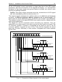
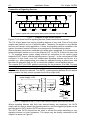
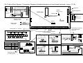
INSTALLATION OF THE CONTROL PANEL
Description of Control Panel Main Board
The control panel main board contains electronic components sensitive to electric
charges. Prior to installation, these charges must be removed. During installation,
avoid touching any elements on the control panel main board.
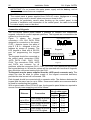
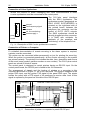
BOARD TERMINALS:
AC
- module power supply inputs (17...24V AC)
Z1 to Z8
- zone inputs
OUT1 to OUT4 - programmable outputs (current-carrying capacity 2.2A)
OUT5 to OUT6 - programmable outputs (current-carrying capacity 50mA)
+KPD
- keypad power supply output
+12V
- power supply outputs
COM
- ground
DATA
- common terminal of keypads
CLK1 to CLK4 - individual terminals of separate partition keypads
- protective terminal - ground (connect to protective circuit only)
TIP, RING
- terminals of outside telephone line
T-1, R-1
- terminals of extension telephone line (telephone set)
J22
- connector for OUT5 & OUT6 output, power supply and ground
lead-outs
J18
- connector for SM-2 voice synthesizer
(BLACK)
(RED)
BATTERY
Z3 COM Z4
AC AC COM OUT1 COM OUT2 COM OUT3COM OUT4COM+KPD DATA CLK1CLK2CLK3CLK4 COM Z1 COM Z2
J24
RS 232
RESET
J19
350mA
700mA
J20
DIALER
5W0.1ΩJ
Z5 COM Z6 Z7 COM Z8
J22
SM-2 VOICE
SYNTHESIZER
J18
R-1 T-1 RING TIP
CA-10 plus SATEL
+12V
+12V
OUT5
OUT6
COM
Installation Guide
BATTERY
CHARGE
18
T3.15A
1 - Diagrammatic view of control panel main board, version CA10PV4.3.
The AC terminals are intended for providing the alternating supply voltage from the
mains transformer. The control panel power supply unit is suitable for the 17...24V
AC input voltage. The control panel is fitted with an advanced pulse-type power
supply of high energy efficiency and operational reliability, however, its correct
functioning requires that the input voltage at the maximum load of the transformer
by the control panel does not drop below 16V AC.
The CA-10 main board can be connected to an electric shock protection circuit
(grounding). The protective cable terminal is designated by the
symbol. The
„neutral” wire of the 230V AC mains supply must not be connected to it. If the facility
has no separate electric shock protection circuit, this terminal must be left free.
The control panel power supply is fitted with:
battery status monitoring system with optional disconnection of discharged
battery,
visual signaling of the battery testing/charging process (LED indicator on the
main board),
changeover battery charging current (350mA/700mA).
Figure
Section 2 - Installation of the Control Panel
19
BEND ASIDE
BEND ASIDE
The stabilized voltage of the control panel power supply is 13.6 - 13.8V and is factory
set.
The „DIALER” LED is on during telephone messaging by the panel, and blinks during
pulse dialing of the telephone number.
The BATTERY CHARGE LED situated next to the „J20” pins is on when the battery
status is being tested by the module and during charging of discharged battery.
CA-10 tests the presence of battery every 10 seconds and every 4 minutes it tests
(for several seconds) the battery status. During testing, the processor reduces the
power supply and the loads are powered from the battery. If the battery voltage
drops down to 9.5V, the control panel will cut off the battery in order to prevent it
from a complete discharge and damage.
The J20 pins are used for setting the battery charging current:
350mA
- pins shorted,
700mA
- pins open.
Two wires (red and black) are intended for connecting the battery, the red one is
connected to the battery „+” terminal, the black one to the „-” terminal. The battery
circuit is protected with a T 3.15A fuse.
The J19 „RESET” pins make it possible to start the service mode without entering
any service code. This function can be disabled by the installer with software means
(see: FS 131 - Option 1).
Electronic short-circuit and overload protection is provided for each of the outputs
OUT1-OUT4 and +KPD.
Attention should be paid so as not to cause overloading of the control panel power
supply in the alarm system. It is advisable to make a load balance for the power
supply. The total current inputs for the consumers (detectors, keypads) and the
battery charging current may not exceed the power supply capacity. In case of a
higher electric power demand, an additional power supply can be used for some of
the security system consumers (e.g. APS -15, APS-30 manufactured by SATEL).
Table 1 (at the end of this manual) shows an example of estimated balance of
current consumption by the system, and an example of battery selection.
The telephone line must be of a four-wire type so that the control panel can be
connected before the other equipment (telephone, fax, etc.).
The CA-10 plus control panel should be installed in an enclosed space with normal
humidity of air. The space should be fitted with an available permanent (not
detachable) 230V power supply circuit with protective grounding.
The control panel can be mounted in the CA-10 OBU housing (this housing
comprises a transformer designed for operation with the control panel power supply),
which permits installation of a battery with 17Ah capacity. Before
the housing is secured to the base, it is necessary to mount
inside the housing plastic distance plugs, which are intended for
subsequent installation of the main board.
In case the plugs tend to slip out, the catches fixing the plug in
the housing need to be slightly bent aside (Figure 2). When
inserting the plug, press the central part of the head firmly in so
that it is blocked in the housing hole. It is advisable to make sure
that the plug, when pressed, does not slip out from the opening.
During installation of the housing, be careful so as not to damage
PRESS IN
the wires which will be passed through the hole in its back panel.
Figure 2
When the housing is secured, you can install the control panel main board and
proceed to making the connections.
20
Installation Guide
CA-10 plus SATEL
IMPORTANT: Do not connect the mains power supply and the battery, until all
the remaining connections are completed.
CAUTION!
The control panel is power supplied from 230V AC mains. Negligence or wrong
connection may result in electric shock and pose a threat to life!
Therefore, be particularly careful when hooking up the control panel. In the
process of installation and connection of the control panel, the cable to be used
for mains supply must not be alive!
Connection of Keypads
The CA-10 plus control panel makes it possible to connect four independent
keypads, intended to control separate partitions. The keypads are connected to the
system by a four-wire line.
keypad address jumpers
Figure
3
shows
the
keypad
connectors: +12V, CLK, DATA, COM
designed for connection to the panel,
Z1,Z2 – detector inputs, four pairs of
D C B A
pins D C B A - designed to set the
address by means of jumpers. The
RS -232 (LCD)
Keypad
LCD keypad is fitted with a RS-232
port for programming the keypad
+KPD CLK DATA Z1 COM Z2
LED keypad
data.
illumination
The keypads should be connected to
the control panel connectors COM,
+KPD, DATA, CLK1, CLK2, CLK3,
CLK4. The connectors COM, +KPD
Figure 3
and DATA are common for all
partitions, while the connectors CLK1, CLK2, CLK3 and CLK4 determine the partition
the keypad belongs to. Where the system will be operated with less than 4 keypads,
they should be connected starting from the CLK1.
The keypads may be power supplied from the +KPD panel connector only. This
output can also be used for power supply of the keypad connected detectors,
provided the total current will not exceed 1.5A.
Each keypad should be connected with a separate cable. The distance between the
keypad and the panel can be up to 200m. Unscreened cables are recommended to
be used for connecting the keypads.
With a typical cable of the DY 8x0,5 type, the keypad-to-panel distances required to
ensure correct power supplying can be as follows:
Distance
Connection
Power supply & ground
up to 50 m CLK & DATA signals
Power supply & ground
up to 100 m CLK & DATA signals
Power supply & ground
up to 200 m CLK & DATA signals
No of cable cores
LCD
LED
keypad keypad
2x1
2x1
2x1
2x1
2x1
2x2
2x1
2x1
2x1
2x4
2x1
2x1
Section 2 - Installation of the Control Panel
21
As the LCD keypad current consumption is larger than that of the LED keypad
(particularly with active illumination of the keypad and display), it is important that
resistance of the power supply and ground lead-ins be taken into account when
planning the cabling installation.
Caution: The supply voltage measured across the terminal block of LCD keypad
with active backlighting should not be less than 11V.
The keypad jumpers determine the address which is an additional anti-tampering
protection. A different (arbitrary) address should be set in each keypad. The
panel does not accept addresses of the „all shorted” and „all open” type addresses.
The address is stored in the panel EEPROM (non-volatile) memory, together with the
other system parameters.
The keypad Z1 and Z2 connectors permit connecting any detectors. They are
supported by the control panel in the same way as the main board zone inputs. The
Z1 connector, partition 1 keypad, is recognized by the panel as zone 9, the Z2
connector, partition 1 keypad - as zone 10, etc. Thus, with four keypads, the control
panel has 16 zones. Alternately, a lower number of keypads and a zone expander
can be used.
COM +KPD DATA CLK1 CKL2 CLK3 CKL4
Control panel main board
zone 9
zone 10
Partition 1
+KPD CLK DATA Z1
COM
zone 11
Z2
keypad
zone 12
Partition 2
+KPD CLK DATA Z1
COM
zone 13
Z2
keypad
zone 14
Partition 3
+KPD CLK DATA Z1
COM
Z2
keypad
Figure 4 - Connection of three keypads to the control panel.
22
Installation Guide
CA-10 plus SATEL
The keypads are not be connected in parallel to one CLK signal (one partition - two
keypads), with the exception of the CA-10 KLED keypads. The other LCD keypads
as well as the CA-10 KLED-M and CA-10 KLED-S keypads must not be connected in
parallel.
The keypad anti-tampering contact has no connection with the system anti-tampering
circuit. Its state is defined by the control panel, based on the data received from the
keypad. When the control panel is in the service mode, the anti-tampering contact is
not controlled.
Connection of Zone Expander
In order to increase the number of zones, a zone expander can be connected,
instead of a full set of
CENTRALA
(upper pos.)
keypads.
It
makes
CA10 plus
available the zones of
AUX
CA10
keypads required for full
A B C D
C1 C2
+KPD
AUX
configuration.
The
DATA
DATA
expander
should
be
CLK
CLK
CA10E
connected as a next
TMP
keypad. It can be used in
COM
COM
LED ON/OFF
EXPANDER HOUSING
combination
with
a
ANTI-TAMPERING CONTACT
different
number
of
Z1 COM Z2 Z3 COM Z4 Z5 COM Z6
keypads.
Figure 5 shows how the
Figure 5- Zone expander.
expander is connected to
the CA-10 plus control
panel.
The jumpers A, B, C, D are used for setting the expander address – the upper
position corresponds to a jumper set in the keypad. The jumpers C1 & C2 should be
set as required by the number of keypads connected to the panel. The expander
jumpers must be set in either upper or lower position - they must not be permanently
removed.
The expander TMP input is an equivalent to the keypad tamper – normally it should
be shorted to ground.
The control panel and expander can be configured in three ways:
1 keypad and expander:
• keypad connected as first keypad (CLK1)
• expander CLK connected to control panel CLK2
• jumpers C1 & C2 in upper position
• expander address programmed as second, third and fourth keypad address
in the control panel
• expander zones Z1 to Z6 available as system zones 11 to 16.
2 keypads and expander:
• keypads connected as first and second keypads (CLK1 & CLK2)
• expander CLK connected to control panel CLK3
• jumper C1 in upper position, C2 in lower position
• expander address programmed as third and fourth keypad address in the
control panel
• expander zones Z1 to Z4 available as system zones 13 to 16.
3 keypads and expander:
• keypads connected as first, second and third keypads (CLK1, CLK2 &
CLK3)
Section 2 - Installation of the Control Panel
23
•
•
•
expander CLK connected to control panel CLK4
jumpers C1 & C2 in lower position
expander address programmed as fourth keypad address in the control
panel
• expander zones Z1 & Z2 available as system zones 15 & 16.
Where the expander is installed at a large distance from the control panel (a few
tens of meters), the power supply and ground of detectors connected to the
expander zones should be connected to the control panel with separate wires.
The LCD keypads can only interface in the alarm system with the expander
version manufactured since February 1998.
Connection of Detectors
The CA-10 plus can operate with any type of detectors. Each zone of the control
panel can work in the configuration:
• NC (normally closed),
• NO (normally open),
• EOL (one-parameter),
• 2EOL/NO (two-parameter, NO type detector),
• 2EOL/NC (two-parameter, NC type detector).
When the zone works in a one-parameter configuration (EOL), a 2.2 kΩ resistor
should be used to make the detector circuit.
With two-parameter inputs (2EOL), the detector circuit is closed by two 1.1 kΩ
resistors. The zones of 2EOL type enable the status of detector and its antitampering contact to be monitored at the same time.
The detectors may be power supplied from any of the electronically protected
outputs (OUT1 to OUT4). The output should be programmed as the "POWER
SUPPLY OUTPUT". Detectors connected to the keypad zones can be power
supplied from the +KPD output, however, care must be taken so that the permissible
load of 1.5A is not exceeded for that output.
Figure 6 shows how the detectors are
GND TAMP C NO +12
connected to the two-parameter
configuration zone inputs. Separation of
the detector power supply ground and
the line ground makes it possible to
eliminate the harmful effect of wiring
resistance. Assuming that the wire is
2 X 1,1k Ω
rather short, and only one detector is
connected to it, the installation can be
to detector power
simplified by using one wire for the
supply circuit
power supply ground (GND) and the
COM COM
Zn (detector input)
signaling ground (COM).
(power) (input)
Figure 6 - Connection of 2EOL detector.
The NO and NC detectors in two-parameter configuration are connected in the same
way, it is only important to correctly indicate to the control panel, what type of
detector is connected to the zone input (2EOL/NO or 2EOL/NC).
24
Installation Guide
CA-10 plus SATEL
Connection of Signaling Devices
+12 V
LIMITER
2.2A
COM
OUT1
LOAD
COM
LIMITER
2.2A
OUT2
LOAD
COM
OUT3
LOAD
LIMITER
1.5A
LIMITER
2.2A
LIMITER
2.2A
COM
OUT4
COM
+KPD
LOAD
Caution: outputs OUT1, OUT2, OUT3 & OUT4 must be loaded with resistors 2.2 k
Ω
Figure 7 - Diagram of high-current outputs.
Figures 7 & 8 show how the signaling devices (loads) should be connected.
The CA-10 plus panel can control signaling devices of any kind. Each of the panel
outputs can perform any of 41 different tasks. Therefore, the system is very flexible
and can suit almost every application. If there are signaling devices installed in the
system, the alarm function will have to be assigned to corresponding outputs.
Where signaling devices are used that give alarm when energized, it is convenient to
assign the alarm function to one of the outputs OUT1 to OUT4. If this is the case, the
"+ " of signaling device power supply should be connected to the control panel
respective OUT output, and the signaling device "ground" - to the control panel COM
connector. In this mode, even four independent signaling devices can be set. It is
possible e.g., after programming one output for operation during a preset time, and
the other for operation until cut off, to control the audible / visual signaling device.
The outputs OUT1 to OUT4 perform monitoring for the presence of a load. For their
correct operation, the connected signaling devices must incorporate a parallel 2.2kΩ
resistor. If there are undesired low sounds in disconnected signaling device, this
resistor value should be reduced. The SATEL made signaling devices do not require
such a resistor, as they ensure a proper level of the output load.
+12V
power supply +12V
+ Ucc
R
OUT n
OUT5
GROUND SHORTING
OUTPUT
OUT6
LOAD
50mA
COM
+12V
OUT n
P
RELAY
OUTPUT
Figure 8 - Diagram of OUT5, OUT6 low-current outputs and load connection.
Where signaling devices with their own internal battery are employed, the OUT4
output can be used to power the signaling devices, and the triggering signals can be
provided by the OUT5 and/or OUT6 low-current outputs.
The OUT5 and OUT6 outputs can be used to control the relays switching on any
signaling devices or other equipment. The relays may be directly connected to the
outputs, as shown in Figure 8.
Section 2 - Installation of the Control Panel
CA-10 plus
low-current outputs
connector
25
NR2-DSC transmitter socket
(PGM)
(TAKT)
8
15
14
13
output OUT5
output OUT6
12
2
9
1
to battery "+"
fuse WTAT250V/2A
DB-15
to mainboard AC contact
to ground contact COM (next to contact OUT1)
Figure 9 - Connection of NR2-DSC controlled transmitter, made by NOKTON s.c.
The OUT4 and OUT5 outputs can also be used to control the NOKTON NR2-DSC
radio monitoring transmitter (NEMROD system - format PC16OUT). In such a case it
is necessary to change the operating mode of these outputs by activating a suitable
option in the service function 5. During operation with the NOKTON transmitter, the
outputs are used for transmitting a number of data on the control panel state (zone
alarms, fire alarms, troubles, armed mode, etc.) and do not perform functions
programmed with the standard service functions.
Note: When hooking up any equipment with a considerable current consumption
(e.g. a radio monitoring transmitter) to the control panel, their "+" should be
connected to the battery "+" (a fuse is recommended on the feeder cable).
The ground must be connected to any COM contact of the control panel,
but not directly to the battery "-". If connected to the battery "-", the ground
will actuate the charging current limiter, eventually causing quick discharge
of the battery.
Connections of Telephone Line
If the control panel telephone communicator is used in the alarm system (for
monitoring, messaging or remote programming), it is necessary to connect telephone
line to the control panel. It should be led to a connector situated on the right side of
the printed board. In order to ensure proper messaging, the control panel must be
directly connected to the line (connectors designated as TIP and RING), and any
other devices (telephone, telefax) - after the control panel (connectors designated as
T-1 and R-1). Such a connection will make it possible for the control panel to fully
engage the line for the time of calling, which prevents the messaging function from
being blocked by lifting the handset. Additionally, the telephones connected after the
control panel do not signal the dialing by the control panel.
CAUTION!
• Do not send telephone signals and alarm system signals by one multicore
cable. This may result in a damage to the system in case of a high-voltage
punch-through from the telephone line.
• Telephone terminals of the panel should be connected to PSTN lines only.
Connecting to ISDN lines may lead to damage of the equipment.
• System installer should give the necessary information on the way of
connection with telephone network to system owner.
26
Installation Guide
CA-10 plus SATEL
Connection of Voice Synthesizer
Where the function of alarm messaging with voice announcements is used,
a voice synthesizer must be connected to the control panel.
ground
low-frequency signal
release
tel. line monitoring
power supply +
panel
board
The CA-6 plus panel interfaces
with the SM-2 synthesizer. The
synthesizer socket (designated as:
SM-2 VOICE SYNTHESIZER) is
situated on the right-hand side of
the printed board, between the
telephone line connector and the
socket of OUT5, OUT6 outputs.
The SM-2 synthesizer should be
directly plugged into this connector.
It is fitted with minijacks for
playback of the message and
"monitoring" of the telephone line.
Fig. 10 - Description of SM-2 voice synthesizer connector.
Connection of Printer or Computer
If a detailed documentation of events occurring in the alarm system is required,
a printer must be connected.
The printer can be connected either permanently or just for printing the event log.
When the printer is connected permanently, all the events occurring in the system
are printed instantly. The printout line includes the date, time, description and source
of the event (zone number, partition number or user number). The CA-10 plus control
panel can record 60 kinds of events.
The control panel is designed to control printers having an RS-232 input. On the
control panel board, the RS-232 port is linked to the J24 connector.
The arrangement of signals and the hookup of printers or a computer to this
connector are shown in Figure 11. As a rule, the panel TXD signal is supplied to the
printer RXD input, and the printer TXD signal to the panel RXD input. The printer
notifies the panel with a DTR signal of its readiness to receive data. Lack of this
signal is reported by the panel as a trouble of the RS-232 port.
ALARM CONTROL
PANEL
PRINTER / COMPUTER SOCKET
COM centr.
TXD centr.
RXD centr.
RTS centr.
DSR centr.
GND
RXD
TXD
CTS
DTR
2
3
5
7
SERIAL PORT
RS 232
20
(VIEW OF CONNECTOR
ON PANEL BOARD)
5
4
6
3
1
2
2
3
4
5
8
MEFKA printer socket
Fig. 11 - Connection of printer or computer to panel RS-232 port.
Section 2 - Installation of the Control Panel
27
NOTES:
• Do not short or touch the serial port RS-232 pins with your fingers.
• Prior to connecting the cable, the installer should remove the electrostatic
charge, e.g. by touching a grounded equipment (faucet, heater, etc.). with the
top of his hand.
• It is recommended that the cable be connected first to the control panel
connector, and then to the computer or printer connector.
The control panel RS-232 port also enables the panel to be connected to the
computer. The connection is made in the same way as for the printer (connection of
signals RXD, TXD, DTR and ground). After starting the DLOAD10 proprietary
program (on the included floppy disk), selecting the appropriate communication port
(CONFIGURATION window) and activating the FS-112 service function in the control
panel, it is possible to program the control panel from the computer. Provision is also
made for a service start of the panel, while automatically starting the local
communication mode (for further information see section Starting the Control Panel).
Programming the CA-10 plus control panel through the RS232 serial link should be
carried out by means of a cable identical as for the CA-64 panel (Figure 11). Using
the same cable as for the previous panel (CA-10) may entail some inconvenience:
when the control panel uses the telephone link during a data exchange with the
computer (monitoring, reporting), a message „Attention ! No response from panel”
may appear in the DLOAD10 program. This will not take place when the connection
is made as shown in the illustration above, because the panel, using the additional
RTS cable, will report a temporary break in operation of the RS-232 port.
Connection of Power Supply
The control panel is permanently connected to the mains power supply. Hence,
before you start to work on the system cabling, make yourself familiar with the
electrical installation in the facility. In order to power the control panel, select a circuit
where voltage is always present. This circuit should be protected with an appropriate
fuse.
CAUTION!
Before connecting the control panel to its power supply circuit, you must turn off
voltage in that circuit.
Description of electrical connections to the CA-10 OBU housing
The AC power supply unit encased in the plastic box is fully electrically isolated
from the metal housing.
• Connect the 230V alternating voltage leads to the transformer terminals
marked "AC 230V".
• Connect the output voltage wires of the transformer secondary winding to the
"AC" (~18V) terminals on the control panel main board.
• Connect the wire of the PE electric shock protection circuit to the terminal
block situated next to the transformer and marked with the ground symbol
.
This circuit should also be connected to the control panel protective terminal.
Do not connect the "neutral" wire of the 230V AC mains supply circuit to the
ground terminal. If there no separate electric shock protection circuit in the facility,
this terminal should be left free.
Control panel power-up starting procedure
1. Connect the emergency power supply wires to the corresponding battery
terminals (the red one to the battery plus, the black one to the minus). The
28
Installation Guide
CA-10 plus SATEL
control panel will not start on connecting the battery alone (without the
mains power connected), however, it will keep on working in case of the
230V AC voltage trouble, provided it was already started.
2. Switch on the 230V AC mains supply – the control panel start follows.
Connection of the power supplies in the prescribed order will permit correct
functioning of the power supply unit and the control panel electronic safety
devices, thus avoiding damage to the security system elements caused by
possible installation faults.
NOTE!
Should it be necessary to completely disconnect the control panel
power supply (the mains and the battery), re-connection of the power
supply is to be performed in the above mentioned order (the battery
first, then the 230V alternating voltage).
Caution !
As the control panel has no isolating switch to disconnect the mains supply, it is
important that the owner or the user of the security system be informed on how
the system is to be disconnected from the mains (e.g. by indicating the fuse which
protects the control panel supply circuit).
Starting the Control Panel
When all electrical connections are made and checked for correctness, you can
proceed to starting the system. It is recommended to begin the work with the control
panel with no signaling devices connected. These can be connected after
programming parameters of the realized alarm system is completed.
If the control panel operates with one keypad, having a default address (jumpers on
pins „A” and „D”), then, after the power is switched on, the keypad will report
readiness for work with four short beeps followed by a long one.
Upon entering the default service code [1][2][3][4][5] and confirming it with the [#]
key, the control panel will enter the service mode. The ALARM and ARMED LEDs
(PARTITION in the LCD keypad) will be blinking alternately. Now, you can proceed
to programming the control panel.
If there are more than one keypad connected in the system and the default address
of the first keypad (CLK1) has been changed, or there is a zone expander installed,
or, for whatever reason, the panel does not „see” the keypad when the power is on,
and does not respond to the keystrokes (access code entry), or keeps on alarming, it
is necessary to carry out the procedure of hardware access to the service mode. If
this is the case, you must carry out programming of the keypad / expander
addresses before the normal operating mode is restored. If you fail to do so, the
control panel will start alarming right after the power-up because it has detected the
keypad tampering.
If this is the case, switch off the power supply (mains and battery) and:
1. Check the keypad address jumpers and anti-tampering contacts for correct
settings.
2. Put a jumper on the control panel RESET pins (J19).
3. Switch the power supply on. After the keypad beep, remove the jumper from
the RESET pins (J19). The operation will activate the service mode in partition 1
keypad. This will be signaled by the keypads with four short and one long beeps.
4. Call the service function FS-124. The function automatically reads the keypad
address and prepares the control panel for work in a new configuration.
Section 2 - Installation of the Control Panel
Note:
29
If LCD keypads are installed in the alarm system, call the FS-124 service
function in each LCD keypad. When activated from the LCD keypad, this
function automatically performs additional configuring operations and its
activation in each LCD keypad is necessary for proper operation of the
system.
The FS-111 service function enables you to set the keypad addresses on your own.
After calling the FS-124 function, it is advisable to check in the FS-111 whether the
addresses have been properly read out – a mismatch between the address read out
with the FS-124 function and the actually set addresses will mean incorrect
connection of the keypads. The expander address should be programmed as the
address of consecutive keypads:
• second, third and fourth – if the expander is connected to CLK2
• third and fourth – if the expander is connected to CLK3
• fourth – if the expander is connected to CLK4
Do not change the addresses with the FS-111 function, unless they have not
been entered from LCD keypads using the FS-124 function.
The user can also program the address himself, by means of the service function FS
111. To make sure that all the settings are in accordance with the default values, you
can perform the service functions FS-107, FS-108 and FS-110.
Having completed the procedure, exit the service mode using the function FS-0 and
activate the service mode again - this time from the keypad - by entering the default
access code [1][2][3][4][5] confirmed with the [#] key.
If the control panel has re-entered the service mode, it means that its functioning is
correct and that you may proceed with further installation of the system (connection
of sensors, signaling devices, establishing communication with a computer, if
required) and programming of all necessary parameters.
If the described procedure is unsuccessful, the option of hardware access to the
service mode must have been disabled in the control panel by software means. If
this is the case, it is necessary to carry out another procedure which would enable
the control panel and restore the default settings - see description of the service
function FS-131.
If signaling devices are triggered upon power-up, starting the control panel may
prove impossible because of the loading level which exceeds the power supply
capacity. If this is the case, the system must be started with signaling devices
disconnected.
Programming the control panel from the computer via the RS-232 port should be
initiated by calling the service mode and the FS-112 communication function in the
control panel. Provision is also made for starting communication without calling the
function FS-112 - which is convenient if the control panel is already installed on the
site and there is no keypad in the vicinity. Detailed description of step-by-step
procedures is available in prompts to the DLOAD program, after selecting the „Local
connection with...” command (Alt-C).
ACTIVATING SELECTED FUNCTIONS
Performance of some functions of the control panel requires that a few to more than
a dozen parameters be programmed simultaneously. This section contains detailed
information on how to program such functions as: telephone messaging, monitoring
and downloading.
30
Installation Guide
CA-10 plus SATEL
Telephone messaging - alarm reporting.
The telephone messaging function requires that the following be programmed:
• FS-5, FS-131 – activate the “telephone messaging” option, set the “dialing
system” option as required by the telephone exchange,
• FS-87 to FS-94 - enter at least one telephone number,
• FS-95 – define the partitions from which alarms are to be reported to the
telephone numbers programmed in functions FS87-90,
• FS-100 – number of telephone messaging queues higher than zero and
number of redials in a queue.
Note: You should also program in FS-95 what kind of message will be sent - if no
message is selected for the pager, the control panel will notify with a voice
message from the voice synthesizer.
When the above parameters are correctly programmed and the alarm is triggered,
the on-board LED (designated as „DIALER”) should go on, which indicates that the
panel has started telephone messaging (with pulse dialing the LED is blinking). It is
recommended to test the messaging. To this purpose, use the ordinary headset
connected to the „telephone line monitoring” jack in the SM-2 synthesizer (parallel
connection of a telephone set to „monitor” the communication will interfere with the
messaging operation). The telephone messaging will start immediately after
triggering the alarm. Alarm clearing will interrupt the telephone messaging.
Typical problems with starting the voice messaging:
• control panel takes no attempts to call – not all of the above mentioned
items were programmed ;
• control panel goes on line but fails to dial – no dial tone or a non-standard
dial tone from the telephone exchange – find out the cause of missing signal or
deactivate the dial tone test option in FS-5 if the signal is non-standard;
• control panel establishes connection, but sends no voice message –
wrongly programmed FS-95 – messaging to pager selected, but not voice
message from the synthesizer;
• control panel establishes connection, sends a message too early or too
late – the control panel recognizes answering the call on the basis of sound
signals on the telephone line, with permissible message sending delay up to 4
seconds from lifting the handset - if commutation signals on the telephone line
are non-standard or there is strong interference (clicks, hum), the panel
automatic equipment may not function properly – then you can extend the
message by activating the “double message” option in FS-5 or deactivate the
call answer recognition option;
• control panel reports the alarm more times than the preprogrammed
number of queues – the control panel recognizes answering the call on the
basis of a callback signal – if the user lifts the handset too quickly (during the
first ring), the control panel may disregard the message and call again.
Reporting to Telephone Monitoring Station
The monitoring station operator should provide the installer with the data necessary
for the monitoring software. These are:
• monitoring station telephone numbers
• transmission format or a list of available formats
Section 3 - Activation of Selected Functions
31
•
alarm system identifier (facility number - one or more for detailed reporting
from a big system )
• list of event codes
In order to start monitoring, the following items should be programmed:
• FS-43 – monitoring station telephone number - if there are two numbers or
two stations, the other number should also be programmed in FS-44.
• FS-45, FS-46 – station transmission formats - in case of a multi-format
station, select format which is as fast as possible (e.g. Ademco Express or
Radionics 2300 with parity).
• FS-47 – monitoring options.
• FS-48 to FS-59 – monitoring stations identifiers, an identifier should have 3
or 4 non-zero characters (characters from “1” to “F”, “0” - no character), some
stations use identifiers composed from digits from 0 to 9 - then character “A” is
to be programmed instead of digit “0” (e.g. “A1A2” instead of “0102”.
At least three identifiers should be programmed (can be identical):
- zone identifier,
- partition identifier,
- system event identifier.
• FS-60 to 66 & FS-69 to 72, FS-81,82,126 – event codes according to the list
from the monitoring station operator, the codes can be one-digit (the other
character being 0) or two-digit - as required by the station, the codes with
inappropriate length may block communication with the station.
• If reporting with event sorting to both stations has been selected in the
options, events assignment should be programmed in the functions FS-67, 68,
73 to 80, 83, 84.
• FS-5 - activate the option in “MONITORING” after the above items have
been programmed.
Typical problems with starting the monitoring:
• Control panel takes no attempts to call – not all of the above mentioned
items have been programmed – the control panel will not call the monitoring
station if the programmed data do not allow sending a correct transmission to
the station because of e.g. missing telephone number, identifier being shorter
than 3 non-zero characters, missing event code, etc.
• Problems with dialing – no dial tone or a non-standard dial tone from the
telephone exchange – find out the cause of missing signal or disable the dial
tone test option in FS-5 if the signal is non-standard.
• Control panel sends no codes when connected to the station - wrongly
selected format or low quality of telephone connection (the panel does
not “understand” the station dial tone);
• Station does not receive or acknowledge the codes sent by the panel
- wrongly selected format, inadequate identifier length (3 characters, while the
station requires 4), inadequate event code length (1 character, while the station
requires 2) or low quality of telephone connection.
• Control panel does not send codes of some events, despite of the codes
being properly entered - identifier of the particular group of events is missing,
e.g., if the partition 1 identifier is missing, no reports on this partition arming /
disarming will be sent.
• Control panel automatically changes the option „transmission to Station
1 or to Station 2” into transmission to one station only - if with this
monitoring option selected the number of identifiers for Station 1 and Station 2
is different (there are codes which have an identifier for one station, but not for
32
Installation Guide
CA-10 plus SATEL
the other), the panel cannot report to both stations in the „Station 1 or Station
2” mode and will change the option for transmission to the station which has
a larger number of identifiers.
Note: For the Ademco Express transmission format the identifier „0000” is
correct (sending "zero" is possible), while for the other formats it means no
identifier ("zero" is not sent).
A headset connected to the "telephone line monitoring" jack in the SM-2 synthesizer
can be helpful in analyzing the problems with communication to the monitoring
station
Connection with the station is established in the following way:
• the station answers the call and sends the, so-called, handshake signal (one
or a few in sequence if the station supports several transmission formats),
• the control panel recognizes the station handshake signal and if it matches the
programmed transmission format, the control panel answers by sending
identifier and event code in appropriate tones (once or twice, depending on
the selected format) – in the headset connected to the line monitoring jack,
these sounds are much louder than the monitoring station signals,
• if the station receives information, it will acknowledge it with the same signal
as the handshake,
• the panel disconnects or sends next codes if there still are some other events
to be reported to the station.
The most common monitoring problems result from inaccurate information on the
transmission formats supported by the given station (e.g., ambiguous names of the
formats), errors in the data entered into the control panel, as well as poor quality of
the telephone connections. Often only by “monitoring” the course of communication
you are able to find the cause of a problem.
NOTE: Some stations do not acknowledge reception of the event code if it has
another format (e.g., 4/1 instead of the required 4/2). If this is the case, the control
panel will repeat its attempts to establish communication, while telephones in the
facility will be disconnected - the costs of such connections may be very high. For
this reason, it is recommended that all the programmed codes be very carefully
checked. It is possible to activate the options 7 and 8 in FS-47, which makes the
panel omit the codes unacknowledged in 16 consecutive retries. Problems of this
type do not occur in professional, multi-format monitoring stations (including the
Satel STAM-1).
Downloading - Telephone Communication with the Computer
Telephone communication with the computer requires a modem. The modem must
meet two essential conditions:
1. enable operation in the transmission format UTI V.21 (CCITT V.21) or BELL
103 (operation at a rate of 300Bps on telephone line),
2. permit operation to be configured only in one of these formats (the function of
automatic format negotiating disabled).
Before starting the first connection between the computer and the control panel,
appropriate settings must be entered in the DLOAD10 program (CONFIGURATION
window). Information on the modem configuration is contained in the DLOAD10
program „HELP” file (function activated with F1 key), topic: COMMUNICATION” and
in chapter “PROGRAM CONFIGURATION FOR COMMUNICATION WITH THE
PANEL” of this manual. In the case of non-standard modems, you must refer to the
modem manual for the information on configuration procedures.
Section 3 - Activation of Selected Functions
33
Modem initialization
The program initializes the modem after the „MODEM” item is selected from the
„COMMUNICATION” menu. In case of any trouble, the program will display one of
the two messages:
• which means a technical problem with communication with the modem, e.g.
an incorrect COM port number, conflict with the Windows system drivers;
• “initialization error” – wrong command initializing the modem.
Correct initialization of the modem does not mean it is properly configured to work
with the control panel. The first initializing commands, as suggested in the
program, are sufficient for a correct operation of most older-generation modems
(i.e. modems with a maximum speed of 2400Bps). The fast modems of a new
generation require some extra commands being added to limit their operation
speed.
Remote communication procedure:
• program in the control panel:
- FS-2: panel communication code (identifier by which the program
recognizes the alarm system)
- FS-3: computer communication code (identifier by which the control
panel recognizes the computer authorized to establish connection)
- FS-4: computer telephone number (which is not necessary)
- FS-5: “auto download” option (downloading activation from the outside),
“double call” option (any setting) and the FS-101 – number of rings
before answer – if communication is to be initiated from the computer
• start the DLOAD10 program, select the CA-10 control panel (CA10v1, 2, 3,
4) - program version 4 corresponds to the CA-10 plus panel, e.g. by
opening the data of such a panel and, select the “MODEM” item from the
„COMMUNICATION” menu.
Note: The communication codes and the „double call” option settings must be
identical in the control panel and in the alarm system computer data.
Telephone connection with the control panel will be set up automatically after
selecting any communication command in the program (Read, Write, Event log
read, ON-LINE mode). You can also start communication from the panel with the
user function 0.
Telephone communication error messages:
• “modem not responding” – the modem has not acknowledged the dialed
number (a rare case, usually a problem caused by modem hardware or e.g.
missing the “V1” initializing command),
• “connection failed”, “no control panel signals”, “poor quality of
connection, no control panel handshake”
– connection with the control panel was unsuccessful,
– the control panel was off hook but did not answer the modem signal
because it was much corrupted,
– the control panel was off hook but did not answer the modem signal
because it was not in the transmission format V.21 or BELL 103
(incompatible or incorrectly configured modem),
• “communication code not acknowledged” – the control panel
established connection, but the computer communication code does not
correspond to that programmed in the control panel in FS-3 - the panel
disconnects,
34
Installation Guide
•
CA-10 plus SATEL
“connection interrupted” – the control panel stopped answering the
computer signals.
Note: If the control panel answers the call but fails to establish communication
and disconnects, while the “double call” option is deactivated, it will be
answering no calls for the next 5 minutes.
Guard Control Function
The functioning of the guard control function consists in automatically checking that
the, so-called, guard code is entered on the keypad with a preset frequency. The
entry of the code is saved in the log event, and so is the trouble to enter the code
after a preset period of time, which can be signaled on an output which has the
proper function. These events can be reported to the monitoring station.
To activate the function you must:
• program the guard code - in the user function 2 (creating new user) a code
with authority level 5 (instead of the guard code, the user function 7 can also
be used - activation of the „switch MONO" output)
• set a suitable timer to perform the „partition monitoring” function (FS-106)
• program the timer control time (functions FS-102÷105, depending on the
partition).
PROGRAMMING - SERVICE FUNCTIONS
Design and program flexibility of the CA-10 plus control panel give the installer a full
freedom of choice in defining the alarm system functions and operating mode.
Additionally, they allow some extra functions to be assigned to the panel (for
example, control of lighting , locks, cameras).
Control panel configuration after reset (with FS 107 function):
•
•
•
•
•
•
•
•
•
•
•
•
•
•
•
•
one partition including all the available zones (Z1 to Z10),
zone 1 (Z1) - ENTRY/EXIT, EOL (one-parameter),
zones 2 to 8 (Z2 ... Z8), 9, 10 (Z1 & Z2 in partition 1 keypad) - instant, EOL,
zones 11 to 16 - not used,
sensitivity of all zones – 0.48 sec.,
PRIORITY option activated for all zones - see: FS 27, option no. 1,
other zone options deactivated, detector operation testing disabled,
output OUT1 - alarm signaling (BURGLARY type, operation time = 1 min.,
polarity +12V, assigned to all zones),
output OUT2 - visual signaling device (BURGLARY type, operation time equal
to global time, polarity +12V, assigned to all zones),
output OUT3 - detectors power supply,
output OUT4 – not used,
output OUT5 - READY status (for all zones),
output OUT6 - telephone messaging status (OUT5 & OUT6 output functions
are connected with testing the panel during production process),
partition 1 keypad displays all zones available, no automatic zone bypasses, all
functions available, disabled audible trouble signaling only,
exit delay - 60 seconds,
exit delay - 30 seconds,
Section 4 - Programming – Service Functions
35
•
keypad alarm duration - 60 seconds,
• counting times of counters - 30 seconds; counter values - 0,
• all options deactivated (telephone messaging, monitoring, telephone
answering, etc.),
• all data related to monitoring and telephone messaging erased,
• pager station signal parameters in accordance with the POLPAGER system.
All the control panel parameters can be programmed from the keypad, using the
service functions. It is also possible to program the control panel by means of a
computer (in the local mode - through RS-232, or remotely - through the modem).
Service Mode
Control panel programming is possible after activating the service mode. It can
be activated when the control panel is not armed and signals no alarm. The
activation consists in entering the service code (default=12345), confirmed by the [#]
key. After entering the service mode, the LEDs ALARM and PARTITION (ARMED for
the LED keypad) are alternately blinking and a short beep is generated every 3
seconds. The other partitions function normally, alarms being only signaled in the
keypads and reported to the monitoring station. No keypad tamper conditions or
addresses are checked in the service mode. The service mode is on until
deactivated by the service function (FS-0). It can also be exited with a computer
command from the DLOAD program.
Programming with the LED Keypad
When in the service mode, the control panel waits until the function number is
entered and confirmed with the [#] key. After activation of the function the TROUBLE
LED is on, while the others show programmed parameters.
The way of programming and data display in the LED keypad depends on the type of
data entered with the service function. The panel programming is based on three
types of functions: bit (BIT), decimal (DEC) and hexadecimal (HEX).
BIT Functions
The bit functions are used to program two-state parameters: YES and NO (e.g.
the functions of zone assignment to partition, options). During programming with
a bit function, the LEDs 1 to 8 show the current setting of particular parameters
(diode on - YES, off - NO). Pressing the keys [1] to [8] changes the state of the
corresponding diode. The state of 8 parameters is confirmed with the [#] key. If
the programming function includes more parameters, the control panel will signal
with two short beeps acceptance of the first eight parameters and the LEDs 1 to 8
will display the state of the next group of eight. When all the parameters have
been programmed, the control panel will signal exiting the function with four short
a one long beeps.
The LEDs 9 to 12 of the control panel indicate which portion of data (set of
options) is currently programmed.
The [*] key makes it possible to quit the function at any time without saving the
changes in currently displayed data.
DEC Functions
These functions are used for programming data in the form of a few digits (for
example, the test transmission time - 4 digits, individual entry delay time of zones 16 x 2 digits). When running the function program, the LEDs 1-4 show the first
digit (binary), LEDs 5-8 - the second digit, while the LEDs 9-12 display the counter
36
LED Keypad
of digit pairs (binary). The programming consists in entering a two-digit number
and confirming it with the [#] key. The control panel will confirm acceptance of the
datum with two short beeps. When all the parameters have been programmed,
the function is exited which is signaled with four short and one long beeps.
The [*] key makes it possible to quit the function at any time without saving the
changes in currently displayed data.
HEX Functions
The functions are used to program hexadecimal data (e.g., monitoring codes).
When running the function program, the LEDs 1-4 show the first hexadecimal
digit, LEDs 5-8 - the second digit, while the LEDs 9-12 display the counter of digit
pairs.
Programming by means of this type of function consists in entering a parameter
(two hexadecimal digits) and confirming it with the #] key. For the digits 0-9 it is
sufficient to press the corresponding key, the digits A-F are entered using the
combination of keys [*] and [0]-[5] (i.e. A=[*][0], B=[*][1] etc.). Pressing the [*] key
results in blinking of the digit, which will be changed after one of the keys [0]-[5] is
pressed.
The [*][#] combination of keys makes it possible to exit the function without saving
the changes in the currently displayed data.
Note: Both in the decimal and hexadecimal function, consecutive depressions
of numeric keys result only in displaying the respective number on the
LEDs (the state of LEDs 1-4 and 5-8 is alternately changed). Only by
pressing the [#] key you will save the status of the parameter displayed on
the diodes .
Figure 12 shows how to read data
from the keypad LEDs. The sixth
parameter is being programmed
(counter = 6), LEDs 1-8 indicate
current value of the parameter
equal to A2 (HEX).
8
4
2
1 digit
2
3
1
4
5
6
2 digit
7
8
1
1
2
3
4
5
6
7
8
9
*
0
#
ALARM
ARMED
FAILURE
8
9
4
10
2
11
1
12
counter
Figure 12
Programming with the LCD Keypad
After entering the service code and pressing the key [#] or [*], the control panel
enters the service mode. It is signaled in the LCD keypad by alternate blinking of the
LEDs ALARM and PARTITION1 and appearance of the message:
Service mode
Menu: ÇÈÅÆ
Pressing any arrow key will display the service mode hierarchical menu, which
facilitates access to the service functions. The menu is built so as to group the
particular panel service functions by subjects.
Section 4 - Programming – Service Functions
37
The × Ø keys scroll the list of the actual hierarchy level. The Ö key permits „entry” to
a more detailed list. The Õ key makes it possible to return to the previous Menu
level.
For example, if the display arrow indicates Monitoring and you will press the Ö key,
you will be switched over to the first function in the block of functions for
programming the monitoring parameters, while the Õ key will take you back to the
consecutive Menu levels:
Monitoring Ö
Stations and options
Ö
Telephone St. 1
Õ
Stations and options
Monitoring Õ
Service Functions of the LCD Keypad
The keypad programming functions are accessible after activation of the control
panel service mode. They are described in detail in the LCD keypad INSTALLER
GUIDE.
Similarly as for the LED keypad, several types of service functions are distinguished
when programming the control panel with the LCD keypad: bit, bit with a list,
multiparameter, and text programming functions.
Bit Functions
After calling this type of function the ÕÖ keys change the cursor position, while
the ×Ø keys change the setting of a bit indicated by the cursor. It is also possible
to enter the number of the bit, which is to change the value by means of the
numeric keys. To indicate the bits from 10 to 16, press in turn the [*] key and the
numeric key. To terminate the function, use the combination of the [*] and [#]
keys. In this way the "zone list" type variables are programmed (e.g. Programming
partition zones ).
Bit Functions with a List
After calling this type of function, the first line of display will show the name of
function, and the second one - the first line of the list of bit switches (e.g. System
options ). The character indicates, that the given option is active, no character that the option is inactive. In order to change the status of switches, press any
numeric key. The ×Ø keys make it possible to scroll through the list of switches.
Multiparameter Functions
In functions, which are used to program several numeric parameters (e.g. the
Global times function), the ×Ø keys select the parameter to be programmed, the
Õ key deletes the character before cursor, while the Ö key cancels the change of
a current parameter. The new parameter value should be entered by means of
numeric keys. When programming the HEX parameters, the A ... F characters are
obtained by combination of the [*] and one of the digits [0] ... [5].
Editing Text
When programming the texts, the ÕÖ change the position of cursor. The [*] key
changes over the function operating mode (between the numeric mode and the
text mode), and the [#] key confirms the whole text. The other keys' functions
depend on the operating mode.
38
Service Functions of the LCD Keypad
Key
Numeric mode
Text mode
×
deletes character before cursor
changes character into previous in alphabet
Ø
switches "change – add" modes
changes character into next in alphabet
1
1
.
,
2
2
A
a
3
3
D
d
4
4
G
g
5
5
J
j
6
6
M
m
7
7
P
p
8
8
T
t
9
9
W
w
0
0
space
-
The text mode is signaled by the * character situated in the right upper corner of
the display. In the text mode, the numeric keys will bring letters to the cursor
position, as shown in the table above. The lower case letters are obtained by
pressing the numeric key twice. When the function is in the numeric mode, it is
possible to terminate programming of the text by pressing in turn the keys [*] and
[#].
CONTROL PANEL SERVICE FUNCTIONS
FS-0 - exiting service mode
Pressing the [0][#] keys calls the service function 0, which ends the control
panel operation in service mode. The control panel starts functioning in
accordance with the new settings. Restart of all partitions is performed - if any
keypad operations are carried out at this moment in another partition (e.g. if a
user function has been activated), the panel will terminate the current function
and enter the standby state. Exiting the service mode is signaled in all partitions
with four short and one long beeps.
Functions programming basic parameters
FS-1 - changing service code
The service access code enables activation of the service mode. It can be from
4 to 6 digits long.
EXAMPLE:
changing the service code from 12345 to 78901
[12345] [#] - enter the service mode
[1] [#] - call the service function 1
[78901] [#] - enter the new code and confirm it; the function will be automatically exited.
FS-2 - programming control panel identifier (HEX)
FS-3 - programming computer identifier (HEX)
After establishing connection with the computer in the DOWNLOADING mode, the
panel sends a six-character system identification code and waits for the code of
the answering computer. When the correct identification code is received,
transmission to the computer may begin.
Section 4 - Programming – Service Functions
39
Programming of this code in the LED keypad consists in entering three pairs of
hexadecimal characters (digits from 0 to 9 and characters A, B, C, D, E, F - see
the table of codes). The LEDs will first display previous settings, and, after the
change - the values of characters entered (binary, the first character - LEDs 1 to 4,
the second - LEDs 5 to 8, number of pair of programmed characters - LEDs 9-12).
Having entered the last pair of characters, the panel automatically exits the
function.
EXAMPLE (for the LED keypad):
[2]
[2][3]
[*2][4]
[*3][5]
[#]
[#]
[#]
[#]
-
programming the identifier 23C4D5
call the required function.
enter the two first characters
enter the two next characters
enter the two last characters; after acknowledging them the panel will automatically exit
the function
FS-4 - programming computer telephone number (HEX)
The computer telephone number is necessary so that the control panel can call
the computer. The communication can be initiated from the control panel keypad
(user function “0”), or from the computer. The panel, after the handshake, will
hang up and call the computer back. Thus it is impossible to force programming
from any computer, but from the authorized service.
If the computer telephone number is not programmed, the computer initiated
communication can be established in a simplified way - the control panel
will not hang up and call back.
The length of a telephone number can be up to sixteen digits and special
characters. The special characters are used to control the dialing process. In the
LED keypad it is programmed by entering the consecutive digits and characters in
pairs. Each pair is to be confirmed by the [#] key (see the example below). The
LEDs 9,10,11,12 show (in binary form) which pair of characters is being
programmed, and the LEDs 1 to 4 and 5 to 8 show (also in binary form) the values
of programmed digits.
The following codes has been assigned to the functions mentioned below:
A(HEX) - control character.............................................. (combination [*][0])
B(HEX) - switch to pulse dialing ..................................... (combination [*][1])
C(HEX) - switch to tone dialing ....................................... (combination [*][2])
D(HEX) - wait for dialing tone ......................................... (combination [*][3])
E(HEX) - short pause (3 seconds).................................. (combination [*][4])
F(HEX) - long pause (10 seconds) ................................. (combination [*][5])
¾( HEX) - signal ¾ in DTMF system ................................. (combination A[0])
#( HEX) - signal # in DTMF system.................................. (combination A[1])
a( HEX) - signal a in DTMF system.................................. (combination A[2])
b( HEX) - signal b in DTMF system.................................. (combination A[3])
c( HEX) - signal c in DTMF system.................................. (combination A[4])
d( HEX) - signal d in DTMF system.................................. (combination A[5])
Notes:
• Do not program the control characters B, C and D before the telephone
number (these are set in the FS5 options).
• In case of the busy signal, the waiting for dial tone (code D) does
not decrease the counter of queues and retries (e.g. when the panel
is connected to an extension line and the outside line is busy, the panel
40
Functions Programming Basic Parameters
will dial the number until it gets through. Only when the number has been
dialed in full, the busy or no answer condition will change the counters.
• If shorter than 16 characters, the telephone number must be ended with
the special code AA (double „AA” means end of number).
• Special signals generated in the DTMF system require two characters to
be taken up in the telephone number (A and a corresponding digit).
• In the LCD keypad, the DTMF special signals are entered by
programming the A character and a corresponding digit, according to the
above meaning.
EXAMPLE: programming the number 0 - 556 40 31 (0D 55 64 03 1AA)
[4]
[0][*3]
[5][5]
[6][4]
[0][3]
[1][*0]
[*0]
[*]
[#]
[#]
[#]
[#]
[#]
[#]
[#]
[#]
-
call the required function
enter the two first characters
enter the two next characters
enter the two next characters
enter the two next characters
enter the next character and the part of special code AA (telephone number end)
enter the second part of special code AA (telephone number end)
exit the function after entering 11 characters.
FS-5 - programming the system options (BIT)
The function programs three sets of options which define the control panel
operating mode (for the LCD keypad, it is one list of 24 options).
FIRST SET OF OPTIONS (for LED keypad, the LED No. 12 is blinking)
No.
1
2
3
4
5
6
7
8
LCD
ON
Option
telephone messaging on
OFF
telephone messaging off
LED
ON
OFF
ON
OFF
ON
OFF
ON
OFF
ON
OFF
ON
OFF
ON
OFF
monitoring on
monitoring off
call answer on
call answer off
printing on
printing off
CR+LF mode (printer) on
CR+LF mode off
transmission rate to printer 2400 Bps (RS-232)
transmission rate to printer 1200 Bps
transmission to printer with parity (RS-232)
transmission without parity
transmission to printer with EVEN parity
transmission with ODD parity
Note: The options 4 to 8 of the first set refer to the control panel operation with
a printer.
Section 4 - Programming – Service Functions
41
SECOND SET OF OPTIONS (for LED keypad, the LED No. 11 is blinking)
No. No. LCD LED
1
9
2
A
3
B
4
5
C
D
ON
OFF
ON
OFF
ON
OFF
8
G
double playback of alarm message from synthesizer
single playback of alarm message
ON
no dial tone test before dialing the number
OFF
dialer waits for dial tone before dialing the number
OFF
F
TONE dialing
PULSE dialing
OFF
E
7
DOWNLOADING activation from outside enabled
DOWNLOADING activation from outside disabled
GROUND-START signal generated before dialing (special tel. line
service)
GROUND-START signal blocked
ON
ON
6
Option
ON
OFF
ON
OFF
no answer test (synthesizer message emitted 15 seconds after
dialing the number)
call answer test activated (the dialer will send the message after
detecting the call answer)
OUT5, OUT6 outputs control the radio messaging
OUT5, OUT6 outputs perform their assigned functions
double call to answer
single call to answer
THIRD SET OF OPTIONS (for LED keypad, the LED Nos. 11, 12 are blinking)
No. No. LCD LED
1
H
2
I
3
J
4
K
5
L
ON
service mode unavailable if any partition is armed
OFF
service mode always available
ON
communication with the computer unavailable if any partition is armed
OFF
communication with the computer always available
ON
alarm if zones are violated after the exit delay elapses
control panel does not alarm if zones in a partition are violated after the exit
delay elapses
OFF
ON
fire alarm signaled only in partition where it was activated
OFF
fire alarm signaled in all partitions
ON
OFF
6
M
ON
OFF
ON
7
N
8
O
Option
OFF
ON
OFF
keypad alarm (PANIC, AUX, TAMPER) signaled only in partition where it
was activated
keypad alarm signaled in all partitions
in case of problems with transmission to the station monitoring suspended
until occurrence of a new event
monitoring suspended for 30 min
OUT5 and OUT6 outputs work in „UA” format
OUT5 and OUT6 outputs work in PC16OUT format (options 7, 8
deactivated)
OUT5 and OUT6 outputs work in „LV&BY” format
OUT5 and OUT6 outputs work in PC16OUT format (options 7, 8
deactivated)
Note: Options 7 and 8 of the third set are only relevant with activated option 7
of the second set – „outputs OUT5, OUT6 control NOKTON radio messaging”.
The „UA” and „LV” data formats are used by foreign users of the control panels
CA-10 and CA-10 plus.
42
Functions Programming Basic Parameters
FS-6 - programming entry delay, exit delay , and alarm time (DEC)
The settings refer to the global times and are valid for the entries and exits to
which no individual times are assigned. The exit delay time is common for all
partitions. The alarm time programmed in this function refers also to the keypad
alarm signaling.
NOTE: The alarm time set with the function FS-6 defines also the zone alarms
cut-off time - when the alarm is on, the subsequent zone violations will not
trigger consecutive alarms until the cut-off time has elapsed.
Programming the times is carried out in the following order:
entry delay (from 01 to 99 seconds) - in LED keypad, the LED 12 is blinking
exit delay (from 01 to 99 seconds) - in LED keypad, the LED 11 is blinking
alarm time (from 01 to 99 seconds) - in LED keypad, the LEDs 11,12 are
blinking.
EXAMPLE (for LED keypad):
[6]
[3][0]
[6][0]
[9][0]
[#]
[#]
[#]
[#]
-
programming the times: TWE = 30 s, TWY - 60 s, TAL - 90 s
call the required function
enter the entry delay time (two digits)
enter the exit delay time (two digits)
enter the alarm time; after acknowledging the last time, the control panel automatically
exits the function.
When programming from the LCD keypad, pressing the [#] key confirms all the
three times entered.
FS-7 - programming the counting line counters (DEC)
The control panel is equipped with three independent violation counters which can
be associated with any zones. Violation of these zones will trigger alarm after the
programmed number of violations is exceeded in the respective zone counter.
Each counter can sum up violations of one or several zones defined as the
counting ones (e.g. the counter 1 can count violations of zone 2, the counter 2 violations of zones 4, 5, 6).
- Number „0” programmed – no alarm.
- Number „1” programmed – alarm after second violation.
- Number „2” or higher programmed – alarm after the number of violations
equal to the programmed number.
Three counter values are programmed, from 01 to 07, in the following order:
counter 1, counter 2, counter 3. If no counting zones are provided in the panel, the
programmed values are irrelevant.
Time gates corresponding to the counters are programmed in FS-123.
EXAMPLE (for LED keypad):
[7]
[0][2]
[0][5]
[#]
[#]
[#]
[*]
-
programming the counters: the 1st - 2 violations, the 2nd - 5 violations, the 3rd - not used
call the function
program the first counter (the lower LED B is blinking)
program the second counter (the lower LED A is blinking)
exit the function - programming of the third counter is omitted
In case of programming three counters, the function is automatically exited after
the third counter has been programmed.
Functions programming assignment
FS-8 - programming partition 1 zones (BIT)
FS-9 - programming partition 2 zones (BIT)
FS-10 - programming partition 3 zones (BIT)
Section 4 - Programming – Service Functions
43
FS-11 - programming partition 4 zones (BIT)
The functions FS-8 to FS-11 are used to divide the alarm system into partitions.
Full description of the possibilities to divide the panel into partitions -see section
TECHNICAL DESCRIPTION OF THE CONTROL PANEL – PARTITIONS.
Programming in the LED keypad consists in lighting up the LEDs which indicate
the zones that should be assigned to the given partition. It is a two-stage process.
In the first stage the zones 1 to 8 are programmed (LED 12 is blinking). In the
second stage - the zones 9 to 16 (LED 11 is blinking), the LED 1 indicating zone
9, LED 2 - zone 10 etc. Use the [#] key to proceed to the next stage, and then to
exit the function.
In the LCD keypad, the zones are selected by entering their number (1,2...9, the
tenth as „A” – [*][0], up to the sixteenth „G” – [*][6]), or by means of the arrow
keys. The zone not belonging to a partition is indicated by a dot. Pressing the ×
key displays the name of the currently selected zone.
FS-12 - programming zones displayed in partition 1 keypad (BIT)
FS-13 - programming zones displayed in partition 2 keypad (BIT)
FS-14 - programming zones displayed in partition 3 keypad (BIT)
FS-15 - programming zones displayed in partition 4 keypad (BIT)
The control panel makes it possible to determine any zones which will be
displayed in the actual LED keypad. Twelve out of sixteen zones are selected.
The control panel displays the indicated zones arranged from the lowest number
zone to the highest number zone, e.g. if the zone 1 has not been selected to be
displayed, the first LED will show state of the zone 2. If less than 12 zones are
selected, some of the keypad LEDs will be not used.
The functions FS 12 – FS-15 define the zones displayed in the LED keypad
controlled, respectively, from the outputs CLK1 (zone 1) – CLK4 (zone 4)
The programming is similar to that in FS-8 (partition zones).
FS-16 - programming bypassed zones in partition 1 (BIT)
FS-17 - programming bypassed zones in partition 2 (BIT)
FS-18 - programming bypassed zones in partition 3 (BIT)
FS-19 - programming bypassed zones in partition 4 (BIT)
The functions 16 to 19 (AUTO-BYPASS) apply to the zones which are
automatically bypassed after silent or loud arming with the authority level 7 code
(partial arming). The programming is similar to that in FS-8.
NOTE: The zones to be bypassed at no exit from the partition are programmed
with the service functions FS 127÷130 (EXIT-BYPASS).
FS-20 - programming partition 1 options (BIT)
In order to increase flexibility of the system, some functions of the keypads are
optional. They are performed by the CA10 plus control panel only in partitions,
where they are not disabled. Two sets of options are programmed for each
partition. The first set (LED 12 blinking) defines availability of the functions
activated by holding down one key. The other set (LED 11 blinking) defines which
audible signals are generated by the partition keypad.
The options selected for each set should be confirmed with the [#] key.
NOTE: The options 1,2 & 3 of the first set in the service functions FS-20 to FS23 refer to the LED keypads and are irrelevant, when LCD keypads only are
installed in the system. To enable GOTO function for the LCD keypads, settings
44
Functions Programming Assignment
must be separately programmed in the keypad itself (see: ¤Installation Guide
for LCD Keypad; ¤Keypad Service Functions; ¤Settings; ¤ Function GO TO).
FIRST SET OF OPTIONS (for LED keypad, the LED No. 12 is blinking)
No. LCD LED
1
2
3
4
5
6
7
8
Option
ON
function GO TO Partition 2 disabled
OFF
function GO TO Partition 2 enabled
ON
function GO TO Partition 3 disabled
OFF
function GO TO Partition 3 enabled
ON
function GO TO Partition 4 disabled
OFF
function GO TO Partition 4 enabled
ON
quick arming [0][#] disabled
OFF
quick arming [0][#] enabled
ON
3 wrong codes alarm disabled
OFF
3 wrong codes alarm enabled
ON
PANIC alarm disabled
OFF
keypad PANIC alarm enabled
ON
AUX alarm disabled
OFF
keypad AUX alarm enabled
ON
FIRE alarm disabled
OFF
keypad FIRE alarm enabled
SECOND SET OF OPTIONS (for LED keypad, the LED No. 11 is blinking)
No. NR LCD
LED
1 ON
2 OFF
1
2 ON
3
keypad alarm signal on until cleared
9
1 OFF
2
Option
A
B
4
C
5
D
6
E
7
F
8
G
1 OFF
2 OFF
alarm signal for the global alarm time
no keypad alarm signal
ON
DAY/NIGHT or COUNTING zone violation signaled in keypad (5
long beeps)
OFF
no DAY/NIGHT or COUNTING zone violation signaled in keypad
ON
CHIME signal on (five short beeps)
OFF
CHIME signal off
ON
trouble signal on (two short beeps every 3 seconds)
OFF
trouble signal in keypad off
ON
EXIT DELAY signal on (one long beep every three seconds)
OFF
EXIT DELAY signal off
ON
ENTRY DELAY signal on (one sort beep every three seconds)
OFF
ENTRY DELAY signal off
ON
key pressed signal on
OFF
no key pressed signal
Section 4 - Programming – Service Functions
45
FS-21 - programming partition 2 options (BIT)
The function defines which functions are available in the partition 2 keypad and
which events are signaled acoustically.
FIRST SET OF OPTIONS (for LED keypad, the LED No. 12 is blinking)
No. LCD
LED
Option
1
2
3
ON
OFF
ON
OFF
ON
OFF
function GO TO Partition 1 disabled
function GO TO Partition 1 enabled
function GO TO Partition 3 disabled
function GO TO Partition 3 enabled
function GO TO Partition 4 disabled
function GO TO Partition 4 enabled
The other options as in FS-20.
FS-22 - programming partition 3 options (BIT)
The function defines which functions are available in the partition 3 keypad and
which events are signaled acoustically.
FIRST SET OF OPTIONS (for LED keypad, the LED No. 12 is blinking)
No. LCD
LED
Option
1
2
3
ON
OFF
ON
OFF
ON
OFF
function GO TO Partition 1 disabled
function GO TO Partition 1 enabled
function GO TO Partition 2 disabled
function GO TO Partition 2 enabled
function GO TO Partition 4 disabled
function GO TO Partition 4 enabled
The other options as in FS20.
FS-23 - programming partition 4 options (BIT)
The function defines which functions are available in the partition 4 keypad and
which events are signaled acoustically.
FIRST SET OF OPTIONS (for LED keypad, the LED No. 12 is blinking)
No. LCD
LED
Option
1
2
3
ON
OFF
ON
OFF
ON
OFF
function GO TO Partition 1 disabled
function GO TO Partition 1 enabled
function GO TO Partition 2 disabled
function GO TO Partition 2 enabled
function GO TO Partition 3 disabled
function GO TO Partition 3 enabled
The other options as in FS20.
Functions Programming Zone Parameters
FS-24 - programming zone sensitivity
Each zone of the CA-10 plus panel can have its individual reaction time. Violations
lasting shorter than the programmed reaction time are disregarded by the panel.
In the LED keypad, the value from 1 to 255 is programmed, which corresponds to
the times of 0.016 sec. do 4.08 sec. by the formula:
REACTION TIME = PROGRAMMED VALUE x 0.016 sec.
46
Functions Programming Zone Parameters
In the LCD keypad, the time is programmed directly in milliseconds from 16 to
4080 (the value is automatically rounded up to the multiple of the number 16).
By default, all the zones have the same reaction time (30 x 0,016 sec.=0.48 sec).
In most cases, no change of the time setting will be required.
The function is intended for advanced installers. It allows the zone sensitivity to be
selected where special detectors are used (for example, mechanical detectors of
broken glass, or low hysteresis detectors, not fitted with univibrator at the output).
Note:
The minimum sensitivity of the keypad zones and expander zones is
64ms (4 x 0.016sec.). The actual sensitivity values of these zones can amount
to n x 64ms (n=1,2,3,...). This results from the way the keypad is handled by the
control panel – the status of these zones is read out at intervals of exactly
64ms.
Programming the zone sensitivity in the LED keypad is carried out in a different
way than programming the other parameters: you should enter a number from 1 to
255 (one, two or three digits) and confirm by pressing the [#] key. This will take
you over to programming the reaction time of next zone. After the last parameter
is entered and confirmed, the control panel quits the function. The LEDs 9 to 12
indicate in binary form the zone the parameter refers to (for zone 1 - the LED 12 is
blinking, for zone 2 - the LED 11 is blinking, for zone 3 - the LEDs 11 & 12 are
blinking, and for zone 16 - the LEDs 9 to 12 are off). On the LEDs 1 to 8, the panel
displays the previously programmed parameter setting in the binary form.
The programming can be interrupted by using the [*] key.
EXAMPLE
[2][4] [#] [5][0] [#] [#] [5][0] [#] [#] [#] [5][0] [#] [#] [6]
[#] [*] -
changing the reaction time of zones 1, 3 and 6 to 0.8 s, zone 8 to 0.1 s, the other zones
unchanged
0.8s/0.016s = 50 (enter the same value for zones 1,3 and 6)
0.1s/0.016s = 6.25 (enter 6 for zone 8, which will ensure the reaction time = 0.096s)
call the function
reaction time for the first zone
(LEDs 9-12 = 0001)
confirm the second zone time
(LEDs 9-12 = 0010)
reaction time for the third zone
(LEDs 9-12 = 0011)
confirm the fourth zone time
(LEDs 9-12 = 0100)
confirm the fifth zone time
(LEDs 9-12 = 0101)
reaction time for the sixth zone
(LEDs 9-12 = 0110)
confirm the seventh zone time
(LEDs 9-12 = 0111)
reaction time for the eighth zone
(LEDs 9-12 = 1000)
quit the function
(LEDs 9-12 = 1001)
(because the other zones remain unchanged)
FS-25 - programming detector type (DEC)
It is possible to connect NC, NO, EOL, 2EOL/NC, and 2EOL/NO detectors to the
control panel. As each of them provides the panel with a different kind of
information, it is necessary to determine the type of detector connected to each
zone. For example, an open zone can mean correct state of the NO detector or
violation of the NC (or EOL) detector, as well as tamper violation in the case of
two-parameter configuration.
Programming in the LED keypad consists in entering the suitable two-digit number
(to determine the detector type) for the particular zones. Having confirmed the
detector type for one zone, the control panel proceeds to programming the next
type of zone, until particular detector types are assigned to all 16 zones. The
following numbers are correct:
00 - no detector (for not used zones)
01 - NC detector (normally closed)
02 - NO detector (normally open)
Section 4 - Programming – Service Functions
47
03 - EOL detector (one-parameter - default value)
04 - 2EOL/NC detector (two-parameter – NC detector)
05 - 2EOL/NO detector (two-parameter–NO detector)
During the programming, the control panel will display the current parameter
setting (in binary form) on the LEDs 1 to 8. The LEDs 9 to 12 indicate the zone for
which the detector type is being programmed.
EXAMPLE:
[2][5]
[0][3]
[0][3]
[0][3]
[0][3]
[0][3]
[0][3]
[0][1]
[0][1]
[0][1]
[0][1]
[0][1]
[0][1]
[0][0]
[0][0]
[0][0]
[0][0]
[#]
[#]
[#]
[#]
[#]
[#]
[#]
[#]
[#]
[#]
[#]
[#]
[#]
[#]
[#]
[#]
[#]
-
programming the EOL type zones 1 do 6, NC type zones 7 to 8, the other zones (13 to
16) not used
call the function
detector type for the first zone
(LEDs 9-12 = 0001)
detector type for the second zone
(LEDs 9-12 = 0010)
detector type for the third zone
(LEDs 9-12 = 0011)
detector type for the fourth zone
(LEDs 9-12 = 0100)
detector type for the fifth zone
(LEDs 9-12 = 0101)
detector type for the sixth zone
(LEDs 9-12 = 0110)
detector type for the seventh zone (LEDs 9-12 = 0111)
detector type for the eighth zone
(LEDs 9-12 = 1000)
detector type for the ninth zone
(LEDs 9-12 = 1001)
detector type for the tenth zone
(LEDs 9-12 = 1010)
detector type for the eleventh zone (LEDs 9-12 = 1011)
detector type for the twelfth zone
(LEDs 9-12 = 1100)
no detector on zone 13
(LEDs 9-12 = 1101)
no detector on zone 14
(LEDs 9-12 = 1110)
no detector on zone 15
(LEDs 9-12 = 1111)
no detector on zone 16
(LEDs 9-12 = 0000)
FS-26 - programming zone reaction type (DEC)
The control panel reaction to a zone violation depends on the function assigned to
the given zone (e.g., the reaction will be different in the case of a 24 h fire type
zone violation, and in the case of an arming zone violation).
The programming consists in entering an appropriate two-digit number for each
zone to determine its function (reaction type). Each of the CA-10 plus zones can
perform one of the 21 functions:
00- ENTRY/EXIT
01- DELAY
02- INTERIOR DELAY
03- INSTANT
04- DAY/NIGHT
05- COUNTING L1
06- COUNTING L2
07- COUNTING L3
08- 24H AUDIBLE
09- 24H AUXILIARY
10- 24H SILENT
11- 24H FIRE
12- ARMING
13- SILENT ARMING
14- DISARMING
15- NO ALARM ACTION
16- ARMING/DISARMING
17- DELAY AUDIBLE
18- AUTOMATIC BYPASS ARMING
19- PERIMETER
20- ENTRY/EXIT-FINAL
48
Functions Programming Zone Parameters
FS-27 - programming zone options (BIT)
Each control panel zone has eight associated options which activate additional
functions of the zone. The use of these options depends on the zone type. The
control panel tests only the options relevant to the given zone. For example, it is of
no use to activate the "auto-bypassed after first alarm" option or the "must not be
violated on arming" option for the "arming" type zones. Activation of such options
has no effect on the zone functioning.
Activation of the zone options is carried out individually for each zone.
Programming in the LED keypad consists in lighting up the LEDs for
corresponding options.
The LEDs 1 to 8 have been assigned the following options:
No. LCD LED
1
2
3
4
5
ON
OFF
ON
OFF
ON
OFF
ON
OFF
ON
OFF
6
ON
OFF
ON
7
OFF
8
ON
OFF
Option
PRIORITY (may not be violated on arming)
may be violated on arming
CHIME (generates chime signal when disarmed)
generates no chime signal
AUTO-RESET 1 (auto-bypassed after first alarm)
always alarms (when both options 3 and 4 are off)
AUTO-RESET 3 (auto-bypassed after third alarm)
always alarms (when both options 3 and 4 are off)
ABORT DELAY (no violation code reported to monitoring station during
"entry delay")
violation code reported during "entry delay"
POWER UP DELAY (zone not supervised for 120 s after control panel
power-up)
zone supervised immediately after power-up
RESTORE AFTER BELL (zone violation restore code reported to
monitoring station after alarm ends)
zone violation restore code reported to monitoring station immediately
(with option 8 also off)
RESTORE AFTER DISARM (zone restore code reported to monitoring
station after disarming)
zone restore code reported immediately (with option 7 also off)
During programming, the LEDs 9 to 12 A,B,A,B show the number of zone for
which the options are being programmed.
Note:
By default, the option no.1 is active for all the zones, which means
that none of the zones may be violated during arming.
FS-28 - programming individual entry delay (DEC)
An individual "entry delay time" (alarm delay) can be programmed for each zone.
The individual entry delays should only be programmed where different delay
times are required for the particular zones. Otherwise, these times should be
equal to zero, and the delay is programmed in FS 6..
The programming consists in entering the times for delayed zones from 00 (then
the global time specified in FS-6 is valid) to 99 seconds.
The programmed times only refer to the ENTRY/EXIT, DELAY, INTERIOR DELAY
and DELAY AUDIBLE zone types.
Section 4 - Programming – Service Functions
49
EXAMPLE:
[2][8]
[3][0]
[4][5]
[6][0]
[#]
[#]
[#]
[#]
[#]
[#]
[#]
[#]
[#]
[*]
programming the entry delay time (alarm delay) for the following zones: zone 4 - delay
30 seconds, zone 7 - delay 45 seconds, zone 8 - delay 60 seconds.
call the function
skip programming entry delay for zone 1
skip programming entry delay for zone 2
skip programming entry delay for zone 3
program the entry delay for zone 4
skip programming entry delay for zone 5
skip programming entry delay for zone 6
program the entry delay for zone 7
program the entry delay for zone 8
exit the function - omit programming entry delay for the other zones
FS-29 - programming maximum zone violation times
The FS-29 function defines the boundary value of zone violation time which
cannot be exceeded, unless the zone detector is faulty. Information on the trouble
is recorded in the control panel event log and sent to the monitoring station. It can
also be signaled on the "zone trouble" type of output.
The programming procedure is similar to that in the FS-24 function (programming
the zone sensitivity). On the LEDs 1 to 8, the panel displays the previously
programmed parameter setting in the binary form.. The LEDs 9 to 12 show the
zone the parameter refers to. The zone number is also displayed in the binary
form (for zone 1 - the LED 12 is blinking, for zone 2 - the LED 11 is blinking, for
zone 3 - the LEDs 11 & 12 are blinking, for zone 16 - the LEDs 9 to 12 are off).
The violation time is set within the range of 0 to 255 seconds. When time 0
has been programmed, the function is inactive. Having entered the time, press
the [#] key. Thus you will proceed to programming the time for the next zone. After
the last parameter is set and confirmed, the control panel will quit the function.
The programming can be interrupted by pressing the [*] key.
EXAMPLE:
[2][9]
[0]
[#] [#] -
[6][0]
-
[#]
[#]
[1][8][0][#]
[*]
programming the maximum violation time for the zones 2 (60 seconds) and 4 (180
seconds)
call the function
disable the trouble check for the zone 1 (by default, the trouble check for all zones is
disabled, so you can skip the zones for which this parameter is not programmed, by
pressing the [#] key)
set the time for the zone 2
skip programming the zone 3
set the time for the zone 4
quit the function - skip time programming for the other zones.
Note: The violation time is only checked for the "alarm zones" (reaction type
from 00 to 11)
FS-30 - programming the zone no violation time
This function defines the time after which the absence of a given zone violation
will be recognized by the panel as a trouble condition (e.g. a faulty or obstructed
detector). The time of no violation is only counted when the zone is disarmed.
Information on the zone trouble is saved in the event log, and can be sent to the
monitoring station and to the "zone trouble" type of output.
This parameter can be defined individually for each zone in the same way as in
the FS-29, within the range of 0 to 255 hours. Having programmed 0 means that
the zone no violation time monitoring is disabled.
Note: The no violation time is only checked for the "alarm zones" (reaction type
from 00 to 11)
50
Functions Programming Output Parameters
Functions Programming Output Parameters
FS-31 - programming OUT1 output
The function makes it possible to define basic parameters regarding the OUT1
output:
• output type (determines in which conditions the output will be activated),
• output cut-off time,
• operation options (e.g., "polarity").
In the LED keypad, after selecting the function, the LEDs 1 to 8 show the
respective parameter setting, while the LEDs 9 to 12 show which parameter is
being programmed.
The first parameter defines the output type (the LED 12 is blinking). The
programming consists in entering a two-digit number (identically as in the DEC
functions) and confirming it with the [#] key.
Each of the outputs can be assigned any type from the following list:
00 - NOT USED
01 - BURGLARY ALARM
02 - FIRE/BURGLARY ALARM
03 - FIRE ALARM
04 - KEYPAD ALARM
05 - KEYPAD FIRE ALARM
06 - KEYPAD PANIC ALARM
07 - KEYPAD AUX. ALARM
08 - KEYPAD TAMPER ALARM
09 - DAY/NIGHT + COUNTING
10 - DURESS ALARM
11 - CHIME
12 - SWITCH MONO
13 - SWITCH BI (ON/OFF)
14 - ARM STATUS
15 - SILENT ARM STATUS
16 - EXIT DELAY WARNING
17 - ENTRY DELAY WARNING
18 - TEL. USAGE STATUS
19 - GROUND START
20 - MONITORING ACKNOWLEDGEMENT
21 - BYPASS STATUS
22 - READY STATUS
23 - ZONE VIOLATION
24 - TELEPHONE LINE FAULT
25 - 230V AC LOSS INDICATOR
26 - BATTERY TROUBLE INDICATOR
27 - POWER SUPPLY
28 - FIRE POWER SUPPLY
29 - RESET POWER SUPPLY
Section 4 - Programming – Service Functions
51
30 - TIMER
31 - AUDIBLE ALARM STATUS
32 - FULL ARM STATUS
33 - ARM/DISARM/CLEAR ALARM
34 - KEYPAD ALARM BUZZER
35 - POWER SUPPLY IN ARMED MODE
36 - STATUS LED
37 - STATUS RELAY
38 - ZONE TROUBLE
39 - NO GUARD CODE
40 - SERVICE MODE STATUS
41 - LOW BATTERY INDICATOR
Output operation time (the LED 11 is blinking) is defined in the second step by
entering a number from 00 to 99 (as in other DEC functions). A corresponding
option defines whether the operation time has been given in seconds or minutes.
The third parameter (the LEDs 11 and 12 are blinking) is a set of eight options
to define i.a. the output assignment to partitions, and other details of the output
operation. The options are programmed in much the same way as the other BIT
functions.
OUTPUT OPTIONS:
No. LCD
1
LED
Option
ON
OFF
2
ON
OFF
3
ON
OFF
4
ON
OFF
5
ON
OFF
6
7
output not assigned to partition 1
output belongs to partition 2
output not assigned to partition 2
output belongs to partition 3
output not assigned to partition 3
output belongs to partition 4
output not assigned to partition 4
pulsating signal
steady signal
ON
operation time in minutes
OFF
operation time in seconds
ON
OFF
8
output belongs to partition 1
ON
OFF
LATCH type output – signaling until cleared
(operation time irrelevant)
output operates periodically
polarity +12V when the output is active
polarity 0V when the output is active
After confirmation of the option, the function is quitted.
NOTE: The option of output assignment to a partition is to be used, when
separate signaling devices have to be assigned to individual partitions. If not
assigned to a partition, the alarm output will signal every alarm.
52
Functions Programming Output Parameters
EXAMPLE:
[3][1]
[#] -
[0][2]
[#] -
[0][5]
[#] -
[6]
[8]
[#] -
programming the OUT1 output for the BURGLARY/FIRE ALARM type operation, for
5 minutes, with polarity 0V in active state
call the function. When it is activated, the LEDs will show current output type (LEDs 1
to 4 and 5 to 8 will show two digits in binary form). The blinking LED 12 signals the
output type being programmed.
enter and confirm the output number (the LED 12 starts blinking - operation time
programming)
program and confirm the time (LEDs 11 and 12 start blinking - proceed to programming
the output option)
LED 6 goes on - the „time in minutes” option is activated
LED 8 goes off - set the "polarity" = 0V and exit the function.
FS-32 - programming list of zones OUT1 (BIT)
The function is used to program the output controlling zones. The selection of
zones limits the output operation only to reaction to violation of those zones.
The zone selection should only be used when it is necessary to have
separate signaling for events from a specific zone or a group of zones.
In no list of zones is indicated, the control panel will assume by default that the
output reacts to events from any zone – for example, the BURGLARY alarm type
output will signal alarms for each alarm zone in the control panel. Of course, the
zone function (reaction type) is taken into consideration, e.g. the alarm signaling
output will not react to a change of state of the arming zone.
Programming the list of zones makes the control panel to skip the
programmed selection of zones when defining which zones are to activate the
output.
For the outputs reacting to keypad events, the list of partitions is taken into
consideration, while the list of zones is irrelevant (e.g. the 3 wrong codes alarm
signaling).
The FS-32 function is used to assign zones to the OUT1 output. The programming
procedure is identical as in the functions FS8 – FS19.
The programming in the LED keypad consists in lighting up the LEDs which
correspond to the zones (first select the zones 1 to 8 - the LED 12 is blinking, then
9 to 16 - the LED 11 is blinking). Consecutive steps must be confirmed.
FS-33 - programming OUT2 output
The function defines the basic parameters associated with the OUT2 output. The
programming procedure is same as for the FS-31.
FS-34 - programming list of zones OUT2 (BIT)
The function programs the list of zones associated with the OUT2 output. The
programming procedure is same as for the FS-32.
FS-35 - programming OUT3 output
The function defines the basic parameters associated with the OUT3 output. The
programming procedure is same as for the FS-31.
FS-36 - programming list of zones OUT3 (BIT)
The function programs the list of zones associated with the OUT3 output. The
programming procedure is same as for the FS-32.
FS-37 - programming OUT4 output
The function defines the basic parameters associated with the OUT4 output. The
programming procedure is same as for the FS-31.
Section 4 - Programming – Service Functions
53
FS-38 - programming list of zones OUT4 (BIT)
The function programs the list of zones associated with the OUT4 output. The
programming procedure is same as for the FS-32.
FS-39 - programming OUT5 output
The function defines the basic parameters associated with the OUT5 output. The
programming procedure is same as for the FS-31.
FS-40 - programming list of zones OUT5 (BIT)
The function programs the list of zones associated with the OUT5 output. The
programming procedure is same as for the FS-32.
FS-41 - programming OUT6 output
The function defines the basic parameters associated with the OUT6 output. The
programming procedure is same as for the FS-31.
FS-42 - programming list of zones OUT6 (BIT)
The function programs the list of zones associated with the OUT6 output. The
programming procedure is same as for the FS-32.
Functions programming parameters of transmission to monitoring stations
FS-43 - programming station 1 number 1 (HEX)
FS-44 - programming station 2 number (HEX)
Numbers of up to 16 characters (digits and control codes) are programmed in the
same way as the modem telephone number (FS-4).
FS-45 - programming station 1 format (HEX)
FS-46 - programming station 2 format (HEX)
The functions define the standard of event transmission to the monitoring stations.
They are programmed by entering a double-character format number and
confirming it with the [#] key.
TRANSMISSION FORMATS:
00 - Silent Knight, Ademco slow (1400Hz/10Bps)
01 - Sescoa, Franklin, DCI, Vertex (2300Hz/20Bps)
02 - Silent Knight fast (1400Hz/20Bps)
03 - Radionics 1400Hz
04 - Radionics 2300Hz
05 - Radionics with parity 1400Hz
06 - Radionics with parity 2300Hz
07 - Ademco Express
08 - Silent Knight, Ademco slow, extended
09 - Sescoa, Franklin, DCI, Vertex, extended
0A - Silent Knight fast, extended
0B - Radionics 1400Hz, extended
0C - Radionics 2300Hz, extended
0D Telim with entry tone – without signalling test of connection
8D - Telim without entry tone – with full signalling test of connection
0E Contact ID selected codes
0F Contact ID all codes
54
Functions programming parameters of transmission to monitoring stations
FS-47 - programming monitoring options (BIT)
These options define how the communication with monitoring stations is
established and how the event codes are transmitted. The programming consists
in lighting up the LEDs of selected options and confirming the choice with the [#]
key.
MONITORING OPTIONS:
No. LCD
1
2
LED
Option
1 OFF
2 OFF
transmit to station 1 or station 2
(report is only sent to the station which first answers
the call, without event sorting)
1 ON
2 OFF
transmit to station 1 only, without event sorting
1 OFF
2 ON
transmit to station 2 only, without event sorting
1 ON
2 ON
3
ON
OFF
4
ON
OFF
5
ON
OFF
6
ON
OFF
7
ON
OFF
8
ON
OFF
transmit to both stations, with event sorting
(event sorting programmed with corresponding
service functions, separately for each group of events)
event sorting by identifiers (event groups) during
transmission to station 1
sorting disabled for station 1
event sorting by identifiers (event groups) during
transmission to station 2
sorting disabled for station 2
extend reported partition event code with user
number (access code number)
automatic extension with user number disabled
extend reported zone event code with user
number (for zone 1 - "1", for zone 2 - "2", for zone 16
no code extension)
automatic extension with zone number disabled
the panel skips sending the event code if STATION 1
fails to acknowledge receiving the information after 16
attempts.
the panel skips sending no codes to STATION 1.
the panel skips sending the event code if STATION 2
fails to acknowledge receiving the information after 16
attempts.
the panel skips sending no codes to STATION 2.
NOTES:
• The options 3 and 4 are used when separate identifiers are assigned to
particular event groups, and the station to which messages are sent
identifies the system by the first identifier received. In such a case, the
control panel can initiate a new connection for each event group. Events
from the control panel buffer are then sorted so that all events of the same
group (i.e. having the same identifier) can be sent during one connection.
Section 4 - Programming – Service Functions
•
55
The options 5 and 6 are only meaningful when double-character codes are
reported (with 4/2 or 3/2 format). If this is the case, single-character event
codes are programmed, and the panel, with the extension option on, will add
the zone number or the user number, respectively, as the second character.
The codes programmed as double-character ones will be sent in their
programmed form. This solution has been adopted to facilitate programming
of the event codes. As a result, programming e.g. the „zone alarm” codes
(FS-60) for all the zones from which such a code is to be sent, it is sufficient
to give just one (the same) character.
Functions Programming Identifiers
The functions FS-48 to FS-59 are used to program identifiers to be sent to the
monitoring stations. Depending on the needs, the control panel can send to the
station quite detailed data on the events occurring in the system, or just the basic
ones. With two-character codes, it is possible to send information on 225 events.
In order to circumvent restrictions caused by the transmission formats, some
solutions have been applied in the CA10 plus control panel, which consist in
grouping the events (zone events, partition 1 events, etc.) and assigning a
separate identifier to each group.
In case of a small amount of information being sent (less than 225 different
events), all the identifiers for the particular station are to be programmed
identically, and the event sorting mode is to be disabled in monitoring options.
The functions programming identifiers function so that the LEDs 1 to 8 shown two
consecutive characters (see the HEX function description) which can be changed
by entering new ones. When programming the first two characters, the LED 12 is
blinking, when programming the oter two - the LED 11 is blinking.
For the data formats 3/1 and 3/2, the last character should be 0 - the control
panel will send characters from 1 to F, 0 not being sent.
NOTE: If the monitoring station requires an identifier containing the digit zero,
enter the character “A” instead of zero (e.g. the identifier “1203” should be
entered as “12A3”).
FS-48 - programming zone events identifier for station 1 (HEX)
FS-49 - programming partition 1 events identifier for station 1 (HEX)
FS-50 - programming partition 2 events identifier for station 1 (HEX)
FS-51 - programming partition 3 events identifier for station 1 (HEX)
FS-52 - programming partition 4 events identifier for station 1 (HEX)
FS-53 - programming system events identifier for station 1 (HEX)
FS-54 - programming zone events identifier for station 2 (HEX)
FS-55 - programming partition 1 events identifier for station 2 (HEX)
FS-56 - programming partition 2 events identifier for station 2 (HEX)
FS-57 - programming partition 3 events identifier for station 2 (HEX)
56
Functions Programming Identifiers
FS-58 - programming partition 4 events identifier for station 2 (HEX)
FS-59 - programming system events identifier for station 2 (HEX)
EXAMPLE:
[4][8] [#] [*0][2] [#] [4][3] [#] -
programming the zone event identifier for the station 1 = A243
call the function
enter the first two characters of identifier
enter the next two characters of identifier and confirm them - exit the function
Functions Programming Zone Event Codes
The zone event codes are programmed in the functions FS-61 to FS-66, and also
FS-134 and FS-135. Each of them is used for programming a code of one event
for each of the 16 zones of the panel.
The zone event codes may be either single or double character.
For the data formats 4/1 and 3/1 (and also when using the mode with code
extension by zone number, see FS-47 "Monitoring options"), one of the characters
must be 0.
Programming 00 will result in skipping the event when the events are being
reported to the station.
The programming consists in entering two characters (from 0 to F) for each zone
and confirming them.
When programming in the LED keypad, the LEDs show value of the character
entered (from 1 to 4 - the first character, and from 5 to 8 - the second character of
the code) and number of the zone for which the code is programmed (LEDs 9 to
12). After confirmation of the last zone code, the control panel exits the function.
FS-60 - programming zone alarm codes (HEX)
The codes programmed with this function are reported when the control panel
detects violation of the zone which triggers an alarm. 16 zones of the panel are
successively programmed.
EXAMPLE:
[6][0]
[4][1]
[4][2]
[4][3]
[4][4]
[4][5]
[4][6]
[4][7]
[0][0]
[4][8]
[4][9]
[4][*0]
[4][*1]
[4][*2]
[4][*3]
[4][*4]
[4][*5]
[#]
[#]
[#]
[#]
[#]
[#]
[#]
[#]
[#]
[#]
[#]
[#]
[#]
[#]
[#]
[#]
[#]
-
programming the alarm codes for the zones 1 to 7 (codes from 41to 47) and 9 to 16
(codes from 48 to 4F), the zone 8 not being an alarm one.
call the function
program the code for zone 1
program the code for zone 2
program the code for zone 3
program the code for zone 4
program the code for zone 5
program the code for zone 6
program the code for zone 7
program the code for zone 8 (no event for zone 8)
program the code for zone 9
program the code for zone 10
program the code for zone 11 (code 4A)
program the code for zone 12 (code 4B)
program the code for zone 13 (code 4C)
program the code for zone 14 (code 4D)
program the code for zone 15 (code 4E)
program the code for zone 16 (code 4F), quit the function.
Section 4 - Programming – Service Functions
57
FS-61 - programming zone tamper alarm codes (HEX)
The codes programmed with this function are reported when the control panel
detects violation of the anti-tampering contact in 2EOL/NC and 2EOL/NO zones,
which triggers a tamper alarm.
FS-62 - programming zone trouble codes (HEX)
The codes programmed with this function are reported when the control panel
detects trouble of a detector associated with the zone (too long zone violation
and/or too long zone no-violation time).
FS-63 - programming zone violation codes (HEX)
The function is used for programming the zone violation codes. The zone violation
code is transmitted to the monitoring station in case of:
• violation of an armed delayed zone (of ENTRY/EXIT, INTERIOR DELAY,
DELAY type) when the control panel has started the entry delay countdown,
• violation of an armed counting zone – when the number of violations still
does not trigger an alarm,
• violation of a DAY/NIGHT zone when it is disarmed,
• violation of an armed zone when the zone already signals an alarm during the alarm no subsequent alarms are signaled, and the consecutive
detector excitations are recorded in the event log as “zone violation”; when
the alarm signaling is over, each next violation of the detector will trigger an
alarm.
NOTE: A trouble to program the codes of alarms and violations for all the zones
may result in the station being not notified of the alarm. If one of the control
panel zones has no alarm code assigned to it, and it will trigger an alarm, the
excitations of subsequent detectors which occur during the alarm will be saved
in the memory as zone violations, not alarms. If the system comprises any
zones triggering an alarm of which the monitoring station is not notified, it is
necessary to enter the same violation codes for the monitored zones as for the
alarms.
FS-64 - programming zone RESTORE codes (HEX)
The codes programmed with this function are sent after the zone returns to its
normal state (according to the setting of corresponding zone options).
FS-65 - programming zone TAMPER RESTORE codes (HEX)
The codes programmed with this function are sent after the anti-tampering contact
of detector associated with the zones 2EOL/NC and 2EOL/NO returns to its
normal state.
FS-66 - programming zone TROUBLE RESTORE codes (HEX)
The codes programmed with this function will be sent after the trouble ends (i.e.
when the zone is restored to its normal state after too long a violation, or when a
violation occurs after "too long time of no violation ").
FS-67 - programming zone event assignment to station 1 (BIT)
FS-68 - programming zone event assignment to station 2 (BIT)
The functions define, which zone events are to be sent to station 1, and which to
station 2 (monitoring set for both stations in FS-47).
The programming in the LED keypad consists in lighting up the event indicating
LEDs and confirming the selection with the [#] key.
58
Functions Programming Zone Event Codes
No. LCD LED
1
2
3
4
5
6
7
8
Option
ON
send ZONE ALARM code
OFF
do not send ZONE ALARM code
ON
send ZONE TAMPER ALARM code
OFF
do not send ZONE TAMPER ALARM code
ON
send ZONE TROUBLE ALARM code
OFF
do not send ZONE TROUBLE ALARM code
ON
send ZONE VIOLATION ALARM code
OFF
do not send ZONE VIOLATION ALARM code
ON
send ZONE RESTORE code
OFF
do not send ZONE RESTORE code
ON
send ZONE TAMPER RESTORE code
OFF
do not send ZONE TAMPER RESTORE code
ON
send ZONE TROUBLE RESTORE code
OFF
do not send ZONE TROUBLE RESTORE code
ON
send "ZONE BYPASSED" & "ZONE UNBYPASSED" codes
OFF
do not send "ZONE BYPASSED" & "ZONE UNBYPASSED" codes
Functions programming partition event codes
FS-69 - programming partition 1 event codes (HEX)
FS-70 - programming partition 2 event codes (HEX)
FS-71 - programming partition 3 event codes (HEX)
FS-72 - programming partition 4 event codes (HEX)
In each partition, the control panel distinguishes fifteen events, whose codes are
programmed separately for each partition (functions FS-69 to FS-72).
The partition event codes can be single- or double-character. For the data formats
4/1 and 3/1, one of the characters must be equal to 0, and the mode of extension
by the user number should be deactivated (see FS-47 "Monitoring options ").
When the event codes are to be double-character ones, the panel can extend
some codes with the user number (for the events enabling the user to be identified
by the access code). The codes which are to be extended should be programmed
as single-character ones (one character must be equal to 0). Additionally, the
mode of extension by the user number should be activated.
The code of event caused by the MASTER user is extended by "F", the codes of
other users – by "1"..."C". Where the partition is zone controlled, or quickly armed
with the [0][#] function, the event code is extended by "D". When the event is
caused by the clock (see the "Functions programming TIMERS"), the event code
is extended by "E".
Programming the 00 setting means that we omit sending event information to the
station.
The programming consists in assigning two characters (from 0 to F) to each
partition event and confirming them. When programming, the keypad LEDs 1 to 8
Section 4 - Programming – Service Functions
59
show the programmed code (1 to 4 the first character, 5 to 8 the second character
of the code). The LEDs 9 to 12 show the number of event programmed, according
to the list below:
Number
1
2
3
4
5
6
7
8
9
10
11
12
13
14
15
16
LEDs 9-12
{{{
{{{
{{
{{{
{{
{{
{
{{{
{{
{{
{
{{
{
{
{{{{
Event
Arming
Silent arming
Arming with bypass
Clearing alarm
Disarming
not used
Clock setting
Zone bypass
Keypad FIRE alarm
Keypad PANIC alarm
Keypad auxiliary alarm
Keypad tamper alarm
3 wrong codes alarm
DURESS alarm
Internal partition arming
Internal partition disarming
*
*
*
*
*
*
*
Notes:
• The event codes marked * can be extended by the panel with the user
number (see: MONITORING OPTIONS).
• The "arming with bypass" code is sent when some of the partition zones
were bypassed at the moment of arming.
• The code numbers 15 and 16 are sent when the partition was armed by the
superior partition user (the corresponding event code, with the number of
that user, is sent as part of handling the superior partition events).
FS-73 - programming partition 1 event assignment to station 1 (BIT)
FS-74 - programming partition 2 event assignment to station 1 (BIT)
FS-75 - programming partition 3 event assignment to station 1 (BIT)
FS-76 - programming partition 4 event assignment to station 1 (BIT)
The functions FS-73 to FS-76 define which events from a given partition will be
reported to the first monitoring station when the mode of reporting to both stations
is activated.
The programming in the LED keypad consists in indicating the events which are to
be reported, by lighting up the corresponding LEDs. In the first stage (LED 12 is
blinking), the LEDs 1 to 8 show directly the event number. In the second stage
(LED 11 is blinking) they show the events 9 to 16. Selection of the events should
be confirmed with the [#] key.
FS-77 - programming partition 1 event assignment to station 2 (BIT)
FS-78 - programming partition 2 event assignment to station 2 (BIT)
FS-79 - programming partition 3 event assignment to station 2 (BIT)
FS-80 - programming partition 4 event assignment to station 2 (BIT)
The functions FS-77 to FS-80 define which partition events will be reported to
the second monitoring station when the mode of reporting to both stations is
activated.
60
Functions Programming System Event Codes
Functions Programming System Event Codes
Apart from the events from zones and partitions, the CA-10 plus panel can transmit
information on 24 system events (mainly related to the detected troubles).
The codes of these events may consist of single or double characters. For the data
formats 4/1 and 3/1, one character must be equal to 0. Information on the events
whose code has been programmed as 00 is not reported to the stations.
FS-81 - programming system event codes - set I (HEX)
The function enables the first sixteen out of 26 system events to be programmed.
The programming procedure is same as in FS-69.
Number LEDs 9-12 status
Event
1
{{{
AC loss
2
{{{
AC restore
3
{{
Low battery
4
{{{
Battery restore
5
{{
Output OUT1 trouble
6
{{
Output OUT1 restore
7
{
Output OUT2 trouble
8
{{{
Output OUT2 restore
9
{{
Output OUT3 trouble
10
{{
Output OUT3 restore
11
{
Printer trouble
12
{{
Printer restore
13
{
Enter service mode
14
{
Exit service mode
15
Start DOWNLOADING
16
{{{{
End DOWNLOADING
FS-82 – programming system event codes - set II (HEX)
The function enables the other eight system events to be programmed.
The programming procedure is same as in FS-69.
Number
LEDs 9-12
Event
1
{{{
Output OUT4 trouble
2
{{{
Output OUT4 restore
3
{{
Transmission problems
4
{{{
Event log overflow
5
{{
Loss of time
6
{{
RAM memory fault
7
{
System restart
8
{{{
Test transmission
9
{{
Keypad power supply trouble
10
{{
Keypad power supply restore
Notes:
• The code 3 is recorded in the event log when the control panel is unable to
establish communication with the station. In that case, the control panel will
retry after 120 seconds to establish connection. When it gets through, the
control panel will transmit all events from the memory. The "transmission
problems" code item makes it possible to asses when the oldest event
occurred. The events are sent by the panel in the order of their occurrence
(the oldest event is sent first), unless the event sorting mode is active. In
such a case, the zone events are sent first, then the partition events, and
the system events are sent last.
Section 4 - Programming – Service Functions
•
61
The code 4 is recorded in the event log when lack of communication with
the station lasted so long that all the memory intended for the events (255 in
all) has been filled up and the oldest events have been erased.
FS-83 - programming system event assignment to station 1 (BIT)
When the mode of notifying both stations is active, the events programmed with
the function FS-82 are sent to both stations, For the other system events
(programmed with the function FS-81), it is possible to determine, whether they
will be sent to station 1, to station 2, or to both of them. The function FS-83 selects
events to be sent to station 1.
Programming in the LED keypad is a two-stage process (similarly as in FS-73 to
FS-76). The LEDs 1 to 8 show the following events:
1 - AC loss
2 - AC restore
3 - Low battery
4 - Battery restore
5 - Output OUT1 trouble
6 - Output OUT1 restore
7 - Output OUT2 trouble
8 - Output OUT2 restore
in the first stage
1 - Output OUT3 trouble
2 - Output OUT3 restore
3 - Printer trouble
4 - Printer restore
5 - Enter service mode
6 - Exit service mode
7 - Start DOWNLOADING
8 - Stop DOWNLOADING
in the second stage
FS-84 - programming system event assignment to station 2 (BIT)
The function makes it possible to select system events sent to the station 2, when
the mode of reporting to both stations is active. The programming procedure is
identical as in FS-83.
FS-85 - programming test transmission time (DEC)
The control panel can send the test transmission every 24 hours. The function FS85 sets the hour and minute for sending the test code to the monitoring station.
The programming consists in entering two two-digit numbers: hours (00 to 23) and
minutes (00 to 59). After confirmation of the minutes, the panel quits the function.
Entering 99:99 disables the test transmission function.
EXAMPLE:
[8][5]
[0][1]
[4][5]
[#] [#] [#] -
programming the test code to be sent at 1:45
call the function
enter the hour for message sending
enter the minutes and exit the function
FS-86 - programming the „AC loss” report delay (DEC)
The function defines the time from the mains supply loss after which the panel will
send an „AC loss” message to the monitoring station. The delay time is
programmed in minutes, within the range from 01 to 99 minutes. The mains
supply loss is signaled instantly in keypads and on the AC loss indicator outputs.
Functions Programming Dialer
FS-87 - programming telephone number 1 (HEX)
62
Functions Programming Dialer
FS-88 - programming telephone number 2 (HEX)
FS-89 - programming telephone number 3 (HEX)
FS-90 - programming telephone number 4 (HEX)
FS-91 - programming telephone number 5 (HEX)
FS-92 - programming telephone number 6 (HEX)
FS-93 - programming telephone number 7 (HEX)
FS-94 - programming telephone number 8 (HEX)
The functions FS-87 to FS-94 are used to program the telephone numbers to
which the control panel sends alarm messages. Each telephone number can have
up to sixteen digits and special characters. The numbers are to be programmed in
the same way as in the function FS-4.
FS-95 - programming assignment of partitions and messages (BIT)
Reporting alarm messages depends on which partition is alarming. The function
FS-95 associates telephone numbers with partitions and defines which message
is to be sent. The programming consists in indicating, for each telephone number,
the partition number and the number of message to be sent.
Programming in the LED keypad:
• telephone number (1 to 8, binary) shown on LEDs 9 – 12
• LEDs 1 to 4 show the assignment of consecutive numbers to partitions:
1 - telephone number for partition 1
2 - telephone number for partition 2
3 - telephone number for partition 3
4 - telephone number for partition 4
• LEDs 5 to 8 show the message sent to a consecutive number:
5 - message 1 for paging system
6 - message 2 for paging system
7 - message 3 for paging system
8 - message 4 for paging system
Note: If no message for the paging system is assigned to the number, the panel
will send a voice message from the synthesizer.
EXAMPLE:
[9][5][#] [1][2][3] [#]
[1]
[6]
[#]
[3]
[#]
[3]
[#]
[*]
-
programming of the following settings (assuming that LEDs 1 to 8 for all numbers are
off)
• 1st telephone number -voice message from synthesizer, with alarm in partition 1,2, 3,
• 2nd telephone number - message No. 2 (pager), with alarm in partition 1,
• 3rd and 4th tel. number - voice message from synthesizer, after alarm in partition 3
• other numbers not used
st
call the function (LED 12 is blinking - 1 number)
LEDs 1, 2 & 3 go on (number 1 assigned to partitions 1, 2 & 3)
other LEDs are off
confirm assignment for number 1 (LED 11 is blinking - 2nd number)
LED 1 goes on (number 2 assigned to partition 1)
LED 6 goes on (message 2 assigned to number 2)
confirm assignment for number 2 (LEDs 11, 12 are blinking - 3rd number)
LED 3 goes on (number 3 assigned to partition 3)
confirm assignment for number 3 (LED 10 is blinking - 4th number)
LED 3 goes on (number 4 assigned to partition 3)
confirm assignment for number 4 (LEDs 10, 12 are blinking - 5th number)
exit the function. As for the other numbers all the LEDs 1 to 8 are off, the control
panel will not dial those numbers.
Section 4 - Programming – Service Functions
63
FS-96 - programming message 1 (POLPAGER format)
FS-97 - programming message 2 (POLPAGER)
FS-98 - programming message 3 (POLPAGER)
FS-99 - programming message 4 (POLPAGER)
The message is programmed in the same way
as with direct telephone messaging to the
POLPAGER receiver. The control panel saves
in its memory the consecutively depressed
keys, and when transmitting the message, it
generates corresponding two-tone signals,
according to the telephony standard.
After calling the function, the panel enters the
numerical
mode
(identically,
as
the
POLPAGER exchange). Each depression of a
key means that a corresponding digit has
been added to the message.
Q.Z
ABC
DEF
1
2
3
GHI
JKL
MNO
4
5
6
PRS
TUV
WXY
7
8
9
*
0
#
Figure 13
Changeover to the text mode follows a double depression of the [*] key. When in
the text mode, each key (from 1 to 9) has three letters assigned to it. If you want to
choose the middle letter, press the key with that letter. If you want to choose the
letter on the left side of a key, press that key and [*]. The letter on the right side of
a key can be accessed by pressing that key and [#]. To access the space, press
the [0] key. The dash is accessible by pressing the [0][*] keys. Changeover from
the text to numerical mode is effected after pressing the [0][#] keys.
The message is ended after pressing the [#] key when the control panel is in the
numerical mode, while the next depression of [#] results in exiting the function.
The control panel saves in memory 80 keystrokes. At an attempt to enter a longer
message, the panel quits the function (adding [#] or [0][#][#] if it was in the text
mode).
EXAMPLE:
[9][6]
[*]
[2]
[5]
[2]
[7]
[6]
[0]
[#]
[*]
[*]
[#]
[*]
[*]
[#]
[#]
[#]
-
programming the ALARM message
call the function (LED 9 is blinking - programming the 1st message)
activate the text mode
A
L
A
R
M
change over to the numerical mode
end the message
exit the function.
FS-100 - programming number of queues and retries in a queue (DEC)
The function is used to program two parameters of the telephone communicator
which define how the messaging works. These parameters are:
• number of message queues (from 1 to 7) - setting a greater number gives a
better reliability of reporting,
• number of dialing retries within one queue (from 1 to 9, and if 0 is entered until a successful transmission). This parameter has been introduced so as
to avoid blocking of the telephone line continuously dialing the number
64
Functions Programming Dialer
which cannot be reached (when nobody answers the call or the panel
receives the busy signal all the time, etc.).
The programming consists in entering two digits. The first of them refers to the
number of retries, the second - to the number of message queues. Having
programmed these parameters, press the [#] key to exit the function.
FS-101 - programming number of rings before answer (DEC)
The function sets the number of rings after which the CA-10 plus control panel will
answer the call in order to report the alarm system status or to establish
communication with the computer. The programming consists in entering
a number from 00 to 07 and confirming it with the [#] key
Depending on how the answering option bit is set (function FS 5, 8 bit in the
second set of options), the control panel will answer the call immediately after
detecting the programmed number of rings, or on the first ring detected after an
interval lasting less than 5 minutes from detecting the programmed number of
rings ("double call").
Notes:
• Having answered a call in the "single call" mode, the panel will not answer
any more calls for about 5 minutes so as to enable access to other
equipment connected after the panel (e.g. automatic answering system,
fax/modem).
• When the option to establish communication with the control panel by the
computer is disabled, and the call answering is on, the control panel will only
answer the calls when all defined partitions are armed.
Functions programming TIMERS
The CA-6 plus control panel is equipped with four TIMERS, which compare on
the current basis the panel clock with the times set on the TIMERS. If the times are
consistent, the timers perform the functions assigned to them.
FS-102 - programming TIMER 1 (DEC)
The function defines the TIMER 1 ON/OFF hour and minute. The programming
consists in entering four two-digit numbers, the first two denoting the ON time
(hour, minute), and the other two the OFF time (hour, minute).
The timer can only perform either the starting or the stopping function – e.g. if the
timer is to be used for starting only, enter the off time as 99:99.
EXAMPLE:
programming the TIMER 1 - ON 16:30, OFF 06:30
[1][0][2] [#] - call the function
[1][6] [#] - program the on hours
[3][0][#] - program the on minutes
[0][6][#] - program the off hours
[3][0][#] - program the off minutes and exit the function.
FS-103 - programming TIMER 2 (DEC)
FS-104 - programming TIMER 3 (DEC)
FS-105 - programming TIMER 4 (DEC)
FS-106 - programming TIMER functions (HEX)
The function defines how the timers are used. They can control outputs (the
output indicated in this function must be of the TIMER type), or partitions.
Section 4 - Programming – Service Functions
65
The programming consists in entering four characters from 0 to B (twice two
characters), the first character defining the function of TIMER 1, the second TIMER 2, the third - TIMER 3, and the fourth - TIMER 4.
The entered characters have the following meaning:
0 - TIMER not used
1 - controls output OUT1
2 - controls output OUT2
3 - controls output OUT3
4 - controls output OUT4
5 - controls output OUT5
6 - controls output OUT6
7 - partition control timer (guard control)
8 - controls partition 1
9 - controls partition 2
A - controls partition 3 (entered by [*0])
B - controls partition 4 (entered by [*1])
When the timer controls a partition or a output, both times are relevant: timer "on"
and "off". When the guard control function is performed, only the first time
programmed in the functions is used. The hour and minute of „switching on” as
programmed for that timer define the maximum time that may elapse since the
last time the guard code was entered - if it is exceeded, the “no control code”
event will be recorded in the memory, the information will be sent to the monitoring
station, and the “no partition control code” type output will be activated.
EXAMPLE:
[1][0][6] [#] [8][4] [#] [5][5] [#] -
programming the function: TIMER1 - controls partition 1, TIMER 2 - controls OUT4
output, TIMER 3 and TIMER 4 - control OUT5 output
call the function
program the functions of timers 1 and 2
program the functions of timers 3 and 4
Special Functions
FS-107 - restoration of default settings
Calling this function will restore all the default settings of the control panel
parameters and will automatically program current address of the keypads (and
expander).
The function sets the service code as 12345, but does not change the user
access codes. Description of the settings can be found at the beginning of section
4 (“Programming - Service Functions”).
FS-108 - clearing event log
Calling this function will erase the memory of events.
FS-109 - programming default identification codes
Calling this function will set the codes of control panel and computer, which are
required for the panel to establish communication with the computer. These
settings are used for testing the control panel.
FS-110 - restoring default codes
Calling this function will erase all the user access codes and restore the default
codes:
• service code
= 12345
• MASTER code, partition 1 = 1234
• MASTER code, partition 2 = 2345
66
Special Functions
•
•
MASTER code, partition 3 = 3456
MASTER code, partition 4 = 4567.
FS-111 - programming keypad addresses (BIT)
The keypads of CA-10 plus panel have an individual address, which is set with
jumpers. The panel imports this address together with other keypad data (zone
state, depressed keys, anti-tampering) and compares with the address
programmed in the nonvolatile memory for each keypad. If a difference is
detected, a tamper alarm is triggered.
A keypad with incorrect address is not recognized by the control panel. The
addresses are not controlled, when the panel is in the service mode.
The keypad addresses are set by the panel automatically with the service function
FS-124 or when programming the default settings FS-107 (the panel reads out the
jumper setting and saves it in memory). The function FS-111 enables the
addresses to be checked and programmed manually from keypads.
The programming consists in lighting up the LEDs which correspond to the jumper
settings. It is performed in two steps. In the first step, the LEDs 1 to 4 show the
address of partition keypad 1 (CLK1), and the LEDs 5 to 8 - the address of keypad
2 (CLK2). In the second step, the addresses of keypad 3 (CLK3, LEDs 1 to 4) and
keypad 4 (CLK4, LEDs 5 to 8) are set. The settings are confirmed with the [#] key.
The [*] key enables you to exit the function.
A
ALARM
B
2
ARMED
kpd.1
C
3
TROUBLE
D
4
A
5
B
6
counter
kpd. 2
2
C
7
1
D
8
1
D C BA
Partition 1keypad
RS -232 (LCD)
+KPD
Z1 Z2
1
2
3
4
5
6
7
8
9
*
0
#
LCD keypad:
Set keypad
address 1 : 1101_
Fig. 14 - Jumper setting and corresponding LEDs during programming.
Notes:
• The control panel does not support a keypad in which either all jumpers or
no jumpers are set.
• When programming the keypad addresses be particularly careful, as having
programmed wrong addresses will trigger a tamper alarm on quitting the
service mode and loss of the ability to control the panel from the keypad.
Then it is necessary to enter the service mode by hardware means and read
the new addresses (see chapter “Starting the Control Panel”).
• The new addresses (as most of the programmed parameters of the panel)
will become valid after exiting the service mode or - when the panel is being
programmed from the computer - after the data are sent.
FS-112 - start of programming through RS-232
The function starts the panel programming through the RS-232 link.
Prior to using the function:
• hook up the control panel to the computer using a suitable cable (see
"Connecting a printer or computer"); the length of cable can be from ten to
twenty meters;
Section 4 - Programming – Service Functions
67
•
start the DLOAD10 program on the computer and select the number of
communication port (COM);
• call the service mode in the panel and activate the function FS-112.
Calling the function FS-112 will be signaled by the panel with lighting the
TROUBLE LED. If the panel receives no computer readiness signal within 10
seconds (due to an incorrect computer connecting cable or port number) the
function will be automatically exited.
The waiting for the computer command during an active connection is signaled by
one short beep every 10 seconds. When the connection is broken, the control
panel quits the function and enters the service mode.
Having entered the FS-112 function, the keypad accepts no commands from
keypad - the control panel receives commands from computer. The function
is exited after sending a suitable command by the computer (while exiting the
service mode). It is possible to quit the function by pressing and holding down the
[*] key for about 3 seconds.
Programming from the computer with no use of the control panel keypad is
possible after connection of a computer with running DLOAD10 program and
powering up the system (call the function „Local connection with...” or press the
CTRL-1 keys).
FS-113 - event log printout (all events)
The control panel event log can be printed if a printer with RS-232 port is
connected to the control panel. The printout is started by calling the function. No
DTR signal from the printer will terminate the function and an error will be signaled
(two short beeps). Holding down the [*] key will stop the printout.
Note: Activation of the "printing on" option is not necessary - it regards
a situation, when the printer is connected permanently.
FS-114 - alarm log printout
It operates in the same way as FS-113, but alarms only are printed.
FS-115 - trouble log printout
It operates in the same way as FS-113, but troubles only are printed.
FS-116 - partition event printout (arming/disarming)
It operates in the same way as FS-113, but only arming and disarming events are
printed.
FS-117 - permissible telephone line loss delay (DEC)
The function defines how many minutes may elapse from the low voltage
condition on the telephone line to the moment the panel reports a trouble. The
programming consists in entering a two-digit number from 00 to 99 minutes. If 00
is programmed, the panel will never report a trouble.
EXAMPLE:
programming a twenty-minute delay
[1][1][7][#] - call the function
[2][0] [#] - program the delay
FS-118 - parameters of pager station signals (HEX)
The function defines parameters of the answer signals generated by automatic
pager station. As different answer signals are used in each system, it is necessary
to specify the signal parameters of the system to which the panel transmits its
68
Special Functions
messages. If parameters of such signals change, it will be sufficient to specify new
data.
The programming consists in entering six two-character codes which are suitable
for the given paging system (after a restart, the POLPAGER system parameters
should be entered).
POLPAGER
- [118]#
[81]#[B1]#[51]#[81]#[00]#[40]#
TELEPAGE
- [118]#
[2B]#[2E]#[0E]#[14]#[30]#[3A]#
EASYCALL
- [118]#
[37]#[3D]#[07]#[0B]#[B6]#[C8]#
METRO BIP
- [118]#
[16]#[1A]#[13]#[17]#[0B]#[0F]#
FS-119 - programming message 1 (HEX)
The function permits programming an alphanumeric message for any paging
system. The programming consists in entering up to 84 message characters (in
two-character pairs), in a convention required by the given system.
Apart from the digits 0 to 9, some systems require additional characters:
A (HEX) =*0 - [#]
B (HEX) =*1 - [*]
C (HEX) =*2 - end of message
E (HEX) =*4 - pause (required in some systems to separate the pager
number from the message)
D & F (HEX) - same as C.
FS-120 - programming message 2 (HEX)
FS-121 - programming message 3 (HEX)
FS-122 - programming message 4 (HEX)
Note: The functions FS 119 - FS 122 are an alternative to the functions FS 96
- FS 99. Each message can be programmed in two ways (in the HEX mode or
in the POLPAGER receiver convention).
FS-123- counter count-up times
The function allows programming time intervals for the counters 1, 2 and 3, during
which the counters must count up the programmed number of pulses to trigger an
alarm. If the number of violations is less than the preset value, the counters will be
reset after that time. The programming consists in entering three numbers from
between 1 to 255 seconds (each of them should be confirmed with the [#] key),
similarly as in FS-24.
FS-124- keypad address auto-detect
The function enables the keypad addresses to be automatically detected without
changing the other parameters.
FS-125- testing outputs
The function makes it possible to check that all the wiring of control outputs for
signaling devices or other equipment is properly connected. For functional check
of an output, call the function and press the key with number of the output (1-6).
Enabling the output is acknowledged with two short beeps and illumination of the
LED with the output number. The output will be disabled by pressing again the key
with the output number (signaled by one short beep and extinguishing of the LED).
Calling the function will disable all the active outputs (if they have been active),
while quitting the function will reset the same. If the outputs OUT5 and OUT6 are
functioning in the „radio messaging control” mode (FS-5 option 7 of the second
set), the function will not make them available for testing.
Section 4 - Programming – Service Functions
69
Additional Functions
Extra functions, which were added in the process of developing the functional
features of the CA10, and then the CA10 plus control panels.
FS-126- programming partition control codes (HEX).
Eight event codes are programmed in the following order:
• entry/exit partition 1 (enter control code - partition 1)
• entry/exit partition 2 (enter control code - partition 2)
• entry/exit partition 3 (enter control code - partition 3)
• entry/exit partition 4 (enter control code - partition 4)
• no control code - partition 1
• no control code - partition 2
• no control code - partition 3
• no control code - partition 4
If the "entry/exit" codes are one-digit numbers, they can be automatically extended
by the user number.
FS-127- zones bypassed on no exit from partition 1 (BIT)
FS-128- zones bypassed on no exit from partition 2 (BIT)
FS-129- zones bypassed on no exit from partition 3 (BIT)
FS-130- zones bypassed on no exit from partition 4 (BIT)
The EXIT-BYPASS functions 127 and 130 make it possible to program for each
partition the zones which will be automatically bypassed if, after arming, there is
no violation of the ENTRY/EXIT type zone during the exit delay (after arming the
system, the user has not left the facility and has not violated any detector in the
ENTRY/EXIT type zone).
The programming procedure is identical as for the function FS-8.
FS-131 - programming additional options (BIT)
FIRST SET OF OPTIONS (for LED keypad, the LED No. 12 is blinking)
No.
1
2
3
4
5
6
7
8
LCD
LED
on
off
on
off
on
off
on
off
on
off
on
off
on
off
on
off
OPTION
service mode disabled
service mode enabled
DTMF (MST-1) module supported
DTMF (MST-1) module not supported
pulse dialing ration 1:1,5
pulse dialing ratio 1:2
global codes
individual codes for each partition
partition 1 timer priority enabled
partition 1 timer priority disabled
partition 2 timer priority enabled
partition 2 timer priority disabled
partition 3 timer priority enabled
partition 3 timer priority disabled
partition 4 timer priority enabled
partition 4 timer priority disabled
70
Additional Functions
Option 1 refers to disabling the hardware access to the service mode. If this
option is selected, it is only possible to enter the service mode by using the service
access code. If the service code is lost, unblocking the control panel will cause
loss of all settings - the panel will return to its default settings, as after calling the
service functions FS 107 and FS-110. To enter the service mode not knowing the
code, do the following:
switch off power supply (mains and battery),
short the RESET pins with a jumper,
switch on power supply,
wait about 60 seconds (±5 sec.) and remove the jumper,
enter from keypad the code:
[1][2][3][4][5] (the code should be entered
within 15 seconds) and finish by pressing the [#] or [*] key.
After these operations, the control panel should return to its default settings and
remain in the service mode.
Option 2 refers to the control panel working together with the MST-1 module,
which enables the panel to be operated via a telephone generating the DTMF
signals. For such an operation to be possible, the option 3 of the first FS-5 set
(„call answer”) must be activated.
Option 3 refers to the control panel dialer and defines the pulse dialing ratio
during pulse dialing of a telephone number. Selecting the option sets its value at
1:1.5. If the option is not selected, the ratio is 1:2.
NOTE:
In Poland, the telecommunication standard requires that the pulse
dialing ratio be set at 1:2.
Selecting the option 4 makes the codes entered in one of the partitions be also
accepted in other partitions. The event log records no particular user number - the
number is always 1, and on the event log printout the annotation (USER) is shown
instead of the user number.
The options 5-8 set the partition timer priority during disarming. With this option
selected, the timer will always disarm the partition, provided the timer function is
enabled. If the option is not selected, the timer will disarm the partition only if it
has armed it itself.
SECOND SET OF OPTIONS (for LED keypad, the LED No. 11 is blinking)
No. LCD
LED
on
off
on
off
OPTION
Do not allow arming during battery trouble.
1
Allow arming during battery trouble.
Automatic reset of zone bypassing at midnight (00:00)
2
Do not reset zone bypassing AUTORESET 1/3
Service Mode only available in one partition (access to
on
3
service mode in other partitions keypads disabled)
off
Service Mode available in all partitions.
on
Display service message after tamper alarm.
4
off
No service message after tamper alarm.
on
Keypad trouble alarm on until cleared
5
off
Keypad alarm on during trouble only
on
Audible tamper alarm in armed mode only
6
off
Tamper alarm always audible
on
Limit number of alarms from one zone to 3
7
off
Alarm will not occur if keypad is alarming
NOTE: Don’t set option 8.
Section 4 - Programming – Service Functions
71
Option 1 disables the possibility of arming, if the control panel has detected a
battery trouble.
When selected, the option 2 will reset the counters of the zones bypassed after 1
or 3 alarms at 00:00 hour.
Selecting the Option 3 makes the TS only available in the keypad it was called
from, while in the keypads of other partitions the TS is disabled.
Option 4 activates the function of displaying service message after tamper alarm
until service intervention (using of service code).
Selecting the Option 5 results, in the event of trouble, in the keypad LED signaling
trouble until the trouble memory review function (key [7]) is called and ended by
pressing [#] key.
Option 6 refers to deactivating the audible tamper alarm, if the alarm source
partition is disarmed – the alarm is only signaled in the keypad.
Option 7 refers to limiting the number of triggered alarms to 3 per one zone at
time intervals shorter than 1 minute. If, when the partition is armed, the control
panel receives 3 violation messages concerning one zone in time intervals shorter
than 1 minute, it will generate an alarm after each violation, all subsequent
violations of that zone being ignored, unless at least one minute elapses since the
last violation.
If this option is inactive, violation of a zone when the partition is armed will
generate an alarm, provided the keypad is not already signaling a previous alarm.
If the keypad is already signaling an alarm, violation of the zone will not cause
a new alarm.
FS-132 - programming clock correction (DEC)
As time measurement by the control panel internal clock may differ from the real
value, provision has been made for making a daily time correction. The function
makes it possible to correct the time measurement by ±19 seconds within 24
hours. For programming the time correction, use the function FS132 to enter the
value of daily time shift of internal clock:
00
no correction
01
+1 second
02
+2 seconds
...
19
+19 seconds
81
-1 second
82
-2 seconds
...
99
-19 seconds
EXAMPLE:
[1][3][2]
[9][2]
program the time correction by -12 seconds
[#]
- call the function
[#]
- enter the correction value (minus 12 seconds)
FS-133 - programming the time of test transmission to the monitoring station
(DEC)
The alarm system makes it possible to set a maximum time interval between
transmissions of event codes. If the preset time interval elapses after the last
monitored event, the control panel will send the test transmission code. The
function parameter (three two-digit numbers meaning days, hours and minutes)
determines the time counted from the last transmission. If any event, the code of
72
Additional Functions
which will be sent, occurs in the system, the control panel will start counting the
time again. This feature can be disabled by programming 00,00,00.
The programming consists in entering three two-digit numbers. After confirmation
of all the numbers, the control panel quits the function.
EXAMPLE:
programming of the test code send after two and a half hours since the last transmission
(communication test).
[1][3][3] [#] - call the function,
[0][0]
[#] - enter the number of days,
[0][2]
[#] - enter the number of hours,
[3][0]
[#] - enter the number of minutes of the communication test and quit the function.
FS-134 - programming codes to bypass the control panel zones
The codes programmed with this function are sent after calling the user function 4
and bypassing the control panel zones. The codes are programmed in the same
way as in the function FS-60.
FS-135 - programming codes to unbypass the control panel zones
The codes programmed with this function are sent after calling the user function 4
and unbypassing the control panel zones. The codes are programmed in the
same way as in the function FS-60.
FS-136 – programming of prefix for extension of identifiers in TELIM
transmission format
(Transmission format used in Germany.)
FS-137 - programming codes to be sent to the monitoring station in TELIM
transmission format
(Transmission format used in Germany.)
Restoring Default Settings, Erasing Codes
If it is necessary to restore the default settings, you should enter the service mode
and call the service functions FS 107 (to restore all the default settings, except for
the user access codes) and FS 110 (to restore the partition master codes, the other
codes being erased). Also, the function FS 108 can be performed (in order to erase
the event log contents).
If the service mode is inaccessible (for example, when the control panel stopped
responding to keypad commands because of a programming error, or the service
code has been lost), follow the procedure below:
1. Switch off power supply (emergency and mains).
2. Set a jumper on J19 RESET pins.
3. Switch on mains supply.
4. On hearing a beep in the keypad, remove the jumper from J19 pins
(the 1st partition keypad will enter the service mode).
5. Perform function FS 107 (erasing settings).
6. Perform function FS 110 (erasing codes).
7. Exit the service mode or proceed with programming the control
panel.
This procedure can be disabled by software means. Then the access to the service
mode possible after performance of another procedure described in the service
function FS-131, option 1.
Section 4 - Programming – Service Functions
Note:
73
Similarly as in other SATEL control panels, shorting the pins and
powering up alone will not restore any parameters. However, it will
activate the service mode thus making it possible to check how the
control panel has been programmed, and to analyze any programming
errors.
REMOTE PROGRAMMING – DLOAD10
The DLOAD10 program delivered with the control panel is designed for programming
the CA-5, CA-6, CA-6 plus, CA-10 and CA-10 plus panels, as well as the RX2K and
RX4K radio controllers, from the computer. Additionally, the program makes it
possible to create documentation of alarm systems, sets of settings for various
configurations ("patterns" which facilitate the programming of new systems), event
sets for each system, as well as to remotely operate the control panel in the same
way as with the keypads.
The program is designed for IBM PC/AT compatible computers. It works in any
computer hardware configuration in the WINDOWS (9x/ME/2000) environment. It is
recommended that the program be installed on the computer hard disk.
The control panel communicates with the computer through the RS-232 interface or
via the telephone line. For telephone communication with the panel, the program
uses a modem controlled by one of the COM ports (internal or external), compatible
with the HAYES "AT Command" standard. Communication with the control panel is
possible in the CCITT V.21 or BELL 103 standard (at 300 Bps). As the control panel
transmits data only with a speed of 300 bauds, the modem must support this speed
of operation.
Usually a suitable modem configuration is necessary - disabling the transmission
standard negotiating function and forcing the transmission speed of 300 Bps.
In order to install the program, run the D10setup.exe program from the floppy disk
which is delivered with the control panel. The installation completed, start the
program . Access to the program is protected with an access code. After installation,
the code is 1234 and can be changed to any sequence of 16 alphanumeric
characters. As long as it has its factory form, you can start the program (with default
code 1234) by pressing the „ENTER” key (no access code need to be entered).
Having started the program, configure and initialize the work of RS-232 port or
modem by means of which the control panel will be programmed. By default, the
program opens a window which enables the CA-10 plus panel to be programmed.
Your next step can be starting the connection (either remote or local).
A HELP system is provided which facilitates operating of the program, as well as the
very programming of control panel parameters. The system is accessible from the
„HELP” menu, or by pressing the F1 key on computer keyboard. To get an instant
access to more detailed information, first select the required element in the program
window (by moving the mouse pointer to and left-clicking on it), and then press the
F1 key.
Program configuration for communication with the panel
icon to open the „Configuration”
In order to begin configuration, click on the
window. The „Port RS-232” tab permits selecting the computer port number
in the case of direct programming through the panel RS port. If the control
panel is being programmed by means of the modem, select the „Modem” tab and
click on the „Details” button.
74
DLOAD10
After opening the „Modem” window, select the corresponding modem type or click
on the „! Change” button to enter data according to the documentation of your
modem. Entering a new name and initialization path, and confirming it with the
„OK” button makes it possible to add new settings to the list of modems. After
clicking on the „! Change” button you can also change the communication port
number and the maximum transmission rate.
The „9Test” button permits checking interaction between the modem and the
program – it opens a window containing information on modem initialization.
Having properly initialized the operation, close the configuration windows.
Figure 15. – Dialog boxes in DLOAD10 program.
In order to start communication in local mode, follow instructions attached to the
service function FS-112.
Section 5 - Remote Programming
75
The modem communication can be started by clicking on the
icon (or
selecting the „MODEM” command from the „COMMUNICATION” menu). The
program will open a dialog box enabling connection to be established and will
prompt the further course of action. For details see the section „Remote
programming - DOWNLOADING”.
The type of control panel is recognized automatically on establishing connection,
or can be selected through the “File” menu.
Calling the function of reading the control panel data (icon
) after the
communication has been established may speed up the subsequent process of
saving the changes made in the control panel programming.
76
Appendix A – Table of HEX Characters
Appendix A
Table of HEX characters
Decimal
format (DEC)
Binary format
(BIN)
Hexadecimal
format (HEX)
State of LEDs
1-4 or 5-8
0
0000
0
{{{{
1
0001
1
{{{
2
0010
2
{{{
3
0011
3
{{
4
0100
4
{{{
5
0101
5
{{
6
0110
6
{{
7
0111
7
{
8
1000
8
{{{
9
1001
9
{{
10
1010
A
{{
11
1011
B
{
12
1100
C
{{
13
1101
D
{
14
1110
E
{
15
1111
F
Note:
When programming the zone sensitivities, maximum violation time and maximum no
violation, the value to be programmed for a given zone is calculated as follows:
PARAMETER = (value acc. to LEDs 1-4)*16 + (value acc. to LEDs 5-8)
Example:
State of LEDs 1 to 8: {{{{{ = A4
PARAMETER = 10*16+4 =164
Appendix B - Signaling
77
Appendix B
States signaled with LEDs
LEDs 1 to 12:
•
•
•
•
•
•
off - zone free (not violated)
on - zone violated
on with a short off period every 2 seconds - anti-tamper circuit violated in
2EOL/NC or 2EOL/NO type zones
fast blinking - zone has triggered an alarm
flashing every 2 seconds - zone anti-tamper circuit has triggered an alarm
slow blinking - zone bypassed
LEDs ALARM, ARMED (PARTITION), TROUBLE :
•
ALARM blinking - alarm was triggered in the zone (when none of LEDs 1 to 12
is blinking, the alarm cause will be shown by the function "Viewing alarm log". The
alarm may have been caused by a zone not displayed in the partition, or the zone
belonged also to another partition, where alarm was cleared)
When the function „service message after tamper alarm” (FS-131) is active, the
alarm LED is blinking until the message is cleared with a service code.
•
•
•
•
ARMED blinking - partition exit delay
ARMED on - partition armed
TROUBLE blinking - control panel has detected some troubles
ALARM, ARMED & TROUBLE blinking - control panel signals entering the
user function
•
ALARM blinking, ARMED & TROUBLE on - control panel performs function
"Viewing alarm log"
•
TROUBLE blinking, ALARM & ARMED on - control panel performs function
"Viewing trouble log"
78
States signaled
States signaled with sound
The signals produced to confirm the operation on the keypad:
• three short - system arming/disarming confirmation, deactivating type 13 (BI
switch) output,
• two long - wrong access code, canceling a function or incorrect data for a
function,
• three long - an attempt to arm the system when it is not ready (with violated
PRIORITY option zones - see Arming),
• four short, one long - correct user function completion, activating type 13 (BI
switch) output, or activating type 12 (MONO switch) output.
System events signaling:
• continuous signal - alarm condition,
• intermittent signal - fire alarm,
• one short signal every 3 seconds - entry time countdown,
• one long signal every 3 seconds - exit time countdown,
• two short signals every 3 seconds - trouble,
• five short - CHIME zone violated,
• five long - DAY/NIGHT zone violated.
The installer determines which events and in which keypads are to be signaled
acoustically.
Appendix C - Technical Data
79
Appendix C
TECHNICAL DATA
Control panel supply voltage ............................................ AC 230(+10%; -15%)V
Control panel rated current supply .............................................................. 0.17A
Main board supply voltage ................................................................ AC 17...24V
DC power supply rated voltage .................................................. DC 13.6...13.8 V
DC power supply total current efficiency ....................................................... 2.2A
Battery charging current (changeover)............................................... 350/700mA
Battery cut-off voltage .........................................................................9.5V ±0.3V
Recommended standby battery supply ….............................................12V/17Ah
Main board current consumption................................................................. 70mA
LED keypad current consumption min./max .......................................... 35/90mA
LCD keypad current consumption min/max.. ....................................... 50/170mA
Outputs OUT1 to OUT4 current-carrying capacity ........................................ 2.2A
Outputs OUT5 & OUT6 current-carrying capacity....................................... 50mA
Output +KPD current-carrying capacity......................................................... 1.5A
Housing dimensions................................................................... 305x305x85 mm
DELIVERY SET INCLUDES:
Distance plugs (to mount the mainboard in housing) .......................... 4 pcs
Parametric resistors 2.2kΩ ................................................................... 14 pcs
Parametric resistors 1.1kΩ ................................................................... 16 pcs
5-pin male connector ............................................................................. 3 pcs
DLOAD10 program diskette ................................................................... 1 pc
Jumper ................................................................................................ 1 pc
80
Appendix C - Technical Data
Table 1.
Example of panel power supply load estimation and battery selection.
No. Loads
Max current
1 Main board CA-10
Mean current consumption
70mA
70mA
520mA
200mA
2
Keypads (2 LCD + 2 LED)
3
Outputs OUT1...OUT3
3 x 2.2A **
2A
4
Output OUT 4 (detectors 15 pcs.*)
15 x 20mA
15 x 20mA
5
Outputs OUT 5...OUT 6
2 x 50mA
50mA
1000mA
-
6
Battery charging current
Total max current consumption by the system ∑I = 70mA+520mA+300mA+100mA+1000mA
with no alarm signaling
=1990mA
Battery selection based on max. and mean ∑AMax= 1.25x(0,07x12+0,52x12+0,3x12+0,1x0,25+
+6,6x0,25) = 1,25 x 12,355 ≈ 15,44Ah
current consumption by the system, assumed
duration of power trouble 12h, assumed 1
alarm with 15 min (0.25h) duration of signaling ∑AAv = 1.25x(0,07x12+0,2x12+0,3x12+0,05x0,25+
+2x0,25) = 1,25 x 7,35 ≈ 9,19Ah
Recommended standby power supply: battery 12V /17Ah
* Assumed current consumption by a single detector 20mA.
** In case, where the capacity of the power supply
is exceeded, the current is supplied by battery.
NOTES:
yThe control panel power supply unit has been designed for work with lead
batteries or other batteries with a similar charging curve (European Directives
91/157/EEC and 83/86/EEC).
yIt is impermissible to connect a fully discharged battery (voltage on terminals
without a load less than 11V) to the alarm panel. To avoid hardware damage,
fully discharged or never used battery should be charged initially using proper
charger.
IMPORTANT: The SATEL Company recommends that operation of the whole alarm system be
regularly tested. However, a reliable alarm system does not prevent burglary,
assault or fire from happening, it only diminishes the risk that such a situation
will cause no alarm or notification.
CA-10 plus Alarm System - Connection Diagram (detailed description of main board terminals - see p. 17-18).
CONTROL
PANEL
SOCKET OF PRINTER / COMPUTER
COM centr.
TXD centr.
RXD centr.
RTS centr.
DSR centr.
Telephone
GND
RXD
TXD
CTS
DTR
2
3
5
RESET
See p.19; 72
7
SERIAL PORT
RS 232
20
(VIEW OF CONNECTOR
ON MAIN BOARD)
5
4
6
3
2
Outside telephone
line
DIALER
2
3
4
5
1
CA-10 plus
8
Charging current setting
(350mA/700mA).
MEFKA printer socket
ground
low-frequency signal
release
tel. line monitoring
+12V power supply
See p. 26; 67
Fuse (T 3,15 A)
in battery circuit
RS-232
(red)
(black)
Battery leads
12V/17Ah
BATTERY
CHARGE
COM
OUT1
LIMITER
LIMITER
LIMITER
LIMITER
2.2A
2.2A
2.2A
2.2A
COM
OUT2
COM
OUT3
COM
OUT4
CLK signals from other partitions keypads
or zone expander.
Description - p. 23-24
LIMITER
1.5A
COM
+KPD
Zn
LOAD
LOAD
LOAD
2x1.1K Ω
NOTE: Outputs OUT1, OUT2, OUT3 & OUT4 must be loaded with resistors 2.2 k Ω
+12V POWER
SUPPLY
+12V POWER
SUPPLY
OBCIĄŻENIE
50mA
COM
+12 NC C
keypad address jumpers
Z2
10
12
14
16
CONFIGURATION 2EOL FOR NC or NO TYPE
D C B A
Zn
Partition 1 keypad
RS -232 (LCD)
+12 CLK DATA Z1 COM Z2
COM
LED keypad
illumination
2.2KΩ
Zn
ANTI-TAMPERING LINE
24H
COM
socket in NR2-DSC transmitter
CA-10 plus
low-current
connector
Zone 10
8
15
14
13
output OUT5
12
2
9
1
+12 NO C TAMP GND
Zone 9
(PGM)
(TAKT)
output OUT6
+12 V POWER
SUPPLY
to battery "+"
Programming names
(in LCD keypad).
P
RELAY
OUTPUT
DETECTOR
COM
+12 V POWER
SUPPLY
OUT n
CONFIGURATION EOL FOR NC TYPE
ANTI-TAMPERING LINE
24H
COM
+12V
+12 NC C TAMP GND
TAMP GND
DETECTOR
R
GROUND
SHORTING OUTPUT
OUT6
2.2KΩ
+ Ucc
OUT n
See p. 24
Keypad zones
Partition
Z1
CLK1
9
CLK2
11
CLK3
13
CLK4
15
See p. 20-22; 66
+12V
power supply +12V
OUT5
COM
COM
LOAD
Zn
COM
ANTI-TAMPERING LINE
COM
24H
See p. 26
Applications of outputs
OUT5 and OUT6.
See p. 24
Transformer 17...24V AC
+12 V
panel
board
VOICE SYNTHESIZER CONNECTOR
DETECTOR
CONFIGURATION EOL FOR NO TYPE
+12 NC C TAMP GND
DETECTOR
NO PARAMETER FOR NC or NO TYPE
fuse WTAT250V/2A
to main board AC contact
to COM ground contact (next to OUT1 contact)
DB-15
History of the Manual Updates
The updates below refer to the manual for the control panel with program version 4.0.
Date
Program
version
01-2002
4.1
03-2002
4.1
08-2002
4.2
01-2003
4.3
07-2003
4.7
Description of updates
Addition of description of the output type 41– low battery indicator.
Description of the DLOAD.exe program replaced with information on the
DLOAD10 program (for work in WINDOWS environment).
Introduction of changes in the description of service function FS-112 (local
communication).
Table of contents placed at the beginning of the manual.
Figure 11 - an error corrected in connecting DTR signal to contact no. 20.
DTMF (MST-1) control module added – operation of the system via a telephone
possible only when the user is calling the panel (see info on pages: 5, 15, 70).
Panel's reaction for Type 16 zone depends on "PRIORITY" option settings
(monostable action/bistable action) - p. 7.
A new type of zone reaction added in function FS-26: „19 - perimeter” – p. 7.
Control panel main board equipped with a protective circuit with the
grounding terminal (main board version CA10P V4.2 and next) – p. 18.
Extension of installation safety notes (p. 17, 18).
Change of description of power supply connection (p. 27).
New formats of transmission to the monitoring station added in functions FS45, FS-46 – p. 53:
0E - Contact ID selected codes
0F - Contact ID all codes
Event no. 6 (disarming & clearing alarm) removed from functions FS-69 to FS80 – the code is recommended not to be programmed or assigned to the
stations – p. 58-59.
A second set of options added in FS-131 function (1-4) – p. 70.
A new function added: FS-133 – p. 71.
An example of battery capacity estimation included (p. 80).
Replacement of the word „lamp” by „LED”.
New zone type added: ‘Entry/Exit Final” (pp. 7, 47).
Information added on the possibility to connect some keypads in parallel
(p. 22).
Option added to program, together with telephone numbers, special DTMF
signals generated in the process of dialing (see FS 4 p. 39).
Text concerning the battery status testing has been altered (p. 19).
New TELIM format of transmission to monitoring station has been added FS
45-46 (p. 53).
Assignment of new events to monitoring stations has been added in functions
FS 67-68 (p. 58).
New function added: FS 125 – testing outputs (p. 68)
3 new options added to function FS 131 (pp. 70-71).
4 new functions FS 134-FS 137 have been added for new types of zone events
and for programming monitoring codes in TELIM format (p. 72).
Description of conditions signaled by the ALARM LED blinking has been
completed (p. 77).
ul. Schuberta 79
80-172 Gdańsk
POLAND
®
Tel. +48 58 320 94 00
[email protected]
www.satel.pl