1
GDAŃSK
POLAND
ca5i_e 06/04
CA-5
(Program Version 1.07)
Alarm Control Panel
INSTALLATION
GUIDE
WARNINGS
Due to safety reasons, alarm system should be installed by qualified personnel only.
Telephone terminals of the panel should be connected to PSTN lines only. Connecting to
ISDN lines may lead to damage of the equipment.
Because alarm system may contain hazardous items, its components should be kept out
of reach of unqualified personnel.
In order to avoid the risk of electric shock, read carefully this manual before proceeding to
installation. Any connections should be made in deenergized state only (i.e. with power
supply disconnected).
In the event of service operations consisting in fuse replacement, they must only be
carried out after disconnecting the supply voltage. For the replacement, use only the fuses
which have identical parameters as the original ones.
It is recommended that the manufacturer’s required housings and power supply units be
used .
Making any construction changes or unauthorized repairs is prohibited. This applies, in
particular, to modification of assemblies and components.
CAUTION !
It is impermissible to connect a fully discharged battery (voltage on terminals without
a load less than 11V) to the alarm panel. To avoid hardware damage, fully discharged or
never used battery should be charged initially using proper charger.
The batteries used in the alarm systems contain lead. The old batteries must not be
thrown away, but disposed of as required by the existing regulations (European Directives
91/157/EEC and 83/86/EEC).
Latest EC declaration of conformity and product approval certificates can
be downloaded from our Web site www.satel.pl
CONTENTS
GENERAL.........................................................................................................................................................................2
BASIC FUNCTIONAL CAPABILITIES .......................................................................................................................2
CONTROL PANEL CHARACTERISTICS ..................................................................................................................3
ZONES...........................................................................................................................................................................3
OUTPUTS......................................................................................................................................................................3
LED KEYPADS.............................................................................................................................................................4
LCD-S (LCD-L) KEYPAD ............................................................................................................................................6
MONITORING ..............................................................................................................................................................6
MONITORING – PERSONAL NOTIFICATION .........................................................................................................7
REMOTE PROGRAMMING - DOWNLOADING .......................................................................................................7
MODEM ....................................................................................................................................................................7
RS-232 PORT ............................................................................................................................................................9
INSTALLATION OF THE CONTROL PANEL...........................................................................................................9
DESCRIPTION OF MAIN BOARD ..............................................................................................................................9
CONNECTION OF POWER SUPPLY........................................................................................................................11
CONNECTION OF KEYPAD .....................................................................................................................................12
CONNECTION OF DETECTORS ..............................................................................................................................14
CONNECTION OF SIGNALING DEVICES ..............................................................................................................14
CONNECTION OF TELEPHONE LINE ....................................................................................................................16
TELEPHONE LINE SWITCH .................................................................................................................................16
STARTING THE CONTROL PANEL.........................................................................................................................17
DLOAD10 PROGRAM ...............................................................................................................................................18
PROGRAM CONFIGURATION TO ESTABLISH COMMUNICATION WITH THE CONTROL PANEL .............18
DEFAULT SETTINGS...................................................................................................................................................20
TECHNICAL DATA ......................................................................................................................................................21
GENERAL
The CA-5 alarm control panel is an advanced, microprocessor-based device designed for
burglary and assault signaling systems. It is characterized by a high programming
flexibility, which facilitates its use in systems which have to meet special requirements.
The device is equipped with a reliable, pulse-type power supply of high efficiency, and with
a telephone communicator (dialer). It is designed to be operated by means of remote
keypads connected with a four-wire line, and is capable of being programmed by means of
a computer and the DLOAD10 program working in the WINDOWS environment.
BASIC FUNCTIONAL CAPABILITIES
5 zones with programmable operating modes.
Compatibility with any detectors (NO, NC) in various configurations (without resistance,
or with a single or a double parametric resistor).
3 signal outputs serving the following purpose:
à one high-current alarm output OUT1 (protection 3.15A);
à two OC type programmable outputs OUT2, OUT3 (current-carrying capacity
50mA), designed for direct control of the functioning of relays.
Pulse-type power supply of 1.2A capacity, fitted with overloading and short-circuit
protection.
2 power supply outputs for detectors and keypad – with a protection of 400mA.
Built-in telephone communicator for:
à sending information to a monitoring station, using one of the two telephone
numbers;
à remote programming from a computer fitted with modem.
Built-in RS-232 (TTL) link enabling the control panel to be directly programmed from the
computer.
Operation by 6 users (6 access codes, including that of the Master).
Service access code which enables the system parameters (control panel programming) to be changed and some of the user functions called up.
Operating the control panel from remote independent keypads, which offer the
following features:
à real-time status display for all of the control panel armed zones;
à a number of system arming procedures (full; silent; with no-exit bypassing);
à capability to control the locks, lighting and other equipment;
à capability to activate the PANIC, FIRE and HELP alarms;
à functional check of the mains and emergency power supply.
Electronic control systems:
à battery condition with optional isolation of discharged battery;
à fuses and wiring condition, and keypad presence;
à presence of voltage on the telephone line.
Non-volatile memory for the last 255 events.
Non-volatile memory for all parameters and the last control panel status – return to the
status from before power supply was disconnected.
Installation Guide
3
CONTROL PANEL CHARACTERISTICS
ZONES
The CA-5 control panel has 5 zones, all of them on the main board. The control panel
accept any detectors connected in the NC, NO, EOL, 2EOL/NC, and 2EOL/NO
configuration. The two-parameter configuration (2EOL) allows the control panel to
simultaneously control the detector and its anti-tampering circuit while using one pair of
wires.
The zones can serve the following functions in the system:
0 – entry/exit
1 – interior delay
2 – instant
3 – counting (to 2 throughout the monitoring time as determined by the entry delay)
4 – 24h panic
5 – 24h fire
6 – 24h tamper
7 – arming/disarming, alarm clearing
8 – perimeter – zone armed since entering the access code and confirming it with the
[#] key (i.e. arming the partition). Violation of this zone during countdown of the
„exit delay” will trigger an alarm.
The number of zone function corresponds to the number programmable in the FS 26-30
service functions to determine the type of zone reaction.
The reaction time for each zone can be programmed from 0,016 s to 4,08 s (FS 16-20).
For the zones types 0, 1 and 3, individual delay times can be set (FS 31-35).
For each zones, it is possible to determine four codes of events to be sent to the
monitoring stations (FS 57, 58 i FS 60, 61).
The zone can be selectively bypassed with the user function 4.
OUTPUTS
The CA-5 is fitted with 3 signal outputs and 2 power supply outputs.
The OUT1 output (high-current, fuse 3.15A) is a specialized alarm output. It is intended
for connecting an audible signaling device. This output has two terminals: +OUT1 and
-OUT1. Activation of the output is effected by grounding the –OUT1 terminal. It is possible
to alter the way of work of terminal -OUT 1 (FS 9 option 4). Selection of the option
”Polarization OUT1 reversed” makes, in nonactive state, the output –OUT1 to be shorted
to ground, and in active state to be cut off.
The +OUT1 terminal serves the function of a power supply output with 3.15A (F2) fuse.
The control panel monitors the F2 fuse condition and signals its trouble.
The following parameters can be programmed for the output:
• alarm signaling time (FS 47),
• burglary alarm signaling delay (FS 46).
The output is designed to signal the burglary and fire alarms. The installer can select the
identical signaling mode for the fire alarm and for the burglary alarm (FS 9), however, the
signaling delay (if any) will only apply to the burglary alarm.
The installer can activate the signaling of arming/disarming and alarm clearing on the
OUT1 output (FS 9).
4
Alarm Control Panel
CA-5 SATEL
The OUT1output can be assigned to selected control panel zone (FS 41-45).
The OUT2 and OUT3 outputs (low-current, up to 50mA) are programmable and each of
them can serve one of the fifteen functions:
0 – not used
1 – signaling of alarm to be cleared (e.g. visual signaling)
2 – keypad alarm
3 – READY status
4 – armed status
5 – indicator of AC, battery or telephone line trouble
6 – AC loss indicator
7 – battery trouble indicator
8 – telephone line trouble indicator
9 – GROUND START signal
10 – telephone line relay
11 – monostable output MONO
12 – bistable output BI
13 – RESETTABLE power
14 – DURESS alarm
15 – monitoring acknowledgement
The number of output function corresponds to the number programmable in the FS 48 and
FS 50 service functions to determine the output function.
The OUT2 and OUT3 outputs control the ground (negative terminal) of termination
resistance.
The power supply outputs for the detectors (AUX) and keypad (KPD) have a common
time delay cut-out, limiting the current consumption from the power supply by the external
devices to 400mA.
All the outputs are protected against inductive loads and impulse interference.
LED KEYPADS
In the LED keypads basic information concerning the system status is provided by means
of light emitting diodes LED (for detailed description, see the user manual). Displayed are
the status of zones and system (supervision, alarm), information on power supply status,
detection of emergency situation and operation in programming mode.
The way of keypads operation should be determined when programming the control panel
(FS 6-8). Provision is made for bypassing some functions (for instance, the option to
trigger special alarms, quick arming) and determining which audible signals are to be
transmitted by the keypad. It is possible to signal the exit delay or the entry delay times,
zone violation with the „chime" option, and alarm signaling.
The keypad illumination can be turned on permanently or activated automatically by
pressing any key, or, alternatively, by violating any zone when the system is in the armed
mode.
The keypads have an individual NC type anti-tampering contact (TMP), which opens after
opening the enclosure or separating it from the base, and which is to be included in the
system anti-tampering circuit. The control panel checks the keypad for its presence in the
system through the data bus (DTA signal control).
Installation Guide
5
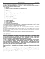
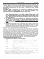
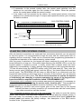
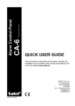
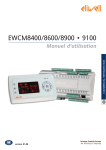
Description of terminals:
TMP
– anti-tampering
contact terminals
COM
– ground
DTA, CLK – keypad data bus
KPD
– power
supply
input (+12V)
ANTI-TAMPERING
CONTACT
BUZZER
Wire connections
TERMINALS
FOR WIRES
KEYPAD
CONTROL PANEL
KPD
KPD
DTA
DTA
CLK
CLK
COM
COM
TMP
Anti-tampering contact
terminals
TMP
TMP TMP COM DTA CLK KPD
Figure 1. CA-5 KLED-M keypad board.
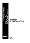
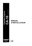
TMP TMP COM
TMPTMPCOM
KPD CLK DTA
KPD CLK DTA
TERMINALS
FOR WIRES
ANTI-TAMPERING
CONTACT
BUZZER
Figure 2. CA-5 KLED-S keypad board.
6
Alarm Control Panel
CA-5 SATEL
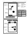
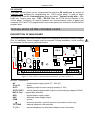
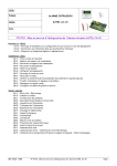
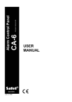
LCD-S (LCD-L) KEYPAD
The LCD-S (LCD-L) keypad works in conjunction with the CA-5 panels having software in
version 1.03 or later. It performs identical functions as the LED keypad. The liquid-crystal
display (2x16 characters) facilitates the system communication with the user and the
installer.
The LCD-S (LCD-L) keypad can be connected in parallel with the LED type keypads, or
with other LCD keypads. There are available two version of LCD keypads (CA-5 KLCD-L
and CA-5 KLCD-S) that differ in the dimension and the size of display.
COM CLK DTA KPD
ANTI-TAMPERING
CONTACT
TMP TMP
BUZZER
TERMINALS
FOR WIRES
Figure 3. CA-5 KLCD-S keypad board.
MONITORING
The CA-5 control panel can transmit information on the system status to a monitoring
station to one or two telephone numbers in various transmission formats.
The control panel will dial the second number of the station when the first number is
busy or the station does not confirm reception of the code. Irrespective of which
number is reached by the control panel, all events are transmitted.
It is possible to send information on the events concerning arming/disarming, zones
(alarms, tampering), as well as system events. Information can be sent to the station in
one of the fifteen transmission formats (including the Contact ID).
Owing to analysis of the commutation signals, the CA-5 control panel controls the process
of establishing connection with the station, which in case of high occupancy of the line
considerably reduces the time between occurrence of the event and sending the
information to the monitoring station. Repeated dialing attempts are made immediately on
discovering the busy signal, as a result of which the connection is established many times
faster than through the devices which wait for a specific signal during a pre-determined
time and only repeat the dialing attempt on discovering that the signal has not occurred.
Installation Guide
7
MONITORING – PERSONAL NOTIFICATION
The CA-5 panel monitoring function can be used for telephone notification of events taking
place in the security system (e.g. alarm or AC power failure). Short audible signals,
characteristic of transferring data to the monitoring station, will be heard in the telephone
handset.
In order to initiate telephone messaging by means of audible signals, the alarm control
panel must be programmed as follows:
1. Enter the control panel service mode.
2. Call in the FS-76 function and delete all the monitoring codes.
3. Using the FS-52 & FS-53 functions, program the telephone numbers to which the
audible information on events is to be sent. If the first number is busy, the control
panel will dial the second number.
4. Select the "0 no handshake" data transmission format in the FS-54 & FS-55
functions („13: Ademco Slow without confirmations”).
5. By means of the FS-56 function, set any four-character control panel identifier, e.g.
1111.
6. Assign codes to the events which are to be reported by by the control panel, e.g.
using the FS-57 function program the zone alarm codes.
7. Enable monitoring – FS-10 Option 1.
REMOTE PROGRAMMING - DOWNLOADING
In order to facilitate its programming, the CA-5 control panel has been equipped with
a DOWNLOADING feature, which enables a computer to be used for programming and
control of the security system. The programming may be effected directly through the
control panel RS-232 port (with TTL standard signals) or by means of a modem through
the telephone line terminals TIP and RING.
MODEM
Interfacing with the computer by means of the modem can be performed in two ways:
either in the remote mode (by means of the telephone cable network), or in the local mode.
In both cases the computer must be equipped with a modem.
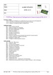
The local mode of programming can be entered by connecting the modem directly to the
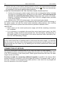
properly polarized TIP and RING telephone terminals of the control panel (see Figure 3).
The telephone line must be disconnected from the control panel.
CA-5 CONTROL PANEL
AC AC
∼18V + OUT1- OUT2 OUT3 AUX KPD DTA CLK COM Z1 Z2 COM Z3
AUX=+12V)
Z4 COM Z5
TIP RING T-1 R-1
To modem
Resistor 220Ω
Figure 4. Polarization of telephone line terminals in order to activate local communication
with the computer.
NOTE: Some modems require a capacitor (of at least 1µF) to be connected in the circuit
to separate the constant voltage polarizing the control panel telephone input.
8
Alarm Control Panel
CA-5 SATEL
Having initialized the modem in the DLOAD10 program (see Section „STARTING THE
CONTROL PANEL”) and having selected the CONNECT (locally) command, activate the
FS 77 service function in the control panel. When the communication is established,
download the control panel data and then proceed to download the events, program
parameters, etc.
The remote mode of programming can be reached by establishing the telephone
connection between the service computer and the control panel. Initialization of the
communication through the telephone line is possible in three modes:
1. The computer calls the alarm control panel, which, having answered the call,
exchanges communication passwords with the computer. If they are correct, the
control panel confirms reception of the remote programming order, hangs up and
calls the computer back to the number pre-programmed in the control panel. Before
calling back, the control panel notifies the monitoring station on starting the
programming process.
2. The computer calls the control panel and, after handshaking, the control panel
proceeds directly to data exchange. This simplified mode of establishing connection
can be reached, when no computer telephone number is entered on the control
panel. The monitoring station will be notified after communication with the computer
is ended.
3. Establishing communication on the control panel side by means of the 0 function
called by the master user or the service. Having called the function, the control
panel dials the computer telephone number pre-programmed with the FS 4 service
function and, after completion of the programming, notifies the monitoring station.
Initialization of the connection by the computer can be disabled.
In order to reduce the telephone connection costs, the transmission can be repeatedly
suspended. In case of a new connection, the control panel does not inform the monitoring
station of the remote programming, as this is only done before the first call-back. Instead,
after receiving the communication termination command, information on completion of the
remote programming is sent to the station. After suspending communication on the
computer side, the control panel is waiting four hours for a call, even when the automatic
call answering function is disabled. If the communication is not terminated with the “end”
but with the “suspend” command, the information on terminating the communication is
registered in the event memory and, after four hours, sent to the monitoring station.
Communication with the computer requires:
• The following to be programmed in the control panel:
− FS 2:
control panel password (the identifier which allows the program to
recognize the security system).
− FS 3:
computer password (the identifier which allows the control panel to
recognize computer authorized for communication).
− FS 4:
computer telephone number (it is not necessary but provides
higher protection against unauthorized access by the telephone
line).
− FS 5:
number of rings before answer (where the communication is to be
initialized from the computer).
− FS 11 option 1: if the DWNL function is to be initialized from the outside (by the
service computer).
• Cable connection (telephone or local) of the control panel with the computer modem.
• Launching the DLOAD10 program and initializing the modem operation.
• Setting identical communication passwords, options and number of rings in the
security system with those pre-programmed in the control panel.
Installation Guide
9
RS-232 PORT
The alarm control panel can be programmed through the RS serial port by means of
a special cable designed for programming the CA-5 control panel. In order to begin
programming, enter the Communication menu and select →Connect locally with..., then
select the control panel type →CA5 – RS-232. Start the FS 78 service function in the
control panel. Conformity is required between the communication codes of panel and
computer (FS 2 and FS 3) programmed in the control panel and included in the DLOAD10
program data.
INSTALLATION OF THE CONTROL PANEL
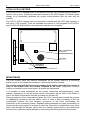
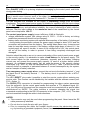
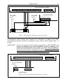
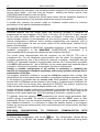
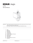
DESCRIPTION OF MAIN BOARD
The control panel main board contains electronic components sensitive to electric charges.
Prior to installation, these charges must be removed. During installation, avoid touching
any elements on the control panel main board.
F3
+KPD
T400mA
F1
F2
+OUT1
T3,15A
AC AC
∼18V + OUT1- OUT2 OUT3 AUX KPD DTA CLK COM Z1 Z2 COM Z3
RESET
DIALER
5W0.1ΩJ
CA-5
T3.15A
(BLACK)
(RED)
TO BATTERY
JP1
RS232
(TTL)
Z4 COM Z5
TIP RING T-1 R-1
Figure 5. View of CA-5 control panel main board, version CA5P V3.2
BOARD TERMINALS:
AC
- module power supply inputs (17...24V AC)
Z1 to Z5
- zones
OUT1
- signaling output (current-carrying capacity 3.15A)
OUT2, OUT3 - control panel programmable outputs (current-carrying capacity 50mA)
DATA, CLK - keypad bus terminals
KPD
- keypad power supply output
AUX
- detectors power supply output
COM
- ground
- protective terminal - ground (connect to protective circuit only)
TIP, RING
- external telephone line terminals
T-1, R-1
- internal telephone line terminals (telephone set connection)
10
Alarm Control Panel
CA-5 SATEL
The „DIALER” LED is lit up during telephone messaging by the control panel, and blinks
during pulse dialing.
Situated next to the LED is an adjustable resistor. Its setting should not be changed,
since it would cause incorrect work of the dialer (loss of the capability of dialing in the
DTMF system and monitoring in the „Ademco Ex” i „Contact ID” formats).
The AC terminals are intended for the supply of alternating voltage from the mains
transformer. The control panel power supply is suitable for operation with the input voltage
of 17...24V AC. The control panel is fitted with an advanced pulse-type power supply of
high energy efficiency and operational reliability, the correct functioning of which requires,
however, that the input voltage at the maximum load of the transformer by the control
panel never drop below 16V AC.
The control panel power supply (current efficiency 1,2A) is fitted with:
voltage stabilization system (the voltage value of 13.6V – 13.8V is factory set during
production process and should not be changed);
battery status monitoring system with optional disconnection of the battery if discharged
- during testing the processor reduces the power supply voltage to about 10.5V and the
consumers are powered from the battery. The testing takes place every 4 minutes and
lasts for less than twenty seconds. If the battery voltage drops down to about 11V, the
control panel will report a trouble. In case of the voltage fall to 9.5V, the control panel
will cut off the battery in order to prevent it from being completely discharged and
damaged.
Attention should be paid so as not to cause overloading of the control panel power supply
in the security system. It is advisable to make a load balance for the power supply. The
total current inputs for the consumers (detectors, keypads) and the battery charging
current may not exceed the power supply capacity. In case of a higher electric power
demand, an additional power supply can be used for some of the security system
consumers (e.g.: APS -15, APS-30 manufactured by SATEL). Table 1 (at the end of this
manual) shows an example of estimated balance of current consumption by the system,
and an example of battery selection.
Two emergency power supply wires: connect the red one to the battery terminal “+” and
the black one to the battery terminal “-“. The battery circuit is protected with a WTA-T
3.15A fuse .
The JP1 „RESET” pins make it possible to start the service mode without entering any
service code. This function can be disabled by the installer with the software means (see:
FS 9 - Option 1).
The RS232 (TTL) connector is intended for programming the alarm system parameters
from the computer. As the control panel sends and receives a TTL standard signal (0V,
+5V), the RS ports of the panel and the computer must be connected with a special cable
manufactured by SATEL. The cable includes a converter changing the signal into
a standard corresponding to the RS-232 connector in the computer (-12V, +12V). The data
can be transmitted through the cable in both directions.
NOTES:
• The connector may only be used when programming the panel. Never leave the RS
cable permanently attached.
• Do not short or touch the pins with your fingers.
• Prior to connecting the cable, the installer should remove the electrostatic charge,
e.g. by touching a grounded equipment (faucet, heater, etc.). with the top of his hand.
Installation Guide
11
• It is recommended that the cable be connected first to the control panel connector,
and then to the computer connector.
BEND ASIDE
BEND ASIDE
The CA-5 main board enables an electric shock protection circuit (grounding) to be
connected. The protective cable terminal is designated by the
symbol.
The „neutral” wire of the 230V AC mains supply must not be connected to it. If the site has
no separate electric shock protection circuit, this terminal must be left free.
The telephone line must be a four-wire line so that the control panel can be connected
before the other devices (telephone, telefax, etc.).
CAUTION! Do not send telephone signals and alarm system signals by one multicore
cable. This may result in a damage to the system in case of a high-voltage
punch-through from the telephone line.
The CA-5 control panel should be installed in enclosed spaces with a normal humidity of
air. It can be mounted in the CA-6 OBU housing with a transformer
designed for operation with the control panel power supply, which
permits installation of a battery with 7Ah capacity. Before the housing is
secured to the base, it is necessary to mount inside the housing plastic
distance plugs, which are intended for subsequent installation of the
main board. In case the plugs tend to slip out, the catches fixing the plug
in the housing need to be slightly bent aside (Figure 6). When inserting
the plug press in the central part of the head firmly in so that it is
blocked in the housing.
It is advisable to make sure that the plug, when pressed, does not slip
out from the opening. During installation of the housing, be careful so as
PRESS IN
not to damage the wires which will be passed through the hole in its
Figure 6.
back panel.
When the housing is secured, you can install the control panel main board and proceed to
making the connections.
CONNECTION OF POWER SUPPLY
It is required that the control panel be permanently connected to the mains power.
Therefore, prior to starting the work on the system cabling, make yourself familiar with the
electrical installation of the site and select a circuit which is permanently alive to power the
control panel. The circuit is to be protected with an appropriate fuse.
CAUTION!
The control panel is power supplied from the 230V AC mains. Carelessness or
wrong connection may result in electric shock and pose a threat to life!
Therefore, exercise particular caution when connecting the control panel. In the
process of installation and connection of the control panel, the cable to be used for
mains supply must not be alive!
Description of electrical connections to the CA-4/5/6 OBU housing.
The AC power supply unit encased in the plastic box is fully electrically isolated from the
metal housing.
Connect the 230V alternating voltage leads to the transformer terminals marked
"AC 230V".
Connect the output voltage wires of the transformer secondary winding to the "AC~18V"
terminals on the control panel main board.
12
Alarm Control Panel
CA-5 SATEL
Connect the wire of the electric shock protection circuit to the terminal block provided
next to the transformer and marked with the ground symbol
. This circuit should also
be connected to the control panel protective terminal.
STARTING PROCEDURES FOR THE CONTROL PANEL POWER SUPPLY.
1. Connect the emergency power supply wires to the corresponding battery terminals
(the red one to the battery plus, the black one to the minus). The control panel will
not start on connecting the battery alone (without the mains power connected),
however, it will keep on working in case of the ~230V AC voltage trouble, provided
it was started before.
2. Switch on the ~230V AC mains supply – the control panel gets started.
Connection of the power supplies in the prescribed order will permit correct functioning of
the power supply unit and the control panel electronic safety devices, thus avoiding
damage to the security system elements caused by possible installation faults.
IMPORTANT:
• Never switch on the control panel power supply until all the remaining connections
are completed.
• If it is necessary to completely disconnect the control panel power supply, the 230V
alternating voltage should be disconnected first, then the battery. Re-connection of
the power supply is to be performed in the above mentioned order (the battery first,
then the 230V alternating voltage).
CAUTION!
As the control panel has no isolating switch to disconnect the mains supply, it is important
that the owner or the user of the security system be informed on how the system is to be
disconnected from the mains (e.g. by indicating the fuse which protects the control panel
supply circuit).
CONNECTION OF KEYPAD
The CA-5 control panel interfaces with SATEL made LED and LCD type keypads.
The keypad should be connected to the system with a four-wire line, using the COM, KPD,
DTA, CLK connectors on the control panel. Where typical conductors are used, the cable
length can be up to 200m.
Provision is made for connecting additional keypads (in parallel to the others). Each
keypad should be connected to the control panel by means of a separate cable. If this is
the case, activation of the programming mode (service or user one) from any keypad will
block the operation of the other keypads.
Installation Guide
13
CA-5 CONTROL PANEL
AC AC
∼18V + OUT1- OUT2 OUT3 AUX KPD DTA CLK COM Z1 Z2 COM Z3
TO
ANTITAMPERING
CIRCUIT
Z4 COM Z5
TO
ANTITAMPERING
CIRCUIT
TMPTMPCOM
TIP RING T-1 R-1
LED-M KEYPAD
TMP TMP COM DTA CLK KPD
KPD CLK DTA
LED-S KEYPAD
Figure 7. LED keypads connection to the control panel.
The anti-tampering contact (NC) of the keypad should be connected with the system
anti-tampering circuit. Where two keypads are connected in parallel, the (TMP)
anti-tampering contacts should be connected in series, and the other keypad wires - in
parallel.
IMPORTANT: If one of the system zones has been programmed as „24H TAMPER” and
used for protection of the system elements against tampering, thus
creating an anti-tampering circuit, violation of such a zone will trigger no
alarm if the control panel is in the service mode. If the control panel gives
an alarm at the moment of exiting the service mode, it can mean violation
of the anti-tampering line (opening of one of the contacts).
CA-5 CONTROL PANEL
AC AC
∼18V + OUT1- OUT2 OUT3 AUX KPD DTA CLK COM Z1 Z2 COM Z3
Z4 COM Z5
TIP RING T-1 R-1
TO ANTI-TAMPERING
CIRCUIT
TMP TMP
KPD DTA CLK COM
LCD KEYPAD
Figure 8. Connection of LCD keypad to the CA-5 panel.
14
Alarm Control Panel
CA-5 SATEL
CONNECTION OF DETECTORS
Z5 – programmed as „24H TAMPER”
CA-5 CONTROL PANEL
AC AC
∼18V + OUT1- OUT2 OUT3 AUX KPD DTA CLK COM Z1 Z2 COM Z3
2,2kΩ
2x1,1kΩ
Z4 COM Z5
TIP RING T-1 R-1
2,2kΩ
NC NC TMP TMP COM 12V
GND TMP TMP C NO +12V
NC NC TMP TMP COM 12V
NC NC TMP TMP COM 12V
2EOL/NO
or
2EOL/NC
(AQUA,
AQUARING,
INDIGO)
EOL
for
NO
EOL
for
NC
(AQUA,
AQUARING,
INDIGO)
NO
or
NC
(AQUA,
AQUARING,
INDIGO)
Figure 9. Example of connecting 4 detectors in various configurations
(with Z5 anti-tampering circuit).
NOTE: The real system anti-tampering circuit should also include the anti-tampering
contacts of keypad, signaling devices, control panel housing, etc.
The circuit connected to the one-parameter configured zone (EOL) is to be closed with
a 2,2 kΩ resistor. In case of two-parameter zone, the detector output is to be closed with
two 1,1 kΩ resistors. This type zones (2EOL) allow the control panel to simultaneously
monitor the status of detector and its anti-tampering contact (see Figure 9).
The NO and NC detectors in two-parameter configuration can be connected in the
identical way, it is only important to indicate to the control panel what type of detector is
connected to the zone (2EOL/NO or 2EOL/NC). The same is the case with the detectors
having no parameter.
The AUX output is intended to be used for powering the detectors. Separation of the
detector power supply ground and the input line ground permits eliminating the adverse
effect of the wiring resistance. Assuming that the cable is not very long and that it has just
one detector connected, it is possible to make the installation simpler by leading the power
supply ground wire (GND) and the signal ground wire in one conductor.
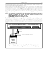
CONNECTION OF SIGNALING DEVICES
Where signaling devices are used that give alarm when power supply is switched on, the
"+ " of signaling device power supply should be connected to the control panel +OUT1
Installation Guide
15
terminal, and the signaling device "ground" - to the control panel –OUT1 terminal. In this
mode, one independent signaling device can be set.
Where signaling devices with internal battery of their own are employed, the +OUT1 output
should be used to power the signaling devices, the signaling device ground should be
connected to the control panel COM terminal, and the triggering signals should be
provided by the –OUT1 output and the OUT2 and/or OUT3 low-current outputs. Triggering
alarm in the signaling devices must be effected with 0V voltage (by shorting the control
input).
NOTE: The polarization of output OUT1 can be reversed (FS 9 option 4) and then it
operates in a different way than the low-current outputs OUT2 and OUT3 do
active state: terminal -OUT1 cut off, no COM
normal state: terminal -OUT1 shorted to COM).
The OUT2 and OUT3 outputs can be utilized to control the relays switching on any
signaling devices or other equipment. The relays can be directly connected to the outputs,
as shown in Figure 10 which presents connection of the SPL-2010 visual signaling device.
It should be borne in mind that these outputs can be loaded with a maximum current of
50mA.
OUT2 – programmed as „Alarm to be cleared”
AC AC
+ OUT1- OUT2 OUT3 AUX KPD DTA CLK COM Z1 Z2 COM Z3
∼18V
CA-5 CONTROL PANEL
Z4 COM Z5
TIP RING T-1 R-1
RELAY
TO ANTI-TAMPERING CIRCUIT
+ SO -
+ SA -
SAB
Signaling
device
SPL-2010
Figure 10. Example of connecting the SATEL SPL –2010 signaling device
(OUT1 – audible signaling; OUT2 – relay controlled visual signaling).
16
Alarm Control Panel
OUT2 – programmed as „Alarm to be cleared”
AC AC
∼18V + OUT1- OUT2 OUT3 AUX KPD DTA CLK COM Z1
CA-5 SATEL
CA-5 CONTROL PANEL
Z2 COM Z3 Z4 COM Z5
TIP RING T-1 R-1
Triggering the audible and visual alarms
in the signaling device when the outputs
–OUT1 and OUT2 are shorted to ground.
R=2,2kΩ
R
R
TO ANTI-TAMPERING CIRCUIT
GND+12V STO STA SAB SAB
SPLZ-1011
Signaling device
To ensure proper operation of the signaling
device, it is necessary to connect the bias
resistors to STA and STO inputs in the
signaling device.
Figure 11. Example of connecting the SATEL SPLZ–1011 signaling device
(-OUT1 – audible signaling; OUT2 – visual signaling).
CONNECTION OF TELEPHONE LINE
If the security system utilizes the control panel telephone communicator (for remote
programming or monitoring), it is necessary to connect telephone line to the control panel.
It should be connected to a connector situated on the right side of the printed board. In
order to ensure proper operation of the dialer, the control panel must be directly
connected to the line (connectors designated as TIP and RING), and any other devices
(telephone, telefax) - after the control panel (connectors designated as T-1 and R-1). Such
a connection will make it possible for the control panel to fully engage the line for the time
of calling, which prevents the monitoring function from being blocked by lifting the handset.
Additionally, the telephones connected after the control panel do not signal the dialing by
the control panel.
CAUTION!
• Telephone terminals of the panel should be connected to PSTN lines only.
Connecting to ISDN lines may lead to damage of the equipment.
• System installer should give the necessary information on the way of connection with
telephone network to system owner.
TELEPHONE LINE SWITCH
The control panel has been fitted with the telephone line switch function, which improves
the efficiency of monitoring. The function is served by the type 10 „Telephone line switch”
output. Where two telephone lines are available at the site, this output can directly control
the relay to switch over the telephone line connected to the TIP and RING terminals. The
output gets activated if problems occur with sending the code to both telephone numbers
of the monitoring station.
The function works in the following way:
• The control panel dials the first number of the monitoring station in order to send the
event code. If it fails to send the code, the other number of the station is dialed.
Installation Guide
17
• If connection to the second number fails, the control panel switches over the
telephone line and dials again the first number of the station. When the problem
recurs, the control panel redials the second number.
• If the code is still not received by the station, the control panel returns to the first
telephone line (deactivates the type 10 output) and repeats the whole cycle of dialing
the station numbers.
OUT2 – programmed as ”Telephone line switch”
AC AC
∼18V + OUT1- OUT2 OUT3 AUX KPD DTA CLK COM Z1 Z2 COM Z3
CA-5 CONTROL PANEL
Z4 COM Z5
TIP RING T-1 R-1
LINE 1
LINE 2
TELEPHONE
Figure 12. Connection of two telephone lines to the control.
STARTING THE CONTROL PANEL
After all electrical connections are made and their correctness checked, you can proceed
to start the system. It is recommended to begin the work with the control panel with no
signaling devices connected. These can be connected after programming parameters is
completed and operation of the realized security system tested.
After the power is switched on, the keypad will report readiness for work with four short
beeps followed by a long one. If the panel starts alarming (the ALARM LED is on and the
keypad makes a continuous sound), it usually means that a tamper alarm has been
triggered by incompatibility of factory settings with parameters of the connected detectors.
To clear the alarm enter the MASTER access code [1234] and press [#]. Then, enter the
factory service code [12345] and accept it with the [#] key - the control panel will enter the
service mode. The PROGRAM LED will come on and will be lit up continuously and the
keypad will start emitting a short beep every 3 seconds. At this moment, you can proceed
to programming the control panel. The list of service functions as well as the method
of introducing and changing of system parameters by means of the keypad have
been described in a separate instruction called “PROGRAMMING LIST".
If the service code is unknown (as its contents was previously changed), it is necessary to
carry out the procedure of entering the service mode „from the pins”. This procedure is
presented together with the description of service functions in the „Programming List”.
NOTE: Blinking of all LEDs and sound signals given at the same time by the keypad
indicate that there is a faulty connection (no communication with the control panel)
– the cable connections must be checked.
If the suggested procedure turns out to be unsuccessful, the option to enter the service
mode „from the pins” must have been disabled in the control panel by software means. If
this is the case, it is necessary to carry out another procedure which would unblock the
control panel and restore the factory settings - see description of the FS 9 service
function in the „Programming List”.
18
Alarm Control Panel
CA-5 SATEL
After completing the procedure, exit the service mode using the FS 0 function and call the
service mode again - this time from the keypad - entering the factory access code
[1][2][3][4][5] and accepting it with the [#] key.
Re-entering the service mode by the control panel means that the equipment operation is
correct and programming of all necessary parameters may be commenced.
A trouble with entering the service mode by hardware method points to incorrect
performance of the above mentioned procedures.
DLOAD10 PROGRAM
Delivered together with the control panel, the DLOAD10 program is designed for
programming the control panels: CA-5, CA-6, CA-6 plus, CA-10 and CA-10 plus, as well
as the radio controllers RX2K and RX4K from a computer. Furthermore, the program
makes possible creation of documentation for the security systems, sets of settings for
various configurations ("patterns" which facilitate programming new systems), sets of
events for each system, as well as remote control of the control panel, identical as by
means of the keypads.
The program is designed for IBM PC/AT compatible computers. It works in any computer
hardware configuration in the WINDOWS (9x/ME/2000/XP) environment. It is
recommended that the program be installed on the computer hard drive.
The control panel communicates with the computer via the RS-232 (TTL) link or
a telephone line. For the telephone communication with the panel, the program uses
a modem controlled by one of the COM ports (external or internal), compatible with the
HAYES "AT Command" standard. Communication with the CA-5 control panel is possible
in the BELL 103 standard (at rate of 300 Bps). As the control panel only transmits data at
a speed of 300 bauds, the modem must support this rate of transmission.
Usually, a suitable configuration of the modem is necessary i.e. disabling the
function of transmission standard negotiation and forcing operation with the rate of
transmission of 300 Bps.
The program installation consists in running the setup.exe program from a floppy disk
delivered with the control panel. After installation, the program should be launched. Access
to the program is protected with an access code. After installation of the program, the
access code is: 1234 and can be changed in any string of 16 alphanumeric characters. As
long as the code has its factory form, pressing the „ENTER” key (without entering any
code) will start the program with the default access code (1234).
Having started the program, perform the configuration and initialize the RS-232 port, or the
modem, by means of which the control panel will be programmed. The further step can be
selection of the control panel type CA-5 and starting of connection (remote or local).
To facilitate using the program and programming the control panel parameters itself,
a HELP system is provided. The system is accessible from the „HELP” menu or, after
pressing the F1 key, from the computer keyboard. In order to get an immediate access to
more detailed information, it is necessary to select the desired element in the program
window (by moving the mouse pointer onto it and clicking the left mouse button), and then
press the F1 key.
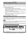
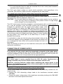
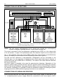
PROGRAM
CONFIGURATION
THE CONTROL PANEL
TO
ESTABLISH
COMMUNICATION
WITH
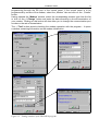
In order to start configuration, click on the
icon - the „Configuration” window will be
opened. The "Port RS-232" tab enables the port number to be selected during direct
Installation Guide
19
programming through the RS port of the control panel. If the control panel is to be
programmed by means of the modem, select the „Modem” tab and click on the „Details”
button.
Having opened the „Modem” window, select the corresponding modem type from the list
or click on the „! Change” button and enter the data according to the documentation of
your modem. Clicking on this button will also allow you to change the communication port
number or the rate of transmission.
The „9Test” button permits checking the modem operation with the program – it opens
a window containing information on the modem initialization.
Figure 13. – Dialog windows of the DLOAD10 program.
20
Alarm Control Panel
CA-5 SATEL
In order to start communication through the RS port or modem, you should follow the
procedures set forth in the section „REMOTE PROGRAMMING – DOWNLOADING”.
After correct initialization of the operation, close the configuration windows and click on the
icon (or select the „MODEM” command from the „COMMUNICATION” menu). The
program will open a window enabling a connection to be made and will prompt further
procedures.
The control panel type is recognized automatically after establishing connection, or it can
be selected through the „File” menu.
Calling the downloading function with the communication established (the
icon), can
speed up the subsequent process of uploading changes made to the panel software.
DEFAULT SETTINGS
The control panel is preprogrammed for work in the following configuration:
• service code: 12345,
• master code: 1234,
• panel communication code – 3736353433323130,
• computer communication code – 3031323334353637,
• number of rings before answer – 2,
• exit delay - 30 seconds,
• keypad alarm duration – 30 seconds,
• entry delay - 30 seconds (for zone 1),
• zone 1 (Z1) - entry/exit line, EOL, violation will generate chime signal in the
keypad,
• zones 2 to 4 (Z2 ... Z4), - instant, EOL, may not be violated during arming,
• zone 5 (Z5) – 24h tamper line, EOL,
• sensitivity of all zones - 480 ms,
• OUT1 output - audible alarm (duration – 60 seconds, shorted to ground during
alarm, assigned to all zones),
• OUT2 output - visual alarm (duration - until cleared),
• OUT3 output - failure indicator for AC supply, battery or telephone,
• monitoring disabled,
• downloading disabled.
The above settings can be restored by using the FS 74 service function - "restart settings"
(except for the service and user access codes, which are restored by the FS 75 function –
"restart codes").
Installation Guide
21
TECHNICAL DATA
Main board supply voltage..................................................................................AC 17...24V
Main board current consumption ..................................................................................70mA
Keypad current consumption min./max. ......................................................... 35mA / 85mA
Power supply rated voltage ..........................................................................DC 13.6...13.8V
Total capacity of power supply .......................................................................................1.2A
Standby power supply (recommended) ....................................................... battery 12V/7Ah
Battery charging current .............................................................................................350mA
Battery protection ............................................................................................... 3.15A delay
Battery cut-off voltage.......................................................................................... 9.5V ±0.3V
Number of programmable zones ......................................................................................... 5
Number of programmable outputs ....................................................................................... 2
Current-carrying capacity of OUT1alarm output ...........................................................3.15A
Current-carrying capacity of OUT2 and OUT3 outputs.................................................50mA
Control panel operation temperature range ............................................................... 0÷55ºC
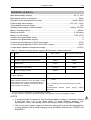
Table 1. Example of panel power supply load estimation / battery selection.
No. Loads
Max current
Mean current consumption
1
Main board CA-5
70mA
70mA
2
Keypad + output AUX and 5 detectors*
400mA
200mA
3
Output OUT1
3.15A **
0.5A
4
Outputs OUT 2 and OUT3
2 x 50mA
50mA
5
Battery charging current
350mA
-
Total max current consumption by the system with
no alarm signaling
∑I = 70mA+400mA+100mA+350mA =920mA
∑AMax= 1.25x(0.07x12+0.4x12+3.15x0.25+0.1x0.25)
≈ 8.1Ah
Battery selection based on max. and mean current
consumption by the system, assumed duration of
∑AAv= 1.25x(0.07x12+0.,2x12+0.5x0.25+0.1x0.25)
power trouble 12h, assumed 1 alarm with 15 min
≈ 4.2Ah
(0.25h) duration of signaling
Recommended standby power supply: battery
12V/7.5Ah
* Assumed current consumption by a single detector 20mA.
** In case, where the capacity of the power supply is exceeded, the current is supplied by battery.
NOTES:
• It is impermissible to connect a fully discharged battery (voltage on terminals without
a load less than 11V) to the alarm panel. To avoid hardware damage, fully
discharged or never used battery should be charged initially using proper charger.
• The control panel power supply unit has been designed for work with lead batteries
or other batteries with a similar charging curve (European Directives 91/157/EEC and
83/86/EEC)
ATTENTION !
An efficient security system does not prevent burglary, assault or fire from happening,
however it diminishes the risk that such a situation will cause no alarm or notification.
Therefore, the SATEL Company recommends that operation of the whole security system
be regularly tested.
SATEL sp. z o.o.
ul. Schuberta 79
80-172 Gdańsk
POLAND
Tel. +48 58 320 94 00
[email protected]
www.satel.pl