1
285
Service.
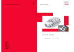
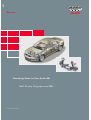
Running Gear in the Audi A8
Self Study Programme 285
For internal use only
The requirements to be met by the new A8
running gear were highly diverse and thus led
to a whole series of conflicting technical
aims.
The remedy to these complex problems was
found in the introduction of new concepts
alongside progressive improvements to
existing ideas and the close coordination of
all sub-systems.
This approach meant that it was possible to
raise the high level of active road safety of the
predecessor model still further and thus to
again set new standards in the luxury
segment.
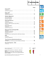
Contents
Page
Front Axle
Summary . . . . . . . . . . . . . . . . . . . . . . . . . . . . . . . . . . . . . . . . . . . . . . . . . . . . . . . . . . . .4
System components . . . . . . . . . . . . . . . . . . . . . . . . . . . . . . . . . . . . . . . . . . . . . . . . . . .5
Rear Axle
Summary . . . . . . . . . . . . . . . . . . . . . . . . . . . . . . . . . . . . . . . . . . . . . . . . . . . . . . . . . . .10
System components . . . . . . . . . . . . . . . . . . . . . . . . . . . . . . . . . . . . . . . . . . . . . . . . . .12
Wheel Alignment
General procedure. . . . . . . . . . . . . . . . . . . . . . . . . . . . . . . . . . . . . . . . . . . . . . . . . . . .14
Front axle settings . . . . . . . . . . . . . . . . . . . . . . . . . . . . . . . . . . . . . . . . . . . . . . . . . . . .14
Rear axle settings . . . . . . . . . . . . . . . . . . . . . . . . . . . . . . . . . . . . . . . . . . . . . . . . . . . .15
Steering System
Summary . . . . . . . . . . . . . . . . . . . . . . . . . . . . . . . . . . . . . . . . . . . . . . . . . . . . . . . . . . .16
System components . . . . . . . . . . . . . . . . . . . . . . . . . . . . . . . . . . . . . . . . . . . . . . . . . .16
Electrical steering column lock (ESCL) . . . . . . . . . . . . . . . . . . . . . . . . . . . . . . . . . . .28
Summary . . . . . . . . . . . . . . . . . . . . . . . . . . . . . . . . . . . . . . . . . . . . . . . . . . . . . . . . . . .28
Brake System
Summary . . . . . . . . . . . . . . . . . . . . . . . . . . . . . . . . . . . . . . . . . . . . . . . . . . . . . . . . . . .30
System components . . . . . . . . . . . . . . . . . . . . . . . . . . . . . . . . . . . . . . . . . . . . . . . . . .31
Electromech. Parking Brake
Summary . . . . . . . . . . . . . . . . . . . . . . . . . . . . . . . . . . . . . . . . . . . . . . . . . . . . . . . . . . .34
Operation and display. . . . . . . . . . . . . . . . . . . . . . . . . . . . . . . . . . . . . . . . . . . . . . . . .35
System components . . . . . . . . . . . . . . . . . . . . . . . . . . . . . . . . . . . . . . . . . . . . . . . . . .36
Functions . . . . . . . . . . . . . . . . . . . . . . . . . . . . . . . . . . . . . . . . . . . . . . . . . . . . . . . . . . .40
Electromechanical parking brake CAN data exchange . . . . . . . . . . . . . . . . . . . . . .45
ESP
Summary . . . . . . . . . . . . . . . . . . . . . . . . . . . . . . . . . . . . . . . . . . . . . . . . . . . . . . . . . . .46
System components . . . . . . . . . . . . . . . . . . . . . . . . . . . . . . . . . . . . . . . . . . . . . . . . . .48
Tyre Pressure Monitoring System
Summary . . . . . . . . . . . . . . . . . . . . . . . . . . . . . . . . . . . . . . . . . . . . . . . . . . . . . . . . . . .54
Tyre pressure monitoring system CAN data exchange . . . . . . . . . . . . . . . . . . . . . .56
Run Flat System - PAX
Summary . . . . . . . . . . . . . . . . . . . . . . . . . . . . . . . . . . . . . . . . . . . . . . . . . . . . . . . . . . .58
The Self Study Programme contains information on design
features and functions.
New!
Attention!
Note!
The Self Study Programme is not intended as a Workshop
Manual.
Values given are only intended to help explain the subject
matter and relate to the software version applicable when the
SSP was compiled.
Use should always be made of the latest technical publications
when performing maintenance and repair work.
3
Front Axle
Summary
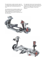
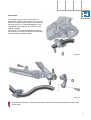
The new A8 is fitted with the familiar four-link
front axle (refer to SSP 161).
All axle components are new on account of
the geometric and kinematic modifications as
compared to the predecessor model, as well
as the air suspension and the weight
reductions achieved.
Wherever technically feasible, use is made of
identical components for the VW Phaeton and
Audi A8.
A significant new feature is the air
suspension in combination with
electronically controlled dampers (refer to
SSP 292).
Mounting bracket
Upper link
Wheel bearing
housing
Suspension/damper strut
Wheel
bearing
Wheel
hub
Subframe
Anti-roll bar
Subframe bushes (4x)
Track control link
Anti-roll bar
connecting link
Guide link
VW Phaeton / Audi A8 identical components
285_001
4
System components
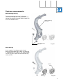
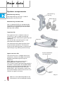
Wheel bearing housing
The wheel bearing housing is a forged
aluminium component. The guide and track
control link mounts take the form of press-fit
zinc-iron coated bushes.
Wheel bearing
housing
Link mounting
bushes
285_002
Wheel bearing
Use is made of a 2nd generation wheel
bearing (flange bearing). A Ø 92 mm bearing
is employed for all engines. The wheel speed
sensor ring forms part of the wheel bearing
(refer to ESP).
Wheel
hub
Wheel
bearing
285_076
5
Front Axle
Mounting bracket
The mounting bracket is made of Poral cast
aluminium. It is bolted to the body and
designed to support the upper transverse
links and the spring/damper unit.
Pay attention to body bolted joint
tightening sequence!
(refer to current Workshop Manual).
285_003
Links
The upper and lower links are made of forged
aluminium. To minimise road noise and tyre
vibration, the guide link is connected to the
subframe by means of a large hydraulically
cushioned bush.
Heed installation positioning!
(refer to current Workshop Manual).
285_004
6
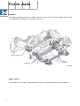
Spring/damper unit
Details of the design and operation of the air suspension system components can be found in
SSP 292.
285_077
7
Front Axle
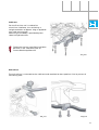
Subframe
The subframe takes the form of a welded stainless steel shell. To increase rigidity, the U-shape
is completed by a bolted cross member at the rear.
Engine support
Subframe
Cross
member
285_005
Engine support
A new feature is an engine support bolted to the front attachment points of the subframe.
8
Anti-roll bar
For weight-saving reasons, the vehicle is
fitted with a tubular anti-roll bar. The anti-roll
bar joins the two track control links by way of
connecting links. A new development is the
method of mounting the anti-roll bar at the
engine support.
The bushes are vulcanised onto the tubular
bar and can no longer be replaced separately
when performing service work.
285_006
285_007
All mounting elements are to be attached in basic level setting ("Automatic" mode, refer
to SSP 292).
9
Rear Axle
Summary
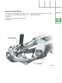
The rear axle is a more advanced version of
the familiar A8' 02 trapezium-link axle.
All axle components are new on account of
the geometric and kinematic modifications as
compared to the predecessor model, as well
as the air suspension and the weight
reductions achieved.
Wherever technically feasible, use is made of
identical components for the VW Phaeton and
Audi A8.
Subframe
Upper transverse link
Anti-roll bar
connecting link
Trapezium link
Wheel
hub
Anti-roll bar
Wheel
bearing
Link
connecting rod
VW Phaeton / Audi A8 identical components
10
Track rod
285_008
Principal new features compared to A8 `02
– Use of air suspension in conjunction with
electronically controlled damping
– Aluminium subframe to help reduce
weight
– Joint arrangement of spring and damper
at upper transverse link
– Connection of anti-roll bar to trapezium
link
– Use of modified track rod to reduce
change in toe on compression and
extension of suspension
– Use of ball studs to connect wheel bearing
housing and track rod, thus reducing
secondary spring rate
– Use of slotted bonded rubber bushes in
upper transverse link and connection
between trapezium link and subframe
11
Rear Axle
System components
Wheel bearing
housing
Wheel bearing housing
The wheel bearing housing is made of
gravity die cast aluminium.
Wheel bearing
Wheel
hub
Wheel bearing and wheel hub
Use is made of a Ø 85 mm 2nd generation
wheel bearing (flange bearing). The wheel
speed sensor ring forms part of the wheel
bearing (refer to ESP).
285_009
Trapezium link
The trapezium link is made of sand cast
aluminium. It acts as lower connecting
element between wheel bearing housing and
subframe.
The anti-roll bar connecting link is now
attached to the trapezium link.
Split bush
The subframe mount takes the form of an
asymmetrically split bush. This helps to
enhance self-steering action in the event of
load changes (e.g. braking and cornering).
Upper transverse link
The transverse link is a forged aluminium
component. It forms the upper connection
between wheel bearing housing and
subframe.
Body support at the transverse link is
provided by the suspension strut.
This is the first time new mounting elements
have been used by Audi. The bonded rubber
bushes are axially slotted to enable them to
absorb great axial forces with minimum
deformation. They nevertheless retain their
torsional flexibility and the link can thus turn
without any great resistance.
285_010
Suspension/damper
strut attachment
Slotted
bush
285_011
Refer to current Workshop Manual for
information on Disassembly/Assembly.
12
Subframe
For the first time use is made of an
aluminium subframe, thus achieving a
weight reduction of approx. 9 kg as opposed
to a steel construction.
Mounting at the body is provided by four
identical hydro-bushes.
The bushes have a specified installation
position in the subframe (refer to
current Workshop Manual)!
285_012
Anti-roll bar
The anti-roll bar is mounted at the subframe and attached to the trapezium links by means of
connecting rods.
285_013
285_014
13
Wheel Alignment
General procedure
The basic principles of wheel alignment and adjustment have been retained.
Main changes over A8 `02
– The toe constant is now set in vehicle basic
position (B=1).
– Balancing out of front axle toe values
involves adjusting subframe together with
engine support.
– On vehicles with adaptive cruise control,
the distance sensor has to be checked/
adjusted after changing rear axle toe
values.
"Automatic" mode must be set shortly prior to wheel alignment.
Vehicle must be at a settled level at the start of wheel alignment.
For details, refer to wheel alignment computer user prompting.
Front axle settings
As in the past, individual toe values and the
toe change profile on suspension
compression/extension (= "toe-in curve") can
be set for the four-link front axle.
The camber values can be balanced out
between the right and left side of the axle.
This is achieved by moving the subframe
sideways together with the engine support
(for detailed information, refer to current
Workshop Manual).
285_078
14
Rear axle settings
The camber is set by means of an eccentric at
the transverse link/wheel bearing housing
bolted joint.
(For detailed information, refer to current
Workshop Manual).
The toe is set at the track rod/subframe
bolted joint.
Eccentric bolt for
setting camber
Eccentric bolt for
setting toe
285_079
15
Steering System
Summary
Customers can choose between mechanical and electrical steering column adjustment, as
well as between power steering and Servotronic.
Principal new features compared to A8 `02
– Electrical steering lock
– Servotronic II
– Spindle-driven electrical steering column
tilt adjustment
– Larger steering mechanism piston
diameter
– Rigid track rods
– More detent positions at steering column
splines
– Variable steering ratio
System components
Steering pump
Use is made for all petrol engines of the FP6
vane pump with a delivery volume of 15 cm3
per revolution. The maximum system
pressure is limited to 125 bar.
For all diesel engines, use is made of the FP4
vane pump
with a delivery volume of 11 cm3 per
revolution. The maximum system pressure is
again limited to 125 bar.
285_080
16
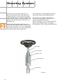
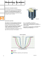
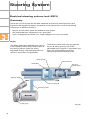
Steering mechanism
Design:
The rack and pinion steering mechanism essentially consists of a rack and pinion with
mounting elements, piston and rotary slide valve.
285_017
Principal differences compared to A8 `02
– Manufacturing the rack splines with
different modules and meshing angles
permits variable translation of steering
wheel movements into rack travel. This
variable ratio achieves a more direct
response with larger steering angles.
Rack travel per steering wheel turn [mm]
– The piston diameter was increased from
43 mm to 45 mm on account of the higher
axle load on vehicles fitted with the full
range of equipment.
– The rotary slide now has 10 grooves
instead of 6, thus increasing the number
of helices at the rotary slide. This produces
a larger cross-section for the flow of fluid
and lowers the sound level by reducing
flow noise.
Steering wheel angle
285_018
17
Steering System
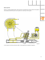
A torsion bar in the rotary slide valve is
directly connected to the steering column
shaft by way of a universal joint. The upper
end of the torsion bar is rigidly linked to the
rotary slide by means of a pin connection. The
lower end is pinned to the rack pinion and
pilot bushing.
Driver-induced steering motion causes a
force to act on the torsion bar. The torsion bar
is turned (= twisted) in a manner comparable
to anti-roll bar torsion at an axle subjected to
one-sided suspension compression.
The rotary slide is turned together with the
torsion bar relative to the pilot bushing.
This results in a change in the relative
positions of the grooves and bores in the
rotary slide and pilot bushing.
Specific fluid ducts can thus be opened and
others closed depending on the angular
offset between rotary slide and pilot bushing.
Torsion bar
Pin connection
Rotary slide
Pilot bushing
Rack pinion
285_019
18
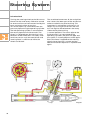
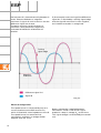
Neutral position
If force is not being applied to the steering wheel, the operating cylinder and pressure pipe are
connected to the fluid reservoir and no pressure is built up in the system.
285_021
In the interests of clarity, the rotary slide is illustrated with 6 instead of 10 grooves.
19
Steering System
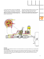
Left wheel lock
Turning the steering wheel to the left causes
the torsion bar and rotary slide to be turned
on account of the resistance exercised by the
tyres and road surface to turning.
This action opens up a fluid duct from the
pressure pipe to the right operating cylinder.
The left operating cylinder is connected to
the return pipe to the fluid reservoir. The
piston is subjected to a force acting in the
direction of left wheel lock. The rotary slide
continues to turn until the total piston and
steering force is sufficient to move the
wheels to left lock.
The associated movement of the rack pinion
also causes the lower part of the torsion bar
to be turned with the pilot bushing. This
movement is maintained until there is no
longer any turning of the torsion bar and
thus no angular offset between the rotary
slide and the pilot bushing
(= neutral position). The return pipe to the
fluid reservoir is re-connected to the
operating cylinders and pressure pipe and
the system is virtually depressurised again.
Each time force is applied to the steering
wheel, the torsion bar is turned and the
above-mentioned sequence is implemented
again.
285_081
20
In the event of forces acting in the opposite
direction, e.g. as a result of an uneven road
surface, the power steering has a cushioning
effect. This results in turning of the torsion
bar due to the force of the rack acting on the
pinion and torsion bar.
The rotary slide and pilot bushing are turned
towards one another out of the neutral
position. Fluid under pressure is then
conveyed to the operating cylinder chamber,
where it counteracts the rack movement.
285_022
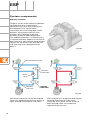
Example:
A bump in the road exerts force FA on the front wheels, causing the wheel to turn about point
D (to the right).
The resultant force at the rack (FZ) causes the pinion and torsion bar to turn. The fluid supply
to the right cylinder side is then opened up and the left side is connected to the return. The
reaction force FR at the piston and rack equalises the action of force FZ and thus prevents
turning of the wheel.
21
Steering System
Servotronic solenoid valve N119
The solenoid valve acts as electrohydraulic
converter for implementing the Servotronic
function. It is of the proportional type and
open when deenergised. The higher the
current level actuating the valve, the smaller
the opening cross-section.
285_023
Servotronic operation
The higher the vehicle speed, the lower the
force which has to be exerted by the driver
on the steering wheel when changing
direction. This basically applies to all steering
systems (with and without servo action).
Certain compromises therefore have to be
made when designing the steering.
It is important to avoid an impression of overlight steering at high vehicle speeds.
This is remedied by Servotronic.
The Servotronic regulates the actuating
torque at the steering wheel as a function of
vehicle speed.
The maximum servo action is provided when
the vehicle is stationary or moving very
slowly (e.g. when parking).
Pressure p (bar)
Actuating torque (Nm)
120 km/h
50 km/h
Low vehicle speed (e.g. when parking)
22
285_025
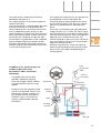
The Audi A8 `03 is fitted with the newly
developed Servotronic II.
This again operates on the active hydraulic
reaction principle.
The reaction piston is located above the pilot
bushing. The piston is connected to the
rotary slide and thus also to the torsion bar
and is supported by way of balls on the
centring element linked to the pilot bushing.
When the steering wheel and thus also the
torsion bar are not being turned, the balls
are located in a guide collar. Fluid is applied
to the chamber above the reaction piston.
The force exerted by the reaction piston on
the balls and thus on the pilot bushing varies
in line with fluid pressure.
The higher the fluid pressure, the greater the
force applied and thus the higher the
actuating torque to be exerted by the driver
on the steering wheel. The pressure control
element is the Servotronic solenoid valve
N119.
The valve is actuated by the onboard power
supply control unit -2- J520. The input signal
for the control unit is the vehicle speed signal
from the ESP control unit J104. The larger the
opening cross-section of the valve, the
smaller the drop in pressure at the valve and
thus the higher the pressure in the chamber
above the reaction piston.
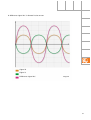
Different characteristic curves for steering
wheel actuating torque and steering system
pressure are thus obtained depending on
vehicle speed.
From
control unit
J104
In addition to its actual function, the
method of operation of the
Servotronic II offers two further
advantages:
– The guide collar for the balls
provides additional steering
centring. Straight ahead stability
is enhanced particularly at high
speeds.
– Fluid pressure and volumetric flow
rate are not reduced. This ensures
that there is always a safety margin for dealing with emergency
situations (e.g. in the event of
abrupt, unforeseeable steering
correction).
Control
unit J520
Torsion bar
Solenoid
valve N119
Reaction
piston
Balls
Centring
element
285_024
23
Steering System
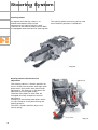
Steering column
As regards basic design, there is no
difference between the principal
components of steering columns with
mechanical and electrical adjustment. Both
are equipped with the electrical steering lock.
The steering wheel mounting splines now
have 72 detent positions instead of 6.
285_026
Steering column with mechanical
adjustment
Eccentric
The steering column is fixed in position by
means of two sets of plates with eight steel
plates each. Four plates each permit axial
adjustment. The recesses in the plates for
adjustment are arranged axially.
The other four plates on each side are
arranged vertically and permit vertical
adjustment.
Clamping is achieved by two rollers which
run up a ramp on a cam plate during the
locking process.
The lever is fixed in position by an overcentre spring.
Lever
24
285_027
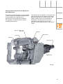
Steering column with electrical adjustment
Axial adjustment
The electric motor with gear unit and spindle
is permanently connected to the box rocker.
The guide box with steering unit is
permanently connected to the adjuster.
The spindle is screwed into the internal
thread of the adjuster.
Electric motor with
gear unit
Spindle
The rotation of the spindle is converted into
axial movement of the adjuster with guide
box and steering unit. A Hall sensor in the
electric motor measures the number of
revolutions. The control unit uses this
information to determine the current
position in the steering column adjustment
range.
Bracket
Box rocker
Adjuster
Steering unit
Guide box
285_028
25
Steering System
Vertical adjustment
The box rocker with guide box and steering
unit is swivel-mounted in the bracket.
The electric motor with flexible shaft, spindle
and gear unit is permanently connected to
the box rocker.
A threaded bush into which the spindle
engages is mounted in the bracket.
Rotation of the spindle produces vertical
movement of the threaded bush. The rocker
with guide box and steering unit is turned
about the joint pivot point.
The other end of the spindle is permanently
connected to a spur gear. A toothed belt
transmits the rotation to a spindle on the
other side of the steering column, where
adjustment takes place with identical
components. The two-sided mounting
system provides far more rigid attachment of
the steering column.
A Hall sensor in the electric motor measures
the number of revolutions. The control unit
uses this information to determine the
current position in the steering column
adjustment range.
Bracket
Guide box
Pivot point
Electric motor
Threaded bush
Flexible shaft
Spindle
285_029
Threaded bush
Spur gear
Toothed belt
Spindle
26
285_030
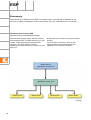
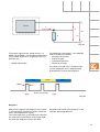
Steering column adjustment: Block diagram
Following initial assembly, the end positions
are approached in Z (vertical adjustment) and
X (axial adjustment) directions. These values
are stored in the onboard power supply
control unit J519.
Each time any further adjustment is made,
the Hall senders record the number of
revolutions of the corresponding adjustment
motor. The control unit J519 uses these
values and the stored end positions to
determine the current position of the
steering column in the adjustment range.
Switch for steering column
adjustment
± Z, ± X
Steering column electronics
control unit J527
Hall sender for
steering column
position Z
Motor for steering
column adjustment Z
Onboard power supply
control unit J519
Hall sender for
steering column
position X
Motor for steering
column adjustment X
Convenience CAN
Discrete wire
285_031
27
Steering System
Electrical steering column lock (ESCL)
Summary
The A8 `03 is the first Audi vehicle to be fitted with an electrical steering column lock.
Significant advantages have been achieved by installing the ESCL unit and the locking
mechanism at different locations:
– Passive vehicle safety: Space for additional knee guards
– Anti-theft protection: Components less accessible
– Costs: Arrangement of control unit, motor and gear unit in one assembly
Design:
The detent wheel with bevelled outer splines
is connected by means of a friction clutch to
the steering column tube. The axially
adjustable locking slide with bevelled inner
splines is mounted in the guide box.
The electric motor drives the spur gear by
means of worm gearing. The axially
adjustable reversing lever is mounted in the
ESCL unit and linked by way of the
connecting rod to the locking slide.
Locking slide
Detent wheel
Guide box
Steering
column tube
Electric motor
Connecting rod
Reversing lever
Spur gear
28
285_032
Operation:
Actuation of the motor turns the spur gear.
The side face of the spur gear takes the form
of a ramp. The reversing lever runs on this
ramp and is axially adjusted in line with the
position of the spur gear and ramp position.
The movement of the reversing lever is
transmitted directly to the locking slide.
Meshing of the locking slide and detent
wheel mechanically locks the steering
column.
The ESCL unit is connected to the steering column by way of shear bolts and can only be
replaced together with the steering column.
For information on operation and electrical function refer to SSP 287 Control Units.
Service:
The ESCL function can be checked with VAS 5051 using the control element test.
Matching is performed with the adaption function.
For details, refer to current Workshop Manual and assisted fault-finding.
29
Brake System
Summary
The principal new feature is the electrically
actuated parking brake.
Use is made of two new brake systems:
A 16-inch system for 6-cylinder engines and a
17-inch system for all larger engines.
Front axle
Engine
V6 engines
V8 engines
V6 engines
V8 engines
16"
17"
16"
17"
16" FNRG 60
Aluminium
floating frametype caliper
17" 2FNR 42 AL
Two pistons
Aluminium
floating frametype caliper
16" C II 43 EPB
Aluminium
floating caliper
17" C II 43 EPB
Aluminium
floating caliper
Number of
pistons
1
2
1
1
Piston
diameter (mm)
60
2 x 42
43
43
Brake disc
diameter (mm)
323
360
280
310
Min. wheel size
Type of brake
30
Rear axle
System components
Front axle brake caliper
A new design principle has been employed
(floating frame type FNR).
In this case the floating caliper is designed as
a frame, thus permitting a considerable
reduction in material thickness at the caliper
bridge.
For the first time it was possible to integrate
a brake disc of 360 mm diameter into
17" wheels. In the past, 18" wheels were
required for this brake disc dimension.
285_034
Caliper bridge
Holder
Rim Ø
sc
Di
Ø
FN
Rim Ø
sc
Di
Ø
FN
Disc Ø
FNR
285_035
Comparison of technologies: FN and FNR disc brake in the same wheel
Rear axle brake caliper
Use is made of an advanced aluminium
floating-caliper brake.
Brake disc diameter and pad area were
enlarged to adapt them to the front brake
dimension. This resulted in greater braking
power and a longer pad service life.
Corrosion resistance was improved by the
introduction of stainless steel pad springs and
greater pad clearance in the pad guides.
Further details were modified to optimise noise
level, braking comfort and environmental
compatibility.
The caliper concept was designed for use with
the electromechanical parking brake.
31
Brake System
Brake servo
Brake master cylinder
Use is made of a tandem vacuum-type brake
servo (8+9 inch, basic design as for A4 and
A6). In comparison to the A4 and A6, the
transmission ratio has been increased to 7:1.
The inlet valve flow characteristics have been
optimised and the valve closing distance
shortened. This results in far quicker and
more precise servo response accompanied
by a greatly improved operating feel.
With V8 petrol engines, vacuum is supplied
by a suction jet pump driven by the intake
manifold vacuum.
An electric vacuum pump is employed for the
V6 petrol engine.
Use is made of a tandem brake master
cylinder.
As compared to the A4 and A6, the piston
diameter was increased to 26.99 mm with a
total stroke of 36 mm (18/18).
The central valves of both brake circuits
(diagonal configuration) have been designed
for optimum flow. This permits the use of a
self-priming ESP unit without a separate
charging pump.
These changes and the above-mentioned
modifications to the brake servo result in a
significant reduction in pedal travel prior to
brake response in conjunction with less
pedal force. Active safety is thus enhanced
by shortening the stopping distance.
Brake fluid reservoir
The brake fluid reservoir is a separate
component fitted into the brake master
cylinder.
For design reasons, the brake fluid
reservoir is never to be completely
drained, as this would permit the
ingress of air into the pipes on account
of the position of the connections. Refer
to the current Workshop Manual for
procedure for changing brake fluid.
Brake fluid
reservoir
Brake servo
Brake master
cylinder
285_036
32
Notes
33
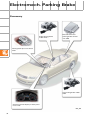
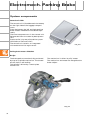
Electromech. Parking Brake
Summary
Right parking brake
motor V283
Electromechanical
parking brake control
unit J540
Parking brake pressure switch
F234
Left parking brake motor
V282
Control unit with display in dash panel
insert J285
285_091
34
Operation and display
The parking brake is actuated by the pressure
switch F234 in the centre console.
The brake is applied by pulling the switch.
It is released by pressing the switch and at
the same time pressing the brake or
accelerator pedal.
The electromechanical parking brake
can still be applied by pulling the switch
even when the ignition is off. The
ignition must however be switched on
for the brake to be released.
285_041
Application of the parking brake is indicated by the parking brake display in the dash panel
insert and a lamp in the switch.
Parking brake display
285_042
35
Electromech. Parking Brake
System components
Control unit J540
The control unit is fitted beneath the battery
on the right side of the luggage compartment.
From the battery, the left and right parking
brake motors V282/283 are actuated separately.
There are two processors in the control unit.
Release decisions are taken by both processors.
Data transfer is by way of the drive system
CAN (refer to "Data transfer").
The control unit contains an integrated
micromechanical tilt angle sensor.
285_043
Parking brake motors V282/283
Design:
The brake pads are mechanically tensioned
by way of a spindle mechanism. The thread
on the shaft is self-locking.
The spindle is driven by a swash plate
mechanism.
The mechanism is driven by a DC motor.
The mechanism and motor are flanged to the
brake caliper.
285_072
36
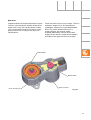
Operation:
Implementation of the parking brake function
involves translating the rotation of the drive
motor into a very short brake piston stroke.
This is achieved through the use of a swash
plate mechanism in conjunction with the
spindle drive.
There are three transmission stages. The first
reduction stage (1:3) is achieved by the
motor/gear mechanism input toothed belt
drive. The swash plate mechanism is
responsible for the second stage.
A speed reduced by a factor of 147 with
respect to the electric motor drive speed is
available at the gear mechanism output.
Toothed belt
Toothed belt
Gear mechanism
Electric motor
285_044
37
Electromech. Parking Brake
A spindle which drives the brake piston is
responsible for converting the rotation into a
stroke.
The spindle is driven directly by the swash
plate mechanism. A cylinder is mounted such
that it can slide axially in the brake piston.
Two plane surfaces stop the cylinder turning.
The flared section at the end of the cylinder is
provided with a forcing nut. Rotation of the
spindle moves the forcing nut on the spindle
thread.
The number of motor revolutions is
measured by a Hall sensor.
This enables the piston stroke to be
calculated by the control unit.
Brake piston
Spindle
Cylinder
Brake disc
285_045
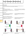
Parking brake application:
The nut moves forwards on the spindle. The
cylinder makes contact with the piston.
Cylinder and piston are pressed against the
brake disc.
Parking brake release:
The nut is screwed back on the spindle, thus
relieving the load on the cylinder.
The recovery of the sealing ring moves the
piston back and releases the brake disc.
285_046
38
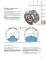
Mode of operation of swash plate
mechanism
A wheel (swash plate) with bevelled splines is
mounted on the input gear. It is mounted
obliquely with respect to the input gear shaft.
This causes the plate to wobble as the input
gear rotates.
The plate is fixed in position by keyways in
the gear housing. It cannot turn freely.
Electric
motor
Output gear
Swash plate
Toothed belt
Input gear
285_047
The swash plate has 51 teeth, the output gear
50 teeth.
As a result of this so-called "pitch error", the
swash plate teeth always make contact with
the flanks of the output gear and never
coincide with the tooth spaces.
Consequently, the output gear is moved on
by a small angle of rotation.
Swash
plate
285_048
39
Electromech. Parking Brake
Position 2
Swash plate
Two output gear teeth are meshed with two
swash plate teeth in the course of one
revolution of the input gear. The wobble
causes the second pair of teeth (position 2) to
be meshed after half a revolution of the
swash plate. In position 1, the output gear is
moved on such that the tooth of the swash
plate again makes contact with an output
gear flank in position 2. As a result of this
sequence, each half revolution moves on the
output gear and the spindle connected to it
by half a tooth face width.
Position 1
285_049
Functions
The following functions are provided by the electromechanical parking brake:
–
–
–
–
Parking brake function
Dynamic emergency braking function
Adaptive starting-off assistant
Brake pad wear recognition and play correction
Parking brake function
The tensioning force set by the system is
sufficient for all driving situations. A text
message in the dash panel insert centre
display warns the driver in the event of
gradients exceeding 30 %.
Activated status is indicated by lamps in the
switch and dash panel insert.
40
The brake is automatically re-tensioned if the
disc cools down after parking the vehicle. For
this purpose, the current disc temperature is
constantly established by way of a simulation
model in the control unit.
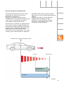
Dynamic emergency braking function
Pulling the parking brake pressure switch
F234 slows the vehicle at a maximum
deceleration rate of 8 m/s2.
Operation corresponds to that of the
handbrake lever. The vehicle is braked as long
as the switch is pulled. Braking action is
terminated on releasing the switch.
Actuation of the switch at vehicle speeds
below 8 km/h causes the parking brake to be
applied.
To prevent possible incorrect operation
(triggered for example by the front
passenger), active emergency braking
function is deactivated as soon as the
accelerator is pressed again.
If the vehicle is travelling at a speed of more
than 8 km/h, braking is implemented by the
ESP. With the accelerator pedal still pressed,
engine torque is reduced to idling level and
brake pressure is built up by the ESP
assembly at all four wheel brakes. The cruise
control system is deactivated if in operation.
Activation of emergency braking function
8 km/h
Vehicle halt
Electromechanical
parking brake
ESP (ECD)
285_050
41
Electromech. Parking Brake
Adaptive starting-off assistant
This function permits smooth hill starting
and stops the vehicle rolling back. The
function is only activated if seat belt is
fastened.
The tilt angle is measured by a sensor in the
control unit. In addition, the control action
makes allowance for engine torque,
accelerator pedal position and gear selected.
The parameters listed above govern the point
at which the parking brake is released when
driving off.
V282
Left parking brake motor
V283
Right parking brake motor
Tilt angle sensor
(integrated into control
unit)
Tilt angle
Accelerat
or pedal
value
Engine
torque
Engine
speed
Automatic calibration of the tilt angle sensor
and starting-off parameters takes place
constantly.
Whenever the vehicle is started on the flat, its
acceleration behaviour is evaluated and
adjusted for control purposes to the
parameter set stored in the control unit.
The function can be deactivated at the
workshop but not by the driver.
J540
Electromechanical parking brake
control unit
Drive system
CAN
J234
Airbag control unit
(belt interrogation)
Selector lever position
J217
Automatic gearbox
control unit
J220
Motronic control unit
Accelerator
pedal value
42
F125
Multi-function switch
285_051
Brake pad wear recognition and play
correction
The pad thickness is automatically
determined cyclically (approx. every 500 km)
with the vehicle stationary and the parking
brake not applied. For this purpose the brake
pad is moved out of neutral position (= end
position) towards the brake disc. The control
unit uses the value measured by the Hall
sender to calculate the brake pad travel and
thus the pad thickness.
Measurement is performed with the vehicle
parked, the ignition lock applied and the
parking brake released.
If drivers regularly use the parking brake, the
wear measurement may be less precise than
if the parking brake is seldom applied.
Special system functions
Pad change mode
Pad change is performed using the diagnosis
tester VAS 5051 with the parking brake not
applied.
In basic setting function 5, the cylinder is
fully retracted by the spindle drive (refer to
Releasing parking brake on Page 38). The pad
can be replaced after resetting the brake
piston with the special tool VAS T10145.
In basic setting function 6, the cylinder is
moved back towards the piston (refer to
Applying parking brake on Page 38).
The pad thickness is entered in adaption
function 6 (for detailed information, refer to
current Workshop Manual).
Roadworthiness test mode
Metered braking on a dynamometer is
necessary for checking parking brake
operation.
Roadworthiness test mode is recognised
after 3 seconds if the rear wheels are turning
at a constant speed of between 3 and 9 km/h
on the dynamometer roller.
Terminal 15 must be on for this purpose.
The parking brake application action is
modified by the control unit:
Each time the switch is actuated, the piston is
moved by a defined small amount and the
brake applied slightly more.
43
Electromech. Parking Brake
Emergency release
An applied parking brake can be released
mechanically if electrical actuation is no
longer possible or in the event of mechanical
problems with parking brake components.
An emergency key is provided for this
purpose in the vehicle tool kit.
The vehicle is to be jacked up and the
appropriate wheel removed.
The Torx head at one end of the key is used to
remove the actuator from the brake caliper.
The spindle can then be turned with the
opposite end of the emergency key until the
brake is released.
285_085
Fault displays
Flashes constantly if parking brake has not
been properly applied. Flashing on actuating
parking brake pressure switch F234 indicates
a wiring fault.
285_086
Fault detected by control unit restricting
operation.
285_087
System fault; vehicle should no longer be
driven for safety reasons.
285_088
44
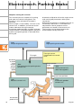
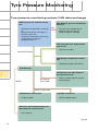
Electromechanical parking brake CAN data exchange
J540 Electromechanical parking
brake control unit
– Parking brake status (2)
– Tensioning force attained (2)
– Deceleration request (2)
– Deceleration request release (2)
– Terminal 15 status (2)
– Parking brake fault message (2)
– Fault lamp (6)
– Acoustic warning (6)
– Wear display (6)
– EPB text messages (6)
J255 Front climate control unit
(7)
– Ambient temperature
J518 Entry and start
authorisation control unit (5)
– Status of steering wheel lock
– Terminal 15 on
– S-contact
Convenience CAN
Diagnosis CAN
J533 Gateway (1)
– Mileage (old)
– Time (old)
J104 ESP control unit (2)
– Vehicle speed
– Wheel speed
– TCS/MSR request
– ABS braking
– ESP/EBPD intervention
– Brake pressure
– Front brake temperature/EPB
– Deceleration available
– EPB message plausible
– Quattro drive
J220 Motronic control unit (3)
– Engine speed
– Closed throttle position
information
– Accelerator pedal value
– Engine torque loss
– Driver input torque
– Clutch switch status
Dash
panel
insert
CAN
Drive
system
CAN
J285 Control unit with display in
dash panel insert (6)
– Displays
– Acoustic signals (gongs)
– Mileage
– Date
– Time
– Standing time
J217 Automatic gearbox control
unit (4)
– Gearbox status
– Target gear/gear engaged
– Selector lever position
– Torque converter lock-up
clutch status
J234 Airbag control unit
– Driver's belt buckle
interrogation
285_089
45
ESP
Summary
The Audi A8 `03 is fitted with the ESP 5.7 already used in the Audi A4. In addition to the
necessary software adaptation to the new vehicle, the main new features are as follows:
Communication interface ECD
(electronically controlled deceleration)
The interface enables other vehicle systems
to actuate the ESP. The ESP control unit J104
can be informed directly of deceleration
requests. The ECD request involves
deceleration of the vehicle at a maximum rate
of 8 m/s2.
Brake pressure is built up evenly at all four
wheels.
The interface in the A8 is used by the
electromechanical parking brake and
adaptive cruise control functions.
J428 Distance
regulation control unit
J104 ESP control unit
Wheel brake
Wheel brake
Wheel brake
Wheel brake
285_052
46
Active speed sensors
The new sensors detect the corresponding
wheel speed directly at the wheel bearing by
way of magnetic multipoles.
Direction of rotation and size of air gap are
also determined (refer to System
components for design and operation).
285_053
New software modules
The TCS function has been upgraded to
include improved traction on non-compacted
surfaces (e.g. deep snow).
Greater wheel slip values are accepted for
acceleration when travelling straight ahead
or with small steering angle.
Directional stability has priority when
cornering. The permissible slip values are
reduced.
ESP control action is reduced if a sporty
driving style is required. Directional stability
is maintained but larger float angles are
permitted, leading to higher wheel slip values
in transverse vehicle direction.
A sporty driving style is recognised from
evaluation of accelerator pedal actuation.
47
ESP
System components
Hydraulic modulator
The basic version of the hydraulic modulator
corresponds to that in the Audi A4.
Compliance with noise level requirements
with adaptive cruise control action
necessitates the use of integrated suction
dampers. These take the form of small
chambers which dampen brake fluid
pulsation by way of rubber diaphragms.
This modified modulator is used exclusively
in vehicles fitted with adaptive cruise control.
Attainment of a high level of braking comfort
requires the use of the linear solenoid inlet
and switching valves developed for the
ESP 5.7.
285_090
Solenoid switching valve
Solenoid
intake valve
Return
pump
Solenoid
inlet valve
Solenoid
outlet valve
285_055
ECD request not active: Valves deenergised
Driver can regulate brake pressure by way of
open solenoid switching and inlet valves.
48
Pressure build-up in response to ECD request:
Solenoid switching and intake valves
energised, return pump suction action via
open solenoid intake valve and pump
regulates brake pressure.
Mode of operation of linear solenoid valves
Application of current to the coil of the
solenoid valve causes a magnetic force FM to
act on the sealing element.
The sealing element is pressed onto the seat
in the valve housing. The forces exerted by
the spring (FF) and the hydraulic fluid (FH) act
in opposition to the magnetic force.
If FF+FH becomes greater than FM, the sealing
element is lifted off the seat and the valve
opens. The higher the valve actuation current,
the greater the hydraulic fluid pressure must
be to open the valve.
Varying the current level makes it possible to
set different opening pressures.
In addition, the valve stroke (= valve opening
cross-section) can be set in the range
between valve closed and valve fully open.
This mode of operation enables the brake
pressure to be varied as required.
Such action is a prerequisite for comfortable
vehicle deceleration.
FM
Coil
Sealing element
Spring
Seat
FF + FH
285_056
49
ESP
Speed sensors G44-47
Design:
The measuring element is a Hall sensor
consisting of three Hall elements.
The conventional sensor ring is replaced by a
magnetised wheel bearing seal carrying
48 pairs of north/south poles (multipole).
285_057
Operation
The sensor detects changes in magnetic
flux density.
The three Hall elements are in offset
arrangement. The gap between the
elements is selected such that element A
senses a magnetic maximum when C
detects a magnetic minimum.
Element A
Element B
Element C
285_058
50
A difference signal A-C is formed in the sensor.
285_057
Signal A
Signal C
Difference signal A-C
285_074
51
ESP
Hall element B is located centrally between A
and C. Element B detects a magnetic
maximum if signals A and C and thus also the
difference signal are at zero.
The point at which signal B reaches its
maximum value (positive or negative) is
evaluated for detection of direction of
rotation.
If, for example, zero crossing of the difference
signal A-C is reached by a trailing signal edge
and the signal B maximum is then negative,
anti-clockwise rotation is recognised.
Trailing
signal edge
Negative
maximum
Difference signal A-C
Signal B
285_075
Electrical configuration
The speed sensor is connected by way of a
current interface to the ESP control unit,
which is fitted with a low-impedance shunt R.
The speed sensor has two electrical
connections and forms a voltage divider
together with the shunt.
52
Battery voltage UB is applied between
connections 1 and 2. The sensor signal
produces a drop in voltage US at the shunt.
This signal voltage is evaluated by the control
unit.
1
Sensor
IS
3
UB
R
US
2
285_061
The output signal of the speed sensor is a
PWM signal (PWM = pulse width modulation).
The number of pulses in a specific time unit
provides the
– speed information.
The following information is encoded by
means of the pulse width:
– Direction of rotation
– Size of air gap
– Installation position
– Detection of stop
The correct air gap size is important for
system operation and is detected and
evaluated for system self-diagnosis.
North
South
North
Width
Speed information
285_062
Diagnosis
Within the scope of self-diagnosis the system
is monitored for mechanical faults, electrical
faults and implausible signals.
The most important system data are stored in
the measured value blocks and can be read
out with the diagnosis tester VAS 5051.
Detailed information can be found in the
relevant Workshop Manual.
53
Tyre Pressure Monitoring
Summary
The Audi A8`03 is fitted with a new version of the tyre pressure monitoring system, the
principal new features of which are described in the following.
Aerials
Use is made of active aerials.
The radio signals transmitted by the tyre
pressure sensors are converted by the aerials
into digital signals.
There are two aerial versions which differ in
terms of the carrier frequency (433/315 MHz)
to be processed.
Data transfer
The digital signals are transferred from the
aerials to the tyre pressure monitoring
control unit via the LIN bus.
The major advantage of this method is the
minimal susceptibility to electromagnetic
interference.
Tyre pressure monitoring control unit
The control unit is located beneath the rear
seat bench. There is no sensor signal
conditioning in the control unit.
Only one control unit frequency version is
required as the signals are already
conditioned in the aerials.
Sensor
Sensor
Aerial/
receiver
Aerial
LIN bus
HF cable
Control unit/
receiver
Control unit
285_063
1st generation components and networking
(Audi A8 up to `03)
54
285_064
2nd generation components and networking
(Audi A8 as of `03)
Control concept
System operation forms part of the MMI
control concept.
Pressing the CAR button and selecting
"Systems"- "Tyre pressure monitoring system"
provides a display of the current tyre
pressures and temperatures or enables the
following settings to be made:
– System activation/deactivation
– Storage of tyre pressures
(Refer to operating manual for detailed
information)
285_065
Warning displays
Warnings continue to be displayed in the dash panel insert.
The two-stage warning priority system has been retained
(refer to operating manual for detailed information).
55
Tyre Pressure Monitoring
Tyre pressure monitoring system CAN data exchange
J502 Tyre pressure monitor control
unit
– Allocation of identifiers to aerials
(1)
– Request for aerial messages (1)
– System status (all)
– Output of information (warnings,
system faults, pressure,
temperature) (2, 3)
R59...R62 Tyre pressure monitoring
aerials (1)
LIN
– Tyre pressure, temperature,
battery status of sensors
– Level of signals received
J518 Entry and start authorisation
control unit
– Terminal 15 status
Convenience CAN
J644 Energy management control
unit
– Load deactivation (LIN driver)
J533 Gateway
J285 Control unit with display in
dash panel insert (2)
MOST
Dash panel
insert CAN
– Status of warning and system
fault displays
Drive system CAN
J220 Motronic control unit
J104 ESP control unit
– Engine speed
– Vehicle-speed signal
J523 Front information display and
operating unit control unit (3)
– User request
285_067
56
Service
The range of service diagnosis options has
been extended.
Aerial diagnosis is performed constantly and
does not have to be started separately.
(For details, refer to current Workshop Manual
and assisted fault-finding)
57
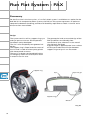
Run Flat System - PAX
Summary
For the first time in the luxury class, a "run flat" wheel system is available as an option for the
Audi A8 `03. As compared to other systems, the PAX run flat system represents an optimum
compromise between handling, comfort and durability requirements. Both a summer and a
winter version are available.
Design:
The system consists of rim, support ring, tyre
and tyre pressure sensor. All components
have been newly developed.
The rim is of a completely new geometrical
design.
The support ring is fitted onto the centre of
the rim and is made of a heavy-duty plastic
with honeycomb structure.
The tyre is no longer tensioned behind the
rim flange by means of its bead, but rather
inserted in the rim seat.
The geometrical and structural design of the
PAX tyre differs considerably from
conventional tyres, above all in the area of
the side wall and bead.
A glycerine gel is applied to the inner surface
of the tyre to reduce the friction between
support ring and tyre in run flat mode.
Support ring
Tyre
Glycerine gel
Support ring
Wheel
285_068
58
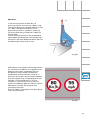
Operation:
In the event of partial or total loss of
pressure, the tyre rests on the support ring.
The special design of the bead seating on the
rim stops a flat tyre coming off. This is
particularly critical in situations involving
cornering with the tyre side wall subject to
tensile load.
The tensile force Fz causes the tyre bead to
rotate about the bead core, thus producing a
force Fw in the outer bead area which presses
the bead more firmly onto its seat.
Fz
Fw
285_069
PAX enables a fully laden vehicle to be driven
for a maximum of 200 km at a speed of max.
80 km/h even with a completely flat tyre.
Despite the use of the gel, component
temperature and hence wear increase, in
particular on account of the friction between
tyre and support ring. A high degree of ride
comfort is maintained even in run flat
situations. A loss of pressure is thus not
always immediately apparent. For this reason,
PAX always includes the tyre pressure
monitoring function.
Run flat mode is indicated on the dash panel
insert centre display.
285_070
59
Run Flat System - PAX
New tyre designation
PAX tyres have a new designation.
Arithmetically, the wheel used for the A8 corresponds to a wheel size of 18.3".
Tyre width [mm]
Speed symbol
Tyre diameter [mm]
Load index
Wheel diameter [mm]
285_068
Service
Tyre removal/fitting involves completely new procedures.
New tyre fitting machines and PAX attachments for conventional fitting machines are
available.
60
285
All rights reserved. Subject to
technical modification.
Copyright* 2002 AUDI AG, Ingolstadt
Department I/VK-35
D-85045 Ingolstadt
Fax 0841/89-36367
000.2811.05.20
Technical status as at 07/02
Printed in Germany