1
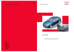
332
Vorsprung durch Technik www.audi.de
Service Training
Audi A3 Sportback
Self-Study Programme 332
All rights reserved.
Technical specifications
subject to change without
notice.
Copyright
AUDI AG
I/VK-35
[email protected]
Fax +49-841/89-36367
AUDI AG
D-85045 Ingolstadt
Technical status: 05/04
Printed in Germany
A04.5S00.11.20
Self-Study Programmes on the Audi A3
Audi A3 Sportback
SSP 279
Audi is defining a new segment in the premium
compact class. The A3 Sportback is characterised by
the sporting elegance of a coupé and the versatility
of a 5-door.
–
–
–
–
The Audi Sportback is deliberately going its own,
new way in the compact class. It offers the
emphatically sporty qualities and the athletic styling
of the three-door version with which it shares its
drive train, dynamic suspension and wheelbase.
In addition to two rear doors, it offers even more
space and variability thanks to its rear end which is
a total of 68 millimetres longer than on its threedoor
counterpart.
Order number: 240.2810.98.20
Engine
Injection system
Operating modes
Exhaust treatment
332_084
SSP 290 Audi A3 ‘04
–
–
–
–
–
–
–
–
The A3 Sportback is immediately recognisable at
first glance in the rear-view mirror by its striking
single-frame radiator grille, the distinctive tapering
of the sides and the dynamic shape of the clearglass
headlights.
The silhouette of the A3 Sportback when viewed
from the side becomes flatter towards the rear of
the car in typical coupé fashion and combines with
the gently rearward sloping roof line and the
restyled rear end to give the car its dynamic overall
proportions.
332_085
Introduction
Body
Engine
Gearbox
Running gear
Electrical system
Heating/air conditioning
Service
Order number: A03.5S00.01.20
SSP 293 Infotainment
–
–
–
–
Infotainment
Sound system
Radio module
Navigation
Order number: 000.2811.13.20
332_086
SSP 312 Audi A3 ‘04
–
–
–
–
Control units
Distributed functions
Infotainment
Occupant protection
Order number: A03.5S00.03.20
332_087
SSP 313 Audi A3 ‘04 Running Gear
–
–
–
–
–
–
332_074
Axles
Steering
Brake system
ESP
Wheels / tyres
Hand and foot controls
Order number: A03.5S00.04.20
332_088
Excellence in design & performance
Contents
Introduction . . . . . . . . . . . . . . . . . . . . . . . . . . . . . . . . . . . . . . 4
Body . . . . . . . . . . . . . . . . . . . . . . . . . . . . . . . . . . . . . . . . . . . . 6
Occupant protection . . . . . . . . . . . . . . . . . . . . . . . . . . . . . 12
Engine . . . . . . . . . . . . . . . . . . . . . . . . . . . . . . . . . . . . . . . . . . 22
Running gear. . . . . . . . . . . . . . . . . . . . . . . . . . . . . . . . . . . . 38
Convenience electronics . . . . . . . . . . . . . . . . . . . . . . . . . . 44
Infotainment . . . . . . . . . . . . . . . . . . . . . . . . . . . . . . . . . . . . 50
The Self-Study Programme conveys basic principles with regard to the design and function of new models,
new automotive components or new technologies.
The Self-Study Programme is not a Repair Manual!
All values given are intended as a guideline only, and refer
to the software version valid at the time of publication of the SSP.
For maintenance and repair work, always refer to the current technical literature.
Reference
Note
Introduction
Overview
Dimensions of the A3 Sportback.
332_051
4
Body
The body of the Audi A3 Sportback has a highly rigid and crash-optimised occupant cell.
Special attention was given to the following aspects:
●
the body rigidity,
●
the steering column rigidity,
●
local rigidity in highly stressed areas,
●
interior acoustics and driving comfort,
●
the crash optimised body structure and
●
the hybrid construction of the front end.
Front view of the body-in-white
332_048
Rear view of the body-in-white
332_049
By using state-of-the-art calculation and simulation methods, new materials and joining
techniques, and by optimising the joining sequence during the bodyshell assembly process, it was possible to
increase body rigidity by 20% compared to the predecessor model and enhance the crash performance of the
body structure.
5
Body
Materials
Bodyshell
Ultra-high-strength and higher-strength sheet metal
are used in areas which are subjected to high
mechanical stresses during a crash.
Welded tailored blanks and deep-drawn sheet metal
are used in other areas.
Ultra-high-strength sheet metal
higher-strength sheet metal
6
332_052
7
Body
Materials
Doors, sills and floorpan
Welded tailored blanks and tailored blanks with
flexible rolled wall thickness are used in the front
floorpan assembly and door areas.
The result is a distribution of material which
provides optimum stress absorption.
The sills are reinforced using rolled profiles. Rolled
profiles have a high strength-to-weight ratio.
Rolled profile
Tailored blanks
Tailored blanks
Rolled profile
Tailored blanks
332_053
8
Joining technique
Various joining techniques
are applied to interconnect the individual body
elements.
Spot welding joining
Laser soldering
Crash-relevant and
rigidity-defining
joints are spot-weld bonded using a high-strength
structural adhesive.
The overall length of the bonded seams is approx.
26 m.
Laser-solder joining is used to achieve a better
design and higher rigidity in the area of the
invisible joint and boot lid.
The total length of the laser-soldered joints is
approx. 3.3 m
Plasma soldering
Laser welding
Laser welding is used in areas which are not easily
accessible.
The total length of the laser welded joints is approx.
25 m.
Laser-welded joints
Laser-soldered joints
Plasma-soldered joints
To ensure the high rigidity and good design of the
water channel,
materials are joined by plasma soldering.
The overall length of the plasma-soldered joints is
approx. 1.1 m.
332_071
9
Body
Roof rail
Description
The Audi A3 Sportback has a roof rail whose new
style design accentuates the car's coupe like
roofline.
It is made from aluminium and is available in two
finishes:
– high-gloss anodised or
– black powder-coated
Mounting bolts
332_019
Mounting
Roof
The roof rail is mounted to the
roof side member using four bolts.
Rivet nut
Roof side member
exterior
Tolerance
compensation
element
Bolt
Nut-and-washer assembly
Head airbag
332_047
10
Open Sky roof
Description
Function
The optional Open Sky roof creates a more pleasant
interior climate. It lets more light into the car and
allows the occupants a view of the sky above.
The front glass segment can be opened completely
and slid back.
Two separate sun blinds protect against the glare of
the sun and can also be used when the glass roof is
open.
Opening is powered by an electric motor.
When opening, the glass roof moves upwards and
outwards.
Operation is by pushbutton. The glass roof halts in
the position in which the pushbutton is released.
Open Sky roof open
332_055
Open Sky roof closed
332_054
11
Occupant protection
Safety system
Like the system in the Audi A3 3-door, the safety system in the Audi A3 Sportback is built to the highest
standards. The long list of safety requirements includes full compliance with legislation currently in force, as
well as consumer tests with the aim of achieving class-leading car safety ratings for the new Audi A3
Sportback. Audi's internal requirements often present the development team with additional challenges.
Special emphasis was placed on a high level of occupant protection in accidents and on compatibility. Audi's
"safety first" approach to vehicle design complements the information derived from scientific analysis of
actual accidents and their impacts. To this end, the Audi Accident Research Unit ( AARU) analyses the data
from accidents involving recent Audi vehicles. The task of the research team is to analyse and reconstruct
accidents, and to identify areas where there is potential for improvement. In addition to this, the AARU
evaluates the information stored in the respective accident databases.
The differences to the Audi A3 `04 are highlighted on the following pages.
The safety system in the Audi A3 Sportback consists of the following components:
–
–
–
–
–
–
–
–
–
–
–
Airbag control unit
Dual-stage driver and front passenger airbags
Front side airbags
Sideguards (head airbags)
Side impact detection sensors on the C-pillar
Side impact detection sensors in the front doors
Crash sensors for differentiated head-on collision detection, otherwise known as "upfront" sensors
Front belt tensioners
Battery disconnector, only for models with battery in luggage compartment
Switches in the front seat-belt buckles
Seat occupied sensor, front passenger side
The vehicle can also be equipped with rear side airbags and a keyswitch with associated warning lamp for
deactivating the front passenger airbag.
The active head restraints in the front seats round off the safety system in the Audi A3 Sportback.
Legend
Note
Follow the safety instructions in the repair
manual before performing any work on the
airbag system!
12
E224
E24
E25
Front passenger side airbag deactivation key switch
Driver side belt switch
Front passenger side belt switch
G128
G179
G180
G256
G257
G283
G284
Seat occupied sensor, front passenger side
Side airbag crash sensor, driver side (front door)
Side airbag crash sensor, front passenger side (front door)
Rear side airbag crash sensor, driver side (C-pillar)
Rear side airbag crash sensor, front passenger driver side (C-pillar)
Driver side front airbag crash sensor (frontend left)
Front passenger side front airbag crash sensor (frontend right)
332_004
J220
J234
J285
J393
J533
Engine control unit
Airbag control unit
Control unit with display in dash panel insert
Convenience system central control unit
Data bus diagnostic interface (Gateway)
K19
K75
K145
Seat belt warning system warning lamp
Airbag warning lamp
Front passenger side airbag deactivated warning lamp
(PASSENGER AIRBAG OFF)
Airbag igniter, driver side
Driver side airbag igniter -2Front passenger side airbag igniter 1
Front passenger side airbag igniter 2
N95
N250
N131
N132
N153
N154
N199
N200
N251
N252
N253
Driver seat belt tensioner igniter -1Front passenger seat belt tensioner igniter -1Side airbag igniter, driver side
Side airbag igniter, front passenger side
Driver side curtain airbag igniter
Front passenger side curtain airbag igniter
Battery isolation igniter
T16
16-pin connector, diagnosis connection
13
Occupant protection
Airbag control unit J234
The airbag control unit's hardware and electronics have been modified compared to the control unit in the
Audi A3 3-door such that they are also capable of activating the dual-stage front airbags. The airbag control
unit has also been modified in such a way that no mechanical safing sensor is required.
The airbag control unit is integrated in the drive train CAN bus.
The airbag electronics basically have the following
tasks:
– collision detection (front, side, rear)
– defined deployment of the airbags or front
airbag stages, belt tensioners and battery
disconnector
– activation of the belt-on indicator
– evaluation of all input information
– continuous monitoring of the entire airbag
system
– capacitor-based independent power supply for
a defined period of time
(approx. 150 ms)
– fault display by failure warning lamp
– storage of fault/ and
collision information
– notification of a collision event to other system
components via the drive train CAN-bus or
a discrete collision output (conventionally wired)
Information about the occurrence of a crash is
utilised by other control units for opening the
central locking system, shutting off the fuel supply
and activating the hazard warning light system, etc.
Rear collision detection
If the airbag control unit recognises a rear collision whose severity exceeds the predefined deployment
threshold, then it ignites the belt tensioners and, where fitted, the battery isolation igniter.
14
332_005
Crash sensors for side protection system
Side airbag crash sensors, G179, G180
(in the front doors)
For the first time in the Audi A3 Sportback, pressure
sensors will be installed in the two front doors.
In a side impact, the deformation of the vehicle
causes a rapid increase in air pressure in the door
cavity. This increase in pressure is detected by the
sensor and signalled to the airbag control unit.
Rear side airbag crash sensors,
G256, G257
(C-pillar)
The two rear side airbag crash sensors G256 and
G257, which are installed in the C-pillar area on the
left and right hand sides, are conventional
acceleration sensors which are already being used
in the Audi A3 3-door.
Side impact sensors for the side
airbag are integrated in the front
door
332_006
Note
The airbag control system uses sensors integrated in the front doors, etc. To avoid any
impairment to the function of the side airbags, no modifications should be made to the doors
and door trims (e.g. retrofitting of loudspeakers).
Damage to the front doors can cause impairment of system functions. All work on the front
doors should be referred to a specialist workshop.
Belt-on indicator
The new Audi A3 Sportback has the belt-on indicator
function for driver and front passenger as known
from the Audi A6 ´05.
For further information, refer to Self-Study
Programme 323, Audi A6 ´05.
Seat belt warning system warning lamp
332_007
15
Occupant protection
Airbag
Front airbags
Dual-stage gas generators are employed in the front airbags.
The impact load acting on the driver and front passenger during an accident is reduced by radial inflation of
the driver side airbag and by time-staggered ignition of the propellant charges. The airbag control unit
controls the time interval between the two deployments depending on the severity and nature of the accident.
The time interval can vary between approx. 5 ms and 40 ms.
In any event, both propellant charges are ignited. This ensures that no propellant charge remains active after
an airbag deployment.
Driver airbag, N95, N250
The driver airbag uses two pyrotechnic propellant charges.
The airbag control unit activates the electrical detonator of the first propellant charge. The detonator ignites
the priming charge, which in turn detonates the actual propellant charge through nozzle holes in the gas
chamber. The combustion of the propellant charge produces a pressure inside the gas generator. If the gas
pressure exceeds a defined threshold, then the gas generator housing deforms and allows the gas to flow
through the metal filter to the airbag. The airbag unfolds and is inflated by the gases resulting from
combustion of the propellant charge. After a preset time delay, the airbag control unit energises the second
electrical detonator, which directly ignites the secondary propellant charge. When a preset pressure is
reached, the developing gas lifts the cap off the second-stage chamber and flows into the first-stage
combustion chamber. From here, the gas flows through the filter to the airbag.
Housing
Cap
Propellant charge 1
Propellant charge 1
Metal filter
Nozzle holes
Propellant charge 2
Priming charge
Detonator 1
Detonator 2
332_032
16
Ignition of the first propellant charge
332_033
Ignition of the second propellant charge
332_034
17
Occupant protection
Front passenger airbag, N131, N132
Unlike the driver airbag, the gas generator in the front passenger airbag works by the hybrid gas principle.
The gas generator consists of two pyrotechnic propellant charges which are integrated in a pressurised gas
bottle.
The detonator activated by the airbag control unit ignites the first propellant charge by means of the priming
charge. Should the pressure developing inside the gas bottle exceed a preset value, the rupture disc will
explode and the gas mixture will inflate the airbag. The airbag is further inflated by the combustion of the
second propellant charge .
The coil springs ensure that the propellant charges burn as intended.
Detonator 1
Priming charge 1
Propellant charge 1
Coil spring
Filter
332_013
Detonator 2
Priming charge 2
Propellant
charge 2
Coil spring
Rupture disc
Pressurised gas bottle
Gas:
argon approx.
98%
helium approx.
2%
Pressure:
approx. 250 bar
Side airbags, N199, N200
Like the airbags used in the Audi A6 ´05, the side airbags used in the Audi A3 Sportback are modules.
For further details, refer to Self-Study Programme 323, Audi A6 ´05.
So-called pyrotechnic tubular gas generators are used as gas generators.
If the airbag control unit detects a side impact which meets the criteria for deployment, then it energises the
relevant side airbag detonators. The primary charge is ignited by means of the priming charge. The
developing gas flows through the metal filter into the airbag.
Air outlet
Metal filter
Priming charge
332_027
Air outlet
18
Propellant charge
Detonator
Head airbags, N251, N252
Sideguards
The sideguard covers almost the entire side window
area. With these modules, the hybrid gas generator
is installed in the rear roof area and inflates the
airbag through a gas lance.
Connector
Gas lance
The support is mechanically propelled out of its
mount through the detonation of the propellant
charge.
The helium stored in the pressurised gas bottle at
600 bar now breaches the rupture disc.
The gas flows through the filter into the gas lance
which connects the airbag to the gas generator.
Gas generator
332_037
Gas lance
Filter
Support
Rupture disc
Propellant charge
Pressurised gas
bottle
332_035
332_036
Active head restraints
The task and function of the active head restraint
are described in Self-Study Programme 312, Audi A3
´04 Electrical System.
For further information, refer to this Self-Study
Programme.
Functional unit
"active head
restraint"
Lumbar support
plate
326_024
19
Occupant protection
Battery isolation igniter, N253
The battery isolation igniter has the same task as
the battery cut-off relay.
This involves disconnecting the starter and
alternator leads from the vehicle battery in the event
of a crash. The battery isolation igniter is used only
on models whose battery is installed in the luggage
compartment.
The battery isolation igniter is activated and
monitored for diagnosis by the airbag control unit.
Every time the airbag is deployed, the battery
isolation igniter is activated and must be
subsequently replaced.
When the pyrotechnic propellant charge is ignited,
the developing gas pressure displaces the bolt
located on a piston and breaks the connection
between the two battery terminals.
332_014
Battery isolation igniter
Battery isolation igniter activated
Pin and piston
combination
Pin
Connecting
element with
terminals
Detonator
332_030
20
Connecting
element with
terminals
Detonator
332_031
Seat occupied recognition system
for the North American market
The seat occupied recognition system for the North American market has been carried over from
the Audi A6 ´05.
However, the individual components have been adapted to suit the Audi A3 Sportback.
The system is described in Self-Study Programme 323 Audi A6 ´05.
The system has the following component parts:
–
–
–
–
–
–
–
–
Seat squab
Sensor mat for seat occupied recognition
Pressure sensor for seat occupied recognition , G452
Seat occupied recognition control unit, J706
Front passenger side belt switch, E25
Seat belt force sensor for seat occupied recognition, G453
Front passenger side airbag deactivated warning lamp, K145 (PASSENGER AIRBAG OFF)
Airbag control unit, J234
Front passenger side airbag
deactivated warning lamp
Seat squab
Belt-fastened sensor
switch
Airbag control unit
Belt force sensor for
seat occupancy
Sensor mat for seat occupied
recognition
Plug connection
below the seat
Pressure sensor for seat
occupied recognition
Seat occupied recognition
control unit
Disconnection point
326_019
21
Engine
2.0l 4-cylinder turbo FSI
The new turbo FSI engine is a progression on the 2.0l 4-cyl. FSI engine with stratified petrol direct injection
which combines the advantages of direct injection combustion with the dynamics of the exhaust turbo
technology. The result is an extremely responsive unit which conveys a highly enjoyable driving experience.
Reference
You will find a description of the
design and function of the
2.0l FSI engine in
SSP 279.
332_001
22
The engine number can be found at the bottom
lefthand side of the engine block in the area of the
gearbox flange.
* AXX12
3 4 5 6*
332_029
Torque/power curve
Torque in Nm
Power output in kW
Engine speed in rpm
332_015
Specifications
Engine code
AXX
Type
In-line 4-cylinder petrol engine
Displacement
1984 cm3
Power output
147 kW (200 bhp)
Torque
280 Nm at 1800-4700 rpm
Bore
82.5 mm
Stroke
92.8 mm
Compression ratio
10.5:1
Weight
approx. 152 kg
Firing order
1-3-4-2
Engine management
Bosch Motronic MED 9.1
Variable valve timing
42° crank angle
Exhaust gas recirculation
Inner EGR
Exhaust emission standard
EU 4 / ULEV
23
Engine
Crankshaft
The crankshaft has been modified to meet the
tougher demands of the turbo FSI engine, resulting
in higher component strength and enhanced
acoustics.
The flanges on the main bearings and the conrod
journal have been enlarged for greater rigidity. This
way, the rigidity specifications have been met
despite the 6.4 mm increase in stroke length.
Flanges
332_020
Engine mass balancer unit
The balancer shaft gear has been adopted from the
naturally aspirated engine with respect to its
operating principle and position. However, the
following modifications were necessary:
●
separation of the gearing and imbalance masses
to improve balancing
●
oil pump with wider gear
●
clean oil controlled pressure regulator with
pressure control on the raw oil side close to the
oil pump,
integrated in the balancer shaft housing
●
strength optimised die-cast housing
●
the balancer shafts are mounted directly in the
aluminium housing
●
decoupled final drive sprocket in the balancer
shaft drive gear
Drive gear
Crankshaft
Imbalance gears
Balancer shaft
housing
Balancer shafts
Intake line
Final drive sprocket
Oil pump
332_021
24
Decoupled final drive sprocket
The higher torsional irregularity in the crankshaft of the turbo engine at the bottom end of the RPM range
results in much greater chain forces in the balancer shaft chain drive. The oscillation angle of 2° crank angle in
the turbo engine is significantly higher than the relative oscillation angle of 0.8° crank angle in the naturally
aspirated engine. The sudden load on the chain drive would subject the chain to increased wear unless
measures are taken. For this reason, bow springs have been integrated into the sprocket wheel hub. They
decouple the input shaft of the balancer shaft module from the crankshaft. This device functions similarly to
a dual-mass flywheel.
Diamond coated disc
Hub
Plain bearing
Bow spring (2x)
Sprocket wheel
Friction disc
Diaphragm spring
Cover disc
332_022
Chain load with and without decoupling
Tensile force
Maximum value
Mean value
Minimum value
Chain force in (N)
Chain load without decoupling
Critical range
(zero transitions)
Tensile force
Maximum value
Mean value
Minimum value
Chain force in (N)
Chain load with decoupling
332_016
25
Engine
Toothed belt drive
As with all Audi 4-cylinder inline engines, the timing
gear is designed as a toothed belt drive and directly
drives the exhaust camshaft.
The toothed belt tensioning system carried over
from the naturally aspirated engine has been
modified to meet the much higher demands placed
on the toothed belt drive including:
●
turbo-related higher valve spring pressures
●
turbo-related valve timing associated with the 42°
crank angle adjustment range of the continuous
variable valve timing on the intake camshaft
●
high-pressure pump drive by a triple cam on the
intake camshaft.
Function
The toothed belt sprocket is positioned on the
crankshaft at TDC of cylinder 1, as shown in
Fig. 332_023. When the working cycle begins, high
tensile forces act on the toothed belt. They are
reduced by the elliptical shape of the toothed belt
sprocket because the flat side of the sprocket gear
allows a slight slackening of the toothed belt. The
resulting torsional vibration counteracts the
torsional vibration of the 2nd engine order at the
antinode of the timing gear without producing too
much excitation in the other RPM ranges.
The result is the elliptical toothed belt sprocket on
the crankshaft.
The CTC toothed belt sprocket* used here for the
first time greatly reduces the torsional vibration of
the camshaft and the tensile forces acting on the
toothed belt.
* CTC toothed belt sprocket = crankshaft torsional
cancellation
332_023
26
Cylinder head
The following turbo-specific modifications were
made to the cylinder head (in relation to the
2.0l FSI):
●
sodium-filled exhaust valves
●
intake valves with reinforced seats
●
roller rocker fingers optimised for rigidity with
a reduction in cam and roller land width
●
valve springs rated for increased spring forces
(identical valve springs are used for the intake
and exhaust valves)
In addition, the intake port geometry has been
revised, enhancing the tumble effect along with
knock resistance and running smoothness.
The high-pressure pump mounted on the cylinder
head has been installed rotated through 90°.
2.0l 4V FSI
332_002
2.0l 4V T-FSI
332_017
27
Engine
Crankcase ventilation
A permanent vacuum is maintained in the cylinder
crankcase by separate ventilation of the cylinder
crankcase and cylinder head, since the crankcase
breather is connected to the intake manifold.
The blow-by gases flow from the crankcase into the
cylinder head through the primary oil separator in
the oil filter module.
Here the blow-by gases mix with the gases from the
cylinder head and flow through a labyrinth, where
a secondary oil separation stage takes place.
Since a turbo engine requires a more sophisticated
pressure control system, a two-stage pressure
control valve which branches off the blow-by gases
to the intake manifold or from the turbocharger is
installed on the cylinder head cover. If a vacuum is
present inside the intake manifold, the
blow-by gases flow directly into the intake manifold.
If a boost pressure is present, a non-return valve in
the pressure control valve housing closes and the
blow-by gases flow through a port into the cylinder
head cover ahead of the turbocharger. A so-called
diagnosis channel has been integrated to detect
faulty installation of the pressure control valve. If
the pressure control valve is not installed correctly,
unmetered air penetrates the pressure control valve
seal on the cylinder head cover. Unmetered air is
diagnosed by the reaction of the lambda probe.
if a boost pressure is present upstream of turbocharger
if a vacuum is present in the intake manifold
Exhaust turbocharger gas
outlet
Intake manifold gas
outlet
Labyrinth in cylinder head cover
Central crankcase gas
inlet
Oil filter module
Non-return valve
Non-return valve
Pressure control valve
Diagnosis channel
332_057
28
Exhaust turbocharger/manifold module
Due to the constraints on available space, a modular package comprising an exhaust manifold and turbine
housing has been developed for the respective longitudinal and transverse mounting drive train variants.
Special emphasis was placed on implementing a service solution for the easy removal and installation of the
exhaust manifold and the integration of a close-coupled catalytic converter.
Crankcase breather
connection
Coolant flow to radiator or
from auxiliary water pump
ACF connection
Pressurised oil inlet
Turbocharger divert air valve
N249
Coolant inlet from engine
block
332_024
The turbine shaft mounting is integrated in the compressor housing. The air intake includes connections for
crankcase and ACF ventilation. A specially adapted silencer for the reduction of pressure pulsation noises is
attached to the pressure connection.
The required boost pressure is set by means of charge pressure control solenoid valve N75 (on the 1.8 turbo it
functions as an overpressure control unit) and a so-called "wastegate". An electrical turbocharger divert air
valve N249 is used to avoid "overbraking" of the turbocharger turbine when the engine is in overrun with the
throttle valve closed and boost pressure still present.
The charge pressure control solenoid valve N75 and the turbocharger divert air valve N249 are located on the
turbocharger.
29
Engine
A clamping flange on the cylinder head allows easy
removal and installation of the module with
a minimum of bolting.
The terminal block does not have to be detached.
Terminal block
332_025
The exhaust manifold is designed as a split
manifold. A divider is integrated in the manifold to
ensure a steady flow of exhaust gases onto the
turbine wheel. The ports of cylinders 1 and 4 and
cylinders 2 and 3 are separated according to the
firing order. Furthermore, the divider prevents the
exhaust gas pressure from expanding into ports of
the other cylinders.
Cylinder 1
This allows the required turbine speed to be
maintained and optimises turbocharger response.
Divider
332_026
30
Charge air ducting and boost pressure control
The boost pressure and intake pressure are
converted to a control pressure by the pulsed
charge pressure control solenoid valve N75. The
applied control pressure acts on the pressure unit
which actuates the wastegate flap by means of
a linkage. The wastegate flap opens a bypass which
allows some of the exhaust gases to flow past the
turbine wheel to the exhaust system. With this
control system, it is possible to regulate the turbine
speed and set the maximum boost pressure.
Note
In the event that the control system fails,
the boost pressure will act directly on the
pressure unit and against its spring
pressure. In this way, the maximum boost
pressure is reduced to a base boost
pressure.
Turbocharger divert air valve N249
Charge pressure control
solenoid valve N75
Wastegate
Brake booster servo
Pressure unit
Vacuum pump
Water connection
Activated charcoal
filter system solenoid
valve 1 N80
Oil filter module
Charge air cooler
332_011
31
Engine
Air divert control in overrun
If the throttle valve is closed when the engine is in overrun, a back pressure will develop in the compressor
housing due to the continuing presence of boost pressure. This back pressure noticeably reduces the speed
of the compressor wheel, the net result of which is in a reduction in boost pressure and increased turbo lag.
To avoid this, the turbocharger divert air valve N249 is opened by an electrical actuator. The valve opens a
bypass which allows the compressed air to flow back to the intake side of the compressor circuit via the
compressor wheel. In this way, the required turbine speed is maintained. The turbocharger divert air valve
N249 closes when the throttle valve opens and the boost pressure is immediately available again.
Overrun mode
Air intake
from air filter
Divert air valve open
Engine running under load
Divert air valve
closed
332_012
32
Cooling system
To prevent carbon build-up on the turbine shaft in the turbocharger, an auxiliary water pump provides
additional water circulation for up to 15 minutes after the hot engine is shut off. The pump transports the
lower-temperature coolant against the direction of flow. The coolant, which is taken in by the auxiliary water
pump, flows from the radiator through the turbocharger to the engine block and back to the cooler to
dissipate stored heat.
Connection
Heat exchanger
Connection
Expansion tank
Water port
Engine block connection
Connection
Exhaust-driven
turbocharger
Coolant thermostat
Radiator inlet
Radiator outlet
Oil cooler
Auxiliary water pump
332_028
33
Engine
Tumble flaps
As the engine is operated in homogeneous-charge
mode only, tumble flaps are used to improve
mixture formation inside the engine.
They are actuated:
– to improve idling quality when the engine is cold
– to improve charging efficiency at engine start-up
– in overrun
– in homogeneous split mode (HOSP)
High-pressure rail
Plastic flap with steel
shaft
High-pressure/lowpressure fuel port
Intake air temperature sensor
Throttle valve actuator
Pressure limiting
valve
ACF system with
double non-return valve
Activated charcoal
filter valve
Tumble flap actuator
332_058
Operating mode
34
HOSP
Homogeneous split for rapid heating-up of the catalytic converter
Lambda value
approx. 1.05
Intake manifold flap
closed on one side (to enhance tumble effect)
Throttle valve
wide open
Injection timing
first injection approx. 300° before ignition TDC, second injection with a reduced amount
of fuel approx. 60° before ignition TDC
Ignition timing
retarded, mixture ignites very late, exhaust valves already open, exhaust gas temperature
rises rapidly. The catalytic converter reaches its operating temperature rapidly.
Fuel supply
The new direct-injection petrol engines are supplied by a demand-controlled fuel pump. This demand control
was developed to minimise the energy demand of the fuel pump and save fuel.
The fuel pump supplies only as much fuel as is required by the engine while maintaining the required system
pressure. This task is performed by the Engine Control Unit (ECU) and an electronic power module which
controls fuel pump speed by pulse width modulation.
High-pressure pump
Fuel pressure control valve N276
Triple pump cam
High-pressure injector
Fuel pressure sender,
low pressure
G410
Low-pressure fuel circuit
High-pressure fuel circuit
Pressure limiting valve
Fuel pressure sender G247
332_073
Fuel demand control system
ECU
Electronic power module
Fuel filter with
pressure limiting valve
Pressure sensor
Pressure sensor
0.5 - 5 bar
Pressure control valve for
pressures exceeding 120
bar
Rail pressure 50 - 110 bar
Short return line
Hitachi highpressure pump
Fuel delivery unit with fuel tank sender
Electrical fuel delivery
Suspension strut
turret
Injectors
332_078
Injection system
35
Engine
Actuators and sensor diagram
Air mass meter G70
Charge air pressure sender G31
intake manifold pressure sender G71
Engine speed sender G28
Hall sender G40
Altitude sender F96
Motronic control unit
J220
Throttle valve drive angle sender -1- (electric power
control) G187
Throttle valve drive angle sender -2- (electric power
control) G188 Throttle valve control unit J338
Accelerator pedal position sender G79
Accelerator pedal position sender -2- G185
Brake light switch F
Brake pedal switch F63
Fuel pressure sender G247
Intake manifold flap potentiometer G336
Knock sensor 1 G61
Knock sensor 2 G66
Coolant temperature sender G62
Radiator outlet coolant temperature sender G83
Diagnosis connection
Fuel pressure sender, low pressure G410
Intake air temperature sensor G42
Lambda probe G39
Lambda probe after catalytic converter G130
Exhaust gas temperature sender -1- G235
Clutch position sender G476
Alternator DF
Cruise control On/Off
36
Fuel gauge sender G Fuel pump (pre-supply pump) G6
Fuel pump control unit
J538
Injector, cylinder 1 N30
Injector, cylinder 2 N31
Injector, cylinder 3 N32
Injector, cylinder 4 N33
Ignition coil 1 with output stage N70
Ignition coil 2 with output stage N127
Ignition coil 3 with output stage N291
Ignition coil 4 with output stage N292
Throttle valve control unit J338
Throttle valve drive (electric power control) G186
Motronic current supply relay J271
Engine component current supply relay J757
Terminal 15 voltage supply relay J329
Activated charcoal filter system solenoid valve I
(pulsed) N80
Fuel pressure regulating valve N276
Intake manifold flap motor V157
Inlet camshaft timing adjustment valve -1- N205
Charge pressure control solenoid valve N75
Turbocharger divert air valve N249
Lambda probe heater Z19
Lambda probe 1 heating, after catalytic converter Z29
Continued coolant circulation relay J151
Coolant run-on pump V51
Radiator fan control unit J293 PWM
332_039
37
Running gear
Axles
Front axle
The front axle of the A3 Sportback is identical in design and function to the A3 3-door.
The spring/shock absorber set-up has been adapted to suit the Sportback.
332_075
Rear axles
The rear axles for front-wheel drive and quattro all-wheel drive are identical in design and function to the A3
3-door. The spring links, wheel carriers and wheel bearings have been modified for use in the A3 Sportback.
Reference
You will find a description of the
design and function of the axles in
SSP 290.
38
332_076
Suspension alignment
The suspension alignment procedure and setting values are the same as for the A3 3-door version.
Steering system
The electromechanical steering system (EPS) used on the A3 3-door is also used in the A3 Sportback. As
before, the steering has been adapted to the various front axle loads by two different characteristic curves in
the power steering control unit J500. A modified version of the warning lamp activation circuit will be come
into use in the A3 3-door in May 04. A yellow or red LED is activated depending on fault severity (See chapter
Electrical system/Dash panel insert). This modified display will also be introduced into the A3 Sportback.
The steering column will be carried over from the A3 3-door.
Worm gear
Mounting
(flexible)
EPS pinion
Steering shaft connection
Steering gear
housing
Bellows
Track rod
Power steering control
unit J500
Plug connection
Electro-mechanical power steering motor V187
Steering moment sender
G269
Steering pinion
Mounting
(rigid)
332_077
39
Running gear
Steering wheels
The steering wheel and airbag are identical in design to the steering wheels in the A6 and A8.
The following steering wheels are available:
332_082
332_083
Basis
Option
Option
Attraction
Steering wheel in 4-spoke design
Sport steering wheel in 3-spoke
design with shift paddles
(standard with DSG)
Multifunction sport steering wheel for
telephone and radio operation
in 3-spoke design
Ambition
Sport steering wheel in 3-spoke
design
with leather gear knob and
gearshift gaiter
Multifunction sport steering wheel for
telephone and radio operation
in 3-spoke design with shift paddles
Multifunction sport steering wheel for
telephone and radio operation in
4-spoke design with shift paddles
Ambiente
Leather steering wheel in 4-spoke
design with
leather gear knob and gearshift gaiter
Multifunction sport steering wheel for
telephone and radio operation in
4-spoke design
Brake system
The brake system is identical to the 3-door version.
ESP
The Sportback carries over the ESP Mk 60 system already featured in the A3 3-door. The "Tyre Pressure
Monitor" (TPM) will be optionally available as an additional function.
40
Operating principle
When a tyre loses air, its rolling circumference decreases. This increases the number of revolutions necessary
to cover a specific distance. This information is acquired by the wheel speed sender and evaluated by the ESP
control unit. In this way, the control unit recognises changes in tyre pressure. The ability of the control unit to
precisely evaluate measurement data is limited in certain dynamic operating conditions, such as cornering at
high speed, driving on rough roads, driving away and braking. In these situations, the information acquired is
not evaluated with regard to loss of pressure.
332_040
Calibration
System calibration is started by pressing the tyre pressure monitor button (for at least 2 seconds). During the
subsequent trip, the signals generated by the wheel speed sender are evaluated, with allowance being made
for the different vehicle operating states and speeds. The vehicle need only be driven for a few minutes in
order to obtain an initial "rough calibration". On completion of the calibration phase, the control unit will have
"learned" the nominal data for wheel speed as a function of the respective road speed and vehicle states. The
calibration must be performed after each tyre change, and after any change or adjustment in tyre pressure.
The driver is alerted to the loss of pressure by the warning lamp in the speedometer and by a single buzz tone
which sounds when the ignition is turned on. The warning is reset when a system recalibration is started.
41
Running gear
System overview
332_046
Service work
System faults are indicated by the continuous illumination of the TPM warning lamp and registered in the
fault memory of the ESP control unit.
Control units with TPM capability have additional measured value blocks for system diagnosis.
42
Wheels and tyres
Two new wheels will be featured on the A3
Sportback.
A cast aluminium wheel in size 6.5J x 16" is available
as an option on models with the "Attraction" trim.
332_079
A cast aluminium wheel in size 7.5J x 17 is available
as an option on all models.
332_080
43
Convenience electronics
Bus topology
44
The bus topology is based on the Audi A3
3-door. The Sportback has two additional door
control units as well as the optional infotainment
systems, such as the Navigation Plus system
(RNS-E) incl. TV tuner and satellite radio for the
North American market.
Legend
G85
G273
H12
J104
J217
J220
J234
J255
J285
J345
J364
J386
J387
J388
J389
J393
J400
J401
J402
J431
J446
J453
J492
J500
J519
J527
J529
J533
J587
J604
J706
R
R36
R41
R44
Steering angle sender
Interior monitoring sensor
Alarm horn
ABS control unit
Automatic gearbox control unit
Motronic control unit
Airbag control unit
Climatronic control unit
Control unit with display in dash panel insert
Trailer detection control unit
Additional heater control unit
Driver door control unit
Front passenger door control unit
Rear left door control unit
Rear right door control unit
Convenience system central control unit
Wiper motor control unit
Navigation system with CD drive control unit
Operating electronics control unit, navigation
Headlight range control, control unit
Parking aid control unit
Multi-function steering wheel control unit
Four-wheel drive control unit
Power steering control unit
Onboard power supply control unit
Steering column electronics control unit
Anti-theft/tilt system control unit
Data bus diagnostic interface
Selector lever sensors control unit
Auxiliary air heater control unit
Seat occupied recognition control unit
Radio
Telephone transmitter and receiver unit
CD changer
Amplifier with bass loudspeaker (on left in
luggage compartment)
R78 TV tuner
R146 Satellite radio (SDARS)
Driveline CAN bus:500 kBaud
Instrument cluster CAN bus:500 kBaud
Diagnosis CAN bus:500 kBaud
Convenience CAN bus:100 kBaud
Infotainment CAN bus:100 kBaud
LIN
332_010
K-lead
Panasonic bus
45
Convenience electronics
New features of the convenience electronics
46
1 Onboard power supply control unit J519
The control unit has been adapted for the Audi
A3 Sportback to the new function "rain and light
detector sensor G397" as well as the modified
rear lights design.
2 Rain and light detector sensor G397
The combined sensor is already known from the
Audi A6´05, and is connected via the LIN data bus
to the onboard power supply control unit J519.
Adaption of the specific windscreen type is
carried out by coding the sensor using the
diagnostic tester. Then the coding is sent via the
onboard power supply control unit to the sensor,
where it is saved to memory.
3 Steering column electronics control unit J527
The control unit has been modified for use of the
new multifunction steering wheels. The
multifunction steering wheel is encoded in the
steering column electronics control unit and
communicates with the control unit across the
LIN bus.
4 Convenience system central control unit J393
The control unit familiar from the Audi A3´04 has
new software for use in the Audi A3 Sportback.
The master function for central locking control
has been extended to include the rear doors.
5 Rear door control units
In the Audi A3 Sportback, the rear doors are
equipped with door control units which are
networked via
the convenience CAN bus. The control units
activate the central locking, the window lifter
motor and the button lighting. If the vehicle is
equipped with the optional lighting package, the
entry lights, door reflector lights and door inner
handle lights will also be energised.
Reference
You will find further information about the
rain and light detector sensor in SSP 326
Audi A6 ´05 - Electrical System.
332_043
47
Convenience electronics
Control unit with display in dash panel insert J285
The A3 Sportback and 3-door for model year '05 will come with an upgraded version of the dash panel insert.
It has the same basic functions as the dash panel insert known from the A3 3-door.
332_009
New and modified warning lamps
Further warning lights have been added to the modified dash panel insert for the new vehicle functions,
whereby some of the lights have a new logo.
These are:
Symbol
Description
From week 45/04, the dipped beam warning lamp will be integrated into the rotary light switch. The dash panel
insert is designed for both warning light positions. In addition, the warning lamp can be activated or deactivated
using the coding function.
The logo for the ESP warning lamp has been adapted to conform to the Group standard.
If the yellow electromechanical steering warning lamp comes on, then there is a fault in the
electromechanical steering system. Steering boost may be reduced as a result.
An audible warning tone also sounds.
If the red electromechanical steering warning lamp comes on, then there is a malfunction in the electromechanical
steering system. This is accompanied by three warning beeps.
The tyre pressure monitor warning lamp indicates a change in the rolling circumference of a wheel.
Also refer to chapter ESP, page 42
The "door open" warning lamp has a modified logo depicting two open doors. The lamp indicates that at least one
door is open. In vehicles with a Highline dash panel insert, the warning is indicated by an icon on the central
display.
The "fuel filler cap open" warning lamp (North America only) has a modified logo. The lamp indicates that the fuel
tank system is not closed. In vehicles with a Highline dash panel insert, the warning is indicated by an icon on the
central display.
48
Onboard computer
The optional Driver Information System (FIS) will be
extended to an onboard computer. In the onboard
computer, the following functions can be
programmed:
– auxiliary heating/ventilation
– clock
– computer (FIS menu)
– speed alarm (speed warning)
– radio display in FIS
– language
– units
SET
AUXILIARY
HEATER
/VENTILATION
CLOCK
COMPUTER
SPEED ALARM
BACK
Function selector switch 2 E272 in the centre
console is used only to operate the basic navigation
functions which are displayed on the central display
of the dash panel insert.
332_044
3-wire fuel tank sender
From week 45/04, 3-wire fuel tank senders will be
installed.
In this configuration, the fuel tank sender evaluates
the two components of the fuel tank sender
between the middle signal pickup and the
respective outer connection.
The dash panel insert computes from both
measured values and the known overall resistance
of the fuel tank sender ohmic value R11, ohmic
value R12 and lining resistance R1s. A lining
resistance R1s > 150 Ω is registered in the fault
memory. The following message appears on the
central display of the dash panel insert: "Tank
system faulty - Please visit workshop". In this case,
the fuel tank sender (both fuel tank senders in the
case of quattro models) must be replaced.
All fuel tank resistance and litre values can be read
out as measured data using the diagnostic tester.
With quattro models, the values R21, R22 and R2s
are evaluated for fuel gauge sender -2- G169.
Dash panel insert J285
Float
Fuel gauge sender G
332_045
Diagnosis
The radio controlled clock test mode (See SSP 312,
page 43) now displays the result "Test in progress",
"Test OK" or "Test NOK" and "Measurement
completed". If no test has been performed during
the current diagnosis, "Measurement completed" is
displayed.
Further new measured values are available for
diagnosis of various components on the dash panel
insert. These are explained in "Guided Fault
Finding".
49
Infotainment
New Navigation Plus system (RNS-E)
The new Navigation Plus system is available in the Audi A3 Sportback as an optional extra. This improved
version of the existing Navigation Plus system introduces the MMI operating logic already familiar from the
Audi A8 and Audi A6 into the AB segment. However, the display panel and the control elements are not kept
physically separate from each other. As before, the new Navigation Plus system is designed for installation in
a 2-DIN slot in the dash panel. Apart from the Audi A3, the new Navigation Plus system is available in the
A4´04, Allroad´04 and Audi A6´04 Avant. As different front panels are available for the respective models, there
are several variants with different part numbers.
332_060
50
Operation
On the base of the front panel are the individual
hardkeys for various functions including
– RADIO - controls the integrated analog radio
tuner (above it, the additional control for the
optional digital radio tuner (to be available at
a later date))
– CD / TV - controls the external CD changer in the
glove box as well as the internal audio sources
(DVD drive and two SD card readers) and the
optional external analog TV tuner
– NAME - address book, integrated in the control
unit with similar functions to the address book in
the Audi A6 and A8
– TEL - controls the optional universal mobile
phone preparation II
– NAV - controls the integrated, DVD-based
navigation unit
– INFO - displays the TMC data evaluated by the
Navigation Plus system and controls the TP
Memo function which automatically records
traffic information for subsequent playback
332_061
The CAR and SETUP keys are reserved for
controlling vehicle-specific functions and as a setup
key for setting further options of the individual main
functions.
The central rotary/pushbutton control on the right
of the display is used to select functions from the
respective menus or customise functions to the
driver's personal preferences. Like in the Audi A6
and Audi A8, there are four so-called softkeys
located around the rotary/pushbutton control. If you
are in a function menu, e.g. Radio, the currently
active function is shown in the four corners of the
display - in this case "Memory", "Band", "Manual"
and "Sound". Each of the four softkeys opens the
associated functional submenu where you can
adjust various audio settings - e.g. bass, treble, etc.
Pressing the RETURN key takes you back one menu
level.
332_062
51
Infotainment
Internal DVD drive and SD card reader
The internal DVD drive can also be used as an audio
source. As with the
SD card reader, it is Mp3 compatible. Please note
that during active route guidance, the navigation
DVD must remain inserted in the drive. The drive
cannot be used simultaneously for navigation and
playback of audio data. The data contained on the
DVD is specific to this navigation system and cannot
be exchanged with the navigation DVD from the
Audi A6 or A8. It is not possible to play video DVDs
on the DVD drive. The NAME function mainly serves
as the destination memory for the navigation
system, and is only available when a navigation DVD
is inserted.
332_063
Pressing the pop-up button on the left next to the
volume control folds down the 6.5 inch wide colour
display screen, which is operated by an
electromechanical drive. This provides access to the
DVD drive and the two multimedia card/SD card
slots hidden behind the display screen. These drives
are media sources which can play back mp3 files as
an alternative to conventional CDs. Commercial SD
(Secure Digital) or MMC (Multi Media Card) cards
can be used. The cards are locked mechanically into
the drive slots. By gently pressing on the inserted
card, the lock is released and the card can be
removed.
332_064
Integrated voice control
As of next spring, the Navigation Plus system (RNS-E) will be optionally available with voice control. In this
case, a microphone which serves as a the voice control is installed into the overhead module. The voice
control comes combined with a multifunction steering wheel. The microphone is also used for the universal
mobile phone preparation II (if fitted) which eliminates the need for connecting a separate microphone to the
telephone transmitter and receiver unit R36.
The voice control of the new Navigation Plus system controls the functions of the radio, audio sources (CD
changer, DVD drive, SD card drives), address book (NAME), telephone and navigation system. A Help function
is also available. Unlike in the Audi A6 and A8, the voice-operated system is integrated in the operating
electronics control unit, navigation J402, and not installed in the vehicle as a separate module. The system is
operated using the controls on the multifunction steering wheel. Alternatively, the mobile telephone can be
voice-operated by pressing the PTT button on the mobile phone adapter.
52
Available sound systems
The new Navigation Plus system (RNS-E) for the
Audi A3 ´05 comes with a choice of two different
sound system options. Firstly, the standard sound
system, whereby the two front channels are
amplified directly by the power amps of the RNS-E
and the other channels are amplified by the
amplifier with bass loudspeaker R44 in the rear of
the vehicle. This system has self-diagnostic
capability and all loudspeaker channels can be
diagnosed using the diagnostic tester. During the
final control tests on each channel, a fixed
frequency is output to the respective final control
element. A new feature of models with the standard
sound system is that final control tests can now be
performed on the rear loudspeakers using the "Final
control test" function of the Navigation Plus system
(RNS-E) under Address word 37 (Navigation Plus
RNS-E). These tests can otherwise only be
performed directly using the amplifier with bass
loudspeaker (on left in luggage compartment) R44.
332_042
The optional BOSE sound system does not have
selfdiagnosis capability via diagnostic tester
VAS 5051 or VAS 5052. All audio channels are
amplified by a separate BOSE amplifier. As with the
BOSE sound system in the Audi A6 and A8, this
amplifier now also features an AudioPilot
microphone. However, this AudioPilot system does
not send data from the vehicle network (e.g. engine
variant, leather or fabric seats) to the BOSE amplifier
R12. The AudioPilot system in the Audi A3 records
music and noise signals through the microphone in
the overhead module, then subtracts the "clean"
music signal and, after a frequency analysis,
amplifies the frequency ranges affected by noise to
a greater degree than the unaffected frequency
ranges.
332_041
legend (for Fig. 332_041 and Fig. 332_042)
Reference
For information about the AudioPilot
system, please refer to SSP 293,
Audi A8 `03 Infotainment.
1
2
3
4
5
6
7
8
9
10
Front left treble loudspeaker R20
Front right left treble loudspeaker R22
Front left mid-range loudspeaker R103
Front right mid-range loudspeaker R104
Centre mid-high range loudspeaker
Rear left loudspeaker R4
Rear right loudspeaker R5
Amplifier with bass loudspeaker (on left in luggage
compartment) R44 for BOSE: bass loudspeaker R100
Amplifier R12
Audiopilot microphone
53
Convenience electronics
Control of functions using the multimedia interface
Radio (incl. digital radio at a later date)
– the analog radio tuner can be operated are (band selection,
station memory, audio settings, etc.)
– the separate digital tuner (subject to national availability) can
also be controlled via this menu
(DAB, SDARS).
332_065
CD changer / SD cards
The CD/TV key can be used to control an audio CD in the DVD drive or
the optional CD changer and both
SD cards. The respective sources are selected by pressing the CD/TV
key several times.
332_066
TV tuner
A further option selectable with the CD/TV key is control of the
optional TV tuner (currently analog only).
332_067
Universal mobile phone preparation II
Pressing the TEL key opens the menu for controlling the mobile
telephone in the optional universal mobile phone preparation II (See
SSP 312, Audi A3 ´04 Electrical System).
332_068
DVD navigation
The NAV key opens the control menu of the DVD-based navigation
system. A wide range of route display modes and options are
available. On entering a destination for example, the driver is offered
a choice of up to two alternative routes. A new feature is the
"Birdview" function which shows features such as street
intersections from an overhead perspective. Also new is the "split
screen" function which provides an additional detailed map of street
intersections, as shown adjacent.
332_069
Info
The INFO function can be used to play back recorded TP Memo
messages and display TMC messages. Additional information is
obtained by selecting a message. Press the RETURN button to return
to the Main Menu screen.
332_070
54
System overview
The new Navigation Plus system is fully integrated into the CAN bus architecture of the Audi A3.
Only the optional CD changer exchanges data with the operating electronics control unit, navigation J402 via
a separate bus port (Panasonic bus, See SSP 312). The distance signal is sent from the ABS control unit J104
to the vehicle bus system, where it is picked off by the infotainment CAN bus and utilised for navigation
purposes, as with the signals from the reversing light switch and the telephone mute function of the optional
universal mobile phone preparation II.
A separate pin is provided on the operating electronics control unit, navigation J402 for retrofitting
a thirdparty mobile phone preparation. This pin can be used to send the telephone mute signal to the
Navigation Plus system. When installing, please note that the coding of the Navigation Plus system (operating
electronics control unit, navigation J402) must be adapted accordingly to ensure proper function of the
telephone mute function (See section on 'Diagnosis'). Otherwise, the telephone mute signal will be ignored by
the operating electronics control unit, navigation J402.
332_038
Legend
Reference
For information about the
infotainment CAN bus and the
available components, please refer to
SSP 312, Audi A3 ´04 Electrical
System!
1
2
3
4
5
6
7
8
9
10
11
12
13
Control unit with display in dash panel insert J285
ABS control unit J104
TV tuner R78
Telephone aerial R65
Left aerial module R108
CD changer R41
Front left microphone R140 (for voice control/telephone)
Operating electronics control unit, navigation J402
Sound system
Telephone transmitter and receiver unit R36
16-pin connector T16 (diagnosis plug)
Multi-function steering wheel control unit J453
Data bus diagnostic interface J533
55
Convenience electronics
Diagnosis
Most diagnosis procedures for the new Navigation Plus system can be performed using the diagnostic tester.
In addition to the extended control unit identification, the following functions are available: data blocks,
coding and adaptation functions as well as sequential and selective final control tests.
The control unit identification contains two different part numbers, one for the hardware and one for the
software.
Entries in the fault memory are stored together with environmental conditions. The following table shows
how they are interpreted:
01101011
5
1
86
0654321
0
25.05.04
15:28:12
15:28:12
25.05.04
0
0654321
86
Time of occurrence of fault
Date of fault occurrence
must always be zero
km reading on fault occurrence
Fault counter
1
Fault frequency counter
5
Fault priority level
1011
Fault type
0
System test performed (zero denotes 'yes')
1
Fault saved (1) / not saved (0)
1
Fault active (1) / passive (0)
0
Warning lamp on / off
Coding
x
x
x
x
x
x
56
Installation of TV tuner, CD changer or multifunction steering wheel
Installation of satellite / digital radio (SDARS / DAB)
Installation of mobile phone preparation
Important! If a third-party mobile phone preparation is retrofitted, the value "3" MUST be coded otherwise the
telephone mute signal will be ignored by the navigation control unit J402.
Sound characteristic of target vehicle (A3 / A4 / A6 (C5))
Default setting
Model
Adaption
Adaption channel
Description
01
Tyre circumference in millimetres. If the input value is "0", then the system in the Audi A3 ´06 will calibrate itself
after several kilometres and input the corresponding value automatically.
02
Pulses per wheel revolution. If the input value is "0", then the system in the Audi A3 ´06 will calibrate itself after
several kilometres and input the corresponding value automatically.
03
Display language (German / English / French / Italian / Spanish)
05
Threshold switch-off speed for TV picture
07
Units of distance and Road speed (km/h or miles/h), time and date format
08
GALA characteristic curve, if a BOSE system is fitted, this value must be set to "255" as otherwise the AudioPilot
will not function properly.
65
Read test for the DVD drive
66
Self-test of the operating electronics control unit, navigation J402 (RNS-E)
67
CD / DVD eject from integrated drive
68
Display test screen
69
Test display folding mechanism
70
Change display brightness (0% - 100%)
Final control tests
No.
Designation
Final control test
sequential
selective
1
Front left treble loudspeaker
X
X
2
Bass loudspeaker, front left
X
X
3
Front right left treble loudspeaker
X
X
4
Bass loudspeaker, front right
X
X
5
Rear left treble loudspeaker
X
X
6
Bass loudspeaker, rear left
X
X
9
Rear right treble loudspeaker
X
X
10
Bass loudspeaker, rear right
X
X
11
Subwoofer
X
X
12
Passive front loudspeaker
X
X
57
Notes
58
Self-Study Programmes on the Audi A3
Audi A3 Sportback
SSP 279
Audi is defining a new segment in the premium
compact class. The A3 Sportback is characterised by
the sporting elegance of a coupé and the versatility
of a 5-door.
–
–
–
–
The Audi Sportback is deliberately going its own,
new way in the compact class. It offers the
emphatically sporty qualities and the athletic styling
of the three-door version with which it shares its
drive train, dynamic suspension and wheelbase.
In addition to two rear doors, it offers even more
space and variability thanks to its rear end which is
a total of 68 millimetres longer than on its threedoor counterpart.
Order number: 240.2810.98.20
Engine
Injection system
Operating modes
Exhaust treatment
332_084
SSP 290 Audi A3 ‘04
–
–
–
–
–
–
–
–
The A3 Sportback is immediately recognisable at
first glance in the rear-view mirror by its striking
single-frame radiator grille, the distinctive tapering
of the sides and the dynamic shape of the clearglass headlights.
The silhouette of the A3 Sportback when viewed
from the side becomes flatter towards the rear of
the car in typical coupé fashion and combines with
the gently rearward sloping roof line and the
restyled rear end to give the car its dynamic overall
proportions.
332_085
Introduction
Body
Engine
Gearbox
Running gear
Electrical system
Heating/air conditioning
Service
Order number: A03.5S00.01.20
SSP 293 Infotainment
–
–
–
–
Infotainment
Sound system
Radio module
Navigation
Order number: 000.2811.13.20
332_086
SSP 312 Audi A3 ‘04
–
–
–
–
Control units
Distributed functions
Infotainment
Occupant protection
Order number: A03.5S00.03.20
332_087
SSP 313 Audi A3 ‘04 Running Gear
–
–
–
–
–
–
332_074
Axles
Steering
Brake system
ESP
Wheels / tyres
Hand and foot controls
Order number: A03.5S00.04.20
332_088
Excellence in design & performance
332
Vorsprung durch Technik www.audi.de
Service Training
Audi A3 Sportback
Self-Study Programme 332
All rights reserved.
Technical specifications
subject to change without
notice.
Copyright
AUDI AG
I/VK-35
[email protected]
Fax +49-841/89-36367
AUDI AG
D-85045 Ingolstadt
Technical status: 05/04
Printed in Germany
A04.5S00.11.20