1
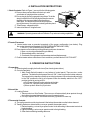
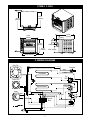
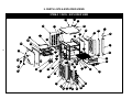
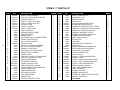
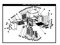
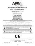
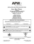
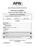
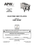
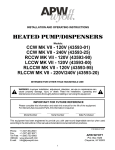
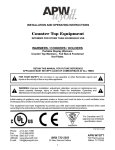
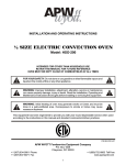
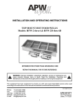
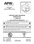
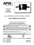
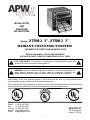
R INSTALLATION AND OPERATING INSTRUCTIONS Models: XTRM-2 3”, XTRM-3 3” RADIANT CONVEYOR TOASTER INTENDED FOR OTHER THAN HOUSEHOLD USE RETAIN THIS MANUAL FOR FUTURE REFERENCE UNIT MUST BE KEPT CLEAR OF COMBUSTIBLES AT ALL TIMES ! FOR YOUR SAFETY: Do not store or use gasoline or other flammable vapors and liquids in the vicinity of this or any other appliance. ! ! WARNING: Improper installation, adjustment, alteration, service or maintenance can cause property damage, injury or death. Read the Installation, Operating and Maintenance Instructions thoroughly before installing or servicing this equipment. ! Initial heating of unit may generate smoke or fumes and must be done in a well ventilated area. Overexposure to smoke or fumes may cause nausea or dizziness. This equipment has been engineered to provide you with year-round dependable service when used according to the instructions in this manual and standard commercial kitchen practices. Phone: Fax: Toll Free: Website: E-mail: P/N 93030077 +1 (214) 421-7366 +1 (214) 565-0976 +1 (800) 527-2100 www.apwwyott.com [email protected] 9/06 APW WYOTT 729 Third Avenue Dallas, TX 75226 1 IMPORTANT FOR FUTURE REFERENCE Please complete this information and retain this manual for the life of the equipment. For Warranty Service and/or Parts, this information is required. Model Number Serial Number Date Purchased Notes: 1. SAFETY PRECAUTIONS Before installing and operating this equipment be sure everyone involved in its operation are fully trained and are aware of all precautions. Accidents and problems can result by a failure to follow fundamental rules and precautions. The following words and symbols, found in this manual, alert you to hazards to the operator, service personnel or the equipment. The words are defined as follows: ! DANGER: This symbol warns of imminent hazard which will result in serious injury or death. ! ! WARNING: This symbol refers to a potential hazard or unsafe practice, which could result in serious injury or death. ! ! CAUTION: This symbol refers to a potential hazard or unsafe practice, which may result in minor or moderate injury or product or property damage. ! ! NOTICE: This symbol refers to information that needs special attention or must be fully understood even though not dangerous. ! APW Wyott takes pride in the design and quality of our products. When used as intended and with proper care and maintenance, you will experience years of reliable operation from this equipment. To ensure best results, it is important that you read and follow the instructions in this manual carefully. Installation and start-up should be performed by a qualified installer who thoroughly read, understands and follows these instruction. If you have questions concerning the installation, operation, maintenance or service of this product, contact APW Wyott Foodservice Equipment Company’s “ Technical Service Department”. 2 TABLE OF CONTENTS SECTION ITEM PAGE 1 Safety Precautions 2 2 Important Safety Instructions 3 3 General Information 4 4 Installation Instructions 5 5 Operation Instructions 5 6 Cleaning Instructions 6 7 Specifications 6 8 Wiring Diagram 7 9 Parts Lists with Exploded Views XTRM-2 3” XTRM-3 3” 8 8 10 10 Warranty 12 2. IMPORTANT SAFETY INSTRUCTIONS ! IMPORTANT: Read the following important safety instructions to avoid personal injury or death, and to avoid damage to the equipment or property. ! ! WARNING: APW Wyott toasters are designed, built, and sold for commercial use. If positioned where the general public can usethem, make sure that all cautions, warnings, and operating instructions are clearly posted near each unit to insureproper operation, reduce the chance of personal injury and/or equipment damage. ! ! WARNING: Plug unit into a properly grounded electrical outlet of the correct voltage, size and plug configuration. If the plug and receptacle do not match, contact a qualified electrician to determine the proper voltage and size and install the proper electrical outlet. ! WARNING: In Europe, appliance must be connected by an earthing cable to all other units in the complete installation and thence to an independent earth connection in compliance with EN 60335-1 and/or local codes ! ! WARNING: Unit is not waterproof. Do not submerge in water. Do not operate if it has been submerged in water. Do not clean the unit with a water jet. ! ! WARNING: To avoid any injury, turn the power switch off at the fuse disconnect switch/circuit breaker or unplug the unit from the power source and allow to cool completely before performing any maintenance or cleaning. ! ! WARNING: To avoid electrical shock, always unplug the unit before performing cleaning or maintenance. ! ! WARNING: An earthing cable must connect the appliance to all other units in the complete installation and from there to an independent earth connection. ! ! WARNING: For safe and proper operation, the unit must be located a reasonable distance from combustible walls and materials. If safe distances are not maintained, discoloration or combustion could occur. ! ! WARNING: To avoid electrical shock or personal injury, do not steam clean or use excessive water on the unit. ! ! WARNING: If service is required on this unit, contact your authorized APW Wyott Service Agent, or contact the APW Wyott Service Department directly at (214) 421-7366 or (800) 527-2100; fax (214) 565-0976. ! ! 3 ! WARNING: This product has no “user” serviceable parts. To avoid damage to the unit or injury to personnel, use only Authorized APW Wyott Service Agents and genuine APW Wyott Parts when service is required.. ! ! WARNING: Genuine APW Wyott Replacement Parts are specified to operate safely in the environments in which they are used. Some aftermarket or generic replacement parts do not have the characteristics that will allow them to operate safely in APW Wyott equipment. It is essential to use APW Wyott Replacement Parts when repairing APW Wyott equipment. Failure to use APW Wyott Replacement Parts may subject operators of the equipment to hazardous electrical voltage, resulting in electrical shock or burn. ! ! CAUTION: Some exterior surfaces on the unit will get hot. Use caution when touching these areas to avoid injury. ! ! CAUTION: Locate the unit at the proper counter height, in an area that is convenient for use. The location should be level to prevent the unit or it’s contents from accidentally falling, and strong enough to support the weight of the unit and food. ! ! CAUTION: Use only non-abrasive cleaners. Abrasive cleaners could scratch the finish of your unit, marring it’s appearance and making it susceptible to dirt accumulation. ! ! WARNING: Failure to provide clearances will cause unit failure and invalidate warranty claims (see installation instructions). ! ! NOTICE: Do not use toppings (butter, etc.) on product as product is inverted during normal operation. ! ! NOTICE: Operating toaster without legs invalidates any warranty claims. ! ! NOTICE: Neglecting to keep fan opening clean could result in toaster failure. ! 3. GENERAL INFORMATION XTRM-2 3”: 1. Overall Dimensions w/Wire Feeder - 16.067”H (408cm) x 16.254”W (41.13cm) x 20.511”D (521cm) 2. Product Opening - 3.0”H (7.62cm) x 10.50”W (26.67cm) 3. Electrical Requirements (Single phase): A. 208 Volt, 2840 Watt, 13.7 Amp. B. 230/240 Volt, 2840 Watt, 11.9 Amp. C. Cordset configuration 1. Each toaster equipped with three wire grounded cordset and standard 3 prong plug. 4. Net/Shipping Weight – 51lb.(23.15kg) / 46lb.(20.865kg) XTRM-3 3”: 1. Overall Dimensions w/Wire Feeder - 16.067”H (408cm) x 19.254”W (489cm) x 20.511”D (521cm) 2. Product Opening - 3.0”H (7.62cm) x 13.50”W (34.29cm) 3. Electrical Requirements (Single phase): A. 208 Volt, 3340 Watt, 16.1 Amp. B. 230/240 Volt, 3340 Watt, 14.0 Amp. C. Cordset configuration 1. Each toaster equipped with three wire grounded cordset and standard 3 prong plug. 4. Net/Shipping Weight – 50 lb.(22.8kg) / 47 lb.(21.319kg) 4 4. INSTALLATION INSTRUCTIONS I. Check Contents: Refer to Figure 1, account for the following parts: A. Remove foam pad and slide reflector tray in with wire feeder in upright position as shown. B. Ensure tray is properly engaged in tray slides. To do this simply hold the front of the tray higher than the rear as the back of the tray must slide under the slide on either side, You will know if done correctly because tray will be secure. No rocking or teetering will take place. C. Toast Drawer - shipped in place D. Instruction Manual - shipped loose ! Figure 1 C WARNING: Operating toaster without Reflector Tray reduces toasting capabilities. A B ! 2. Toaster Placement: A. Locate toaster near a grounded receptacle of the proper configuration (see below). Plug the cordset directly into receptacle (DO NOT USE AN EXTENSION CORD). 1. In the U.S.: 208, 230/240V uses NEMA 6-20R. B. Place toaster on flat surface providing following minimum clearances: 1. Base = one inch (provided with legs installed). 2. Side and back walls = two inches 3. Overhead = Enough space to allow adequate heat displacement. C. Position toaster where customers will not contact any surface labeled “CAUTION HOT”. 5. OPERATION INSTRUCTIONS 1. Preparation A. Clean toaster thoroughly before first use (See cleaning instructions). B. Controls Familiarity 1. Main Power Switch (located on very bottom of control panel): There are two rocker switches. The bottom switch powers the unit “ON”. It also turns on the bottom element. The top switch is a standby switch that runs the top element. When the standby switch is in the “ON” position the unit is at full power. When the standby switch is in the “OFF” position the unit is running at 50%. a) Full Power: Flip both rocker switches to the right. b) Power Off: Flip both rocker switches to the left. c) Warm-up time: Allow five (5) minutes. 2. Normal Use A. Loading Product 1. Place product on Wire Feeder. The conveyor will automatically draw product through the toaster at a speed determined by conveyor speed control. 2. Conveyor Speed Control: Set knob to the three (3) position for warm-up. 3. Thermostat Controls: A. The top thermostat runs the top element & the bottom thermostat runs the bottom element. B. Toasting Darkness: determined by conveyor speed & thermostat control. 1. Darkest toasting - set conveyor speed control to far left setting & thermostat controls to highest setting. 2. Lightest toasting - set conveyor speed control to far right setting. 3. Other factors affecting toasting darkness. 5 a) Product moistness - moister product requires slower speeds b) Sugar content in product - product with more sugar requires slower speeds c) Product Temperature - cooler product requires slower speeds 4. For best results, use day old bread stored room temperature. 6. CLEANING INSTRUCTIONS 1. Daily Cleaning A. With toaster off and cool, turn toaster on and set conveyor speed to four. B. Using a plastic abrasive pad, wipe the conveyor belt in a back and forth motion (side-to side) motion to remove baked-on product. Wipe the conveyor belt in the same manner with a hot, damp cloth. C. Turn off toaster. D. Slide the reflector/crumb tray out of toaster by pulling forward. Dispose of crumbs and wash tray in hot, soapy water. Dry tray and place back in toaster. E. Remove toast drawer from toaster by sliding out and lifting up. Dispose of crumbs and wash drawer in hot, soapy water. Wipe crumbs from inside the toaster with a hot, damp cloth. Dry drawer and place back in toaster. F. Wipe the exterior surfaces of the toaster with a hot, damp cloth. 7. SPECIFICATIONS XTRM-2 3 INCH 19.296 (490mm) 19.408 ISO ME TR IC VIE W 16.254 (413mm) 2.633 16.254 50° 50° 2.521 (64mm) 20.323 (516mm) 20.511 5.593 (142mm) 5.59 3 15.067 (383mm) 2.820 (72mm) 2.820 15.067 16.067 (408mm) 6.654 (169mm) 6.654 13.323 (338mm) 13.323 208V 2850W 6 XTRM-3 3 INCH 16.775 (426mm) 19.293 (490mm) ISO ME TR IC VIE W 19.254 (489mm) 20.655 (525mm) 2.518 (64mm) 50°5.593 (142mm) 15.067 (383mm) 2.820 (72mm) 16.067 (408mm) 6.654 (169mm) 16.323 (415mm) 8. WIRING DIAGRAM Rear Fan Rheostat BLACK BLUE BLACK 8 Top Element BLUE 8 8 Top EGO12 EGO L2Top 12 Control Fan 12 10 8 H2 L1 P2 Pilot P1 10 H1 16 4 Bottom Element Bottom EGO 4Top EGO L2 H2 14 H1 14 P2 Pilot 14 Motor 16 BLACK 16 1 7 L1 11 5 7 L2 L1 G L2 7 6 15 7 5 L2 1 3 Bottom Switch L2 7 L1 2 10 3 3 6 5 3 15 10 1 L1 BLUE Existing Wire 3 Top Switch L2 2 9 9 L1 4 6 Terminal Block 11 11 1 2 2 6 L1 P1 5 5 4 11 9 13 13 9. PARTS LISTS & EXPLODED VIEWS XTRM-2 3 INCH - EXPLODED VIEW 7 61 61 8 63 41 1 1 60 43 44 14 14 5 40 39 6 64 3 13 13 8 22 12 12 42 42 16 16 30 30 21 21 11 11 34 34 18 20 20 18 38 33 54 54 53 53 45 55 59 62 50 50 15 15 57 57 51 51 17 17 28 28 56 36 58 10 10 32 9 31 31 47 49 49 35 44 22 27 26 25 25 23 23 46 46 24 24 29 29 XTRM-2 3” PARTS LIST 9 ITEM P/N 1 2 3 4 5 6 7 8 9 10 11 12 13 14 15 16 17 93030040 93030158 93030159 93030116 93030115 93000225 93030181 93030199 38130 38125 38122 83248 83956 83868 83267 93000226 85149 85144 89184 85284 89076 89030 83261 93230061 70444800 93200066 69104-EGO 69103-EGO 83333 93000186 88705 82920 93100065 93100197 93000233 18* 19* 20 21 22 23 24 25 26 27 28 29 30 31 32 33 DESCRIPTION XTRM-2 3", RIVIET ASSEMBLY XTRM-2 3"-CONTROL PANEL EXTRUSION EXTRUSION, XTRM 2 3" XTRM-2 3", PANEL, LEFT OUTER XTRM-2 3", PANEL, RIGHT SIDE END CAP, F/L & B/R COVER, TOP, XTRM 2 XTRM-2 3", BACK COVER ASSY, CLIP BEARING BEARING FLANGED POLYMER W'ASSY IDLER SHAFT BEARING, SHAFT DRIVE SHAFT ASSY AT-10 SEGMENTED BELT SPACER, CONVEYOR SHAFT LEG 1" PLASTIC W/CHROME END CAP, B/L & F/R MOTOR, AT'S 208/240V 60HZ VARIABLE MOTOR, AT'S 230V 60HZ VARIABLE BUSHING, .875 HEYCO 2126 FAN, COOLING 4.5" 105CFM 208/230V WASHER, LOCK 1/4 INTERNAL SCREW, 10-32X3/4 SPROCKET, 12 TOOTH 1/4 PITCH 3/8 BORE ASSY, PLATE, CONTROLS 3" XTRM SWITCH, ROCKER ON-OFF PLATE, SPACE, CONTROLS INFINITE SWITCH-EGO (208V) INFINITE SWITCH-EGO (230/240V) RHEOSTAT 208/240 V. PIGGY-BACK TERM XTRM-2, ELEMENT RACK KNOB 039-266 8A BLACK BELT, WIRE 27x.05 3 SEG. ASSY, XTRM 2 FEEDER DRAWER TOAST SPROCKET, 32 TOOTH 1/4 PITCH QUAN ITEM 1 1 1 1 1 2 1 1 2 2 1 2 1 2 4 2 1 1 1 1 4 4 1 1 2 1 2 2 1 2 2 1 1 1 1 34 35 36 37* 38 39 40 41 42 43 44 45 46 47 48* 49 50 51 52* 53 54 55 56 57 58 59 60 61 62 63 64 65* 66* P/N 82902 75617 83821 89061 93000194 93000229 89073 88889 81600087 89111 83277 89145 93230064 89054 85287 88923 89063 94000114 93200084 85281 93000196 85282 93030227 88940 93030230 93030231 93030232 89039 93200303 58081 54093 54094 69154 89182 DESCRIPTION CHAIN, 1/4" DRIVE 67 PITCH KNOB W/NO'S. 0 TO 9 BRACKET, BEARING NUT, HEX 10-24 XTRM 2&3, SMALL ELEMENT COVER HEX MACHINE SCREW, #6-32 X 3/4 SCREW, #8 X 1/2 HEX TAPIT SHT MTL TYPE AB SCREW #8 X 1/2 AB SMS PHL TRUSS LGM NI PLT SCREW, 8-32 x 3/8, PHILLIPS, PAN HEAD BUSHING, STRAIN RELIEF SR-7W-2 CORDSET, ASSY 208/240V (CORD 85640) TERMINAL BLOCK 300V-30AMPS LABEL, XTRM CONTROL 3" NUT, KEPS 6-32 FAN GUARD SCREW, 8-32x1-3/4 SLT PAN MS SS NUT, HEX 8-32 SCREW, COUNTERSINK, 6-32X5/16,Z,BLK XTRM-3, INSULATION CENTER PANEL FAN,COOLING,3" DIA, 208/230V XTRM-2 & 3 AIR DEFLECTOR Guard, 3.15 Sq. Fan XTRM-2 3", CONTROL BOX INSULATION WASHER, 1-1/2 RD XTRM-2 3", RIGHT EXTRUSION INSULATION XTRM-2 3", LEFT EXTRUSION INSULATION XTRM-2 3", RIGHT SIDE INSULATION SCREW, 8-32X5/16 PH PAN SS LABEL, SPEED GUIDCAUTION HOT! LABEL, CAUTION HOT! ELEMENT, 208V-1400W ELEMENT, 230/240V-1400W THERMOSTAT, THERM-O-DISC W/MOUNT CLIP BUSHING, .5 HEYCO 2058 *NOT SHOWN QUAN 1 1 2 10 4 8 10 12 2 1 1 1 1 2 1 8 8 12 1 1 1 1 2 9 2 2 2 4 1 1 2 2 1 1 XTRM-3 3 INCH - EXPLODED VIEW 16 64 19 20 17 1 11 35 13 36 59 7 61 40 58 39 5 49 6 42 37 62 27 43 54 3 56 15 10 21 9 33 29 60 32 55 31 52 51 44 48 57 63 46 53 34 14 4 28 25 2 26 24 22 45 23 30 30 8 XTRM-3 3” PARTS LIST 11 ITEM P/N 1 2 3 4 5 6 7 8 9 10* 11 12* 13 14 15 16 93230040 93030158 93030159 93030116 93030115 93000225 93230047 38130 38125 93200070 83248 83976 83868 83267 93000226 85149 85144 89184 85284 89076 89030 83261 93230061 70444800 93200066 69104-EGO 69103-EGO 83333 93200036 88705 83880 93200052 93200048 93000233 82902 75617 17 18* 19 20 21 22 23 24 25 26 27 28 29 30 31 32 33 34 DESCRIPTION XTRM 3 3", RIVIET ASSEMBLY XTRM-2 3"-CONTROL PANEL EXTRUSION EXTRUSION, XTRM 2 3" XTRM-2 3", PANEL, LEFT OUTER XTRM-2 3", PANEL, RIGHT SIDE END CAP, F/L & B/R COVER, TOP, XTRM 3 ASSY, CLIP BEARING BEARING FLANGED POLYMER SHAFT, IDLER XTRM BEARING, SHAFT ASSEMBLY, DRIVE SHAFT SPACER, CONVEYOR SHAFT LEG 1" PLASTIC W/CHROME END CAP, B/L & F/R MOTOR, AT'S 208/240V 60HZ VARIABLE MOTOR, AT'S 230V 60HZ VARIABLE BUSHING, .875 HEYCO 2126 FAN, COOLING 4.5" 105CFM 208/230V WASHER, LOCK 1/4 INTERNAL SCREW, 10-32X3/4 SPROCKET, 12 TOOTH 1/4 PITCH 3/8 BORE ASSY, PLATE, CONTROLS 3" XTRM SWITCH, ROCKER ON-OFF PLATE, SPACE, CONTROLS INFINITE SWITCH-EGO (208V) INFINITE SWITCH-EGO (230/240V) RHEOSTAT 208/240 V. PIGGY-BACK TERM XTRM 3, ELEMENT RACK KNOB 039-266 8A BLACK CONVEYOR BELT 79 LINKS ASSY, XTRM 3 FEEDER XTRM-3, TOASTER DRAWER SPROCKET, 32 TOOTH 1/4 PITCH CHAIN, 1/4" DRIVE 67 PITCH KNOB W/NO'S. 0 TO 9 QUAN ITEM 1 1 1 1 1 2 1 2 2 1 2 1 2 4 2 1 1 1 1 4 4 1 1 2 1 2 2 1 2 2 1 1 1 1 1 1 35 36 37 38* 39 40 41* 42 43 44 45 46 47* 48 49 50* 51 52 53 54 55 56 57 58 59 60 61 62 63 64 65* 66* 67* P/N 83821 89061 93000194 93000229 89073 88889 81600087 89111 83277 89145 93230064 89054 85287 89063 94000114 93200084 85281 93000196 85282 93030227 88940 93030230 93030231 93030232 89039 93200303 58081 54021 54032 88951 93230199 69154 89056 89182 DESCRIPTION BRACKET, BEARING NUT, HEX 10-24 XTRM 2&3, SMALL ELEMENT COVER HEX MACHINE SCREW, #6-32 X 3/4 SCREW, #8 X 1/2 HEX TAPIT SHT MTL TYPE AB SCREW #8 X 1/2 AB SMS PHL TRUSS LGM NI PLT SCREW, 8-32 x 3/8, PHILLIPS, PAN HEAD BUSHING, STRAIN RELIEF SR-7W-2 CORDSET, ASSY 208/240V (CORD 85640) TERMINAL BLOCK 300V-30AMPS LABEL, XTRM CONTROL 3" NUT, KEPS 6-32 FAN GUARD NUT, HEX 8-32 SCREW, COUNTERSINK, 6-32X5/16,Z,BLK XTRM-3, INSULATION CENTER PANEL FAN,COOLING,3" DIA, 208/230V XTRM-2 & 3 AIR DEFLECTOR Guard, 3.15 Sq. Fan XTRM-2 3", CONTROL BOX INSULATION WASHER, 1-1/2 RD XTRM-2 3", RIGHT EXTRUSION INSULATION XTRM-2 3", LEFT EXTRUSION INSULATION XTRM-2 3", RIGHT SIDE INSULATION SCREW, 8-32X5/16 PH PAN SS LABEL, SPEED GUIDCAUTION HOT! LABEL, CAUTION HOT! ELEMENT, 208V - 1650W ELEMENT, 230/240V - 1650W SCREW, 8-32x2" PHILLIPS PAN MS SS XTRM 3 3", BACK COVER THERMOSTAT, THERM-O-DISC W/MOUNT CLIP WASHER #8 INTERNAL LOCK, SS BUSHING, .5 HEYCO 2058 *NOT SHOWN QUAN 2 10 4 8 10 12 2 1 1 1 1 2 1 9 12 1 1 1 1 2 9 2 2 2 4 1 1 2 2 8 1 1 1 1 10. APW WYOTT EQUIPMENT LIMITED WARRANTY APW Wyott Foodservice Equipment Company warrants it's equipment against defects in materials and workmanship, subject to the following conditions: This warranty applies to the original owner only and is not assignable. Should any product fail to function in its intended manner under normal use within the limits defined in this warranty, at the option of APW Wyott such product will be repaired or replaced by APW Wyott or its Authorized Service Agency. APW Wyott will only be responsible for charges incurred or service performed by its Authorized Service Agencies. The use of other than APW Wyott Authorized Service Agencies will void this warranty and APW Wyott will not be responsible for such work or any charges associated with same. The closest APW Wyott Authorized Service Agent must be used. This warranty covers products shipped into the 48 contiguous United States, Hawaii, metropolitan areas of Alaska and Canada. There will be no labor coverage for equipment located on any island not connected by roadway to the mainland. Warranty coverage on products used outside the 48 contiguous United States, Hawaii, and metropolitan areas of Alaska and Canada may vary. Contact the international APW Wyott distributor, dealer, or service agency for details. Time Period One year for parts and one year for labor, effective from the date of purchase by the original owner. The Authorized Service Agency may, at their option, require proof of purchase. Parts replaced under this warranty are warranted for the un-expired portion of the original product warranty only. Exceptions *Gas/Electric Cookline: Models GCB, GCRB, GF, GGM, GGT, CHP-H, EF, EG, EHP. Three (3) Year Warranty on all component parts, except switches and thermostats. (2 additional years on parts only. No labor on second or third year.) *Broiler Briquettes, Rock Grates, Cooking Grates, Burner Shields, Fireboxes: *Heat Strips: *Glass Windows, Doors, Seals, Rubber Seals, Light Bulbs: Models FD, FDL, FDD, FDDL. 90 Day Material Only. No Labor. Two (2) Year Warranty on element only. 90 Day Material Only. No labor second year. No Labor. In all cases, parts covered by extended warranty will be shipped FOB the factory after the first year. Portable Carry In Products Equipment weighing over 70 pounds or permanently installed will be serviced on-site as per the terms of this warranty. Equipment weighing 70 pounds or under, and which is not permanently installed, i.e. with cord and plug, is considered portable and is subject to the following warranty handling limitations. If portable equipment fails to operate in its intended manner on the first day of connection, or use, at APW Wyott's option or its Authorized Service Agency, it will be serviced on site or replaced. From day two through the conclusion of this warranty period, portable units must be taken to or sent prepaid to the APW Wyott Authorized Service Agency for in-warranty repairs. No mileage or travel charges are allowed on portable units after the first day of use. If the customer wants on-site service, they may receive same by paying the travel and mileage charges. Exceptions to this rule: (1) countertop warmers and cookers, which are covered under the Enhanced Warranty Program, and (2) toasters or rollergrills which have in store service. Exclusions The following conditions are not covered by warranty: *Equipment failure relating to improper installation, improper utility connection or supply and problems due to ventilation. *Equipment that has not been properly maintained, calibration of controls, adjustments, damage from improper cleaning and water damage to controls. *Equipment that has not been used in an appropriate manner, or has been subject to misuse or misapplication, neglect, abuse, accident, alteration, negligence, damage during transit, delivery or installation, fire, flood, riot or act of god. *Equipment that has the model number or serial number removed or altered. If the equipment has been changed, altered, modified or repaired by other than an Authorized Service Agency during or after the warranty period, then the manufacturer shall not be liable for any damages to any person or to any property, which may result from the use of the equipment thereafter. This warranty does not cover services performed at overtime or premium labor rates. Should service be required at times which normally involve overtime or premium labor rates, the owner shall be charged for the difference between normal service rates and such premium rates. APW Wyott does not assume any liability for extended delays in replacing or repairing any items beyond its control. In all cases, the use of other than APW Wyott Authorized OEM Replacement Parts will void this warranty. This equipment is intended for commercial use only. Warranty is void if equipment is installed in other than commercial application. Water Quality Requirements Water supply intended for a unit that has in excess of 3.0 grains of hardness per gallon (GPG) must be treated or softened before being used. Water containing over 3.0 GPG will decrease the efficiency and reduce the operation life of the unit. Note: Product failure caused by liming or sediment buildup is not covered under warranty. THE FOREGOING WARRANTY IS IN LIEU OF ANY AND ALL OTHER WARRANTIES EXPRESSED OR IMPLIED INCLUDING ANY IMPLIED WARRANTY OF MERCHANTABILITY OR FITNESS FOR PARTICULAR PURPOSES AND CONSTITUTES THE ENTIRE LIABILITY OF APW WYOTT. IN NO EVENT DOES THE LIMITED WARRANTY EXTEND BEYOND THE TERMS STATED HEREIN. 9/05 12