1
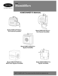
HEATING
& COOLING
HOMEOWNER'S
Model HUMCCLFP1025-A-Fan-Powered
Humidifier
MANUAL
Model HUMCCSFP1016-A-Fan-Powered
Humidifier
Model HUMCCLBP2018-A-Bypass
Model HUMCCWTR2019-A-Water-Saver
Bypass
Humidifier
Humidifier
Model HUMCCSBP2017-A-Bypass Humidifier
REFRESHING MOISTURE...
AS NATURE INTENDED
Congratulations on your excellent choice and sound investlnent
in this addition m your holne COlnfort system.
the large evaporator pad. Hot, dry air [}oln the furnace passes
through the pad and absorbs the water. Then, this lnoisture-laden
air is distributed throughout the house via the ductwork. See Fig.
1, 2, and 3.
Your hulnidifier represents both the latest in engineering developlnent and the cuhnination of lnany years of experience t}Oln
one of the lnost reputable lnanufacturers of comfort systems.
Your new unit is alnong the most energy-efcient
and reliable
holne hulnidifiers available today. To assure its dependability,
spend a few lninutes now with this booklet. Learn about the operation of your hulnidifier and the small alnount oflnaintenance
it takes to keep it operating at peak efficiency.
With lninilnal care, your hulnidifier will provide you and your
_amily with lnoist, spring-fresh air
froln season to season and
year to year.
YOUR
Fig. 1
Fig. 2
HOME HUMIDIFIER
YOUR HOME CAN BE DRIERTHAN
DEATH VALLEY
During the heating season, your holne can becolne uncolnfortably dry. This is because cold winter air holds very little lnoisrare. When outdoor air is warmed to average rooln telnperamre,
its relative hulnidity £hlls to even lower levels. Refer to Table 1
for a comparison of the levels of relative humidity for a few sample enviromnents.
Table 1 -- Relative Humidity
HEATED
TYPICAL
INSTALLATIONS
Comparison
HOME
Fig. 3
RECOMMENDED
RELATIVE
HUMIDITY
SAHARA
DEATH
DESERT
VALLEY
HEATED
HOME
AVERAGE
35%
25%
23%
5-15%
Parched air can cause the wood used in the construction of your
house and furnishings to dry, crack, aM split. Draperies and upholstery may age prelnaturely. Amaoying static electric shock
and cling are lnore prevalent. Your tlaoat, nasal passages, sinuses, and skin are more susceptible to irritating dryness. You
may even have to set the therlnostat higher than otherwise necessary
just to feel warm.
MOISTURE MAKES A REFRESHING DIFFERENCE
Proper hulnidity comrol can alleviate problelns caused by excessive dryness. Furnishings and fabrics take on a more lustrous
appearance. Houseplants tl_ive. Static electricity is significantly
reduced in a properly hulnidified home. Your £hmily will breathe
lnore easily and ilnd relief from the cool, drafty feeling coinlnonly experienced in overly dry holnes. The additional lnoisture
supplied by your humidifier may enable you to reduce the temperature setting on your therlnostat
without any loss of indoor
COlnfort.
HOWYOUR HUMIDIFIERWORKS
Your hulnidifier adds water lnolecules to the air inside your
holne. Although the rate of humidification is variable, it may
exceed one-half gallon of water per hour. That's a healthy drink
for a dry household. The typical process of lmlnidification begins when water flows through the humidifier vah,e and soaks
OPERATING
YOUR HUMIDIFIER
Your new hulnidifier is designed to operate as part of your home
heating system. It will perforln at lnaximuln efciency if these
recolranendations are followed:
• The hulnidifier is comrolled by a hulnidistat. Adjust the
hulnidistat setting according to the outside telnperature. Refer
to Table 2 as a general guide. If after several days, the air in
your home seems too moist, lower the humidistat setting. Condensation on single-pane windows indicates excessive moisture. If the air is too dry, increase the setting. Dry throat and
nasal passages indicate dry air.
• All models come with a humidistat. Continuous blower operation provides for constant hulnidification. It may also contribute to greater personal COlnfort because continuous blower
operation minimizes telnperature differences throughout the
home. Furtherlnore, a system equipped with an electronic air
cleaner offers the added benefit of full-tilne air filtration.
Table 2--HumidistatSettings
OUTSIDE
TEMPERATURE
(°F)
-20
RECOMMENDED
HUMIDISTAT SETTING
(% RELATIVE HUMIDITY)
15
-10
-0
10
20
20 (LOW)
25
30
35
30
40 (NED)
• Supply- and return-air grilles should not be blocked by items
such as drapes, flmfiture, and toys. Restricted airflow reduces
the efficiency of the humidifier, as well as that of the whole comfort system.
• The humidifier unit lnUSt be properly lnaintained on a regular
basis.
STARTUP PROCEDURES
1. Open the saddle valve on the water supply line. (See Fig. 4.)
Set humidistat to the desired relative humidity. (See Fig. 5
and Table 2.)
2. Turn the fimmce on and adjust the therlnostat to a high temperature setting. Be sure that the fitmace blower is operating.
3. Check to see if water is flowing into the humidifier.
Fig. 7 -- Model HUMCCLP1025-A--
Fig. 4 -- Saddle Valve
Fig. 5
CABINET_
NLET
_
_SOLENO_DVALVE
D_STR_BUTORPAN
• On a Model HUMCCLBP or Model HUMCCLFP humidifier, loosen the thulnbscrew that holds the distributor cover to the
mp of the cabinet. Lift up the distributor cover slightly to lnake
certain that water is flowing from the solenoid valve into the
distributor pan. Do not lift the cover offthe cabinet more than
1 in. when water is flowing. (See Fig. 6 or 7 according to the
lnodel you own.)
DRAIN J
Fig. 8 -- Model HUMCCSBP2017-A-DISTRIBUTOR PAN J
BOTTOM ACCESS -Z
PANEL
Fig. 6 -- Model HUMCCLBP2018-A-• On a Model HUMCCSBP humidifier, gemly pull the latch
that secures the access door. Relnove the door. Check to see if
water is flowing froln the solenoid valve into the evaporator pad.
(See Fig. 8.)
• On a Model HUMCCSFP hulnidifier, open the side door or
the front cover. If the front cover is opened, hold the pad assembly in place. Check to see if water is flowing from the solenoid
valve imo the distributor pan. (See Fig. 9.)
Fig. 9 -- Model HUMCCSFP1016-A--
• On a Model HUMCCWTR unit, look through the window on
front of the unit to see that the evaporator pad is rotating and
water is flowing. (See Fig. 10.)
4. Turn off the furnace. When the blower stops, look into the
humidifier to make sure the water is not flowing into the
unit.
The Model HUMCCWTR is controlled by a float valve. Turning
off the fimmce will not affect the water flow until float level is
achieved. (See Fig. 11.)
5. Replace the cover assembly and *hsten securely.
6. Now, mrn the furnace on and set the thermostat for desired
rooln telnperature.
SHUTDOWN PROCEDURES
CLEANING PROCEDURES
To shut down your humidifier, close the saddle vane on the water line. Then turn off the humidistat. When set to the OFF position, the humidistat shuts offthe electrical power m the solenoid
valve on the humidifier.
Models HUMCCLBP, HUMCCSBP, HUMCCLFP, and
HUMCCSFP
1. Turn off all electrical power to the humidifier and fimmce
or fan coil.
NOTE: If your holne comfort system includes cooling, be sure
the water supply to your humidifier is turn ed off during the cooling season. Close the damper located in the bypass duct if one
is installed. If your humidifier is a Model HUMCCWTR, drain
and clean the water pan as described in cleaning procedures.
PERFORMING
ROUTINE
2. Turn offthe humidifier's water supply. (See Fig. 4.)
3. Disassemble the humidifier.
• To disasselnble a Model HUMCCSBP humidifier, gently pull
the latch that secures the access panel. Relnove the door and
slide the evaporator pad assembly out of the unit. (See Fig. 8.)
MAINTENANCE
• To disassemble either a Model HUMCCLBP or Model
HUMCCLFP humidifier, first relnove the water supply connection to the solenoid valve. Next, relnove the screw that
holds the distributor cover to the cabinet, and lift offthe cover.
Discom_ect the drain line from the sump and loosen the
thumbscrew(s) holding the sump to the cabinet. Relnove the
sump. Relnove evaporator pad assembly. (See Fig. 6 or 7,
according to the lnodel you own.)
With the proper lnaintenance and care, your humidifier will operate econolnically and dependably. Maintenance can be accomplished easily by referring to the following directions. However,
before perforlning any lnaintenance, consider these ilnportant
safety precautions:
• DISCONNECT ALL ELECTRICAL
POWER TO THE
HUMIDIFIER AND FURNACE BEFORE PERFORMING
ANY SERVICE OR MAINTENANCE
TO AVOID PERSONAL INJURY.
• To disassemble a Model HUMCCSFR the pad assembly can
be relnoved froln the side access door or the front cover. When
relnoving the side door, lift the pad asselnbly up by holding the
tabs and slide the asselnbly out. When relnoving the front cover
on Model HUMCCSFR discomaect the quick comaects m the
solenoid valve, unscrew the 4 screws to the front cover, snap
loose the mp and bottom catches, and lay the front cover aside.
Once the front cover is off; lift the pad assembly up aM twist it
out. The pad assembly consists of 4 parts; the distributor pan,
fralne, sump, and the evaporator pad. Pull the distributor pan
apart from the fralne and the evaporator pad can be relnoved. Do
not force the evaporator pad in or out without relnoving the distributor pan as this will distort the pad.
4. Clean the humidifier's external COlnponents.
• If your humidifier is a Model HUMCCSBP humidifier, wash
the access door and outlet drain portion of the cabinet. Make
sure the drain is open.
- CABINET
• If your humidifier is a Model HUMCCLBP or HUMCCLFR
wash the distributor cover, sump cover, and cabinet. Be sure the
inlet ports are open and clean. Then, clean the sump with a solution of detergent and water.
PAN
Fig. 10 -- Model HUMCCWTR2019-A--
5. Clean the internal colnponents of your humidifier. Wash the
distributor pan with a mild detergent and warm water. Be
sure holes and slots in the pan are clean and unobsmlcted.
Wash the evaporator pad assembly in a detergent solution.
If there are scale deposits on the pad, soak it in ordinary
household vinegar. If the pad is covered by a heavy deposit
of scale, or if the local water supply has high sullhte or calcium content, replace the pad with a new one. Contact your
dealer for replacement part.
6. Reassemble your humidifier.
7. Turn on the electrical power and water supplies. Refer to
the starmp procedures.
NOTE: THERE MAY BE MORE THAN 1 ELECTRICAL
DISCONNECT SWITCH.
• ALTHOUGH SPECIAL CARE HAS BEEN TAKEN TO
MINIMIZE SHARP EDGES IN THE CONSTRUCTION OF
YOUR HUMIDIFIER, BE EXTREMELY CAREFUL WHEN
HANDLING PARTS OR REACHING INTO THE WNIT TO
AVOID PERSONAL INJURY.
Your hulnidifier has been designed for easy disassembly to simplii_ cleaning and selwicing. Your unit lnUSt be kept clean m
lnaintain its efficiency.
Model HUMCCWTR
1. Turn off all electrical power to the humidifier and furnace
or £hn coil.
Regular inspection allows you to deterlnine the cleaning schedule best suited to your humidifier's operating conditions. The
frequency for required lnaintenance will depend most upon the
available water supply. In areas where hard water and high lnineral content are prevalent, lnore frequent cleaning and servicing
may be required.
2. Turn off the humidifier's water supply. (See Fig. 4.)
3. Drain water from the unit. Place a pail underneath the drain
plug located on the bottom of the humidifier cabinet. Lift
the tab on the drain plug and relnove the plug. Allow all
water m drain fiOln the unit. (See Fig. 12.)
At minimum, the humidifier will need to be cleaned at the beginning of every heating season.
4
4.Relnove
thefrontdoorfrolnthehumidifienRotatethe BEFOREYOU REQUEST A "SERVICE CALL"
latches
one-half
turn,thenpullthedoorforward.
BEFOREYOU CALL FOR SERVICE, CHECK FOR
5.Relnove
andinspect
theevaporator
padassembly.
Liftthe THESE EASILY SOLVED PROBLEMS:
bearing
fromitsretainer.
(SeeFig.10.)Pulltheassembly
awayfromthelnotortodisengage
theassembly
shalifroln • Check the lnain power discomaect
themotorcoupling.
Relnove
assembly
tl_oughtheaccess switch. Verify that the circuit breakers are on and that fuses have not
opening.
blown.
If you lnUSt reset breakers or
Inspecttheevaporator
pad.If thepadis heavilyloaded
with
replace
filses, do so only once. Conscale,
orif thelocalwaterhasahighsulfhte
content,
replace
the
tact your selwicing dealer for assispad.Contact
yourdealer
forreplacelnent
part.
tance if the breakers trip or the filses
NOTE: Forbestperforlnance,
theevaporator
padshouldbe blow
a second time.
replaced
before
eachheating
season.
6.Inspect
thefloatassembly.
Relnove
thefloatarmfromthe • If the hulnidity level is too low, check the hulnidistat setting.
valvebodyby slidingoutthepinandliftingoffthefloat Confirln that the saddle valve is turned on. Check the evaporaarm.(See
Fig.11.)Inspect
therubber
valveseatlocated
in- tor pad, and clean or replace the pad as necessary. Check water
sidethefloatarm.If theseatappears
tobenickedorworn, level in Model HUMCCWTR.
inverttheseatorreplace
it withthespare
valveseatlocated • Check for sufficient airflow. Check the fimmce filter or eleconthefloatarm.Inspectthewateropeningin thevalve mmic air cleaner for excessive accumulations of dirt. Check for
body.If theopening
is clogged,
usea pintorelnove
the
return- or supply-air grilles. Be sure grilles are open
obstruction.
Remove
anyaccumulated
deposits
frolnthe blocked
and unobstructed.
valvebodyandfloatarm.
7.Clean
thewaterpanandunitcabinet.
Tiltthewaterpanand • If water drips froln the humidifier, check the drain hose for
lift it fiOlntheunit.Wash
thepanwithwarm,soapy
water. kinks or obstructions. If your unit is a Model HUMCCWTR,
Flexthepantoloosen
accumulated
scale.
Washtheunitin- dripping may indicate that the float valve requires adjustlnent.
terior,relnovinganyaccumulated
deposits.
Inspectthe If your colnfort system still fhils to operate properly, contact
drainlinetoinsurethatnoblockage
hasoccurred.
Cleanas your selwicing dealer for troubleshooting and repairs. Specify
required.
(SeeFig.12.)
your apparent probleln, and state the lnodel and serial nulnbers
8.Reassemble
yourModelHUMCCWTR
humidifier.
Rein- of your equiplnent. (You should have theln recorded where
sertthewaterpananddrainplug.Ensure
thattheoverflow noted in this booldet.) With this inforlnation, your dealer lnay be
tubeis inserted
intotheholeatthebottomofthecabinet. able to offer helpfid suggestions over the phone, or save valuable
Attachthefloatarmtothevalvebodybyaligning
theholes time through knowledgeable preparation for the selwice call.
onbothpartsandreinserting
thepin.Do notfbrce or bend
thepin. The float arm should have flee up-and-down movelnent. Install the evaporator pad assembly. Ensure that the
square shaft engages the lnotor coupling and that the bearing washer is located inside the bearing retainer. Turn the
water on. Adjust float by rotating until water covers inside
of foaln drum. Attach the access door and turn the latches.
FLOAT ARM
PiN --_
W; LAT
Fig. 11 -- Float Arm Removal
f
Ho_.,,o,F,ER
HOOS,NG
fWATERPAN
H
H
REGULAR DEALER MAINTENANCE
In addition to the routine lnaintenance that you perforln, your
humidifier should be inspected regularly by a properly trained
selwice technician. The inspection (preferably each year, but at
least every other year) should include the following:
• Routine inspection of the hulnidifier. Cleaning, if necessary.
Cleaning or replacelnent of the evaporator pad as required.
• A check of all electrical wiring and comaections.
• A check of water comaections to the unit.
Fig. 12 -- Cleaning Water Pan and Unit Cabinet
9. Turn on electrical power supplies. Refer to starmp procedures listed on page 3.
• Operational
check of the complete colnfort system to determine acttml worldng condition. Necessary repair and/or adjustlnent should be perforlned at this time.
Your selwicing dealer lnay offer an econolnical
service contract
that covers seasonal inspections. Ask for further details.
Record the lnodel and serial nulnbers of your new hulnidifier in
the following spaces. This inforlnation, along with the other
ready-reference facts requested below, may be required if you
should ever need inforlnation or selaqce.
Model No.
Serial No.
Date Installed
Dealer Name
Address
City
State
Zip
Telephone
Carrier
A United Technologies
TO OBTAIN
Company
INFORMATION
ON PARTS: Consult your installing
dealer or the classified
section of your local telephone directory
"Heating
Equipment" or "Air Conditioning
Contractors
& Systems" heading for dealer listing by brand name.
Have available the Model No., Series Letter, & Serial No. of your equipment
to ensure correct replacement
part
Carrier Corporation
under the
• Indianapolis, IN 46231
Manufacturer reserves the right to discontinue, or change at any time, specifications or designs without notice and without incurring obligations.
Copyright
1998 Carrier Corporation
Form: OMHUM-1
Replaces:
OM49-9
Printed in the US.A.
7-98
PC 101
Catatog No. 03HU-MC0